WO2020004629A1 - Dispositif de récupération d'air pollué - Google Patents
Dispositif de récupération d'air pollué Download PDFInfo
- Publication number
- WO2020004629A1 WO2020004629A1 PCT/JP2019/025855 JP2019025855W WO2020004629A1 WO 2020004629 A1 WO2020004629 A1 WO 2020004629A1 JP 2019025855 W JP2019025855 W JP 2019025855W WO 2020004629 A1 WO2020004629 A1 WO 2020004629A1
- Authority
- WO
- WIPO (PCT)
- Prior art keywords
- air
- storage container
- gas
- air storage
- supply pipe
- Prior art date
- Legal status (The legal status is an assumption and is not a legal conclusion. Google has not performed a legal analysis and makes no representation as to the accuracy of the status listed.)
- Ceased
Links
Images






Classifications
-
- B—PERFORMING OPERATIONS; TRANSPORTING
- B01—PHYSICAL OR CHEMICAL PROCESSES OR APPARATUS IN GENERAL
- B01D—SEPARATION
- B01D39/00—Filtering material for liquid or gaseous fluids
- B01D39/14—Other self-supporting filtering material ; Other filtering material
- B01D39/20—Other self-supporting filtering material ; Other filtering material of inorganic material, e.g. asbestos paper, metallic filtering material of non-woven wires
- B01D39/2003—Glass or glassy material
- B01D39/2017—Glass or glassy material the material being filamentary or fibrous
-
- B—PERFORMING OPERATIONS; TRANSPORTING
- B01—PHYSICAL OR CHEMICAL PROCESSES OR APPARATUS IN GENERAL
- B01D—SEPARATION
- B01D53/00—Separation of gases or vapours; Recovering vapours of volatile solvents from gases; Chemical or biological purification of waste gases, e.g. engine exhaust gases, smoke, fumes, flue gases, aerosols
- B01D53/34—Chemical or biological purification of waste gases
- B01D53/346—Controlling the process
-
- B—PERFORMING OPERATIONS; TRANSPORTING
- B01—PHYSICAL OR CHEMICAL PROCESSES OR APPARATUS IN GENERAL
- B01D—SEPARATION
- B01D53/00—Separation of gases or vapours; Recovering vapours of volatile solvents from gases; Chemical or biological purification of waste gases, e.g. engine exhaust gases, smoke, fumes, flue gases, aerosols
- B01D53/34—Chemical or biological purification of waste gases
-
- B—PERFORMING OPERATIONS; TRANSPORTING
- B01—PHYSICAL OR CHEMICAL PROCESSES OR APPARATUS IN GENERAL
- B01D—SEPARATION
- B01D53/00—Separation of gases or vapours; Recovering vapours of volatile solvents from gases; Chemical or biological purification of waste gases, e.g. engine exhaust gases, smoke, fumes, flue gases, aerosols
- B01D53/34—Chemical or biological purification of waste gases
- B01D53/73—After-treatment of removed components
-
- B—PERFORMING OPERATIONS; TRANSPORTING
- B01—PHYSICAL OR CHEMICAL PROCESSES OR APPARATUS IN GENERAL
- B01D—SEPARATION
- B01D53/00—Separation of gases or vapours; Recovering vapours of volatile solvents from gases; Chemical or biological purification of waste gases, e.g. engine exhaust gases, smoke, fumes, flue gases, aerosols
- B01D53/34—Chemical or biological purification of waste gases
- B01D53/74—General processes for purification of waste gases; Apparatus or devices specially adapted therefor
- B01D53/75—Multi-step processes
-
- B—PERFORMING OPERATIONS; TRANSPORTING
- B01—PHYSICAL OR CHEMICAL PROCESSES OR APPARATUS IN GENERAL
- B01D—SEPARATION
- B01D53/00—Separation of gases or vapours; Recovering vapours of volatile solvents from gases; Chemical or biological purification of waste gases, e.g. engine exhaust gases, smoke, fumes, flue gases, aerosols
- B01D53/34—Chemical or biological purification of waste gases
- B01D53/74—General processes for purification of waste gases; Apparatus or devices specially adapted therefor
- B01D53/76—Gas phase processes, e.g. by using aerosols
-
- B—PERFORMING OPERATIONS; TRANSPORTING
- B01—PHYSICAL OR CHEMICAL PROCESSES OR APPARATUS IN GENERAL
- B01D—SEPARATION
- B01D53/00—Separation of gases or vapours; Recovering vapours of volatile solvents from gases; Chemical or biological purification of waste gases, e.g. engine exhaust gases, smoke, fumes, flue gases, aerosols
- B01D53/34—Chemical or biological purification of waste gases
- B01D53/74—General processes for purification of waste gases; Apparatus or devices specially adapted therefor
- B01D53/77—Liquid phase processes
- B01D53/78—Liquid phase processes with gas-liquid contact
-
- B—PERFORMING OPERATIONS; TRANSPORTING
- B01—PHYSICAL OR CHEMICAL PROCESSES OR APPARATUS IN GENERAL
- B01J—CHEMICAL OR PHYSICAL PROCESSES, e.g. CATALYSIS OR COLLOID CHEMISTRY; THEIR RELEVANT APPARATUS
- B01J19/00—Chemical, physical or physico-chemical processes in general; Their relevant apparatus
-
- B—PERFORMING OPERATIONS; TRANSPORTING
- B01—PHYSICAL OR CHEMICAL PROCESSES OR APPARATUS IN GENERAL
- B01D—SEPARATION
- B01D2251/00—Reactants
- B01D2251/95—Specific microorganisms
-
- B—PERFORMING OPERATIONS; TRANSPORTING
- B01—PHYSICAL OR CHEMICAL PROCESSES OR APPARATUS IN GENERAL
- B01D—SEPARATION
- B01D2252/00—Absorbents, i.e. solvents and liquid materials for gas absorption
- B01D2252/10—Inorganic absorbents
- B01D2252/103—Water
- B01D2252/1035—Sea water
-
- B—PERFORMING OPERATIONS; TRANSPORTING
- B01—PHYSICAL OR CHEMICAL PROCESSES OR APPARATUS IN GENERAL
- B01D—SEPARATION
- B01D2257/00—Components to be removed
- B01D2257/30—Sulfur compounds
- B01D2257/302—Sulfur oxides
-
- B—PERFORMING OPERATIONS; TRANSPORTING
- B01—PHYSICAL OR CHEMICAL PROCESSES OR APPARATUS IN GENERAL
- B01D—SEPARATION
- B01D2257/00—Components to be removed
- B01D2257/40—Nitrogen compounds
- B01D2257/404—Nitrogen oxides other than dinitrogen oxide
-
- B—PERFORMING OPERATIONS; TRANSPORTING
- B01—PHYSICAL OR CHEMICAL PROCESSES OR APPARATUS IN GENERAL
- B01D—SEPARATION
- B01D2257/00—Components to be removed
- B01D2257/80—Water
-
- B—PERFORMING OPERATIONS; TRANSPORTING
- B01—PHYSICAL OR CHEMICAL PROCESSES OR APPARATUS IN GENERAL
- B01D—SEPARATION
- B01D2258/00—Sources of waste gases
- B01D2258/06—Polluted air
-
- B—PERFORMING OPERATIONS; TRANSPORTING
- B01—PHYSICAL OR CHEMICAL PROCESSES OR APPARATUS IN GENERAL
- B01D—SEPARATION
- B01D53/00—Separation of gases or vapours; Recovering vapours of volatile solvents from gases; Chemical or biological purification of waste gases, e.g. engine exhaust gases, smoke, fumes, flue gases, aerosols
- B01D53/34—Chemical or biological purification of waste gases
- B01D53/46—Removing components of defined structure
- B01D53/60—Simultaneously removing sulfur oxides and nitrogen oxides
Definitions
- the present invention relates to an apparatus for collecting contaminated air, which collects gas as contaminated air and discharges the gas from an air storage container installed in the sea.
- Patent Document 1 discloses an invention relating to a catalytic gas purification unit which is installed in a building such as a streetlight, and for example, Japanese Patent Application Laid-Open No. 2002-309530.
- Patent Document 2 discloses an invention relating to a catalytic gas purification unit which is installed in a building such as a streetlight
- Patent Document 3 discloses Japanese Patent Application Laid-Open No. 2010-131559
- Patent Document 3 purify the harmful substance particles in contaminated air by removing water by spraying water.
- An invention relating to an apparatus is presented.
- These inventions are for purifying on-the-spot air pollutants, which are one of the main causes of air pollution, such as exhaust gas from vehicles passing on the road. Since it is necessary to provide a means, there is a problem that the installation cost and the maintenance cost increase when the applicable range is expanded, and a device that can relatively easily prevent a wide range of air pollution has been demanded.
- An object of the present invention is to provide a contaminated air recovery device that can easily collect and detoxify contaminated air over a wide range.
- a contaminated air recovery device made to solve the problem includes an air collecting unit, a main control unit, a discharge unit, and an air supply pipe, and the air collecting unit has a downward opening.
- the air supply pipe is connected between the air collection unit and the main control unit and between the main control unit and the discharge unit to allow movement of gas between each unit, and the pump collects the gas by the pump.
- the gas, which is contaminated air is sucked from the gas part and sent to the discharge part, and the gas is discharged into the sea from the air storage container.
- the air storage container is a hollow cylindrical shape having both ends closed and has a plurality of ejection ports provided with a pressure adjustment cap. After the air storage container is filled with the gas, the pressure adjustment is performed. By discharging a certain amount of the gas from the ejection port via the cap, the gas can be released while maintaining the inside of the air storage container at a predetermined pressure.
- the pressure adjustment cap is a cap body having a hollow bottom and a through hole formed in a peripheral wall connected to the opening top so as to surround the spout, a valve seat provided in the cap body, and the cap body.
- a float valve that is built into the valve seat and that can close the jet port by buoyancy and that closes the spout, and when the inside of the air storage container exceeds the predetermined pressure due to the delivered gas, the float valve is activated.
- a predetermined amount of the gas is released from the opened orifice through the through hole of the cap body away from the valve seat, and the inside of the air storage container is always maintained at a predetermined pressure.
- the air storage container has a semi-cylindrical shape with a lower surface opening and closed at both ends, and after the inside of the air storage container is filled with the gas, releasing the excess gas from the periphery of the opening.
- the gas can be released while keeping the amount of the gas in the air storage container constant.
- the air storage container has a plurality of ejection ports each having a hollow cylindrical shape and closed at both ends and having a check valve, and an air supply pipe communicating with the air supply pipe inside the air storage container. After the inside of the air storage container is filled with the gas supplied through the air supply pipe, a predetermined amount of the gas is discharged from the ejection port, so that a predetermined amount of the inside of the air storage container is released. The gas can be released while maintaining the pressure.
- the air storage container has a semi-cylindrical shape with a lower surface opening and is closed at both ends, and a wire connected to a float is attached to a peripheral wall of the air storage container, and the float reacts to a wave. By pulling the wire, the air storage container rotates, and the gas stored in the air storage container can be released.
- a trap is formed on the lower surface of the air supply pipe so as to penetrate the lower surface of the air supply pipe on the path of the air supply pipe, and the trap covers the discharge hole formed in the air supply pipe.
- air pollution in the area is reduced by collecting polluted air such as exhaust gas discharged from automobiles and industrial plants on the spot where it is generated, and the collected polluted air is transported into the sea.
- polluted air such as exhaust gas discharged from automobiles and industrial plants
- the collected polluted air is transported into the sea.
- the air storage container has a simultaneous release means
- the gas inside the air storage container is simultaneously released in the event of a tsunami or an emergency to generate air bubbles, thereby generating an air storage container. It can also reduce the mass transport energy of the tsunami passing above it to reduce the damage and prevent the intrusion of ships.
- FIG. 1 is an explanatory view showing a preferred embodiment of the present invention.
- FIG. 2 is a longitudinal sectional view of an air collecting unit in the embodiment shown in FIG. 1.
- FIG. 2 is a bottom view of the air collecting unit in the embodiment shown in FIG.
- FIG. 2 is a schematic diagram showing an installation state of an air collecting unit in the embodiment shown in FIG. The longitudinal cross-sectional view of the air-collecting part of a different shape.
- FIG. 6 is a plan view of the air collecting unit shown in FIG. 5.
- FIG. 2A is a sectional view of the trap in the embodiment shown in FIG. 1, and FIG. FIG. 2A is a schematic view
- FIG. 2B is an enlarged sectional view
- FIG. 2C is a partially enlarged partial sectional view of a discharge unit in the embodiment shown in FIG. Explanatory drawing which shows the different discharge
- FIG. 12 is an exemplary cross-sectional view illustrating the emission unit illustrated in FIG. 11; FIG. 12 is a side view showing the discharge unit shown in FIG. 11. Explanatory drawing which shows the different discharge
- FIG. 1 is an explanatory view showing a preferred embodiment of the present invention.
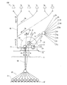
- a contaminated air recovery apparatus according to the present invention comprises an air collecting section 10A, a main control section 20, a discharging section 30, and the air collecting section 10A. And a suction-side air supply pipe 40 connecting between the main control unit 20 and the delivery-side air supply pipe 50 connecting between the main control unit 20 and the discharge unit 30.
- reference numerals 1a to 1f denote areas where the air collecting unit 10A is installed, and include a residential area 1a with a large traffic volume, a main road area 1b, a traffic congestion frequently area 1c, an industrial plant area 1d, an urban air pollution time zone 1e, An area 1f with a large amount of dust scattering harmful substance particles is exemplified.
- Reference numeral 1g denotes a contaminated air path directly introduced into the main control unit 20 without passing through the suction-side air supply pipe 40
- reference numeral S denotes a sea surface
- reference numeral SF denotes a seabed.
- FIG. 2 is a vertical cross-sectional view of the air collecting unit 10A
- FIG. 3 is a bottom view of the air collecting unit 10A
- the air collecting unit 10A has a bowl-shaped cover body 11A having a downward opening, and a cover body 11A. It has a filter member 12 attached inside and a mesh member 13 stretched below the filter member 12, and removes air pollutants such as, for example, on the road where automobiles pass or near industrial facilities such as factories and plants. It is installed in a contaminated air atmosphere where the contaminated air PA containing the air exists.
- a flange is provided inside the cover body 11A in which the suction side air supply pipe 40 whose upper side is opened extends in an umbrella shape from the periphery of the opening downward so that the opening substantially coincides with the center line of the cover body 11A. 41, and a vent 42 is formed in the flange 41.
- the filter member 12 can use a conventionally known air cleaning filter formed of, for example, a nonwoven fabric or a glass fiber, and removes moisture and minute foreign matters in the sucked contaminated air PA. It is particularly desirable that they be interchangeably mounted.
- the mesh member 13 can use a conventionally well-known mesh formed of, for example, metal or synthetic fiber, and removes relatively large foreign matters and insects in the contaminated air PA, and is replaceably attached. Is particularly desirable.
- FIG. 4 is a schematic view showing the air collecting section 10A and the suction side air supply pipe 40.
- the suction side air supply pipe 40 is divided into a ground portion and a basement portion, and the ground portion stands up from the ground G by a predetermined height. For example, by setting the height close to the guardrail or pole (about 1 m), the purpose of suctioning contaminated air can be achieved while minimizing the risk of obstructing the view of a pedestrian or driver or hindering the landscape.
- a height (about 3 m) close to a streetlight may be set so that a wider range of contaminated air can be sucked.
- the suction-side air supply pipe 40 in the underground portion is directly connected to the main control unit 20 through the ground, but the use of existing plumbing equipment such as sewerage can reduce the labor for construction, and in particular, desirable.
- the suction-side air supply pipe 40 in the present embodiment has a self-supporting strength, and uses a metal pipe coated with an inner surface and an outer surface. It may be configured (not shown). Further, for example, in a place where there is enough space such as an industrial facility in a suburb, the suction side air supply pipe may be transmitted over the ground without being buried underground (not shown).
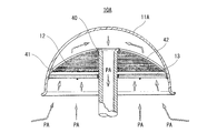
- FIG. 5 is a longitudinal sectional view of an air collecting portion 10B having a different shape
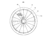
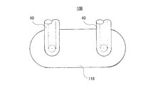
- FIG. 6 is a plan view of the air collecting portion 10B.
- the air collecting portion is connected to a point where the cover body 11B has a rectangular shape in plan view and the cover body 11B.
- the point that the number of suction side air supply pipes 40 is two is different from the air collection part 10A shown in FIGS. 1 to 4.
- the suction side air supply pipe 40 in the air collecting portion 10B is opened downward and integrated with the cover body 11B, the mesh member 13, the filter member 12, the filter member 12, and the like from the opening of the cover body 11B.
- the contaminated air PA sucked through the vents 15 of the support 14 in order is smoothly guided to the suction side air supply pipe 40 without reversing the flow direction.
- the support 14 has a plurality of ventilation holes 15, a rounded rectangular shape in plan view and an arc shape in vertical cross section, and is used for mounting the filter member 12.
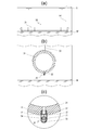
- FIG. 7 is a view showing a trap 60 mounted on the path of the suction side air supply pipe 40. As shown in this figure, a part of the trap 60 is bent so as to protrude downward. The discharge hole 43 is formed so as to penetrate therethrough, and the trap member 61 is externally attached so as to cover the discharge hole 43.
- the trap 60 is for dropping and collecting moisture and minute foreign substances contained in the contaminated air PA transported through the suction side air supply pipe 40 into the trap member 61, and penetrates the lower surface of the trap member 61. By removing the drain screw 63 screwed into the formed drain hole 62, accumulated water and minute foreign matter can be discharged from the drain hole 62.
- the main control unit 20 has the pump 21 that can suction and send out gas.
- the pump 21 a conventionally well-known pump can be used, and the type thereof is not limited.
- the main control unit 20 When the main control unit 20 is provided with a purification facility capable of purifying the contaminated air PA, for example, it purifies air pollutants derived from exhaust gas such as sulfur oxides and nitrogen oxides contained in the contaminated air PA to some extent. Then, it can be transported to the discharge section 30, which is more desirable for the marine environment (not shown).
- a purification facility capable of purifying the contaminated air PA, for example, it purifies air pollutants derived from exhaust gas such as sulfur oxides and nitrogen oxides contained in the contaminated air PA to some extent. Then, it can be transported to the discharge section 30, which is more desirable for the marine environment (not shown).
- the contaminated air PA that has passed through the pump 21 of the main control unit 20 is transported through the air supply pipe 50 and is supplied to the discharge unit 30.
- an impeller for sucking gas from the air collection unit 10 toward the discharge unit 30 is provided in the suction side air supply pipe 40 or the delivery side air supply pipe 50, and the impeller is driven by, for example, electric power.
- the impeller may be rotated to assist the pump 21 (not shown).
- FIG. 8 is a view showing the discharge unit 30, wherein the discharge unit 30 is a hollow cylindrical air storage container 31 installed at the sea and closed at both ends, and a lower surface of the air storage tube 31.
- a cap body 71 having a hollow bottom and a through-hole 72 formed in a peripheral wall connected to each of the jet ports 32 such that an opening top surrounds the jet port 32;
- a pressure adjusting cap 70 includes a valve seat 73 provided in the cap main body 71 and a float valve 74 built in the cap main body 71 and seated on the valve seat 73 by buoyancy and capable of closing the jet port 32. Have been.
- the float valve 74 separates from the valve seat 73, and the opened jet port 32 is opened.
- a predetermined amount of contaminated air PA is discharged from the cap body 71 through the through hole 72, and the inside of the air storage tube 31 is always maintained at a predetermined pressure.
- the inside of the air storage pipe 31 is always maintained at a predetermined pressure, and the contaminated air PA is supplied any more.
- the air PA is released into the sea, a certain amount of the contaminated air PA can be easily released without any control.
- the use of the float valve-type pressure adjusting cap allows the internal pressure of the air storage tube 31 to be a predetermined pressure due to the balance between the pressure in the air storage tube 31 and the buoyancy applied to the float valve 74.
- the ejection port 32 is formed above the air storage pipe 31 and a pressure adjusting cap is formed by a check valve such as a lift valve. (Not shown).
- the air storage tube 31 is provided with a simultaneous discharge means, it reacts to the occurrence of a tsunami or the like and simultaneously blows out the contaminated air PA stored in the air storage tube 31 to thereby cause the air storage tube 31 to emit.
- the upper sea area is a bubble-filled sea area, and the waves having high mass transport energy that successively rush into the bubble-filled sea area compress the bubbles to absorb the energy, so the energy of the waves is reduced before reaching the coastal part And contribute to disaster prevention.
- Patent Document 4 Japanese Patent Application Laid-Open No. 2015-86675
- the discharge amount of the contaminated air PA from the air storage pipe 31 is increased by rapidly increasing the flow rate of the contaminated air PA sent from the pump 21. Can be released all at once.
- the air storage pipe 31 is attached so as to be rotatable about its axis.
- the jet port 32 faces the sea surface and the float valve 74 is rotated. Is always separated from the valve seat 73, so that the contaminated air PA inside the air storage tube 31 can be discharged simultaneously (not shown).
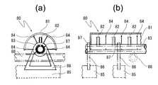
- FIG. 9 is a view showing a different discharge unit 80 of the present invention.
- the discharge unit 80 is a semi-cylindrical air storage container 81 which is installed in the sea and has both ends closed, and an air storage container 81 of the air storage container 81.
- An air supply pipe 83 having a plurality of ejection ports 82 formed on an upper surface thereof for supplying air to the inside; a beam 84 for connecting the air storage vessel 81 and the air supply pipe 83; It has a weight 85 for fixing the 80, a leg 86 erected from the weight 85, and a splittable annular fixing portion 87 for fixing the leg 86 and the air supply pipe 83.
- the delivery-side air supply pipe 50 and the air supply pipe 83 communicate with each other, and the contaminated air PA delivered from the ground passes through the delivery-side air supply pipe 50, passes through the air supply pipe 83 and the jet port 82, and stores the air. It is supplied to the container 81.
- the amount of the contaminated air PA stored in the air storage container 81 is always kept at a constant amount, and the contaminated air PA is supplied any more, and the surplus contaminated air PA exceeding a predetermined capacity is automatically introduced into the sea.
- a certain amount of the contaminated air PA can be easily discharged without any control.
- an air distribution pipe 88 communicating with each of the air supply pipes 83 is used.
- the air distribution pipe 88 communicates with the delivery-side air supply pipe 50, and the contaminated air PA delivered from the ground can be easily distributed to each of the air supply pipes 83 through the air distribution pipe 88. .
- FIG. 10 is a view showing still another discharge part 90 of the present invention.
- the discharge part 90 is a hollow cylindrical air storage container 91 installed in the sea, the air storage pipe 91 having both ends closed, and the air storage part 91.
- a plurality of second outlets 92 formed in a pair on the upper surface of the pipe 91 at an equal angle with respect to the axis of the air reservoir 91, and the air reservoir provided on an outer end surface of the second outlet 92.
- the delivery side air supply pipe 50 and the air supply pipe 94 are in communication with each other, and the contaminated air PA delivered from the ground passes through the delivery side air supply pipe 50 and the first outlet 95 of the air supply pipe 94.
- the air is supplied to the air storage pipe 91.
- the inside of the air storage pipe 91 exceeds a predetermined pressure due to the contaminated air PA supplied to the air storage pipe 91 through the first outlet 95 of the air supply pipe 94 via the delivery-side air supply pipe 50.
- the check valve 93 provided in the second ejection port 92 is pushed up to open the valve, and the contaminated air PA is discharged from the second ejection port 92 into the sea.
- the inside of the air storage pipe 91 is always maintained at a predetermined pressure, and the contaminated air PA is supplied any more.
- the air PA is released into the sea, a certain amount of the contaminated air PA can be easily released without any control.
- the discharge portion 90 has a double pipe structure including the outer air storage pipe 91 and the inner air supply pipe 94, the second ejection port is opened when the check valve 93 is opened. Even if seawater W intrudes into the air storage pipe 91 from 92, it does not affect the function.
- the air storage pipe 91 of the discharge section 90 and the air storage pipe 31 of the discharge section 30 shown in FIG. 1 are both cylindrical pipes whose both ends are closed, the inside of the pipe is underwater. There is an advantage that the function is not affected by the attachment of living things.
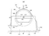
- FIGS. 11 to 13 are views showing still another discharge part 100 of the present invention, wherein the discharge part 100 is a semi-cylindrical air storage container 101 which is installed in the sea and has both ends closed, A weight 111 rotatably supported by rotating shafts 102, 102 projecting from the side walls at both ends along the central axis of the air storage container 101 and holding the air storage container 101 near the sea floor SF; 101, an air supply pipe 121 for supplying air to the inside of the container 101, a rotation control float 131 for keeping the opening 103 of the air storage container 101 in an upright state in the direction of the sea floor SF, and held near the sea floor SF.
- a wave detection float 141 disposed near the sea surface S at a predetermined horizontal distance from the air storage container 101, the wave detection float 141, and the air storage container Composed of air reservoir rotating wire 151 which connects a peripheral wall 108 of the 01.
- the opening 103 of the air storage container 101 is formed below the central axis of the air storage container 101.
- the air storage container 101 is disposed depending on the opening area, shape, quantity, etc. of the opening 103.
- the timing and amount of the stored gas to be blown up can be adjusted according to the water depth to be performed, and the strength of the air storage container 101 can also be adjusted.
- the rotating shafts 102, 102 are arranged along the central axis of the air storage container 101, and have both ends airtightly protruded from the side plates 104, 104 on both sides of the air storage container 101 by a predetermined length.
- the center shaft 105 penetrates through the side plates 104 on both sides of the air storage container 101 and is disposed in the air storage container 101 in the longitudinal direction. , 102 and the strength of the air storage container 101 are enhanced.
- the air storage container 101 is formed with a reinforcing plate 107 having substantially the same shape as the side plate 104 having a through hole 106 at a center position in the longitudinal direction thereof, in order to prevent breakage due to water pressure when placed in the sea.
- the contaminated air PA which is reinforced and stored, can be distributed inside the air storage container 101 through the through hole 106.
- the air storage container 101 is arranged near the sea floor SF so that the central axis is horizontal.
- the weight 111 that horizontally supports the air storage container 101 with the opening 103 facing the seabed SF has a substantially box-like shape with a trapezoidal shape in a side view and an open upper surface, and is formed of, for example, concrete.
- the weight body 112 having a weight body 112 installed on the seafloor SF and a shaft hole 113 that rotatably supports the air storage container 101 horizontally above the weight body 112 and through the rotation shaft 102.
- the weight body 112 is capable of holding the air storage container 101 storing at least the contaminated air PA therein on a seabed SF having a predetermined depth against its buoyancy. Requires fixing force (withstand load).
- wedge piles 116 fixed to the sea floor SF are arranged at four corners of the bottom surface 115, and the weight 111 can be more firmly installed on the sea floor SF. Even if the SF is inclined, there is no risk of slipping.
- a pair of sea surface wave detection floats 142 and a pair of sea surface wave detection floats 142 that float at the both ends in the longitudinal direction of the peripheral wall 108 of the air storage container 101 while reacting in the sea surface and in the sea at the same time.
- the wire 151 for rotating the air storage container, to which the wave detection float 141 composed of the float 143 is connected, is connected via a weight 152 with a pulley directly below and a weight 153 with a pulley on the way installed on the sea floor SF.
- the pair of sea surface wave detection floats 142 and the undersea wave detection floats 143 minimize the effects of strong offshore winds, swelling waves, and the like, and reliably respond to the rise of seawater due to waves and tsunamis and are greatly pushed up. It has a streamlined, disk-like shape.
- a total of two horizontal maintenance wires 132 are attached to the wire attachment portions 135 provided at both longitudinal ends of the peripheral wall 108 corresponding to the top of the air storage container 101.
- the air storage container 101 is held by the rotation control float 131 with the opening 103 facing the sea floor SF, and the air storage that needs to maintain the levelness to hold the contaminated air PA lying down is held.
- the opening 103 of the container 101 is a mechanism that can maintain stability in normal times.
- the air storage container 101 is moved by the fore-air rotation control float 131 so that the opening 103 is directed in the seafloor SF direction.
- the contaminated air PA can be sent from the air supply pipe 121 into the air storage container 101 again.
- the wave detection float 141 does not operate due to no wave, when the amount of the contaminated air PA supplied to the air storage container 101 via the air supply pipe 121 exceeds a predetermined capacity. The contaminated air PA is released into the sea from the periphery of the opening 103.
- the horizontal maintenance wire 132 connected to the rotation control float 131 has an adverse effect such that the wave detection float 141 rises when a wave arrives and prevents the air storage container rotation wire 151 from operating effectively. Absent.
- the mounting position of the wire 151 for rotating the air storage container is opposite to the wire mounting portions 135 at both ends of the top of the peripheral wall 108 of the air storage container 101 or the wave detection float 141 on the peripheral wall 108 of the air storage container 101. It can be selected from the wire mounting portion 145 corresponding to the side, and can be easily adjusted, for example, when it is desired to adjust the angle of rotation of the opening 103 according to the terrain or the water depth where the air storage container 101 is installed. Can be.
- Reference numeral 122 denotes a passage formed in the weight main body 112 of the weight 111 to allow the air supply pipe 121 to pass therethrough.
- the contaminated air PA ejected from the outlet 123 of the passage 122 receives the air from the opening 103 through the air reservoir. It is stored in the container 101.
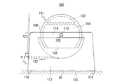
- FIG. 14 is a view showing a discharge section 160 in which a buoyancy chamber 162 is provided on the inner upper surface and an air storage container 161 having a double structure is attached to the weight 111 shown in FIGS.
- the same components as those of the discharge unit 130 are denoted by the same reference numerals.
- the air storage container 161 installed in the sea automatically assumes the posture in which the opening 103 is directed to the sea floor SF side by the buoyancy of the buoyancy chamber 162, so that various floats need to be used. There is no.
- the contaminated air PA flows from the periphery of the opening 103 into the sea. Is to be released.
- the opening 103 of the air storage container 161 can be rotated upward by predetermined urging means or the like, and the contaminated air PA stored inside can be simultaneously released. After the discharge, the air storage container 161 automatically returns to the posture in which the opening 103 is directed toward the sea floor SF by the buoyancy of the buoyancy chamber 162.
- FIG. 15 is a view showing a different embodiment of the present invention, which is different from the embodiment shown in FIG. 1 in that both the contaminated air PA and the normal air A can be used.
- reference numeral 2a denotes a path for introducing normal air A.
- the air collecting unit 10A similar to the embodiment shown in FIG. It is installed and recovers normal air A, and is introduced into the main control unit 20.
- the normal air A is transported by the pump 20 of the main control unit 21 to the discharge unit 30 in the same manner as the flow of the contaminated air PA by the delivery air supply pipe 50.
- the concentration of the contaminated air PA is reduced, which is not only more desirable for the marine environment but also the air supplied to the air storage pipe 31. Since the amount can be secured, it is possible to more easily operate the simultaneous release means when a tsunami or the like occurs.
- the normal air A collected from the air collecting unit 10A normally arranged in the normal air atmosphere may be supplied to each area or facility requiring the normal air A, for example, as shown in FIG. Public facilities 3a, schoolchildren's facilities 3b, park athletic grounds 3c, stadiums 3d, city streets 3e, exhibition halls 3f, hospital medical facilities 3g, public halls 3h, ballparks 3i, temporary supply bases 3j, etc., which are designated by reference numerals 3a to 3j. Can be
- the air storage container has a simultaneous release means
- the gas inside the air storage container is simultaneously released in the event of a tsunami or an emergency to generate air bubbles, thereby generating an air storage container. It can also reduce the mass transport energy of the tsunami passing above it to reduce the damage and prevent the intrusion of ships.
Landscapes
- Chemical & Material Sciences (AREA)
- Engineering & Computer Science (AREA)
- Environmental & Geological Engineering (AREA)
- Chemical Kinetics & Catalysis (AREA)
- Biomedical Technology (AREA)
- Health & Medical Sciences (AREA)
- Analytical Chemistry (AREA)
- General Chemical & Material Sciences (AREA)
- Oil, Petroleum & Natural Gas (AREA)
- Dispersion Chemistry (AREA)
- Organic Chemistry (AREA)
- Life Sciences & Earth Sciences (AREA)
- Geology (AREA)
- Treating Waste Gases (AREA)
- Physical Or Chemical Processes And Apparatus (AREA)
Abstract
L'invention concerne un dispositif de récupération d'air pollué, avec lequel il est possible de récupérer facilement de l'air pollué sur une large zone et de rendre la zone inoffensive. Ce dispositif comprend une unité de collecte d'air 10A, une unité de commande principale 20, une unité d'émission 30, et un tuyau d'air côté aspiration 40 et un tuyau d'air côté distribution 50. L'unité de collecte d'air 10A comprend un corps de couvercle 11A ayant une ouverture sur le côté inférieur de celui-ci et un élément filtrant 12 fixé à l'intérieur du corps de couvercle 11A. L'unité de commande principale 20 comporte une pompe 21 apte à aspirer du gaz par aspiration et à le délivrer. L'unité d'émission 30 a un tuyau de stockage d'air 31 à installer sous-marin et une pluralité de buses d'échappement 32 disposées sur le tuyau de stockage d'air 31. Le tuyau d'air côté aspiration 40 relie l'unité de collecte d'air 10 et l'unité de commande principale 20. Le tuyau d'air côté distribution 50 relie l'unité de commande principale 20 et l'unité d'émission 30 de façon à permettre au gaz de se déplacer entre eux. Le gaz, qui est l'air pollué PA, est aspiré par l'unité de collecte d'air 10A par la pompe 21 et est délivré à l'unité d'émission 30, puis est déchargé des buses d'échappement 32 du tuyau de stockage d'air 31.
Priority Applications (2)
| Application Number | Priority Date | Filing Date | Title |
|---|---|---|---|
| JP2020527687A JP7229562B2 (ja) | 2018-06-28 | 2019-06-28 | 汚染空気の回収装置 |
| US17/256,173 US20210354082A1 (en) | 2018-06-28 | 2019-06-28 | Device for recovering polluted air |
Applications Claiming Priority (2)
| Application Number | Priority Date | Filing Date | Title |
|---|---|---|---|
| JP2018123682 | 2018-06-28 | ||
| JP2018-123682 | 2018-06-28 |
Publications (1)
| Publication Number | Publication Date |
|---|---|
| WO2020004629A1 true WO2020004629A1 (fr) | 2020-01-02 |
Family
ID=68987163
Family Applications (1)
| Application Number | Title | Priority Date | Filing Date |
|---|---|---|---|
| PCT/JP2019/025855 Ceased WO2020004629A1 (fr) | 2018-06-28 | 2019-06-28 | Dispositif de récupération d'air pollué |
Country Status (3)
| Country | Link |
|---|---|
| US (1) | US20210354082A1 (fr) |
| JP (1) | JP7229562B2 (fr) |
| WO (1) | WO2020004629A1 (fr) |
Citations (7)
| Publication number | Priority date | Publication date | Assignee | Title |
|---|---|---|---|---|
| JPS63315717A (ja) * | 1987-06-19 | 1988-12-23 | Tomoji Ono | 消波装置 |
| JPH11262630A (ja) * | 1998-03-17 | 1999-09-28 | Kenji Horii | 炭酸ガス等除去方法およびその装置 |
| JP2005342656A (ja) * | 2004-06-04 | 2005-12-15 | Nakajima Kogyo:Kk | 気体成分を海洋の深層域に溶入させる方法および装置 |
| JP2014020188A (ja) * | 2012-07-12 | 2014-02-03 | Hiromitsu Tejima | 津波の質量輸送エネルギーを緩和する装置 |
| JP2015086675A (ja) * | 2013-10-31 | 2015-05-07 | 浩光 手島 | 高波津波を防災減災するために特定海域を気泡充満海域にするシステム |
| CN107524111A (zh) * | 2017-08-25 | 2017-12-29 | 无锡厚发自动化设备有限公司 | 一种采用气幕式防波堤对堤岸进行防护的方法 |
| JP2018115482A (ja) * | 2017-01-18 | 2018-07-26 | 有限会社手島通商 | 津波の質量輸送エネルギー緩和装置 |
Family Cites Families (9)
| Publication number | Priority date | Publication date | Assignee | Title |
|---|---|---|---|---|
| JPS5518105Y2 (fr) * | 1972-10-20 | 1980-04-25 | ||
| JP2645786B2 (ja) * | 1992-12-08 | 1997-08-25 | 勲 堀内 | 空気浄化方法およびその装置 |
| JPH1066988A (ja) * | 1996-08-28 | 1998-03-10 | Matsushita Electric Works Ltd | 浄化槽の散気装置 |
| JP2005307833A (ja) | 2004-04-20 | 2005-11-04 | Toyota Motor Corp | 排ガス浄化装置 |
| JP4704881B2 (ja) | 2005-10-13 | 2011-06-22 | ダイセン・メンブレン・システムズ株式会社 | 散気装置 |
| JP5751743B2 (ja) * | 2009-03-09 | 2015-07-22 | 三菱重工業株式会社 | 排ガス処理装置及び排ガス処理方法 |
| US20120220019A1 (en) * | 2009-07-23 | 2012-08-30 | Lackner Klaus S | Air collector with functionalized ion exchange membrane for capturing ambient co2 |
| GB2477181A (en) * | 2010-01-22 | 2011-07-27 | Plymouth Marine Lab | Marine based carbon sequestration device and methods |
| EP2800621A4 (fr) * | 2012-01-06 | 2015-09-23 | Univ Columbia | Procédés et systèmes de capture et de stockage de dioxyde de carbone |
-
2019
- 2019-06-28 WO PCT/JP2019/025855 patent/WO2020004629A1/fr not_active Ceased
- 2019-06-28 US US17/256,173 patent/US20210354082A1/en not_active Abandoned
- 2019-06-28 JP JP2020527687A patent/JP7229562B2/ja active Active
Patent Citations (7)
| Publication number | Priority date | Publication date | Assignee | Title |
|---|---|---|---|---|
| JPS63315717A (ja) * | 1987-06-19 | 1988-12-23 | Tomoji Ono | 消波装置 |
| JPH11262630A (ja) * | 1998-03-17 | 1999-09-28 | Kenji Horii | 炭酸ガス等除去方法およびその装置 |
| JP2005342656A (ja) * | 2004-06-04 | 2005-12-15 | Nakajima Kogyo:Kk | 気体成分を海洋の深層域に溶入させる方法および装置 |
| JP2014020188A (ja) * | 2012-07-12 | 2014-02-03 | Hiromitsu Tejima | 津波の質量輸送エネルギーを緩和する装置 |
| JP2015086675A (ja) * | 2013-10-31 | 2015-05-07 | 浩光 手島 | 高波津波を防災減災するために特定海域を気泡充満海域にするシステム |
| JP2018115482A (ja) * | 2017-01-18 | 2018-07-26 | 有限会社手島通商 | 津波の質量輸送エネルギー緩和装置 |
| CN107524111A (zh) * | 2017-08-25 | 2017-12-29 | 无锡厚发自动化设备有限公司 | 一种采用气幕式防波堤对堤岸进行防护的方法 |
Also Published As
| Publication number | Publication date |
|---|---|
| JPWO2020004629A1 (ja) | 2021-08-02 |
| JP7229562B2 (ja) | 2023-02-28 |
| US20210354082A1 (en) | 2021-11-18 |
Similar Documents
| Publication | Publication Date | Title |
|---|---|---|
| KR100590838B1 (ko) | 부유 오염물질 분리방법 및 분리장치 | |
| CN107930299B (zh) | 微尘清除装置 | |
| KR102746139B1 (ko) | 여과, 정수, 정화 기능을 가진 밸브실 | |
| CN109944313B (zh) | 一种农村室外真空排水系统 | |
| CN104631547A (zh) | 雨水收集系统 | |
| JP2010131559A (ja) | 大気汚染浄化装置 | |
| KR101152571B1 (ko) | 하수관로 냄새 제거 시스템 | |
| KR101611507B1 (ko) | 해상 처분장에 설치되는 집수관 및 집수관 설치방법 | |
| KR20160060012A (ko) | 하천수에 함유된 미립자성 오염물질들, 각종 쓰레기들 및 유체성 오염물질분자들을 완벽하게 제거함과 동시에 깨끗한 물로 정수하여 전기를 생산하는 자연친화적인 수질 정화기 겸용 친환경 발전 시스템 | |
| KR102368680B1 (ko) | 건축용 소방수 급배수 장치 | |
| KR101829041B1 (ko) | 물리적 충격과 산기형 지하수의 라돈 저감 장치 | |
| WO2020004629A1 (fr) | Dispositif de récupération d'air pollué | |
| KR20130020101A (ko) | 건물 1층의 바닥 하부 공간을 활용한 실내 라돈 저감장치 및 설치 공법 | |
| CN113187067B (zh) | 基于雨污分流市政道路初期雨水收集装置 | |
| US20220249730A1 (en) | Method and device for capturing and disinfecting contaminants for drainage system | |
| CZ302995A3 (en) | Engineering structure for built-up structures made of reinforced concrete or the like material | |
| JP6579473B2 (ja) | 放水装置 | |
| KR102112839B1 (ko) | 산불예방을 위한 방화수 생산 기능의 사방댐 시스템 | |
| WO2023038302A1 (fr) | Procédé de fabrication d'un appareil de génération de tourbillon de vent destiné à la purification de l'air contaminé | |
| JP6085861B2 (ja) | マンホールの突き上げ浮上防止方法 | |
| WO2009101631A1 (fr) | Procédé de construction de bâtiment et bâtiments résultants | |
| CN219886487U (zh) | 一种市政道路排水系统 | |
| CN209098220U (zh) | 用于农药生产的污水净化池防护棚 | |
| KR20230002121A (ko) | 중력식 공해정화배출기 제작방법 | |
| JPH11188225A (ja) | 汚染空気浄化装置 |
Legal Events
| Date | Code | Title | Description |
|---|---|---|---|
| 121 | Ep: the epo has been informed by wipo that ep was designated in this application |
Ref document number: 19827395 Country of ref document: EP Kind code of ref document: A1 |
|
| ENP | Entry into the national phase |
Ref document number: 2020527687 Country of ref document: JP Kind code of ref document: A |
|
| NENP | Non-entry into the national phase |
Ref country code: DE |
|
| 122 | Ep: pct application non-entry in european phase |
Ref document number: 19827395 Country of ref document: EP Kind code of ref document: A1 |