WO2020004633A1 - 認証体、認証体の製造方法、認証体の読み取り方法、および認証体の検証方法 - Google Patents
認証体、認証体の製造方法、認証体の読み取り方法、および認証体の検証方法 Download PDFInfo
- Publication number
- WO2020004633A1 WO2020004633A1 PCT/JP2019/025868 JP2019025868W WO2020004633A1 WO 2020004633 A1 WO2020004633 A1 WO 2020004633A1 JP 2019025868 W JP2019025868 W JP 2019025868W WO 2020004633 A1 WO2020004633 A1 WO 2020004633A1
- Authority
- WO
- WIPO (PCT)
- Prior art keywords
- check data
- personal identification
- identification information
- hologram
- information
- Prior art date
- Legal status (The legal status is an assumption and is not a legal conclusion. Google has not performed a legal analysis and makes no representation as to the accuracy of the status listed.)
- Ceased
Links
Images









Classifications
-
- B—PERFORMING OPERATIONS; TRANSPORTING
- B42—BOOKBINDING; ALBUMS; FILES; SPECIAL PRINTED MATTER
- B42D—BOOKS; BOOK COVERS; LOOSE LEAVES; PRINTED MATTER CHARACTERISED BY IDENTIFICATION OR SECURITY FEATURES; PRINTED MATTER OF SPECIAL FORMAT OR STYLE NOT OTHERWISE PROVIDED FOR; DEVICES FOR USE THEREWITH AND NOT OTHERWISE PROVIDED FOR; MOVABLE-STRIP WRITING OR READING APPARATUS
- B42D25/00—Information-bearing cards or sheet-like structures characterised by identification or security features; Manufacture thereof
- B42D25/20—Information-bearing cards or sheet-like structures characterised by identification or security features; Manufacture thereof characterised by a particular use or purpose
- B42D25/23—Identity cards
-
- G—PHYSICS
- G06—COMPUTING OR CALCULATING; COUNTING
- G06K—GRAPHICAL DATA READING; PRESENTATION OF DATA; RECORD CARRIERS; HANDLING RECORD CARRIERS
- G06K19/00—Record carriers for use with machines and with at least a part designed to carry digital markings
- G06K19/06—Record carriers for use with machines and with at least a part designed to carry digital markings characterised by the kind of the digital marking, e.g. shape, nature, code
- G06K19/06009—Record carriers for use with machines and with at least a part designed to carry digital markings characterised by the kind of the digital marking, e.g. shape, nature, code with optically detectable marking
- G06K19/06046—Constructional details
- G06K19/06065—Constructional details the marking being at least partially represented by holographic means
-
- B—PERFORMING OPERATIONS; TRANSPORTING
- B42—BOOKBINDING; ALBUMS; FILES; SPECIAL PRINTED MATTER
- B42D—BOOKS; BOOK COVERS; LOOSE LEAVES; PRINTED MATTER CHARACTERISED BY IDENTIFICATION OR SECURITY FEATURES; PRINTED MATTER OF SPECIAL FORMAT OR STYLE NOT OTHERWISE PROVIDED FOR; DEVICES FOR USE THEREWITH AND NOT OTHERWISE PROVIDED FOR; MOVABLE-STRIP WRITING OR READING APPARATUS
- B42D13/00—Loose leaves modified for binding; Inserts
-
- B—PERFORMING OPERATIONS; TRANSPORTING
- B42—BOOKBINDING; ALBUMS; FILES; SPECIAL PRINTED MATTER
- B42D—BOOKS; BOOK COVERS; LOOSE LEAVES; PRINTED MATTER CHARACTERISED BY IDENTIFICATION OR SECURITY FEATURES; PRINTED MATTER OF SPECIAL FORMAT OR STYLE NOT OTHERWISE PROVIDED FOR; DEVICES FOR USE THEREWITH AND NOT OTHERWISE PROVIDED FOR; MOVABLE-STRIP WRITING OR READING APPARATUS
- B42D25/00—Information-bearing cards or sheet-like structures characterised by identification or security features; Manufacture thereof
- B42D25/30—Identification or security features, e.g. for preventing forgery
- B42D25/305—Associated digital information
-
- B—PERFORMING OPERATIONS; TRANSPORTING
- B42—BOOKBINDING; ALBUMS; FILES; SPECIAL PRINTED MATTER
- B42D—BOOKS; BOOK COVERS; LOOSE LEAVES; PRINTED MATTER CHARACTERISED BY IDENTIFICATION OR SECURITY FEATURES; PRINTED MATTER OF SPECIAL FORMAT OR STYLE NOT OTHERWISE PROVIDED FOR; DEVICES FOR USE THEREWITH AND NOT OTHERWISE PROVIDED FOR; MOVABLE-STRIP WRITING OR READING APPARATUS
- B42D25/00—Information-bearing cards or sheet-like structures characterised by identification or security features; Manufacture thereof
- B42D25/30—Identification or security features, e.g. for preventing forgery
- B42D25/328—Diffraction gratings; Holograms
-
- B—PERFORMING OPERATIONS; TRANSPORTING
- B42—BOOKBINDING; ALBUMS; FILES; SPECIAL PRINTED MATTER
- B42D—BOOKS; BOOK COVERS; LOOSE LEAVES; PRINTED MATTER CHARACTERISED BY IDENTIFICATION OR SECURITY FEATURES; PRINTED MATTER OF SPECIAL FORMAT OR STYLE NOT OTHERWISE PROVIDED FOR; DEVICES FOR USE THEREWITH AND NOT OTHERWISE PROVIDED FOR; MOVABLE-STRIP WRITING OR READING APPARATUS
- B42D25/00—Information-bearing cards or sheet-like structures characterised by identification or security features; Manufacture thereof
- B42D25/40—Manufacture
- B42D25/45—Associating two or more layers
- B42D25/455—Associating two or more layers using heat
-
- B—PERFORMING OPERATIONS; TRANSPORTING
- B42—BOOKBINDING; ALBUMS; FILES; SPECIAL PRINTED MATTER
- B42D—BOOKS; BOOK COVERS; LOOSE LEAVES; PRINTED MATTER CHARACTERISED BY IDENTIFICATION OR SECURITY FEATURES; PRINTED MATTER OF SPECIAL FORMAT OR STYLE NOT OTHERWISE PROVIDED FOR; DEVICES FOR USE THEREWITH AND NOT OTHERWISE PROVIDED FOR; MOVABLE-STRIP WRITING OR READING APPARATUS
- B42D25/00—Information-bearing cards or sheet-like structures characterised by identification or security features; Manufacture thereof
- B42D25/40—Manufacture
- B42D25/45—Associating two or more layers
- B42D25/46—Associating two or more layers using pressure
-
- B—PERFORMING OPERATIONS; TRANSPORTING
- B42—BOOKBINDING; ALBUMS; FILES; SPECIAL PRINTED MATTER
- B42D—BOOKS; BOOK COVERS; LOOSE LEAVES; PRINTED MATTER CHARACTERISED BY IDENTIFICATION OR SECURITY FEATURES; PRINTED MATTER OF SPECIAL FORMAT OR STYLE NOT OTHERWISE PROVIDED FOR; DEVICES FOR USE THEREWITH AND NOT OTHERWISE PROVIDED FOR; MOVABLE-STRIP WRITING OR READING APPARATUS
- B42D25/00—Information-bearing cards or sheet-like structures characterised by identification or security features; Manufacture thereof
- B42D25/40—Manufacture
- B42D25/48—Controlling the manufacturing process
- B42D25/485—Controlling the manufacturing process by electronic processing means
-
- G—PHYSICS
- G03—PHOTOGRAPHY; CINEMATOGRAPHY; ANALOGOUS TECHNIQUES USING WAVES OTHER THAN OPTICAL WAVES; ELECTROGRAPHY; HOLOGRAPHY
- G03H—HOLOGRAPHIC PROCESSES OR APPARATUS
- G03H1/00—Holographic processes or apparatus using light, infrared or ultraviolet waves for obtaining holograms or for obtaining an image from them; Details peculiar thereto
- G03H1/0005—Adaptation of holography to specific applications
- G03H1/0011—Adaptation of holography to specific applications for security or authentication
-
- G—PHYSICS
- G03—PHOTOGRAPHY; CINEMATOGRAPHY; ANALOGOUS TECHNIQUES USING WAVES OTHER THAN OPTICAL WAVES; ELECTROGRAPHY; HOLOGRAPHY
- G03H—HOLOGRAPHIC PROCESSES OR APPARATUS
- G03H1/00—Holographic processes or apparatus using light, infrared or ultraviolet waves for obtaining holograms or for obtaining an image from them; Details peculiar thereto
- G03H1/02—Details of features involved during the holographic process; Replication of holograms without interference recording
- G03H1/024—Hologram nature or properties
- G03H1/0244—Surface relief holograms
-
- G—PHYSICS
- G06—COMPUTING OR CALCULATING; COUNTING
- G06K—GRAPHICAL DATA READING; PRESENTATION OF DATA; RECORD CARRIERS; HANDLING RECORD CARRIERS
- G06K19/00—Record carriers for use with machines and with at least a part designed to carry digital markings
- G06K19/02—Record carriers for use with machines and with at least a part designed to carry digital markings characterised by the selection of materials, e.g. to avoid wear during transport through the machine
-
- G—PHYSICS
- G06—COMPUTING OR CALCULATING; COUNTING
- G06K—GRAPHICAL DATA READING; PRESENTATION OF DATA; RECORD CARRIERS; HANDLING RECORD CARRIERS
- G06K19/00—Record carriers for use with machines and with at least a part designed to carry digital markings
- G06K19/06—Record carriers for use with machines and with at least a part designed to carry digital markings characterised by the kind of the digital marking, e.g. shape, nature, code
-
- G—PHYSICS
- G07—CHECKING-DEVICES
- G07D—HANDLING OF COINS OR VALUABLE PAPERS, e.g. TESTING, SORTING BY DENOMINATIONS, COUNTING, DISPENSING, CHANGING OR DEPOSITING
- G07D7/00—Testing specially adapted to determine the identity or genuineness of valuable papers or for segregating those which are unacceptable, e.g. banknotes that are alien to a currency
- G07D7/06—Testing specially adapted to determine the identity or genuineness of valuable papers or for segregating those which are unacceptable, e.g. banknotes that are alien to a currency using wave or particle radiation
- G07D7/12—Visible light, infrared or ultraviolet radiation
-
- B—PERFORMING OPERATIONS; TRANSPORTING
- B42—BOOKBINDING; ALBUMS; FILES; SPECIAL PRINTED MATTER
- B42D—BOOKS; BOOK COVERS; LOOSE LEAVES; PRINTED MATTER CHARACTERISED BY IDENTIFICATION OR SECURITY FEATURES; PRINTED MATTER OF SPECIAL FORMAT OR STYLE NOT OTHERWISE PROVIDED FOR; DEVICES FOR USE THEREWITH AND NOT OTHERWISE PROVIDED FOR; MOVABLE-STRIP WRITING OR READING APPARATUS
- B42D25/00—Information-bearing cards or sheet-like structures characterised by identification or security features; Manufacture thereof
- B42D25/20—Information-bearing cards or sheet-like structures characterised by identification or security features; Manufacture thereof characterised by a particular use or purpose
- B42D25/24—Passports
-
- G—PHYSICS
- G03—PHOTOGRAPHY; CINEMATOGRAPHY; ANALOGOUS TECHNIQUES USING WAVES OTHER THAN OPTICAL WAVES; ELECTROGRAPHY; HOLOGRAPHY
- G03H—HOLOGRAPHIC PROCESSES OR APPARATUS
- G03H1/00—Holographic processes or apparatus using light, infrared or ultraviolet waves for obtaining holograms or for obtaining an image from them; Details peculiar thereto
- G03H1/02—Details of features involved during the holographic process; Replication of holograms without interference recording
- G03H1/024—Hologram nature or properties
- G03H1/0248—Volume holograms
-
- G—PHYSICS
- G03—PHOTOGRAPHY; CINEMATOGRAPHY; ANALOGOUS TECHNIQUES USING WAVES OTHER THAN OPTICAL WAVES; ELECTROGRAPHY; HOLOGRAPHY
- G03H—HOLOGRAPHIC PROCESSES OR APPARATUS
- G03H1/00—Holographic processes or apparatus using light, infrared or ultraviolet waves for obtaining holograms or for obtaining an image from them; Details peculiar thereto
- G03H1/26—Processes or apparatus specially adapted to produce multiple sub- holograms or to obtain images from them, e.g. multicolour technique
- G03H1/2645—Multiplexing processes, e.g. aperture, shift, or wavefront multiplexing
- G03H1/265—Angle multiplexing; Multichannel holograms
-
- G—PHYSICS
- G03—PHOTOGRAPHY; CINEMATOGRAPHY; ANALOGOUS TECHNIQUES USING WAVES OTHER THAN OPTICAL WAVES; ELECTROGRAPHY; HOLOGRAPHY
- G03H—HOLOGRAPHIC PROCESSES OR APPARATUS
- G03H1/00—Holographic processes or apparatus using light, infrared or ultraviolet waves for obtaining holograms or for obtaining an image from them; Details peculiar thereto
- G03H1/0005—Adaptation of holography to specific applications
- G03H1/0011—Adaptation of holography to specific applications for security or authentication
- G03H2001/0016—Covert holograms or holobjects requiring additional knowledge to be perceived, e.g. holobject reconstructed only under IR illumination
-
- G—PHYSICS
- G03—PHOTOGRAPHY; CINEMATOGRAPHY; ANALOGOUS TECHNIQUES USING WAVES OTHER THAN OPTICAL WAVES; ELECTROGRAPHY; HOLOGRAPHY
- G03H—HOLOGRAPHIC PROCESSES OR APPARATUS
- G03H1/00—Holographic processes or apparatus using light, infrared or ultraviolet waves for obtaining holograms or for obtaining an image from them; Details peculiar thereto
- G03H1/04—Processes or apparatus for producing holograms
- G03H1/0493—Special holograms not otherwise provided for, e.g. conoscopic, referenceless holography
- G03H2001/0497—Dot matrix holograms
-
- G—PHYSICS
- G03—PHOTOGRAPHY; CINEMATOGRAPHY; ANALOGOUS TECHNIQUES USING WAVES OTHER THAN OPTICAL WAVES; ELECTROGRAPHY; HOLOGRAPHY
- G03H—HOLOGRAPHIC PROCESSES OR APPARATUS
- G03H1/00—Holographic processes or apparatus using light, infrared or ultraviolet waves for obtaining holograms or for obtaining an image from them; Details peculiar thereto
- G03H1/26—Processes or apparatus specially adapted to produce multiple sub- holograms or to obtain images from them, e.g. multicolour technique
- G03H1/2645—Multiplexing processes, e.g. aperture, shift, or wavefront multiplexing
- G03H2001/266—Wavelength multiplexing
-
- G—PHYSICS
- G03—PHOTOGRAPHY; CINEMATOGRAPHY; ANALOGOUS TECHNIQUES USING WAVES OTHER THAN OPTICAL WAVES; ELECTROGRAPHY; HOLOGRAPHY
- G03H—HOLOGRAPHIC PROCESSES OR APPARATUS
- G03H2210/00—Object characteristics
- G03H2210/20—2D object
-
- G—PHYSICS
- G03—PHOTOGRAPHY; CINEMATOGRAPHY; ANALOGOUS TECHNIQUES USING WAVES OTHER THAN OPTICAL WAVES; ELECTROGRAPHY; HOLOGRAPHY
- G03H—HOLOGRAPHIC PROCESSES OR APPARATUS
- G03H2210/00—Object characteristics
- G03H2210/50—Nature of the object
- G03H2210/52—Alphanumerical
-
- G—PHYSICS
- G03—PHOTOGRAPHY; CINEMATOGRAPHY; ANALOGOUS TECHNIQUES USING WAVES OTHER THAN OPTICAL WAVES; ELECTROGRAPHY; HOLOGRAPHY
- G03H—HOLOGRAPHIC PROCESSES OR APPARATUS
- G03H2250/00—Laminate comprising a hologram layer
- G03H2250/10—Laminate comprising a hologram layer arranged to be transferred onto a carrier body
-
- G—PHYSICS
- G03—PHOTOGRAPHY; CINEMATOGRAPHY; ANALOGOUS TECHNIQUES USING WAVES OTHER THAN OPTICAL WAVES; ELECTROGRAPHY; HOLOGRAPHY
- G03H—HOLOGRAPHIC PROCESSES OR APPARATUS
- G03H2250/00—Laminate comprising a hologram layer
- G03H2250/42—Reflective layer
-
- G—PHYSICS
- G03—PHOTOGRAPHY; CINEMATOGRAPHY; ANALOGOUS TECHNIQUES USING WAVES OTHER THAN OPTICAL WAVES; ELECTROGRAPHY; HOLOGRAPHY
- G03H—HOLOGRAPHIC PROCESSES OR APPARATUS
- G03H2270/00—Substrate bearing the hologram
- G03H2270/52—Integrated surface relief hologram without forming layer
Definitions
- the embodiments of the present invention relate to an authenticator, an authenticator manufacturing method, an authenticator reading method, and an authenticator verifying method.
- This application claims priority to Japanese Patent Application No. 2018-124211 filed on June 29, 2018 and Japanese Patent Application No. 2018-204306 filed on October 30, 2018, and uses the contents thereof. I do.
- ID (IDentification) cards such as passports and driver's licenses are known as authenticators containing personal information.
- Many ID cards display a face image or character information in order to visually identify personal information. If the personal information is simply printed on the authenticating body, it can be easily falsified or forged.
- Patent Document 1 describes that the hologram transfer foil is applied to the authenticator to improve the tamper-proof property of the authenticator.
- Patent Literature 2 describes that a fluorescent light emitting material is used to add personal information so that it is transparent and invisible with visible light observation but is visible with ultraviolet light observation.
- Patent Literature 1 The forgery prevention technology described in Patent Literature 1 is, in addition to being widely known, a hologram that emits a simple rainbow-color diffracted light, and is easily forged.
- Patent Document 3 describes, as a further forgery prevention method, that authenticity is verified by irradiating a hologram with light having a specific wavelength and using reproduction information displayed on the hologram.
- JP-A-6-67592 Japanese Patent No. 3198324 Japanese Patent No. 4677683
- the reproduction information is designed in advance and is invariable. Therefore, if the forger learns the reproduction information, a hologram imitating the reproduction information may be produced, and there is still room for improvement.
- an embodiment of the present invention aims to provide an authentication body capable of suppressing tampering and forgery with a simple configuration, and a technology related to verification.
- the embodiments of the present invention are a group of embodiments based on a unique unitary invention from the background. Further, aspects of the present disclosure are aspects of a group of embodiments based on a single invention. Each configuration of the present disclosure may have each aspect of the present disclosure. As a solution of the present invention, the embodiment of the present invention has the following aspects. The aspects can be combined and the combination can achieve synergy. Also, each aspect can be combined with features of the embodiments, and the combination can provide synergy. Also, the features of the embodiments can be combined, and the combinations can achieve synergy.
- a first aspect of the present invention is a sheet-like laminate sheet, a first area formed on the laminate sheet, where the first individual information is recorded, and a first area formed on the laminate sheet and associated with the first individual information. And a second area having a hologram structure in which the individual information is recorded.
- a step of obtaining first individual information, a step of generating second individual information associated with the first individual information based on the first individual information, and A method for manufacturing an authenticator comprising: a step of recording on a laminate sheet; and a step of forming a hologram structure recording second individual information on the laminate sheet.
- a third aspect of the present invention is a method of reading an authenticator according to the present invention, which reads the authenticator.
- the method comprises the steps of: obtaining condition information indicating a condition for reproducing the second individual information in the hologram structure of the authenticator; and irradiating the hologram structure with light based on the condition information, thereby obtaining the second individual information. And a step of regenerating.
- a fourth aspect of the present invention is a method of verifying an authenticator according to the present invention, which determines the authenticity of the authenticator.
- This method includes the steps of reading the first individual information recorded on the authenticator, reading the second individual information recorded on the hologram structure of the authenticator, and reading the first individual information and the second individual information. Judging the authenticity of the authenticating body based on the authentication information.
- falsification and forgery can be suppressed with a simple configuration.
- FIG. 1 is a plan view conceptually illustrating an authentication body according to an embodiment of the present invention. It is a perspective view of the same authentication body.
- FIG. 4 is a diagram conceptually illustrating a reproduced image in a second area of the authentication body. It is a flowchart which shows the flow of the manufacturing method of the authentication body which concerns on the embodiment.
- FIG. 1 is a perspective view conceptually illustrating a hologram film used in an embodiment of the present invention.
- FIG. 4B is a cross-sectional view taken along the line II of FIG. 4A, which conceptually illustrates the position of a reproduced image. It is a flowchart explaining the verification method of the authentication body which concerns on the embodiment. It is a figure showing an example of a hologram structure.
- FIG. 3 is a diagram illustrating an example of a hologram structure including a plurality of unit cell regions.
- FIG. 3 is a diagram illustrating an example of a hologram structure including a plurality of unit cell regions.
- FIG. 3 is a diagram illustrating an example of a hologram structure including a plurality of unit cell regions.
- FIG. 3 is a diagram illustrating a hologram structure and a reproduction position of a reproduction image.
- FIG. 3 is a diagram illustrating an example of a hologram structure area in a unit cell area. It is a figure showing an example of a hologram structure field where a reflective layer is not completely removed.
- FIG. 3 is a diagram illustrating an example of a hologram structure area in a unit cell area.
- FIG. 3 is a diagram illustrating an example of a hologram structure area in a unit cell area.
- FIG. 3 is a diagram illustrating an example of a hologram structure area in a unit cell area.
- FIG. 3 is a diagram illustrating an example of a hologram structure area in a unit cell area.
- FIG. 3 is a diagram illustrating an example of a positional relationship between a hologram structure and a reproduction position of a reproduction image.
- FIG. 3 is a diagram illustrating an example of a positional relationship between a hologram structure and a reproduction position of a reproduction image.
- FIGS. 1 to 20 An embodiment of the present invention will be described with reference to FIGS. 1 to 20.
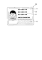
- FIG. 1 is a plan view of an authentication body 100 according to the present embodiment.
- the authentication body 1 includes a sheet-like laminate sheet 30 and a first area 11 and a second area 12 formed in a part of the laminate sheet 30.
- the authentication body can be a laminate.
- the laminate can be a card or a page.
- the laminate may be a laminate of a plurality of laminate sheets 30.
- the laminate sheet 30 can be a thermoplastic plastic sheet.
- the material of the laminate sheet 30 can be polycarbonate or vinyl chloride.
- the laminate may be a polycarbonate sheet laminate or a vinyl chloride sheet laminate. As the lamination, a heat lamination can be applied.
- the card can be an ID card, a national ID card, a credit card, a driver's license card, an alien registration card, or the like.
- the page can be a passport data page.
- the thickness of the page can be 0.5 mm or more and 2.5 mm or less.
- the personal identification information 21 of the authenticator 100 is recorded.
- the personal identification information 21 can be the personal identification information of the owner.
- the personal identification information can include information on the owner of the card or booklet.
- the personal identification information is individual biological information, individual non-biological information, or a pair thereof.
- the biometric information can be biometric information that can identify an individual. Biometric authentication can be performed using biometric information. Examples of non-biological information are name, date of birth, country of origin, place of origin, and personal identification number. These can be combinations of letters, numbers, symbols, and the like. Examples of personal biometric information are face images, fingerprint patterns, retinal patterns, voiceprints, handwriting, and signatures.
- the personal identification information 21 is provided in a configuration that can be visually recognized under visible light so that the user can be visually identified.
- the material of the laminate sheet 30 can be thermoplastic.
- the thermoplastic of the laminate sheet 30 can be a polycarbonate resin.
- the polycarbonate resin can record the personal identification information 21 by laser engraving.
- the personal identification information 21 can be laser-printed by irradiating the laminate sheet 30 with a laser and carbonizing the polycarbonate resin by the heat of the laser. According to the personal identification information 21 to be recorded, the personal identification information 21 is modulated by modulating the drawing position, the drawing depth, the drawing point, the pulse width, the pulse frequency, the pulse energy, the laser irradiation intensity or the laser irradiation time, and a combination thereof. Can be recorded.
- the personal identification information 21 is not limited to laser engraving.
- the personal identification information 21 may be formed by printing on a laminate sheet 30 instead of laser engraving.
- the personal identification information 21 may be printed on a resin sheet different from the laminate sheet 30 and attached to the laminate sheet 30, or may be embedded in a transparent laminate sheet.
- the personal identification information 21 is provided on the surface or inside of the laminate sheet 30, when the authenticator 100 is destroyed for forgery or forgery, the personal identification information 21 is also destroyed at the same time. Can be detected.
- a hologram structure is formed in the second area 12.
- the hologram structure displays the check data 22 generated from the personal identification information 12 as a reproduced image, as shown in FIG. 2A.
- Check data 22 is recorded in the hologram structure.
- the hologram structure in which the check data 22 is recorded may be formed so as to overlap with an area in which individual biological information is recorded. That is, a hologram structure may be formed in one or all of the regions where the individual's biological information is recorded. In this case, when the biometric information is falsified, the hologram structure is also destroyed, so that tampering using the hologram structure can be prevented. At this time, the check data 22 may be generated from non-biological information of the individual.
- the check data 22 may be generated only from non-biological information of an individual. Thereby, the check data 22 can be generated more easily.
- the check data 22 is generated (provided) from the personal identification information 12.
- the check data 22 can be generated by extracting a specific part of the personal identification information 12 as data, or by generating data from a part or all of the personal identification information 12 by a predetermined algorithm.
- a check value 22 may be obtained by obtaining a hash value from a part or all of the individual's biometric information using a hash function.
- a hash value may be obtained from a part or all of the personal biometric information alone by a hash function and used as check data.
- the alteration of the biological information can be detected by the check data 22.
- the hologram structure in which the check data 22 is recorded may be formed so as to overlap the area where the non-biological information of the individual is recorded.
- a hologram structure may be formed in one or all of the regions where the individual's biological information is recorded. Thereby, it is easy to prevent impersonation in which non-living information such as an individual's nationality and biological information such as a face image are replaced.
- the check data 22 can be digital data.
- the digital data may be one or more sets of numbers, alphabets, and characters in various languages that are the same as part of the personal identification information 12. Alternatively, it may be a number, character, or symbol obtained by converting all or a part of the personal identification information 12 by a function, matrix, or algorithm.
- Digital data may be recorded on the hologram structure as a code.
- the code can be a one-dimensional code or a two-dimensional code.
- the check data 22 can be a hash value of part or all of the personal identification information 21.
- a simple hash function used to generate check data can convert characters and numbers included in personal identification information into an ASCII code to form a number string, and the remainder obtained by dividing by a specific number string can be used as check data.
- specific information included in the personal identification information for example, a combination of the last two digits of the date of birth and the character of the first name
- the size of the characters or numbers can be in the range of 10 ⁇ m or more and less than 300 ⁇ m.
- check data that cannot be visually recognized by the naked eye can be obtained.
- Such characters can be microtext.
- the size of characters and numbers can be in the range of 300 ⁇ m or more and 5 mm or less.
- the check data can be visually recognized by the naked eye.
- the hash function that generates the hash value can be a cryptographic hash function.
- As the cryptographic hash function a secure hash algorithm or a block cipher of the National Institute of Standards and Technology can be applied. Examples of cryptographic hash functions are MD5, SHA family, Whirlpool, RIPEMD, RadioGatun, bcrypt, BLAKE2.
- the information amount of the check data 22 is smaller than the information amount of the personal identification information 12.
- the number of bits of the check data 22 can be fixed length or variable length.
- the number of bits of the check data 22 may be 1 bit or more and 1024 bits or less, and may be 2 bits or more and 64 bits or less. Within this range, the check data 22 can be more easily handled.
- the number of bits of the check data 22 is variable, the number of bits of the check data 22 can be a value according to the security level required by the authenticating body. Due to the security of the hologram structure itself, one or two bits of check data may be sufficient.
- the number of initial issues is small, the number of bits may be small, and when the number of issues increases, the number of bits may be sequentially increased. In this way, for example, when an authenticator is applied as an alien registration card, security can be sequentially improved in accordance with the number of registered foreigners. That is, scalable security can be realized.
- a volume hologram in which the refractive index in the formation layer is modulated and a surface relief hologram having a relief structure on the surface are suitable for the hologram structure.
- the volume hologram can be a Lippmann hologram.
- the surface relief hologram can be a computer generated hologram.
- Computer holograms can be kinoforms.
- the computer generated hologram is a hologram formed by calculating a diffraction grating hologram pattern from a reproduced image. The kinoform is obtained by recording the phase of the reproduced image recorded on the kinoform on the kinoform as a phase difference on the surface of the kinoform.
- a Lippmann type hologram or a computer generated hologram on which optical phase information is recorded can be formed as a hologram film.
- a part of the hologram film on which optical phase information for displaying a reproduced image is recorded can be transferred to a fixed position on a card or a page. Thereby, the reproduced image of the check data 22 can be reproduced at a precise position.
- the photoresponsive photopolymer is irradiated with object light from the set check data and reference light for reproducing the object light. Then, the interference fringes can be formed by recording the interference fringes on a photopolymer.
- the optical phase information of the object light from the check data is calculated in advance by a computer, and the optical phase information is used as the spatial distribution of the phase difference of the spatial light phase modulator, and the light transmitted or reflected by the spatial light phase modulator. May be used as object light to form a Lippmann-type volume hologram.
- the material of the volume hologram can be a photopolymer whose refractive index is modulated upon exposure.
- the type of the photopolymer can be a photocrosslinking type or a photopolymerization type.
- An example of the photo-crosslinking type is one containing polyvinyl carbazole as a main component.
- the photopolymerization type tends to have high sensitivity due to a chain reaction at the time of exposure.
- the photocrosslinking type easily increases the difference in refractive index.
- the type of the photopolymerization type can be a wet type requiring development processing or a dry type requiring no development processing. Dry photopolymers can be based on pairs of less compatible materials with different refractive indices.
- Examples of the main component pair are a vinyl acetate compound and an acrylate compound, or an epoxy compound and an acrylate compound, one of which may be a polymer.
- a photopolymer containing a vinyl acetate compound and an acrylic acid ester compound as a main component easily gives a difference in refractive index.
- a photopolymer containing an epoxy compound and an acrylate compound as a main component easily increases durability.
- a wet example is a mixture of polyvinylpyrrolidone and a monomer. In this mixture, a portion having a low light intensity dissolves in the developer to form a void, so that the difference in refractive index is easily increased.
- the volume hologram irradiates a laser to the master hologram, sensitizes the interference pattern of the reflected light (object light) and the irradiated laser light (reference light) to the photopolymer, and modulates the refractive index of the photopolymer. Can be duplicated. (Contact copy method)
- the optical phase information for forming the set check data is specified.
- the optical phase information is recorded on a resist plate as a depth of the fine concavo-convex structure by a laser writing apparatus, an electron beam writing apparatus, or an ion beam writing method.
- An emboss stamper is manufactured by electroforming using the resist plate as a master.
- a hologram film can be obtained by embossing and duplicating a film using the embossed stamper having the fine uneven structure formed thereon as a cylinder mold.
- a carrier and a relief layer of a thermoplastic resin or a cured resin may be formed on the carrier.
- the carrier can be a plastic film.
- the plastic film can be a PET film, a PP film, or a PE film.
- the thickness of the carrier can be 15 ⁇ m or more and 200 ⁇ m or less.
- the surface relief hologram has a relief surface.
- the relief surface has a concave portion or a convex portion, or a surface relief having a concave portion and a convex portion, diffraction, light reflection suppression, isotropic or anisotropic light scattering, refraction, polarization / wavelength selective reflection, It exhibits optical properties such as transmission and light reflection suppression.
- the hologram structure By providing a region of the diffraction grating structure in the relief layer 22 at a pitch of, for example, 0.5 ⁇ m or more and 2 ⁇ m or less and a depth of 0.05 ⁇ m or more and 0.5 ⁇ m or less, the hologram structure exhibits a property of diffracting light.
- the surface relief hologram has properties of suppressing light reflection. It exhibits polarization, wavelength selective reflection, transmission, and light reflection suppression.
- the surface relief hologram is provided with a non-periodic linear or dot-like repeating structure region at an average pitch of, for example, 0.5 ⁇ m or more and 3 ⁇ m or less and a depth of 0.05 ⁇ m or more and 0.5 ⁇ m or less, so that the surface relief is formed.
- the hologram has a property of emitting isotropic or anisotropic scattered light.
- the hologram structure may have a plurality of hologram structure regions.
- the hologram structure area can display the image as a single unit or as a combination of multiple units.
- the image can be text or code alone or a combination thereof.
- the code can be a one-dimensional code or a two-dimensional code. Examples of one-dimensional codes are barcodes, serial numbers or a combination of both. Examples of the two-dimensional code are a QR code and a matrix code.
- the fine concavo-convex structure of the hologram film having the fine concavo-convex structure may be covered with a reflective layer. That is, the hologram structure may be covered by the reflective layer.
- the reflective layer can cover the uneven structure by vapor deposition on the fine uneven structure. Vapor deposition can be chemical vapor deposition or physical vapor deposition. For physical vapor deposition, vacuum evaporation or sputtering can be applied.
- the material of the reflection layer can be a metal oxide, a metal, or silicon oxide.
- the metal oxide can be a metal sulfide, a metal oxide, a metal nitride, or a metal fluoride.
- An example of a metal sulfide is zinc sulfide.
- Illustrative examples of metal oxides are titanium oxide, aluminum oxide, and zirconia.
- An example of a metal nitride is titanium nitride.
- Examples of metal fluorides are calcium fluoride and magnesium fluoride.
- the metal can be aluminum (Al), gold (Au), silver (Ag), chromium (Cr), nickel (Ni). Alternatively, these alloys can be used.
- the reflection layer improves the brightness of the reproduced image of the hologram structure.
- the thickness of the reflective layer can be in the range of 10 nm or more and 500 nm or less. If it is 10 nm or more, the discriminability of the authenticating body can be easily improved. If it is 500 nm or less, it is easy to deposit.
- the reflection layer made of an inorganic material can be formed by wet coating such as a sol-gel method in addition to the above-described dry coating technique.
- the hologram structure may further have an adhesive layer.
- the material of the adhesive layer can be acrylic, polyester, urethane, or a composite, mixture, or copolymer thereof.
- the adhesive layer may contain a powder.
- the powder can be an inorganic powder or a polymer powder.
- the adhesive layer may contain a plurality of types of powder.
- an anchor layer may be provided between the adhesive layer and the hologram structure.
- the material of the anchor layer can be acrylic, urethane, or a composite, mixture, or copolymer thereof.
- the adhesive layer can be disposed on one or both sides of the hologram structure.
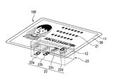
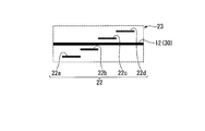
- the check data 22 having four numbers “9”, “8”, “7”, and “6” as information segments is displayed in the space 23 indicating the check data 22. Therefore, in the second area 12, a hologram structure having four information segments 9, 8, 7, and 6 as reproduced images is formed.
- the hologram structure has a hologram segment that reproduces each of the four information segments.
- the positions (hereinafter, referred to as “reproduction positions”) of the reproduction images 22a, 22b, 22c, and 22d of the information segments in the thickness direction of the authentication body 100 are mutually different. Can be configured differently.
- the reproduced images 22a and 22b can be reproduced below the laminate sheet 30 where the second area 12 is located, and the reproduced images 22c and 22d can be reproduced above the laminate sheet 30.
- the reproduction position of each information segment may constitute a part of the check data 22.
- codes 1, 2, 3, and 4 are assigned to the reproduction positions of the reproduced images 22a, 22b, 22c, and 22d, respectively, the check data 22 indicated by the reproduced images shown in FIG. 2A and FIG. , “98761234” and “91827364”. That is, the check data 22 indicated by the reproduced image can be a sequence of numbers, a character string, or a sequence of a combination of numbers and characters.
- the configuration itself of each part of the authentication body 100 can be a known one. Therefore, a known method can be applied to the production.
- the authenticator 100 is characterized by the included individual information. Therefore, the following mainly describes the procedure for the individual information.
- the authentication body 100 including the individual information can be a license card, an ID card, or the like. That is, the personal identification information formed on each of the authentication bodies 100 may be different.
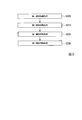
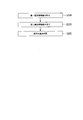
- FIG. 3 is a flowchart of a procedure for forming individual information added to the authentication body 100.
- personal identification information 21 is obtained.
- Step S200 is typically obtained from an application document filled in by the owner to whom the authenticating body 100 is issued or an input form on the web, but is not limited to this.
- check data 22 is generated based on the personal identification information 21 obtained in step S200.
- a hash value is obtained from a part or all of the personal identification information 21 by a hash function and used as check data.
- a simple hash function may be used to generate the check data.
- characters and numbers contained in personal identification information can be converted to ASCII codes to form a number string, and the remainder obtained by dividing by a specific number string can be used as check data .
- specific information for example, a combination of the last two digits of the date of birth and the character of the first name
- the check data may be used as it is.
- the hash function can be a cryptographic hash function.
- As the cryptographic hash function a secure hash algorithm of the National Institute of Standards and Technology can be applied.
- a cryptographic hash function can apply a block cipher. Examples of cryptographic hash functions are MD5, SHA family, Whirlpool, RIPEMD, RadioGatun, bcrypt, BLAKE2.
- step S210 When step S210 is completed, all the individual information to be added to the authentication body 100 is prepared.
- the personal identification information 21 obtained in step S200 and the check data 22 obtained in step S210 are reproducibly associated by the process performed in step S210.
- step S220 personal identification information 21 is formed in first area 11 of laminate sheet 30.
- the laser can be a pulsed laser.
- a pulse laser is easy to adjust power at its transmission frequency.
- the pulse laser can be a solid state laser. Examples of solid-state lasers are YVO4 lasers and YAG lasers.
- the transmission frequency of the pulse laser can be 1 MHz or less from continuous wave (CW).
- the pulse width of the pulsed laser can be from 100 microseconds to 100 femtoseconds.
- the personal identification information 21 can be recorded by carbonizing a part of the laminate sheet 30 with a laser. Alternatively, the personal identification information 21 can be recorded by printing the personal identification information 21 on the laminate sheet 30 with ink and discoloring the ink with a laser.
- the ink can be a fluorescent ink or an infrared absorbing ink.
- the fluorescent ink or the infrared absorbing ink can be a dye ink or a pigment ink. Fluorescent inks and infrared absorbing inks are invisible inks.
- a latent image can be formed with an invisible ink. In other words, the personal identification information 21 of the latent image can be formed by changing the color of a part of the invisible ink. Thereby, forgery resistance can be further improved.
- An example of a visible ink is an optically variable ink.
- the optically variable ink can be a magnetic ink.
- the optically variable ink having magnetism can form a characteristic pattern by a magnetic field. Since it is difficult to imitate a characteristic pattern by a magnetic field, forgery can be prevented.
- a hologram structure using the check data 22 as a reproduced image is formed in the second area 21 of the laminate sheet 30.
- the hologram structure can be formed by selectively transferring information segments matching the check data from a hologram film on which information segments have been recorded in advance.
- the check data is composed of only Arabic numerals
- the information segment of the check data is ten numbers from 0 to 9. Therefore, as shown in FIG. 4A, using a hologram film (hologram structure group) 150 in which a large number of hologram structures each having a 10-digit number as a reproduced image are formed regularly in advance, and only the portion of the number to be used is set in the second area. 21 may be sequentially arranged and fixed.
- the hologram film has a plurality of hologram structures.
- FIG. 4B is a cross-sectional view taken along line II of FIG. 4A.
- the hologram structures of five identical numbers arranged in the same column have different reproduction positions 150a, 150b, 150c, 150d, and 150e, respectively. Therefore, it is possible to cope with any reproduction position set to a numeral in the check data.
- the hologram film 150 ten types of hologram films in which a number of hologram structures each having a different number as a reproduced image are formed may be used.
- 4A and 4B show the hologram film 150 composed of only Arabic numerals, but may be character information. Examples of character information are alphabets and Greek letters.
- a method for selectively transferring a specific information segment to the second area a method using a thermal head or a laser can be applied.
- An adhesive layer is formed on the back surface of the hologram film 150, and only the information segment to be transferred is melted by the heat of the thermal head or the heat of the laser, whereby selective transfer can be performed.
- an adhesive layer that has already exhibited adhesiveness may be provided on the back surface of the hologram film 150, and the adhesive layer in a non-transferred area may be partially removed by laser.
- the method of forming the check data is not limited to the above-described embodiment using the hologram film.
- the hologram structure may be formed by forming the check data generated on the intermediate transfer foil and pasting or laminating the check data on the second area 12.
- a part of the laminate sheet is made transparent, and a pulse laser is used to generate material deterioration corresponding to the optical phase information of the generated check data inside the transparent part, so that the check data 22 is stored inside the laminate sheet 30.
- a hologram structure serving as a reproduced image may be formed.
- FIGS. 4A and 4B show an example in which only an information segment for forming check data is formed on the hologram film 150, but the information segment is attached to the second area 12 or the intermediate transfer foil film.
- a guide pattern used for positioning for attaching may be printed and provided. Note that the guide pattern may also be formed by a hologram structure. Examples of guide patterns are rectangles, crosses, circles, triangles, polygons, and combinations thereof.
- step S200 to S230 the order of steps S200 to S230 described above can be changed without contradiction.
- the following changes are possible.
- -The order of steps S220 and S230 is reversed.
- a part of the second area may overlap with the first area.
- falsification due to replacement can be prevented.
- the hologram structure may be embedded inside the ID card.
- the hologram structure when embedding a hologram structure for reproducing check data in an authentication body, first, the hologram structure is transferred to the laminate sheet 30. Transfer can be performed using a metal or resin stamper.
- the surface temperature of the stamped surface of the stamper is set to 80 ° C. or more and 150 ° C. or less, and the time required for the hologram structure to contact the object to be transferred by the stamper is 0.1 second or more It can be set to 3 seconds or less, and the transfer pressure can be set to 100 kg / cm 2 or more and 500 kg / cm 2 or less.
- a transparent cover layer is laminated on one surface of the laminate sheet 30 on which the hologram structure has been transferred.
- the material of the cover layer can be thermoplastic. Since the thermoplastic is softened by heat, the cover layer is pressed against the laminate sheet 30 and the hologram structure to be integrated by hot pressing. The integration can cover one surface of the laminate sheet and also cover the hologram structure.
- the temperature of the heat source can be set to 170 ° C. or more and 200 ° C. or less, and the time during which the heat source contacts the heat source can be set to 1 minute or more and 30 minutes or less.
- the personal identification information 21 can be read by a known reading device.
- This device can be a line scanner.
- the personal identification information 21 can be read by a known reading device by irradiating light of a predetermined wavelength from a predetermined angle.
- the check data 22 is recorded as a reproduced image of the hologram structure, it is not correctly reproduced unless light of a predetermined wavelength serving as reference light of the hologram structure is irradiated from a predetermined angle.
- the reproduced image is displayed, but the reproduction position is shifted from the correct position.
- the reproduced image is displayed, but the reproduced image is formed at a position deviated from the reading position of the camera or the optical sensor.
- condition information indicating the reading condition of the check data is obtained (step A), and based on this condition information, the second region is irradiated with light of a predetermined wavelength at a predetermined angle. Then, the check data is read (step C).
- condition information is obtained in step A.
- the condition information is acquired in step A in the condition that the condition information is included in the personal identification information 21 and the condition information is acquired when the personal identification information 21 is read, or the condition information is read in advance by the provider of the authenticating body and provided to the user. And the like.
- the provider of the certified body manufactures the certified body while periodically changing the condition information, and reads the production time of the certified body (generally synonymous with the time of delivery to the owner) and the condition information in association with each other. It may be provided to the user.
- the changed condition information is reflected in a part of the personal identification information in real time, so that it is not necessary to provide the reading user with the information.
- the condition information may be processed and included in the personal identification information.
- the processing may be encryption.
- FIG. 5 is a flowchart showing the flow of the authentication body verification method according to the present embodiment.
- step S310 the personal identification information 21 in the first area 11 is read.
- step S320 the check data 22 in the second area 12 is read. Steps S310 and S320 may be executed by the above-described method for reading an authenticating body.
- step S330 it is determined whether or not the check data 22 obtained in step S320 satisfies the correspondence with the personal identification information 21 obtained in step S310, thereby determining whether the authenticator 100 is authentic. Is done. Some examples of step S330 are shown below.
- the personal identification information and the check data are collated to verify whether they match. When a part of the personal identification information is used as the check data as it is, the check data can be collated and verified with a part of the personal identification information as the check data.
- the personal identification information 21 and the check data 22 are verified from the stored database.
- the database may be in the reader of the authenticating body, or may be in a server or cloud on the Internet. c.
- the personal identification information 21 acquired in step S310 is converted by a conversion method for generating check data to generate check data for verification, and the generated check data for verification and the check data 22 obtained in step S320 are converted. Collate. d.
- the check data 22 obtained in step S320 is converted in the reverse procedure of the conversion method for generating the second individual information to generate collation personal identification information, and the generated collation personal identification information is obtained in step S310. It is compared with the personal identification information 21 thus obtained.
- This mode can be applied to a case where check data is generated in a mode that allows reverse conversion.
- the above c and d have the advantage that there is no need to construct a database for collation and the database does not become huge.
- step S310 and step S320 may be reversed.
- a reading device (reader) applied to the present embodiment can be a reading device including a device for reading personal identification information and a configuration such as a camera and an optical sensor for reading check data.
- the device that reads personal identification information can be a line scanner.
- the authenticator 100 of the present embodiment since the authenticator 100 of the present embodiment includes the personal identification information 21 and the check data 22 associated with the personal identification information 21, it is difficult to forge. That is, when the forger has altered only the personal identification information 21, the forged personal identification information and the check data 22 are not associated with each other. Can be determined. Further, if the user does not know how the check data is generated, the check data corresponding to the rewritten personal identification information cannot be specified, so that the forgery of the check data is substantially impossible. Therefore, the security resistance of the authentication body 100 is higher than a configuration in which a hologram transfer foil recording a shape or pattern not associated with personal identification information is provided.
- the diversity of the check data can be ensured even with a small number of information segments.
- the check data is composed of three numbers, the number of combinations is 1000.
- the number of combinations is 100 times or more, that is, 125,000.
- the difference between the respective reproduction positions is set to a small value (for example, 1 mm or less) that cannot be easily discriminated only by viewing the reproduced image, it becomes difficult for a forger to notice that a plurality of types of reproduction positions are set in the first place. Forgery of the check data can be made more difficult.
- the check data that changes according to the personal identification information is recorded in the hologram structure of the second area 12, and the authenticator 100 having different check data 22 is manufactured in large quantities. it can.
- the check data can be reliably read based on the condition information acquired in step A.
- the authentication body reading method according to the present embodiment makes it possible to simultaneously obtain the personal identification information and the condition information by using the authentication body that includes the condition information in the personal identification information, which is convenient for the reading user. The performance is improved.
- the forged authenticated body is easily and reliably detected. can do.
- the computer generated hologram is used to calculate the hologram structure so that the uppercase letters “A”, “B”, and “C” are reproduced at positions 5 mm, 7 mm, and 9 mm closer to the hologram film interface, respectively.
- a hologram transfer foil having an embossed structure was prepared.
- the reference light was green light.
- the produced hologram transfer foil was transferred to the upper surface of a polycarbonate sheet.
- Another polycarbonate sheet was stacked thereon and subjected to thermal lamination to produce a laminate sheet having a hologram structure embedded therein.
- a reading device equipped with a full-color LED light source, an optical prism, and a CMOS sensor was prepared.
- the authentication body is set in this reading device, light emitted from the light source is perpendicularly incident on the authentication body, and a reproduced image of the hologram structure is formed on the CMOS sensor.
- the installation position (imaging condition) of the CMOS sensor By changing the installation position (imaging condition) of the CMOS sensor, only the reproduced image at each reproduction position can be selectively obtained.
- the check data in the experimental example is “B”. That is, “A” and “C” are dummy reproduced images that do not constitute check data. If the reading conditions (the wavelength of the emitted light and the installation position of the CMOS sensor) of the reading device are in accordance with the conditions, the reading device acquires only the correct check data “B”. If the reading condition is different from the condition information, the reading device cannot acquire correct check data. For example, if the reading condition is “red light, 7 mm before”, the reading device acquires only “C”. If the reading condition is “green light, 3 mm before”, the reading device cannot acquire a reproduced image.
- the reading conditions the wavelength of the emitted light and the installation position of the CMOS sensor
- each authenticator according to the present invention has high resistance to forgery and tampering, and as long as accurate condition information is known, a reader can easily acquire check data and perform verification. Can be.
- condition is “green light, 7 mm before and 9 mm before”
- the check data is “B, C”.
- the condition is “green light, 7 mm in front, and red light, 3 mm in front”
- the check data is “A, B”.
- the condition may include the information of the reference light, the reproduction position, or both.
- a reproduced image may be reproduced at a reproduction position where the information segments of the check data have the same height.
- the personal identification information and the check data may be formed on different surfaces of the laminate sheet.
- the personal identification information may be recorded on the front surface of the laminate sheet, and the check data may be formed on the back surface of the laminate sheet. In this way, if there is a vandalism associated with forgery or counterfeiting of the authenticator, one of the personal identification information and the check data is always affected. Therefore, verification of the authentication body can be easily performed.
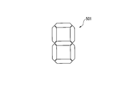
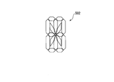
- the hologram structure described above has a shape 501 (7-segment display) for displaying a symbol in seven segments as shown in FIG. 6 and a shape 502 (16-segment display) for displaying a symbol in 16 segments as shown in FIG. ). That is, the hologram structure can be a combination of a plurality of holographic segments. In this case, by removing (demetallizing) the reflection layer in the hologram structure area corresponding to each holographic segment in accordance with the numbers and characters to be displayed, the reproduced images of the hologram structure can be easily recorded in numbers and characters. , Symbol information.
- the number of holographic segments is not limited to the above, and may be in the form of a 14-segment display.
- each segment serving as a constituent unit is a polygon, but may be a shape with rounded corners.
- there is a gap between the segments but the gap may not be present.
- the dimensions of all the gaps may be the same or different. For example, at a portion where two segments are adjacent to each other, the apparent brightness of the reproduced image is dark. Therefore, the distance is short, and at a portion where three segments are adjacent to each other, the apparent brightness of the reproduced image is bright. Therefore, the reproduced image can be optimized by increasing the distance. If there is no gap between the segments, the reflection layer in the adjacent unit cell region may be slightly removed by demetallization, but there is almost no effect on the reproduction image observation.
- Each of the segments in FIGS. 6 and 7 may be composed of a plurality of dot-shaped segments. There are no restrictions on the number or shape of the segments as long as the numbers, characters, and symbols recorded in the hologram structure can be visually recognized as a reproduced image. Also, the code can be recorded by partially removing the reflection layer of the hologram structure.
- the hologram structure may be a holographic segment. With each holographic segment being 1 bit, 0 and 1 data can be recorded depending on the presence or absence of the reflective layer. That is, the holographic segment having the reflective layer can be set to 1, and the holographic segment from which the reflective layer has been removed can be set to 0.
- the holographic segment having the reflective layer can be set to 1, and the holographic segment from which the reflective layer has been removed can be set to 0.
- the code may be recorded depending on the presence or absence of the reflective layer without interlocking with the hologram structure. In this case, when the reflection layer of the hologram structure is removed by the laser, the positional relationship between the position to be removed and the hologram structure may be rough.
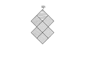
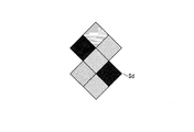
- FIGS. 8 and 9 show examples of the arrangement of the hologram structure in the case where the reproduced image of the hologram structure has seven segments.
- a plurality of unit cell regions arranged in a two-dimensional matrix form one segment.
- the segment 511 shown in FIG. 8 is composed of seven unit cell regions 520.
- the outer shape of the entire hologram structure can be made square as shown in FIG.
- the size of the unit cell region 520 can be 20 ⁇ m or more and 300 ⁇ m or less on one side.
- the size of the unit cell area 520 can be a square circumscribing the unit cell area 521. This makes it difficult to visually observe the unit cell region.
- FIG. 9 is an example in which each segment is constituted by one unit cell region 521.
- the unit cell area in FIG. 9 is larger than the unit cell area in FIG. In this example, alignment during demetallization is simplified.
- the size of the unit cell region 521 can be, for example, 100 ⁇ m or more and 300 ⁇ m or less.
- the size of the unit cell area 521 may be a square circumscribing the unit cell area 521.
- the unit cell area may have a size that can be visually confirmed.
- FIG. 10 shows another example of the arrangement of the unit cell regions 522 in the hologram structure 503 corresponding to the shape of a 16-segment display.
- the plurality of holographic segments may be arranged with a gap.
- a plurality of holographic segments are arranged without gaps, there may be a region where minute hologram structures constituting each holographic segment are mixed, and the boundary between the holographic segments may be ambiguous.
- the removal area may be a linear pattern, a character, a number, a fine pattern, or a geometric pattern.
- authenticity can be verified by checking whether or not the removal area has a predetermined pattern by magnifying observation.
- the reproduction position of the reproduction image Im may be different (see the lower cross-sectional view).
- the reproduction position can be added as information in addition to the numbers and characters formed on demand. As a result, more information can be provided on demand.
- the reproduction position of each reproduced image may change regularly.
- the playback position of each playback image may change monotonously.
- the monotonous change in the reproduction position can be determined by whether the reproduction position monotonously moves away from or approaches the hologram structure. Due to the monotonous change of the reproduction position, it is easy to detect the change of the position of the hologram structure. In the example of FIG. 13, the reproduction position gradually becomes shallower from left to right.
- the playback position may randomly change non-monotonically.
- the non-monotonic change in the playback position can be a regular change or a random change.
- the reproduction position may be different for each segment.
- Laser ablation is one of the methods of demetallization.
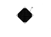
- the focused diameter of the laser and the distance G between the outer edge of the region R1 where the calculated hologram structure is formed in the unit cell region and the outer edge P1 of each unit cell region. contributes to the positioning accuracy at the time of ablation.
- the removal area is circular. Therefore, when the distance G is small, as shown in FIG. 15, the reflection layer in the region R1 cannot be completely removed, and the reflection layers remain at the four corners. From the viewpoint of preventing this, the distance G can be equal to or larger than the focused diameter of the laser. Further, the diameter may be twice or more the diameter of the condensed light. Further, the distance G may be equal to or less than 100 times the focused diameter of the laser.
- An alignment mark may be provided in order to increase the alignment accuracy of laser ablation.
- the alignment mark can be formed by hologram, diffraction grating pattern, or printing.
- the line width of the reflective layer to be removed by laser ablation can be in the range of 1 ⁇ m or more and 100 ⁇ m or less.
- the resolution of the hologram structure for displaying information can be increased.
- the thickness is 100 ⁇ m or less, it can be easily processed with a laser.
- the density of the reproduction light source for reproducing each segment may be uniform over the entire segment or may be different for each part. Increasing the density of the reproduction light source at the center of the segment and lowering the density of the reproduction light source at the periphery of the segment blurs the boundaries between adjacent segments and suppresses the deterioration of the reproduced image quality due to the demetalization of the reflective layer. Can be. Conversely, if the density of the reproduction light source is reduced at the center of the segment and the density of the reproduction light source is increased at the periphery of the segment, the visibility of the segment can be increased.
- the density change of the reproduction light source may be continuous or intermittent.
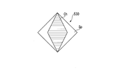
- the area where the hologram structure is provided in the unit cell area can be set according to the reproduced image.
- the reproduced image becomes brightest.
- the reproduction position of the reproduced image particularly the position in the thickness direction of the authentication body, there is a possibility that a part of the segment may appear to be missing when the authentication body is observed from a certain angle.
- a blank region without a hologram structure is formed on both sides in the left-right direction in the unit cell region 530, or a blank region Sp is formed on both sides in the vertical direction in the unit cell region 530, as shown in FIG.
- the blank region Sp may be formed by demetallization of the reflective layer.
- the reflective layer can be formed of a metal material, a metal oxide, a metal sulfide, or a combination thereof. When formed from these materials, the reflectance from the hologram structure can be increased, and the reproduced image also becomes bright.
- a metal oxide or a metal sulfide having a light transmitting property can be used in a field where a transparent authenticator such as a personal authentication card is required.
- a transparent authenticator such as a personal authentication card is required.
- laser ablation can be performed by disposing a specific wavelength absorbing ink or the like near the reflective layer.
- a solid laser can be used as a laser for laser ablation.
- the solid-state laser are a YVO4 laser (oscillation wavelength of 1064 nm) and a YAG laser (oscillation wavelength of 1064 nm).
- an infrared absorbing ink as the specific wavelength absorbing ink may be arranged near the reflective layer. This makes it easier to increase the speed of laser scanning.
- the fine uneven structure of the hologram film having the fine uneven structure may be partially covered with the reflective layer of the metal material.
- the reflective layer may be patterned linearly.
- the linear pattern may be a mesh.
- the reproduction position of the reproduction image may be changed other than the above-described depth.
- the reproduced image Im is reproduced not at the normal direction to the hologram structure 540 but at a position away from the normal line N in the direction forming an angle ⁇ .
- the reproduced image Im is shifted upward (positive y-axis direction in FIG. 19) with respect to the hologram structure 540.
- the shift direction is not limited to the upward direction, and can be set downward, in the left-right direction (x-axis direction in FIG. 19), or in an oblique direction.
- the shift amount can also be set. In the example shown in FIG.
- the reproduced image and the hologram structure are non-parallel. That is, the distance D1 between the reproduced image Im and the hologram structure 540 at the lower end of the reproduced image Im is smaller than the distance D2 between the reproduced image Im and the hologram structure 540 at the upper end of the reproduced image Im.
- the distance between Im and the hologram structure 540 gradually increases.
- Physical entity can refer to a physical form or a spatial form surrounded by a substance.
- Physical entities can be structures.
- the structure can have a specific function.
- a combination of structures having a specific function can exhibit a synergistic effect by a combination of each function of each structure.
- Introductory phrases “one or more” or “at least one” and indefinite articles such as “a” or “an” are taken to mean at least “at least” It should be. "One” or “one or more”). The same is true for the use of Articulations used to guide the claims.
- the present invention can be applied to an authentication body.
Landscapes
- Engineering & Computer Science (AREA)
- Physics & Mathematics (AREA)
- General Physics & Mathematics (AREA)
- Manufacturing & Machinery (AREA)
- Theoretical Computer Science (AREA)
- Computer Security & Cryptography (AREA)
- Health & Medical Sciences (AREA)
- General Health & Medical Sciences (AREA)
- Toxicology (AREA)
- Holo Graphy (AREA)
- Credit Cards Or The Like (AREA)
Abstract
認証体は、シート状のラミネートシートと、ラミネートシートに形成され、個人識別情報が記録された第一領域と、ラミネートシートに形成され、第一個別情報と関連付けられたチェックデータが記録されたホログラム構造を有する第二領域とを備える。
Description
本発明の実施形態は、認証体、認証体の製造方法、認証体の読み取り方法、および認証体の検証方法に関する。本願は、2018年6月29日に出願された日本国特願2018-124211および2018年10月30日に出願された日本国特願2018-204306に対し優先権を主張し、その内容を援用する。
個人情報を含む認証体として、パスポートや運転免許証などの各種ID(IDentification)カードが知られている。IDカードには、目視による個人情報の識別を行うために、顔画像や文字情報が表示されているものが多い。個人情報が単純に認証体上に印刷されているだけであると、容易に改ざんや偽造ができてしまう。
認証体の偽造防止方法として、特許文献1には、ホログラム転写箔を認証体に付与することで、認証体の改ざん防止性を向上させることが記載されている。
特許文献2には、蛍光発光材料を用いて、可視光観察では透明で視認できないが、紫外光観察では視認できるように個人情報を付与することが記載されている。
特許文献2には、蛍光発光材料を用いて、可視光観察では透明で視認できないが、紫外光観察では視認できるように個人情報を付与することが記載されている。
特許文献1に記載の偽造防止技術は、既に広く知られていることに加え、単純な虹色の回折光を射出するホログラムであれば、容易に偽造されてしまう。
特許文献3には、さらなる偽造防止方法として、特定波長の光をホログラムに照射することでホログラム上に表示される再生情報を用いて真正の検証を行うことが記載されている。
特許文献3には、さらなる偽造防止方法として、特定波長の光をホログラムに照射することでホログラム上に表示される再生情報を用いて真正の検証を行うことが記載されている。
特許文献3の記載の技術では、再生情報は予め設計されており不変である。そのため、偽造者が再生情報を知ってしまうと、再生情報を模倣したホログラムが作製されてしまう可能性があり、いまだ改善の余地がある。
上記事情を踏まえ、本発明の実施形態は、簡潔な構成で改ざんや偽造を抑止できる認証体および検証に関する技術を提供することを目的とする。
本発明の実施形態は、背景からの独自の単一の発明を元とする一群の実施形態である。また、本開示の各側面は、単一の発明を元とした一群の実施形態の側面である。本開示の各構成は、本開示の各側面を有しうる。本発明の解決手段として、本発明の実施形態は、下記の側面を有する。各側面は、組合せることができ、組合せはシナジーを実現できる。また、各側面は、実施形態のフィーチャとも組合せることができ、組合せはシナジーを実現できる。また、実施形態の各フィーチャは組合せることができ、組合せはシナジーを実現できる。
本発明の第一の側面は、シート状のラミネートシートと、ラミネートシートに形成され、第一個別情報が記録された第一領域と、ラミネートシートに形成され、第一個別情報と関連付けられた第二個別情報が記録されたホログラム構造を有する第二領域とを備える認証体である。
本発明の第一の側面は、シート状のラミネートシートと、ラミネートシートに形成され、第一個別情報が記録された第一領域と、ラミネートシートに形成され、第一個別情報と関連付けられた第二個別情報が記録されたホログラム構造を有する第二領域とを備える認証体である。
本発明の第二の側面は、第一個別情報を取得する工程と、第一個別情報に基づいて、第一個別情報と関連付けられた第二個別情報を生成する工程と、第一個別情報をラミネートシートに記録する工程と、第二個別情報を記録したホログラム構造をラミネートシートに形成する工程とを備える認証体の製造方法である。
本発明の第三の側面は、本発明の認証体を読み取る認証体の読み取り方法である。
この方法は、認証体のホログラム構造に第二個別情報が再生されるための条件を示す条件情報を取得する工程と、条件情報に基づいてホログラム構造に光を照射することにより、第二個別情報を再生させる工程とを備える。
この方法は、認証体のホログラム構造に第二個別情報が再生されるための条件を示す条件情報を取得する工程と、条件情報に基づいてホログラム構造に光を照射することにより、第二個別情報を再生させる工程とを備える。
本発明の第四の側面は、本発明の認証体の真偽を判定する認証体の検証方法である。
この方法は、認証体に記録された第一個別情報を読み取る工程と、認証体のホログラム構造に記録された第二個別情報を読み取る工程と、読み取られた第一個別情報および第二個別情報に基づいて、認証体の真偽を判定する工程とを備える。
この方法は、認証体に記録された第一個別情報を読み取る工程と、認証体のホログラム構造に記録された第二個別情報を読み取る工程と、読み取られた第一個別情報および第二個別情報に基づいて、認証体の真偽を判定する工程とを備える。
本発明の実施形態によれば、簡潔な構成で改ざんや偽造を抑止できる。
以下、本発明の一実施形態について、図1から図20を参照しながら説明する。
(認証体)
図1は、本実施形態における認証体100の平面図である。認証体1は、シート状のラミネートシート30と、ラミネートシート30の一部に形成された第一領域11および第二領域12とを備えている。
認証体は、積層体とできる。積層体は、カードまたはページとできる。積層体は、複数のラミネートシート30をラミネートしたものとできる。ラミネートシート30は、熱可塑性のプラスチックシートとできる。ラミネートシート30の材質は、ポリカーボネートまたは塩化ビニルとできる。積層体としては、ポリカーボネートのシート状積層体や、塩化ビニルのシート状積層体とできる。積層は、熱ラミネートが適用できる。カードは、IDカード、国民IDカード、クレジットカード、運転免許証カード、外国人登録カード(Alien registration card)等とできる。ページは、パスポートのデータページとできる。ページの厚みは、0.5mm以上、2.5mm以下とできる。
図1は、本実施形態における認証体100の平面図である。認証体1は、シート状のラミネートシート30と、ラミネートシート30の一部に形成された第一領域11および第二領域12とを備えている。
認証体は、積層体とできる。積層体は、カードまたはページとできる。積層体は、複数のラミネートシート30をラミネートしたものとできる。ラミネートシート30は、熱可塑性のプラスチックシートとできる。ラミネートシート30の材質は、ポリカーボネートまたは塩化ビニルとできる。積層体としては、ポリカーボネートのシート状積層体や、塩化ビニルのシート状積層体とできる。積層は、熱ラミネートが適用できる。カードは、IDカード、国民IDカード、クレジットカード、運転免許証カード、外国人登録カード(Alien registration card)等とできる。ページは、パスポートのデータページとできる。ページの厚みは、0.5mm以上、2.5mm以下とできる。
第一領域11には、認証体100の個人識別情報21が記録されている。個人識別情報21は、所有者の個人識別情報とできる。個人識別情報には、カード、冊子の所有者の情報を含むことができる。個人識別情報は、個人の生体情報、個人の非生体情報、またはその対である。生体情報は個人を識別可能な生体情報とできる。生体情報により、生体認証することができる。非生体情報の実例は、名前、生年月日、出身国、出身地、個人識別番号である。また、これらは文字、数字、記号などの組合せとできる。個人の生体情報の実例は、顔画像、指紋パターン、網膜パターン、声紋、筆跡、サインである。個人識別情報21は、目視での本人確認ができるように、可視光下で視認できる構成で設けられている。
ラミネートシート30の材質は、熱可塑プラスチックとできる。ラミネートシート30の熱可塑プラスチックは、ポリカーボネート樹脂とできる。ポリカーボネート樹脂は、レーザーエングレービングで個人識別情報21を記録することができる。レーザーをラミネートシート30に照射し、レーザーの熱でポリカーボネート樹脂が炭化することで、個人識別情報21をレーザー印字できる。記録する個人識別情報21に応じて、描画位置、描画深さ、描画ポイント、パルス幅、パスル周波数、パルスエネルギー、レーザー照射強度またはレーザー照射時間、その組合せを変調することで、個人識別情報21を記録できる。
個人識別情報21の記録は、レーザーエングレービングに限られない。レーザーエングレービングに替えて、ラミネートシート30上に印刷することで個人識別情報21を形成してもよい。あるいは、ラミネートシート30とは異なる樹脂シートに個人識別情報21を印刷し、ラミネートシート30に貼り合わせたり、透明なラミネートシートの内部に埋め込み配置したりしてもよい。
ラミネートシート30の表面や内部に個人識別情報21を付与すると、認証体100が偽造や模造のために破壊された場合に個人識別情報21も同時に破壊されるため、偽装行為や模造行為があったことを検知できる。
ラミネートシート30の表面や内部に個人識別情報21を付与すると、認証体100が偽造や模造のために破壊された場合に個人識別情報21も同時に破壊されるため、偽装行為や模造行為があったことを検知できる。
第二領域12には、ホログラム構造が形成されている。ホログラム構造は、図2Aに示すように、個人識別情報12から生成されたチェックデータ22を再生像として表示する。ホログラム構造には、チェックデータ22が記録されている。
チェックデータ22が記録されたホログラム構造は、個人の生体情報が記録されている領域に重ねて形成してもよい。つまり、個人の生体情報が記録された領域の一領域または全領域に、ホログラム構造も形成されてもよい。この場合、生体情報が改ざんされる際にホログラム構造も破壊されるため、ホログラム構造を流用する改ざんを防止できる。このとき、チェックデータ22は、個人の非生体情報から生成されてもよい。これにより、個人の国籍等の非生体情報と顔画像等の生体情報をすりかえる成りすましを防止しやすい。
チェックデータ22は、個人の非生体情報のみから生成されてもよい。これにより、チェックデータ22をより容易に生成できる。
チェックデータ22が記録されたホログラム構造は、個人の生体情報が記録されている領域に重ねて形成してもよい。つまり、個人の生体情報が記録された領域の一領域または全領域に、ホログラム構造も形成されてもよい。この場合、生体情報が改ざんされる際にホログラム構造も破壊されるため、ホログラム構造を流用する改ざんを防止できる。このとき、チェックデータ22は、個人の非生体情報から生成されてもよい。これにより、個人の国籍等の非生体情報と顔画像等の生体情報をすりかえる成りすましを防止しやすい。
チェックデータ22は、個人の非生体情報のみから生成されてもよい。これにより、チェックデータ22をより容易に生成できる。
チェックデータ22は、個人識別情報12から生成(provide)される。チェックデータ22は、個人識別情報12の特定の一部をデータとして抜き出したり、個人識別情報12の一部または全部から、定められたアルゴリズムでデータを生成したりすることで生成できる。個人の生体情報の一部または全部から、ハッシュ関数によりハッシュ値を得てチェックデータ22としてもよい。また、個人の生体情報のみの一部または全部から、ハッシュ関数によりハッシュ値を得てチェックデータとしてもよい。これにより、生体情報の改ざんを、チェックデータ22により検出できる。このとき、チェックデータ22が記録されたホログラム構造は、個人の非生体情報が記録されている領域に重ねて形成してもよい。つまり、個人の生体情報が記録された領域の一領域または全領域に、ホログラム構造も形成されてもよい。これにより、個人の国籍等の非生体情報と顔画像等の生体情報とをすりかえる成りすましを防止しやすい。
チェックデータ22は、デジタルデータとできる。デジタルデータは、個人識別情報12の一部と同一の数字、アルファベット、各種言語における文字の単数または複数のセットでもよい。あるいは、個人識別情報12の全部または一部の数字、文字を関数、行列やアルゴリズムで変換して得られた数字、文字、記号であってもよい。デジタルデータは、コードとしてホログラム構造に記録してもよい。コードは1次元コードあるいは2次元コードとできる。1次元コードの実例は、バーコードである。2次元コードの実例は、QRコード(登録商標)やマトリックスコードである。
チェックデータ22は、個人識別情報21の一部または全部のハッシュ値とできる。チェックデータの生成に用いられるシンプルなハッシュ関数は、個人識別情報に含まれる文字、数字をアスキーコードに変換させて数字列とし、特定の数字列で割ることで得た余りをチェックデータとできる。あるいは、個人識別情報に含まれる特定の情報(例えば生年月日の下2桁とファーストネームの文字の組合せなど)を、そのままチェックデータとしてもよい。この際、文字や数字の大きさが10μm以上300μm未満の範囲とできる。この範囲であれば、肉眼にて視認できないチェックデータとできる。このような文字は、マイクロテキストとできる。文字や数字のサイズを300μm以上5mm以下の範囲とすることもできる。この範囲であれば、肉眼で視認可能なチェックデータとできる。
ハッシュ値を生成するハッシュ関数は、暗号学的ハッシュ関数とできる。暗号学的ハッシュ関数としては、アメリカ国立標準技術研究所のセキュアハッシュアルゴリズムやブロック暗号を適用できる。暗号学的ハッシュ関数の実例は、MD5、SHAファミリ、Whirlpool、RIPEMD、RadioGatun、bcrypt、BLAKE2である。
チェックデータ22の情報量は、個人識別情報12の情報量より少ない。チェックデータ22のビット数は、固定長または可変長とできる。チェックデータ22のビット数は、1ビット以上、1024ビット以下とでき、2ビット以上、64ビット以下の範囲としてもよい。この範囲であれば、チェックデータ22をより扱いやすくできる。チェックデータ22のビット数を可変長とした場合、チェックデータ22のビット数は、認証体が要求されるセキュリティレベルに応じた値とできる。ホログラム構造自体にセキュリティ性があるため、チェックデータは、1ビットまたは2ビットでも十分な場合もある。また、初期の発行数の少ないときは、ビット数を少なく、発行数が増えた場合に順次ビット数を増やしてもよい。こうすることで、例えば外国人登録カードとして認証体を適用する場合に、登録する外国人数に応じてセキュリティ性を順次高めることができる。すなわち、スケーラブルなセキュリティ性を実現できる。
チェックデータ22は、デジタルデータとできる。デジタルデータは、個人識別情報12の一部と同一の数字、アルファベット、各種言語における文字の単数または複数のセットでもよい。あるいは、個人識別情報12の全部または一部の数字、文字を関数、行列やアルゴリズムで変換して得られた数字、文字、記号であってもよい。デジタルデータは、コードとしてホログラム構造に記録してもよい。コードは1次元コードあるいは2次元コードとできる。1次元コードの実例は、バーコードである。2次元コードの実例は、QRコード(登録商標)やマトリックスコードである。
チェックデータ22は、個人識別情報21の一部または全部のハッシュ値とできる。チェックデータの生成に用いられるシンプルなハッシュ関数は、個人識別情報に含まれる文字、数字をアスキーコードに変換させて数字列とし、特定の数字列で割ることで得た余りをチェックデータとできる。あるいは、個人識別情報に含まれる特定の情報(例えば生年月日の下2桁とファーストネームの文字の組合せなど)を、そのままチェックデータとしてもよい。この際、文字や数字の大きさが10μm以上300μm未満の範囲とできる。この範囲であれば、肉眼にて視認できないチェックデータとできる。このような文字は、マイクロテキストとできる。文字や数字のサイズを300μm以上5mm以下の範囲とすることもできる。この範囲であれば、肉眼で視認可能なチェックデータとできる。
ハッシュ値を生成するハッシュ関数は、暗号学的ハッシュ関数とできる。暗号学的ハッシュ関数としては、アメリカ国立標準技術研究所のセキュアハッシュアルゴリズムやブロック暗号を適用できる。暗号学的ハッシュ関数の実例は、MD5、SHAファミリ、Whirlpool、RIPEMD、RadioGatun、bcrypt、BLAKE2である。
チェックデータ22の情報量は、個人識別情報12の情報量より少ない。チェックデータ22のビット数は、固定長または可変長とできる。チェックデータ22のビット数は、1ビット以上、1024ビット以下とでき、2ビット以上、64ビット以下の範囲としてもよい。この範囲であれば、チェックデータ22をより扱いやすくできる。チェックデータ22のビット数を可変長とした場合、チェックデータ22のビット数は、認証体が要求されるセキュリティレベルに応じた値とできる。ホログラム構造自体にセキュリティ性があるため、チェックデータは、1ビットまたは2ビットでも十分な場合もある。また、初期の発行数の少ないときは、ビット数を少なく、発行数が増えた場合に順次ビット数を増やしてもよい。こうすることで、例えば外国人登録カードとして認証体を適用する場合に、登録する外国人数に応じてセキュリティ性を順次高めることができる。すなわち、スケーラブルなセキュリティ性を実現できる。
第二領域12のホログラム構造には、各種の公知構造を適用できる。中でも形成層中の屈折率を変調した体積ホログラムや表面にレリーフ構造を有する表面レリーフホログラムがホログラム構造に適している。体積ホログラムは、リップマンホログラムとできる。表面レリーフホログラムは、計算機ホログラムとできる。計算機ホログラムはキノフォームとできる。計算機ホログラムとは、再生像から回折格子ホログラムパターンを計算して形成するホログラムである。キノフォームは、キノフォームに記録する再生像のキノフォーム上での位相をキノフォームの面上に位相差として記録したものである。光学位相情報が記録されたリップマン型ホログラムや計算機ホログラムを、ホログラムフィルムとして形成できる。再生像を表示するための光学位相情報が記録されたホログラムフィルムの一部をカードやページの定位置に転写することができる。これにより、チェックデータ22の再生像を精密な位置に再生できる。
第二領域12のホログラム構造をリップマン型の体積ホログラムとした場合は、光応答性のフォトポリマーに対し、設定したチェックデータからの物体光と、その物体光を再生するための参照光とを照射し、その干渉縞をフォトポリマーに記録させることで形成できる。あるいは、チェックデータからの物体光の光学位相情報を予め計算機にて計算し、その光学位相情報を空間光位相変調器の位相差の空間分布とし、その空間光位相変調器を透過あるいは反射した光を物体光としてリップマン型の体積ホログラムを形成してもよい。体積ホログラムの材料は、感光して屈折率が変調するフォトポリマーとできる。フォトポリマーの種類は、光架橋型、または、光重合型とできる。光架橋型の実例は、ポリビニルカルバゾールを主成分したものである。光重合型は、感光時の連鎖反応により高感度としやすい。光架橋型は、屈折率差を大きくしやすい。光重合型の種類は、現像処理を要する湿式、または、現像処理不要の乾式とできる。乾式のフォトポリマーは、屈折率の異なる相溶性の低い材料のペアを主成分とできる。主成分のペアの実例は、酢酸ビニル化合物とアクリル酸エステル化合物、または、エポキシ化合物とアクリル酸エステル化合物であり、これらの片方がポリマーであってもよい。酢酸ビニル化合物およびアクリル酸エステル化合物を主成分のペアとしたフォトポリマーは、屈折率差をつけやすい。エポキシ化合物およびアクリル酸エステル化合物を主成分のペアとしたフォトポリマーは、耐久性を高めやすい。また、湿式の実例は、ポリビニルピロリドンとモノマーとの混合物である。この混合物は、光強度の弱い部分が現像液に溶けてボイドとなるため、屈折率差を大きくしやすい。体積ホログラムは、マスターのホログラムにレーザーを照射し、その反射光(物体光)と照射したレーザーの光(参照光)の干渉縞をフォトポリマーに感光させ、フォトポリマーの屈折率を変調させることで複製できる。(コンタクトコピー法)
表面レリーフホログラムを第二領域12のホログラム構造とする場合は、以下の手順で行える。設定したチェックデータを形成するための光学位相情報を特定する。その光学位相情報を微細凹凸構造の深さとしてレーザー描画装置、あるいは電子線描画装置、イオンビーム描画法でレジスト板に記録する。レジスト板をマスターとして電鋳により、エンボススタンパーを製造する。微細凹凸構造が形成されたこのエンボススタンパーをシリンダーモールドとして、フィルムにエンボスし複製することで、ホログラムフィルムを得られる。エンボスするフィルムは、キャリアとキャリア上に熱可塑性樹脂、硬化樹脂のレリーフ層が形成されてもよい。キャリアは、プラスチックフィルムとできる。プラスチックフィルムは、PETフィルム、PPフィルム、PEフィルムとできる。またキャリアの厚さは、15μm以上、200μm以下とできる。
表面レリーフホログラムは、レリーフ面を有する。レリーフ面は、凹部または凸部、もしくは凹部および凸部を有した表面レリーフを有し、回折、光反射抑制、等方性または異方性の光散乱、屈折、偏光・波長選択性の反射、透過、光反射抑制などの光学的性質を発現する。レリーフ層22に、例えば0.5μm以上2μm以下のピッチ、0.05μm以上0.5μm以下の深さで、回折格子構造の領域を設けることで、ホログラム構造は光を回折させる性質を発現する。レリーフ層に、例えば0.1μm以上0.5μm以下のピッチ、0.25μm以上0.75μm以下の深さで、モスアイ構造や深い格子構造を設けることで表面レリーフホログラムは、光反射抑制の性質や、偏光・波長選択性の反射、透過、光反射抑制を発現する。表面レリーフホログラムに、例えば0.5μm以上3μm以下の平均ピッチ、0.05μm以上0.5μm以下の深さで、非周期的な線状またはドット状の繰り返し構造の領域を設けることで、表面レリーフホログラムは等方的なあるいは異方的な散乱光を射出する性質を発現する。表面レリーフホログラムに、3μmより大きい平均ピッチ、0.5μmより深い構造の領域を設け、隣接する層と異なる屈折率とすることで、表面レリーフホログラムは屈折の性質を発現する。ホログラム構造の光学的性質は、目視や機械検知によって、知覚、検知することができる。これにより偽造改ざん防止性能や美観を向上することができる。
ホログラム構造は、複数のホログラム構造領域を有してもよい。ホログラム構造領域は、単体として、または複数の統合として画像を表示できる。画像は、テキストまたはコードの単体またはそれらの組合せとできる。コードは、一次元コード、二次元コードとできる。一次元コードの実例は、バーコード、シリアルナンバーまたは双方の組合せである。二次元コードの実例は、QRコードやマトリックスコードである。
表面レリーフホログラムは、レリーフ面を有する。レリーフ面は、凹部または凸部、もしくは凹部および凸部を有した表面レリーフを有し、回折、光反射抑制、等方性または異方性の光散乱、屈折、偏光・波長選択性の反射、透過、光反射抑制などの光学的性質を発現する。レリーフ層22に、例えば0.5μm以上2μm以下のピッチ、0.05μm以上0.5μm以下の深さで、回折格子構造の領域を設けることで、ホログラム構造は光を回折させる性質を発現する。レリーフ層に、例えば0.1μm以上0.5μm以下のピッチ、0.25μm以上0.75μm以下の深さで、モスアイ構造や深い格子構造を設けることで表面レリーフホログラムは、光反射抑制の性質や、偏光・波長選択性の反射、透過、光反射抑制を発現する。表面レリーフホログラムに、例えば0.5μm以上3μm以下の平均ピッチ、0.05μm以上0.5μm以下の深さで、非周期的な線状またはドット状の繰り返し構造の領域を設けることで、表面レリーフホログラムは等方的なあるいは異方的な散乱光を射出する性質を発現する。表面レリーフホログラムに、3μmより大きい平均ピッチ、0.5μmより深い構造の領域を設け、隣接する層と異なる屈折率とすることで、表面レリーフホログラムは屈折の性質を発現する。ホログラム構造の光学的性質は、目視や機械検知によって、知覚、検知することができる。これにより偽造改ざん防止性能や美観を向上することができる。
ホログラム構造は、複数のホログラム構造領域を有してもよい。ホログラム構造領域は、単体として、または複数の統合として画像を表示できる。画像は、テキストまたはコードの単体またはそれらの組合せとできる。コードは、一次元コード、二次元コードとできる。一次元コードの実例は、バーコード、シリアルナンバーまたは双方の組合せである。二次元コードの実例は、QRコードやマトリックスコードである。
ホログラムフィルムに形成された微細凹凸構造により生じる回折光の輝度を向上させるため、微細凹凸構造を形成したホログラムフィルムの、微細凹凸構造を反射層でカバーしてもよい。つまり、ホログラム構造は、反射層でカバーされてもよい。反射層は、微細凹凸構造に気相堆積することで、凹凸構造をカバーできる。気相堆積は、化学気相堆積、物理気相堆積とできる。物理気相堆積は、真空蒸着やスパッタが適用できる。反射層の材質は、金属酸化物、金属、酸化ケイ素とできる。金属酸化物は、硫化金属、酸化金属、チッ化金属、フッ化金属とできる。
硫化金属の実例は、硫化亜鉛である。酸化金属の実例は、酸化チタン、酸化アルミニウム、ジルコニアである。チッ化金属の実例は、チッ化チタンである。フッ化金属の実例は、フッ化カルシウム、フッ化マグネシウムである。金属は、アルミ(Al)や金(Au)、銀(Ag)、クロム(Cr)、ニッケル(Ni)とできる。あるいはこれらの合金とできる。反射層は、ホログラム構造の再生像の輝度を向上させる。つまり、反射層により、ホログラム構造が再生像として表示するチェックデータ22の輝度が高まる。そのため、認証体をより判別しやすくなる。判別には、後述する観察方法および検証方法が適用できる。反射層の厚みは、の厚みは、10nm以上、500nm以下の範囲とすることができる。10nm以上であれば、認証体の判別性を高めやすい。500nm以下であれば、堆積しやすい。
硫化金属の実例は、硫化亜鉛である。酸化金属の実例は、酸化チタン、酸化アルミニウム、ジルコニアである。チッ化金属の実例は、チッ化チタンである。フッ化金属の実例は、フッ化カルシウム、フッ化マグネシウムである。金属は、アルミ(Al)や金(Au)、銀(Ag)、クロム(Cr)、ニッケル(Ni)とできる。あるいはこれらの合金とできる。反射層は、ホログラム構造の再生像の輝度を向上させる。つまり、反射層により、ホログラム構造が再生像として表示するチェックデータ22の輝度が高まる。そのため、認証体をより判別しやすくなる。判別には、後述する観察方法および検証方法が適用できる。反射層の厚みは、の厚みは、10nm以上、500nm以下の範囲とすることができる。10nm以上であれば、認証体の判別性を高めやすい。500nm以下であれば、堆積しやすい。
無機材料の反射層は、上述のドライコーティング技術以外に、ゾルゲル法などのウェットコーティングにより形成できる。ホログラム構造は、さらに接着層を有してもよい。接着層の材料は、アクリル、ポリエステル、ウレタンまたは、これらのコンポジット、混合、共重合とできる。接着層は、粉体を含有してもよい。また、粉体は、無機粉体、ポリマー粉体とできる。接着層は複数の種類の粉体を含有してもよい。また、接着層とホログラム構造の間にアンカー層を有してもよい。アンカー層の材料は、アクリル、ウレタンまたは、これらのコンポジット、混合、共重合とできる。接着層は、ホログラム構造の片面または両面に配置できる。
本実施形態の実例では、チェックデータ22を示す空間23に、4つの数字「9」、「8」、「7」、および「6」を情報セグメントとするチェックデータ22が表示される。したがって、第二領域12には、4つの情報セグメント9、8、7、6を再生像とするホログラム構造が形成されている。ホログラム構造は、4つの各情報セグメントを再生するホログラムセグメントを有する。さらに、ホログラム構造は、図2Bに示すように、各情報セグメントの再生像22a、22b、22c、および22dの認証体100の厚さ方向における位置(以下、「再生位置」と称する。)が互いに異なるように構成できる。すなわち、再生像22aおよび22bは、第二領域12が位置するラミネートシート30よりも下方に再生され、再生像22cおよび22dは、ラミネートシート30よりも上方に再生されるようにできる。
各情報セグメントの再生位置は、チェックデータ22の一部を構成してもよい。例えば、各再生像22a、22b、22c、および22dの再生位置にそれぞれ1、2、3、4のコードが付与されている場合、図2Aおよび図2Bに示される再生像が示すチェックデータ22は、「98761234」や、「91827364」のような形で表現できる。つまり、再生像が示すチェックデータ22は、数列、文字列、または、数字と文字を組み合わせた列とできる。
各情報セグメントの再生位置は、チェックデータ22の一部を構成してもよい。例えば、各再生像22a、22b、22c、および22dの再生位置にそれぞれ1、2、3、4のコードが付与されている場合、図2Aおよび図2Bに示される再生像が示すチェックデータ22は、「98761234」や、「91827364」のような形で表現できる。つまり、再生像が示すチェックデータ22は、数列、文字列、または、数字と文字を組み合わせた列とできる。
(認証体の製造方法)
次に、本実施形態の認証体100の製造方法について説明する。認証体100の各部の構成自体は公知のものとできる。そのため、製造には公知の方法を適用できる。認証体100は、含まれる個別情報に特徴がある。そのため、以下では個別情報に関する手順を中心に説明する。
次に、本実施形態の認証体100の製造方法について説明する。認証体100の各部の構成自体は公知のものとできる。そのため、製造には公知の方法を適用できる。認証体100は、含まれる個別情報に特徴がある。そのため、以下では個別情報に関する手順を中心に説明する。
個別情報を含む認証体100は、ライセンスカード、IDカードなどとできる。つまり、認証体100一つ一つに形成される個人識別情報は、異なることがある。
図3は、認証体100に付加する個別情報形成の手順のフローチャートである。
まずステップS200において、個人識別情報21が取得される。ステップS200は、認証体100が交付される所有者が記入した申請書類や、web上の入力フォームから取得される態様が典型的であるが、これには限られない。
まずステップS200において、個人識別情報21が取得される。ステップS200は、認証体100が交付される所有者が記入した申請書類や、web上の入力フォームから取得される態様が典型的であるが、これには限られない。
続くステップS210において、ステップS200で取得された個人識別情報21に基づいて、チェックデータ22が生成される。ステップS210は、個人識別情報21の一部または全部から、ハッシュ関数によりハッシュ値を得てチェックデータとする。
チェックデータの生成には、シンプルなハッシュ関数を用いてもよい。チェックデータの生成に用いられるシンプルなハッシュ関数としては、個人識別情報に含まれる文字、数字をアスキーコードに変換させて数字列とし、特定の数字列で割ることで得た余りをチェックデータとできる。あるいは、個人識別情報に含まれる特定の情報(例えば生年月日の下2桁とファーストネームの文字の組合せなど)を、そのままチェックデータとしてもよい。
ハッシュ関数は、暗号学的ハッシュ関数とできる。暗号学的ハッシュ関数としては、アメリカ国立標準技術研究所のセキュアハッシュアルゴリズムを適用できる。暗号学的ハッシュ関数は、ブロック暗号を適用できる。暗号学的ハッシュ関数の実例は、MD5、SHAファミリ、Whirlpool、RIPEMD、RadioGatun、bcrypt、BLAKE2である。
チェックデータの生成には、シンプルなハッシュ関数を用いてもよい。チェックデータの生成に用いられるシンプルなハッシュ関数としては、個人識別情報に含まれる文字、数字をアスキーコードに変換させて数字列とし、特定の数字列で割ることで得た余りをチェックデータとできる。あるいは、個人識別情報に含まれる特定の情報(例えば生年月日の下2桁とファーストネームの文字の組合せなど)を、そのままチェックデータとしてもよい。
ハッシュ関数は、暗号学的ハッシュ関数とできる。暗号学的ハッシュ関数としては、アメリカ国立標準技術研究所のセキュアハッシュアルゴリズムを適用できる。暗号学的ハッシュ関数は、ブロック暗号を適用できる。暗号学的ハッシュ関数の実例は、MD5、SHAファミリ、Whirlpool、RIPEMD、RadioGatun、bcrypt、BLAKE2である。
ステップS210が終了すると、認証体100に付加するすべての個別情報が揃う。ステップS200で取得された個人識別情報21とステップS210で取得されたチェックデータ22とは、ステップS210で行われた処理により、再現可能に対応付けられている。
続くステップS220において、個人識別情報21がラミネートシート30の第一領域11に形成される。形成方法としては、上述した各種方法を適用できる。レーザーでラミネートシート30の表面に個人識別情報21を形成すると、認証体100の偽造を困難にできる。
レーザーは、パルスレーザーとできる。パルスレーザーはその発信周波数でパワーを調整しやすい。パルスレーザーは、固体レーザーとできる。固体レーザーの実例は、YVO4レーザーやYAGレーザーである。パルスレーザーの発信周波数は、連続波(CW)から1MHz以下とできる。パルスレーザーのパルス幅は、100マイクロ秒から、100フェムト秒とできる。個人識別情報21は、レーザーによりラミネートシート30の一部を炭化することで記録できる。または、ラミネートシート30にインキで個人識別情報21を印刷し、レーザーでインキを変色させることで記録することもできる。インキは、蛍光インキや赤外吸収インキとできる。蛍光インキや赤外吸収インキは、染料インキや顔料インキとできる。蛍光インキや赤外吸収インキは、不可視インキである。不可視インキにより潜像を形成できる。言い換えれば、不可視インキの一部を変色することで、レーザーで潜像の個人識別情報21を形成できる。これによりさらに偽造耐性を向上できる。可視インキの実例は、光学可変インキである。光学可変インキは、磁性を有するインキとできる。磁気を有した光学可変インキは、磁場により特徴的な柄を形成できる。磁場による特徴的な柄を模倣することは困難であるため、偽造を防止できる。
レーザーは、パルスレーザーとできる。パルスレーザーはその発信周波数でパワーを調整しやすい。パルスレーザーは、固体レーザーとできる。固体レーザーの実例は、YVO4レーザーやYAGレーザーである。パルスレーザーの発信周波数は、連続波(CW)から1MHz以下とできる。パルスレーザーのパルス幅は、100マイクロ秒から、100フェムト秒とできる。個人識別情報21は、レーザーによりラミネートシート30の一部を炭化することで記録できる。または、ラミネートシート30にインキで個人識別情報21を印刷し、レーザーでインキを変色させることで記録することもできる。インキは、蛍光インキや赤外吸収インキとできる。蛍光インキや赤外吸収インキは、染料インキや顔料インキとできる。蛍光インキや赤外吸収インキは、不可視インキである。不可視インキにより潜像を形成できる。言い換えれば、不可視インキの一部を変色することで、レーザーで潜像の個人識別情報21を形成できる。これによりさらに偽造耐性を向上できる。可視インキの実例は、光学可変インキである。光学可変インキは、磁性を有するインキとできる。磁気を有した光学可変インキは、磁場により特徴的な柄を形成できる。磁場による特徴的な柄を模倣することは困難であるため、偽造を防止できる。
続くステップS230において、チェックデータ22を再生像とするホログラム構造がラミネートシート30の第二領域21に形成される。ホログラム構造は、あらかじめ情報セグメントが記録されたホログラムフィルムから、チェックデータに合致する情報セグメントを選択的に転写することで形成することができる。
チェックデータがアラビア数字のみで構成される場合、チェックデータの情報セグメントは、0から9までの10個の数字である。したがって、図4Aに示すように、10個の数字を再生像とするホログラム構造が予め規則的に多数形成されたホログラムフィルム(ホログラム構造群)150を用い、使用する数字の部分のみを第二領域21に順次配置固定してもよい。つまり、ホログラムフィルムは、複数のホログラム構造を有する。図4Bは、図4AのI-I線における断面図である。同一列に並んだ5つの同一数字のホログラム構造は、それぞれ異なる再生位置150a、150b、150c、150d、150eを有する。したがって、チェックデータにおいて数字にどの再生位置が設定されても対応できる。
ホログラムフィルム150に代えて、それぞれ異なる1個の数字を再生像とするホログラム構造が多数形成された10種類のホログラムフィルムとしてもよい。
図4Aおよび図4Bではアラビア数字のみで構成されるホログラムフィルム150を示しているが、文字情報であってもよい。文字情報の実例は、アルファベット、ギリシャ文字である。
チェックデータがアラビア数字のみで構成される場合、チェックデータの情報セグメントは、0から9までの10個の数字である。したがって、図4Aに示すように、10個の数字を再生像とするホログラム構造が予め規則的に多数形成されたホログラムフィルム(ホログラム構造群)150を用い、使用する数字の部分のみを第二領域21に順次配置固定してもよい。つまり、ホログラムフィルムは、複数のホログラム構造を有する。図4Bは、図4AのI-I線における断面図である。同一列に並んだ5つの同一数字のホログラム構造は、それぞれ異なる再生位置150a、150b、150c、150d、150eを有する。したがって、チェックデータにおいて数字にどの再生位置が設定されても対応できる。
ホログラムフィルム150に代えて、それぞれ異なる1個の数字を再生像とするホログラム構造が多数形成された10種類のホログラムフィルムとしてもよい。
図4Aおよび図4Bではアラビア数字のみで構成されるホログラムフィルム150を示しているが、文字情報であってもよい。文字情報の実例は、アルファベット、ギリシャ文字である。
特定の情報セグメントを選択的に第二領域に転写する方法としては、サーマルヘッドやレーザーを用いた方法を適用できる。ホログラムフィルム150の裏面に接着層を形成しておき、サーマルヘッドの熱またはレーザーの熱により転写する情報セグメントの部分だけ接着層を融解させることで、選択的な転写を行える。
あるいは、すでに接着性を発現している接着層をホログラムフィルム150の裏面に設け、転写しない領域の接着層をレーザーにより部分的に除去してもよい。
あるいは、すでに接着性を発現している接着層をホログラムフィルム150の裏面に設け、転写しない領域の接着層をレーザーにより部分的に除去してもよい。
チェックデータを形成する方法は、上述したホログラムフィルムを用いた態様に限られない。中間転写箔上に生成したチェックデータを形成し、これを第二領域12に貼り付けたり、積層したりすることによりホログラム構造を形成してもよい。あるいは、ラミネートシートの一部を透明とし、パルスレーザーで、生成されたチェックデータの光学位相情報に対応する材料変質を透明部分の内部に生じさせることで、ラミネートシート30の内部にチェックデータ22を再生像とするホログラム構造を形成してもよい。
また、図4Aおよび図4Bのホログラムフィルム150には、チェックデータを形成するための情報セグメントのみが形成されている例を示しているが、情報セグメントを第二領域12や中間転写箔フィルムに貼り付けるための位置合わせに用いられるようなガイドパターンが印刷されて設けられていてもよい。なお、ガイドパターンもホログラム構造により形成されていてもよい。ガイドパターンの実例は、長方形、十字、円、三角、多角形、およびこれらの組合せである。
本実施形態における認証体の製造方法においては、上述したステップS200からS230の順番を、矛盾しない範囲で変更できる。以下のような変更が可能である。
・ステップS220とS230の順序を逆にする。この場合、第二領域の一部が第一領域と重なってもよい。この場合、ホログラム構造にも個人識別情報21を記録した痕跡が残るため、貼り替えによる改ざんを防止できる。
・ステップS220をステップS210の前に行う。
・ステップS220とS230の順序を逆にする。この場合、第二領域の一部が第一領域と重なってもよい。この場合、ホログラム構造にも個人識別情報21を記録した痕跡が残るため、貼り替えによる改ざんを防止できる。
・ステップS220をステップS210の前に行う。
ホログラム構造がIDカード内部に埋めこまれてもよい。
本実施形態において、チェックデータを再生するためのホログラム構造を、認証体内に埋め込む場合は、まず、ラミネートシート30にホログラム構造を転写する。転写は、金属製または樹脂製のスタンパーを用いて行うことができる。この転写工程では、ホログラム構造を転写する条件として、スタンパーのプレス面の表面温度を80℃以上、150℃以下に設定し、スタンパーによりホログラム構造が被転写体に接触する時間を0.1秒以上3秒以下に設定し、かつ、転写圧を100kg/cm2以上500kg/cm2以下に設定することができる。
その後、ホログラム構造が転写されたラミネートシート30の一方の面に透明なカバー層を積層する。カバー層の材質は、熱可塑プラスチックとできる。熱可塑プラスチックは、熱で軟化するため、カバー層をラミネートシート30およびホログラム構造に押し当ててホットプレスで一体化する。一体化によりラミネートシートの一方の面を覆うとともに、ホログラム構造を被覆できる。このときに熱源の温度を170℃以上200℃以下に設定し、かつ、熱源がこれらに接する時間を1分以上30分以下に設定できる。
本実施形態において、チェックデータを再生するためのホログラム構造を、認証体内に埋め込む場合は、まず、ラミネートシート30にホログラム構造を転写する。転写は、金属製または樹脂製のスタンパーを用いて行うことができる。この転写工程では、ホログラム構造を転写する条件として、スタンパーのプレス面の表面温度を80℃以上、150℃以下に設定し、スタンパーによりホログラム構造が被転写体に接触する時間を0.1秒以上3秒以下に設定し、かつ、転写圧を100kg/cm2以上500kg/cm2以下に設定することができる。
その後、ホログラム構造が転写されたラミネートシート30の一方の面に透明なカバー層を積層する。カバー層の材質は、熱可塑プラスチックとできる。熱可塑プラスチックは、熱で軟化するため、カバー層をラミネートシート30およびホログラム構造に押し当ててホットプレスで一体化する。一体化によりラミネートシートの一方の面を覆うとともに、ホログラム構造を被覆できる。このときに熱源の温度を170℃以上200℃以下に設定し、かつ、熱源がこれらに接する時間を1分以上30分以下に設定できる。
(認証体の読み取り方法)
次に、上記のように製造された本実施形態の認証体読み取り方法について説明する。
認証体100に記録された個別情報のうち、個人識別情報21は、公知の読み取り装置で読み取ることができる。この装置は、ラインスキャナーとできる。個人識別情報21は、所定波長の光を所定の角度から照射することで公知の読み取り装置で読み取れる。しかし、チェックデータ22は、ホログラム構造の再生像として記録されているため、当該ホログラム構造の参照光となる所定波長の光を所定の角度から照射しなければ正しく再生されない。例えば、参照光と異なる波長の光を照射した場合、再生像は表示されるものの再生位置が正しい位置からシフトする。また、例えば、所定の角度とは異なる角度から参照光を照射した場合、再生像は表示されるが、カメラや光学センサの読み取り位置から外れた位置に再生像が形成される。
次に、上記のように製造された本実施形態の認証体読み取り方法について説明する。
認証体100に記録された個別情報のうち、個人識別情報21は、公知の読み取り装置で読み取ることができる。この装置は、ラインスキャナーとできる。個人識別情報21は、所定波長の光を所定の角度から照射することで公知の読み取り装置で読み取れる。しかし、チェックデータ22は、ホログラム構造の再生像として記録されているため、当該ホログラム構造の参照光となる所定波長の光を所定の角度から照射しなければ正しく再生されない。例えば、参照光と異なる波長の光を照射した場合、再生像は表示されるものの再生位置が正しい位置からシフトする。また、例えば、所定の角度とは異なる角度から参照光を照射した場合、再生像は表示されるが、カメラや光学センサの読み取り位置から外れた位置に再生像が形成される。
したがって、本実施形態の認証体読み取り方法においては、チェックデータの読み取り条件を示す条件情報を取得し(ステップA)、この条件情報に基づいて第二領域に所定波長の光を所定の角度で照射し(ステップB)、チェックデータの読み取りを行う(ステップC)。
ステップAにおける条件情報の取得の態様に特に制限はない。ステップAにおける条件情報の取得の態様は、個人識別情報21に条件情報を含めておき、個人識別情報21の読み取り時に取得する態様や、認証体の提供者があらかじめ条件情報を読み取りユーザに提供しておく態様等を例示できる。後者の場合、認証体の提供者が定期的に条件情報を変更しつつ認証体を製造し、認証体の製造時期(所有者への交付時期と概ね同義)と条件情報とを対応づけて読み取りユーザに提供してもよい。前者の場合は、変更した条件情報がリアルタイムで個人識別情報の一部に反映されるため、読み取りユーザへの提供の手間を省ける。条件情報は、処理を施されて個人識別情報に含められてもよい。処理は暗号化としてもよい。
ステップAにおける条件情報の取得の態様に特に制限はない。ステップAにおける条件情報の取得の態様は、個人識別情報21に条件情報を含めておき、個人識別情報21の読み取り時に取得する態様や、認証体の提供者があらかじめ条件情報を読み取りユーザに提供しておく態様等を例示できる。後者の場合、認証体の提供者が定期的に条件情報を変更しつつ認証体を製造し、認証体の製造時期(所有者への交付時期と概ね同義)と条件情報とを対応づけて読み取りユーザに提供してもよい。前者の場合は、変更した条件情報がリアルタイムで個人識別情報の一部に反映されるため、読み取りユーザへの提供の手間を省ける。条件情報は、処理を施されて個人識別情報に含められてもよい。処理は暗号化としてもよい。
(認証体の検証方法)
次に、本実施形態に係る認証体の検証方法について説明する。
図5は、本実施形態に係る認証体の検証方法の流れを示すフローチャートである。
まず、ステップS310において、第一領域11内の個人識別情報21が読み取られる。続いて、ステップS320において、第二領域12内のチェックデータ22が読み取られる。ステップS310およびS320は、上述した認証体の読み取り方法により実行されてもよい。
次に、本実施形態に係る認証体の検証方法について説明する。
図5は、本実施形態に係る認証体の検証方法の流れを示すフローチャートである。
まず、ステップS310において、第一領域11内の個人識別情報21が読み取られる。続いて、ステップS320において、第二領域12内のチェックデータ22が読み取られる。ステップS310およびS320は、上述した認証体の読み取り方法により実行されてもよい。
続くステップS330において、ステップS320で取得されたチェックデータ22が、ステップS310で取得された個人識別情報21との対応関係を満たすか否かが判定されることにより、認証体100の真偽が判定される。
ステップS330の例のいくつかを以下に示す。
a.個人識別情報とチェックデータとを照合して、整合するかを検証する。個人識別情報の一部をそのままチェックデータとする場合には、チェックデータと、チェックデータとした個人識別情報の一部とを照合し検証できる。
b.個人識別情報21とチェックデータ22とを、記憶されたデータベースから検証する。データベースは、認証体の読み取り装置内にあってもよいし、インターネット上のサーバやクラウドにあってもよい。
c.ステップS310で取得された個人識別情報21を、チェックデータを生成する変換方法で変換して照合用チェックデータを生成し、生成した照合用チェックデータと、ステップS320で取得されたチェックデータ22とを照合する。
d.ステップS320で取得されたチェックデータ22を、第二個別情報を生成する変換方法と逆の手順で変換して照合用個人識別情報を生成し、生成した照合用個人識別情報と、ステップS310で取得された個人識別情報21とを照合する。この態様は、逆変換が可能な態様でチェックデータを生成している場合に適用できる。
上記c、dは、照合のためにデータベースを構築する必要がなく、かつデータベースが巨大にならないという利点を有する。
ステップS330の例のいくつかを以下に示す。
a.個人識別情報とチェックデータとを照合して、整合するかを検証する。個人識別情報の一部をそのままチェックデータとする場合には、チェックデータと、チェックデータとした個人識別情報の一部とを照合し検証できる。
b.個人識別情報21とチェックデータ22とを、記憶されたデータベースから検証する。データベースは、認証体の読み取り装置内にあってもよいし、インターネット上のサーバやクラウドにあってもよい。
c.ステップS310で取得された個人識別情報21を、チェックデータを生成する変換方法で変換して照合用チェックデータを生成し、生成した照合用チェックデータと、ステップS320で取得されたチェックデータ22とを照合する。
d.ステップS320で取得されたチェックデータ22を、第二個別情報を生成する変換方法と逆の手順で変換して照合用個人識別情報を生成し、生成した照合用個人識別情報と、ステップS310で取得された個人識別情報21とを照合する。この態様は、逆変換が可能な態様でチェックデータを生成している場合に適用できる。
上記c、dは、照合のためにデータベースを構築する必要がなく、かつデータベースが巨大にならないという利点を有する。
本実施形態に係る検証方法においては、ステップS310とステップS320との順番が逆になってもよい。
(読み取り装置)
本実施形態に適用する読み取り装置(reader)は、個人識別情報を読み取るデバイスと、チェックデータを読み取るカメラや光学センサ等の構成とを備えた読み取り装置とできる。個人識別情報を読み取るデバイスはラインスキャナーとできる。
本実施形態に適用する読み取り装置(reader)は、個人識別情報を読み取るデバイスと、チェックデータを読み取るカメラや光学センサ等の構成とを備えた読み取り装置とできる。個人識別情報を読み取るデバイスはラインスキャナーとできる。
以上説明したように、本実施形態の認証体100は、個人識別情報21と、個人識別情報21と関係づけられたチェックデータ22とを含んでいるため、偽造が困難である。すなわち、偽造者が個人識別情報21のみを改ざんした場合、改ざんされた個人識別情報とチェックデータ22とは関連づけられていないため、個人識別情報とチェックデータとを照合することにより偽造されたことを判別できる。さらに、チェックデータがどのように生成されるのかを知らないと、書き換えられた個人識別情報に対応するチェックデータを特定することはできないため、チェックデータの偽造は実質的に不可能である。
したがって、認証体100のセキュリティ耐性は、個人識別情報と関連付けられていない形状や模様を記録したホログラム転写箔を付与した構成に比して高い。
したがって、認証体100のセキュリティ耐性は、個人識別情報と関連付けられていない形状や模様を記録したホログラム転写箔を付与した構成に比して高い。
また、チェックデータ22において、各情報セグメントの再生位置が複数設けられているため、情報セグメントが少なくてもチェックデータの多様性を確保することができる。例えば、チェックデータを3つの数字で構成する場合、組み合わせは1000通りであるが、各数字に対して5種類の再生位置を設定することにより、組み合わせは100倍以上の12万5000通りになる。
さらに、各再生位置の差分を、再生像を目視しただけでは容易に判別できない程度(例えば、1mm以下)に小さく設定すると、そもそも再生位置が複数種類設定されていることに偽造者が気づきにくくなり、チェックデータの偽造をより困難にすることができる。
さらに、各再生位置の差分を、再生像を目視しただけでは容易に判別できない程度(例えば、1mm以下)に小さく設定すると、そもそも再生位置が複数種類設定されていることに偽造者が気づきにくくなり、チェックデータの偽造をより困難にすることができる。
本実施形態の認証体の製造方法によれば、個人識別情報に応じて変化するチェックデータを、第二領域12のホログラム構造に記録して、それぞれ異なるチェックデータ22を有する認証体100を大量製造できる。
本実施形態の認証体の読み取り方法によれば、ステップAで取得した条件情報により、チェックデータを確実に読み取ることができる。本実施形態の認証体の読み取り方法は、条件情報を個人識別情報に含む認証体を用いることで、個人識別情報の取得と条件情報の取得とを同時に行うことが可能になり、読み取りユーザの利便性が向上する。
本実施形態の検証方法によれば、認証体100に記録された個人識別情報21とチェックデータ22とに基づいて認証体の真偽を判定するため、偽造された認証体を簡便かつ確実に検出することができる。
次に、本発明の実験結果を示す。
(実験例)
計算機ホログラムにより、アルファベット大文字「A」、「B」、および「C」が、ホログラムフィルム界面を基準としてそれぞれ手前側5mm、7mm、9mmの位置に再生されるようにホログラム構造を計算し、そのホログラム構造がエンボス成型されたホログラム転写箔を作製した。参照光は緑色光とした。
作製したホログラム転写箔をポリカーボネート製シートの上面に転写した。その上に別のポリカーボネート製シートを重ねて熱ラミネート加工を行い、ホログラム構造が内部に埋め込まれたラミネートシートを作製した。
(実験例)
計算機ホログラムにより、アルファベット大文字「A」、「B」、および「C」が、ホログラムフィルム界面を基準としてそれぞれ手前側5mm、7mm、9mmの位置に再生されるようにホログラム構造を計算し、そのホログラム構造がエンボス成型されたホログラム転写箔を作製した。参照光は緑色光とした。
作製したホログラム転写箔をポリカーボネート製シートの上面に転写した。その上に別のポリカーボネート製シートを重ねて熱ラミネート加工を行い、ホログラム構造が内部に埋め込まれたラミネートシートを作製した。
縦53.98mm、横85.6mmの上記ラミネートシート(身分証明書カードの形状を定める国際規格ISO/IEC7810 ID-1に準ずる)を2枚用意し、1枚には架空の人物Aの情報を個人識別情報として記録した(実験例1)。もう1枚には架空の人物Bの情報を個人識別情報として記録した(実験例2)個人識別情報を、いずれも波長1064nmの赤外レーザーでラミネートシートの表面に記録した。
フルカラーLED光源、光学プリズム、CMOSセンサを備えた読み取り装置を用意した。この読み取り装置に認証体をセットすると、光源から出射された光が認証体に対して垂直に入射し、ホログラム構造の再生像がCMOSセンサへ結像する。CMOSセンサの設置位置(撮像条件)を変えることで、各再生位置における再生像のみを選択的に取得できる。
実験例1および2の認証体に緑色光を照射すると、ホログラム転写箔界面の手前5mm、7mm、9mmの位置にそれぞれ「A」、「B」、および「C」の再生像が再生された。
実験例1および2の認証体に赤色光を照射すると、ホログラム転写箔界面の手前3mm、5mm、7mmの位置にそれぞれ「A」、「B」、および「C」の再生像が再生された。すなわち、光源から出射される光の波長により、ホログラム構造の再生位置が変化した。
実験例1および2の認証体に赤色光を照射すると、ホログラム転写箔界面の手前3mm、5mm、7mmの位置にそれぞれ「A」、「B」、および「C」の再生像が再生された。すなわち、光源から出射される光の波長により、ホログラム構造の再生位置が変化した。
検証における条件が、「緑色光、手前7mm」である場合、実験例におけるチェックデータは「B」となる。すなわち、「A」および「C」はチェックデータを構成しないダミー再生像となる。読み取り装置の読み取り条件(出射光波長およびCMOSセンサの設置位置)が条件通りであれば、読み取り装置は、正しいチェックデータ「B」のみを取得する。読み取り条件が条件情報と異なる場合、読み取り装置は、正しいチェックデータを取得できない。例えば、読み取り条件が「赤色光、手前7mm」であると、読み取り装置は「C」のみを取得する。読み取り条件が「緑色光、手前3mm」であると、読み取り装置は再生像を取得できない。
偽造や改ざんを行おうとする者が各実験例の認証体を目視すると、「A」、「B」、「C」すべての再生像を視認できる。そのため、偽造や改ざんを行おうとする者は、「A」、「B」、「C」のすべてがチェックデータなのか、一部のみがチェックデータなのかを知ることはできない。また、仮に条件の一部(例えば、緑色光が参照光である)を知ることができても、緑色光により「A」、「B」、「C」すべての再生像が視認できるため、条件における再生位置の情報がなければ、チェックデータを正確に偽造、改ざんすることは不可能である。
以上のように、本発明の各認証体は、偽造や改ざんに対して高い耐性を有する一方、正確な条件情報さえわかっていれば、読み取り装置で簡単にチェックデータを取得し、検証を行うことができる。
この各条件は変更できる。例えば、条件を「緑色光、手前7mmおよび手前9mm」とすれば、チェックデータは「B、C」となる。条件を「緑色光、手前7mm、および赤色光、手前3mm」とすれば、チェックデータは「A、B」となる。このように、条件には、参照光の情報、再生位置、またはこれらの両方が含まれてもよい。
以上、本発明の一実施形態および実験例について図面を参照して詳述したが、具体的な構成はこの実施形態および実験に限られるない。本発明の実施形態の構成は変更することができ、また組み合わせることができる。実施形態の組合せは、相乗的効果を有することができる。以下にいくつか変更を例示するが、それ以外の変更も可能である。これらの変更が2以上組み合わされてもよい。
チェックデータにおいて、再生位置は複数なくてもよい。すなわち、チェックデータの情報セグメントが同じ高さの再生位置に再生像を再生してもよい。
個人識別情報とチェックデータとがラミネートシートの異なる面に形成されてもよい。例えば、個人識別情報をラミネートシートの表面に記録し、チェックデータをラミネートシートの裏面に形成してもよい。このようにすると、認証体に対する偽造・模造に伴う破壊行為があった場合、個人識別情報およびチェックデータのどちらか一方が必ず影響を受ける。そのため、認証体の検証を容易に行える。
上述したホログラム構造は、図6に示すような7つのセグメントで記号を表示する形状501(7セグメントディスプレイ)や、図7に示すような16個のセグメントで記号を表示する形状502(16セグメントディスプレイ)であってもよい。つまり、ホログラム構造は、複数のホログラフィックセグメントの組合せとできる。この場合、各ホログラフィックセグメントに対応するホログラム構造領域の反射層を、表示したい数字、文字に応じて除去(ディメタライゼーション)することで、ホログラム構造の再生像を、容易に記録する数字、文字、記号情報に対応させることができる。ホログラフィックセグメントの数は上述に限られず、14セグメントディスプレイの形状でもよい。
図6および図7において、構成単位となる各セグメントは多角形であるが、角が丸められた形状であってもよい。図6および図7では、各セグメント間に隙間が存在するが、この隙間は無くてもよい。隙間を設ける場合も、すべての隙間の寸法が同一であってもよいし、異なってもよい。例えば、セグメントが2つ隣り合っている部位では、再生像の見かけの明るさは暗くなるため、距離を近くし、セグメントが3つ隣り合っている部位では、再生像の見かけの明るさは明るくなるため、距離を離すなどにより、再生像を最適化できる。
セグメント間に隙間がない場合、ディメタライゼーションにより、隣接する単位セル領域の反射層がわずかに除去される場合があるが、再生像観察への影響はほとんどない。
図6および図7における各セグメントが、複数のドット状セグメントで構成されてもよい。ホログラム構造に記録された数字、文字、記号が再生像として視認できれば、セグメントの数や形状に何ら制限はない。また、ホログラム構造の反射層を部分的に除去し、コードを記録することもできる、この場合、ホログラム構造は、ホログラフィックセグメントとしてもよい。各ホログラフィックセグメントを1ビットとして、反射層の有無により、0、1のデータを記録できる。つまり、反射層の有るホログラフィックセグメントを1とし、反射層が除去されたホログラフィックセグメントを0とできる。逆に、反射層の有るホログラフィックセグメントを1とし、反射層が除去されたホログラフィックセグメントを0とすることもできる。また、ホログラム構造とは連動させずに、反射層の有無でコードを記録してもよい。この場合において、レーザーでホログラム構造の反射層を除去する場合には、除去する位置とホログラム構造との位置関係は、ラフでよい。
セグメント間に隙間がない場合、ディメタライゼーションにより、隣接する単位セル領域の反射層がわずかに除去される場合があるが、再生像観察への影響はほとんどない。
図6および図7における各セグメントが、複数のドット状セグメントで構成されてもよい。ホログラム構造に記録された数字、文字、記号が再生像として視認できれば、セグメントの数や形状に何ら制限はない。また、ホログラム構造の反射層を部分的に除去し、コードを記録することもできる、この場合、ホログラム構造は、ホログラフィックセグメントとしてもよい。各ホログラフィックセグメントを1ビットとして、反射層の有無により、0、1のデータを記録できる。つまり、反射層の有るホログラフィックセグメントを1とし、反射層が除去されたホログラフィックセグメントを0とできる。逆に、反射層の有るホログラフィックセグメントを1とし、反射層が除去されたホログラフィックセグメントを0とすることもできる。また、ホログラム構造とは連動させずに、反射層の有無でコードを記録してもよい。この場合において、レーザーでホログラム構造の反射層を除去する場合には、除去する位置とホログラム構造との位置関係は、ラフでよい。
ホログラム構造の再生像を7セグメントとする場合の、ホログラム構造の配置例を図8および図9に示す。図8では、二次元マトリクス状に配置された複数の単位セル領域を一つのセグメントとしている。図8に示すセグメント511は、7つの単位セル領域520で構成されている。各セグメントの形状や単位セル領域の数を異ならせつつ各セグメントを隙間なく配置することで、図8に示すように、ホログラム構造全体の外形を四角形にできる。
単位セル領域520のサイズは、一辺20μm以上300μm以下とできる。単位セル領域520のサイズは、単位セル領域521に外接する正方形のサイズとできる。こうすると、単位セル領域を目視にて観察しにくくできる。
単位セル領域520のサイズは、一辺20μm以上300μm以下とできる。単位セル領域520のサイズは、単位セル領域521に外接する正方形のサイズとできる。こうすると、単位セル領域を目視にて観察しにくくできる。
図9は、各セグメントをそれぞれ一つの単位セル領域521で構成した例である。図9における単位セル領域は、図8における単位セル領域よりも大きい。この例では、ディメタライゼーション時の位置合わせが簡単になる。
単位セル領域521の大きさは、例えば100μm以上300μm以下とできる。単位セル領域521のサイズは、単位セル領域521に外接する正方形のサイズとできる。単位セル領域は、目視で確認できる大きさであってもよい。単位セル領域が大きい場合は、光透過性を有する高屈折率材料で反射層を形成すると、反射層が除去されていることが目視で分かりにくくなり、見栄えが良くなる。
図10には、他の例として、16セグメントディスプレイの形状に対応したホログラム構造503における単位セル領域522配置例を示す。
単位セル領域521の大きさは、例えば100μm以上300μm以下とできる。単位セル領域521のサイズは、単位セル領域521に外接する正方形のサイズとできる。単位セル領域は、目視で確認できる大きさであってもよい。単位セル領域が大きい場合は、光透過性を有する高屈折率材料で反射層を形成すると、反射層が除去されていることが目視で分かりにくくなり、見栄えが良くなる。
図10には、他の例として、16セグメントディスプレイの形状に対応したホログラム構造503における単位セル領域522配置例を示す。
複数のホログラフィックセグメントは、隙間を空けて配置されてもよい。複数のホログラフィックセグメントが隙間なく配置される場合、各ホログラフィックセグメントを構成する微小なホログラム構造が混在する領域が存在し、ホログラフィックセグメントの境界が曖昧となってもよい。
図6に示す形状501や、図9に示す形状において、いずれのセグメントの反射層も除去されない場合は、数字の「8」として視認される。図11や図12に示すように、所定のセグメントSdの反射層をディメタライゼーションにより除去することで、数字の「2」として視認させることができる。このように、所定のセグメントを構成する単位セル領域の反射層を除去することで、再生像をオンデマンドで形成できる。
ディメタライゼーションを行うセグメントにおいて、反射層は完全に除去されてもよい。この場合、ホログラム構造で表示されるチェックデータ22の視認性を高めやすい。また、反射層の一部のみが除去されてもよい。この場合、チェックデータ22をホログラム構造に記録する記録スピードを向上しやすい。この場合でも、ディメタライゼーションを行うセグメントと行わないセグメントとの明るさの違いが目視で認識できる程度に、ディメタライゼーションを行える。反射層の一部のみ除去する場合、除去領域が線状パターンや、文字、数字、細紋パターン、幾何学パターンなってもよい。この場合、拡大観察により除去領域が所定のパターンとなっているか否かを確認することで、真正の検証を行うことができる。
ディメタライゼーションを行うセグメントにおいて、反射層は完全に除去されてもよい。この場合、ホログラム構造で表示されるチェックデータ22の視認性を高めやすい。また、反射層の一部のみが除去されてもよい。この場合、チェックデータ22をホログラム構造に記録する記録スピードを向上しやすい。この場合でも、ディメタライゼーションを行うセグメントと行わないセグメントとの明るさの違いが目視で認識できる程度に、ディメタライゼーションを行える。反射層の一部のみ除去する場合、除去領域が線状パターンや、文字、数字、細紋パターン、幾何学パターンなってもよい。この場合、拡大観察により除去領域が所定のパターンとなっているか否かを確認することで、真正の検証を行うことができる。
図13に示すように、複数のホログラム構造において、再生像Imの再生位置が異なってもよい(下側断面図参照)。この場合、オンデマンドで形成した数字や文字に加えて再生位置を情報として付加することができる。その結果、より多くの情報をオンデマンドで付与できる。
各再生像の再生位置は規則的に変化してもよい。さらには、各再生像の再生位置は単調に変化してもよい。再生位置の単調な変化は、単調に再生位置がホログラム構造から離れるか、近づくかとできる。再生位置の単調な変化により、ホログラム構造の位置の入れ替わりが検知しやすい。図13の例では、左から右に向かうにつれて再生位置が徐々に浅くなっている。一方で、再生位置がランダムに非単調に変化してもよい。再生位置の非単調な変化は、規則的な変化やランダムな変化とできる。さらに、一つのホログラム構造において、セグメントごとに再生位置を異ならせてもよい。
各再生像の再生位置は規則的に変化してもよい。さらには、各再生像の再生位置は単調に変化してもよい。再生位置の単調な変化は、単調に再生位置がホログラム構造から離れるか、近づくかとできる。再生位置の単調な変化により、ホログラム構造の位置の入れ替わりが検知しやすい。図13の例では、左から右に向かうにつれて再生位置が徐々に浅くなっている。一方で、再生位置がランダムに非単調に変化してもよい。再生位置の非単調な変化は、規則的な変化やランダムな変化とできる。さらに、一つのホログラム構造において、セグメントごとに再生位置を異ならせてもよい。
ディメタライゼーションの方法の一つとして、レーザーアブレーションがある。レーザーを用いて反射層を除去(アブレーション)する際、そのレーザーの集光径や、単位セル領域において計算ホログラム構造が形成された領域R1の外縁と各単位セル領域の外縁P1の間の距離G(図14参照)がアブレーション時の位置合わせ精度に寄与する。
レーザーアブレーション時、レーザーは集光されて照射されるため、除去エリアは円状となる。したがって、距離Gが小さい場合、図15に示すように、領域R1の反射層を完全に除去できず、四隅に反射層が残存する。これを防ぐ観点からは、距離Gはレーザーの集光径と同一以上とできる。さらには、集光径の2倍以上としてもよい。また、距離Gはレーザーの集光径の100倍以下としてもよい。
レーザーアブレーション時、レーザーは集光されて照射されるため、除去エリアは円状となる。したがって、距離Gが小さい場合、図15に示すように、領域R1の反射層を完全に除去できず、四隅に反射層が残存する。これを防ぐ観点からは、距離Gはレーザーの集光径と同一以上とできる。さらには、集光径の2倍以上としてもよい。また、距離Gはレーザーの集光径の100倍以下としてもよい。
レーザーアブレーションの位置合わせ精度を高めるため、アライメントマークを設けてもよい。アライメントマークはホログラムや回折格子パターン、印刷により形成できる。
レーザーアブレーションにて除去する反射層の線幅は1μm以上、100μm以下の範囲とできる。1μmとすることで、情報を表示するホログラム構造の解像度を高めることができる。また、100μm以下とすることで、レーザーで容易に加工できる。
レーザーアブレーションにて除去する反射層の線幅は1μm以上、100μm以下の範囲とできる。1μmとすることで、情報を表示するホログラム構造の解像度を高めることができる。また、100μm以下とすることで、レーザーで容易に加工できる。
各セグメントを再生する再生光源の密度は、セグメント全体にわたり均一であってもよいし、部位ごとに異なってもよい。セグメントの中心部で再生光源の密度を高くし、セグメント周辺部で再生光源の密度を低くすると、隣り合ったセグメントの境界をあいまいにし、反射層のディメタライゼーションによる再生像品質の低下を抑えることができる。反対に、セグメントの中心部で再生光源の密度を低くし、セグメント周辺部で再生光源の密度を高くすると、セグメントの視認性を高めることができる。
再生光源の密度変化は、連続的、断続的のいずれでもよい。
再生光源の密度変化は、連続的、断続的のいずれでもよい。
単位セル領域においてホログラム構造を設ける領域は、再生像に応じて設定できる。図16に示すように、単位セル領域530内全体にホログラム構造Chを設けると再生像が最も明るくなる。その一方で、再生像の再生位置、特に認証体の厚さ方向における位置によっては、認証体をある角度から観察した際にセグメントの一部が欠けて見える可能性がある。
図17に示すように、単位セル領域530内において左右方向両側にホログラム構造のない空白領域を形成したり、図18に示すように、単位セル領域530内において上下方向両側に空白領域Spを形成したりすると、再生像における上下、左右方向の視野角度を制御して、観察角度によりホログラフィックセグメントの再生像の一部が欠けることを抑制できる。
空白領域Spは、反射層のディメタライゼーションによって形成してもよい。
図17に示すように、単位セル領域530内において左右方向両側にホログラム構造のない空白領域を形成したり、図18に示すように、単位セル領域530内において上下方向両側に空白領域Spを形成したりすると、再生像における上下、左右方向の視野角度を制御して、観察角度によりホログラフィックセグメントの再生像の一部が欠けることを抑制できる。
空白領域Spは、反射層のディメタライゼーションによって形成してもよい。
反射層は、金属材料、金属酸化物、金属硫化物、またはそれらの組合せにより形成できる。これらの材料で形成すると、ホログラム構造からの反射率を高めることができ、再生像も明るくなる。特に、光透過性のある金属酸化物や金属硫化物であると、個人認証カードなど透過性のある認証体が求められる分野にも対応できる。
金属酸化物や金属硫化物をレーザーアブレーションにより除去するためには、使用するレーザー波長の吸収特性を持つ金属酸化物や金属硫化物を反射層として用いると良い。あるいは、レーザー波長に吸収特性が無い金属酸化物や金属硫化物であっても、その反射層近傍に特定波長吸収インキなどを配置することで、レーザーアブレーションを実行できる。レーザーアブレーション用のレーザーとして、固体レーザーを用いることができる。固体レーザーの実例は、YVO4レーザー(発振波長1064nm)やYAGレーザー(発振波長1064nm)である。この場合は、特定波長吸収インキとして赤外吸収インキを反射層近傍に配置してもよい。これにより、レーザーのスキャンのスピードを向上しやすい。
反射層として金属材料を用いる場合、微細凹凸構造を形成したホログラムフィルムの、微細凹凸構造を金属材料の反射層で部分的にカバーしてもよい。また、反射層は、線状にパターニングされてもよい。線状のパターンは、メッシュ状としてもよい。微細凹凸構造を金属材料の反射層で部分的にカバーすることで、微細凹凸構造で覆われた個人認証カードに印字されている情報が、認証体により隠されることなく、目視にて確認できる。同時に、金属材料が一部残っていることでレーザーも吸収される為、レーザーアブレーションによるパターニングも可能である。メッシュ形状の構造スケールは10μm以上300μm以下の範囲、さらには10μm以上100μm以下の範囲とできる。この範囲内であると、目視観察時に金属材料があることを認識し難くできる。
金属酸化物や金属硫化物をレーザーアブレーションにより除去するためには、使用するレーザー波長の吸収特性を持つ金属酸化物や金属硫化物を反射層として用いると良い。あるいは、レーザー波長に吸収特性が無い金属酸化物や金属硫化物であっても、その反射層近傍に特定波長吸収インキなどを配置することで、レーザーアブレーションを実行できる。レーザーアブレーション用のレーザーとして、固体レーザーを用いることができる。固体レーザーの実例は、YVO4レーザー(発振波長1064nm)やYAGレーザー(発振波長1064nm)である。この場合は、特定波長吸収インキとして赤外吸収インキを反射層近傍に配置してもよい。これにより、レーザーのスキャンのスピードを向上しやすい。
反射層として金属材料を用いる場合、微細凹凸構造を形成したホログラムフィルムの、微細凹凸構造を金属材料の反射層で部分的にカバーしてもよい。また、反射層は、線状にパターニングされてもよい。線状のパターンは、メッシュ状としてもよい。微細凹凸構造を金属材料の反射層で部分的にカバーすることで、微細凹凸構造で覆われた個人認証カードに印字されている情報が、認証体により隠されることなく、目視にて確認できる。同時に、金属材料が一部残っていることでレーザーも吸収される為、レーザーアブレーションによるパターニングも可能である。メッシュ形状の構造スケールは10μm以上300μm以下の範囲、さらには10μm以上100μm以下の範囲とできる。この範囲内であると、目視観察時に金属材料があることを認識し難くできる。
再生像の再生位置について、上述した深さ以外の変更が施されてもよい。図19に示す例では、再生像Imがホログラム構造540に対する法線方向でなく、法線Nと角度θをなす方向に離れた位置に再生されている。その結果、再生像Imは、ホログラム構造540に対して上方(図19におけるy軸正方向)にシフトしている。
再生位置を適切にシフトさせることで、再生像Imが観察しやすくなり、視認性が向上する。シフト方向は、上方に限られず、下方や左右方向(図19におけるx軸方向)、斜め方向に設定できる。シフト量も設定できる。
図20に示す例では、再生像とホログラム構造とが非平行になっている。すなわち、再生像Imの下端部における再生像Imとホログラム構造540との距離D1は、再生像Imの上端部における再生像Imとホログラム構造540との距離D2よりも小さく、上端に近づくにつれて再生像Imとホログラム構造540との距離が徐々に増加している。再生像とホログラム構造との距離を、再生像の部位ごとに変更することで、再生像にダイナミックな動きを付与することができ、視認性が向上する。距離が変化する方向や変化量は、一定範囲内とできる。
再生位置に関する情報は、目視によるオフライン認証の鍵情報として好適に利用できる。
再生位置を適切にシフトさせることで、再生像Imが観察しやすくなり、視認性が向上する。シフト方向は、上方に限られず、下方や左右方向(図19におけるx軸方向)、斜め方向に設定できる。シフト量も設定できる。
図20に示す例では、再生像とホログラム構造とが非平行になっている。すなわち、再生像Imの下端部における再生像Imとホログラム構造540との距離D1は、再生像Imの上端部における再生像Imとホログラム構造540との距離D2よりも小さく、上端に近づくにつれて再生像Imとホログラム構造540との距離が徐々に増加している。再生像とホログラム構造との距離を、再生像の部位ごとに変更することで、再生像にダイナミックな動きを付与することができ、視認性が向上する。距離が変化する方向や変化量は、一定範囲内とできる。
再生位置に関する情報は、目視によるオフライン認証の鍵情報として好適に利用できる。
以上、本発明の実施形態を、図面を参照して詳述してきたが、具体的な構成は本実施形態に限られるものではなく、本発明の要旨を逸脱しない範囲の設計、本発明が目的とするものと均等な効果をもたらす全ての実施形態をも含むことができる。
更に、本開示の範囲は、請求項により画される発明の特徴(feature)に限定されるものではなく、全ての開示されたそれぞれの特徴(feature)、その特徴(feature)のあらゆる組み合わせも含む。
更に、本開示の範囲は、請求項により画される発明の特徴(feature)に限定されるものではなく、全ての開示されたそれぞれの特徴(feature)、その特徴(feature)のあらゆる組み合わせも含む。
本開示で用いられる「部分」、「要素」、「領域」、「セグメント」「単位」「印刷体」、「物品」という用語は、物理的存在である。物理的存在は、物質的形態または、物質に囲まれた空間的形態を指すことができる。物理的存在は、構造体とできる。構造体は、特定の機能を有するものとできる。特定の機能を有した構造体の組合せは、各構造体の各機能の組合せにより相乗的効果を発現できる。
本開示および特に添付の特許請求の範囲内で使用される用語(例えば、添付の特許請求の範囲の本文)は、一般的に、「オープンな」用語として意図される(例えば、「有する」という用語は、「少なくとも有する」と解釈すべきであり、「含む」という用語は「含むがそれに限定されない」などと解釈されるべきである。
また、用語、構成、特徴(feature)、側面、実施形態を解釈する場合、必要に応じて図面を参照すべきである。図面により、直接的かつ一義的に導き出せる事項は、テキストと同等に、補正の根拠となるべきである。
さらに、特定の数の導入された請求項の記載が意図される場合、そのような意図は、請求項に明示的に記載され、そのような記載がない場合、そのような意図は存在しない。例えば、理解を助けるために、以下の添付の特許請求の範囲は、「少なくとも1つ」および「1つまたは複数」の導入句の使用を含み、請求の列挙を導入することができる。しかしながら、そのような語句の使用は、不定冠詞「a」または「an」によるクレーム記載の導入が、そのようなクレームを含む特定のクレームを、そのような記載を1つだけ含む実施形態に限定することを意味すると解釈されるべきではない。「1つ以上」または「少なくとも1つ」の冒頭の語句および「a」または「an」などの不定冠詞(例えば、「a」および/または「an」)は、少なくとも「少なくとも」を意味すると解釈されるべきである。「1つ」または「1つ以上」)。請求項の記述を導くために使用される明確な事項(Article)の使用についても同様である。
本発明は、認証体に適用できる。
11 第一領域
12 第二領域
21 個人識別情報
22 チェックデータ
22a、22b、22c、22d 再生像
23 空間
30 ラミネートシート
100 認証体
150 ホログラムフィルム(ホログラム構造群)
12 第二領域
21 個人識別情報
22 チェックデータ
22a、22b、22c、22d 再生像
23 空間
30 ラミネートシート
100 認証体
150 ホログラムフィルム(ホログラム構造群)
Claims (14)
- シート状のラミネートシートと、
前記ラミネートシートに形成され、個人識別情報が記録された第一領域と、
前記ラミネートシートに形成され、前記個人識別情報と関連付けられたチェックデータが記録されたホログラム構造を有する第二領域と、
を備える、
認証体。 - 前記チェックデータは、前記個人識別情報のハッシュデータである、
請求項1に記載の認証体。 - 前記チェックデータは、前記個人識別情報の一部から形成されている、
請求項1に記載の認証体。 - 前記第二領域が、前記認証体の平面視において前記第一領域の一部または全部と重なっている、
請求項1に記載の認証体。 - 前記チェックデータは複数の情報セグメントのセットであり、
前記ホログラム構造が前記複数の情報セグメントの各々を再生する複数のホログラムセグメントの組合せである、
請求項1に記載の認証体。 - 前記複数のホログラムセグメントの再生位置の少なくとも一つが他と異なっている、
請求項5に記載の認証体。 - 前記個人識別情報が前記ラミネートシートの表面に形成されている、
請求項1に記載の認証体。 - 前記個人識別情報および前記ホログラム構造の少なくとも一方が、前記ラミネートシートの内部に形成されている、
請求項1に記載の認証体。 - 個人識別情報を取得する工程と、
前記個人識別情報に基づいて、前記個人識別情報と関連付けられたチェックデータを生成する工程と、
前記個人識別情報をラミネートシートに記録する工程と、
前記チェックデータの少なくとも一部を表示するホログラムセグメントを、ホログラム構造群から選択する工程と、
選択された前記ホログラム構造を前記ラミネートシートに転写する工程と、
を備える、
認証体の製造方法。 - 前記チェックデータは複数の情報セグメントを有し、かつ前記ホログラム構造が前記複数の情報セグメントの各々を再生する複数のホログラムセグメントの組合せである、
請求項9に記載の認証体の製造方法。 - 請求項1に記載の認証体を読み取る認証体の読み取り方法であって、
前記認証体の前記ホログラム構造に前記チェックデータが再生されるための条件を示す条件情報を取得する工程と、
前記条件情報に基づいて前記ホログラム構造に光を照射することにより、前記チェックデータを再生させる工程と、
を備える、
認証体の読み取り方法。 - 前記認証体に記録された前記個人識別情報を読み取る工程をさらに備え、
前記個人識別情報に前記条件情報が含まれている、
請求項11に記載の認証体の読み取り方法。 - 請求項1に記載の認証体の真偽を判定する認証体の検証方法であって、
前記認証体に記録された前記個人識別情報を読み取る工程と、
前記認証体の前記ホログラム構造に記録された前記チェックデータを読み取る工程と、
読み取られた前記個人識別情報および前記チェックデータに基づいて、前記認証体の真偽を判定する工程と、
を備える、
認証体の検証方法。 - 読み取られた前記個人識別情報と、前記チェックデータおよび前記チェックデータの再生位置とに基づいて、前記認証体の真偽が判定される、
請求項13に記載の認証体の検証方法。
Priority Applications (4)
| Application Number | Priority Date | Filing Date | Title |
|---|---|---|---|
| EP19824724.9A EP3815920B1 (en) | 2018-06-29 | 2019-06-28 | Authentication body, authentication body manufacturing method, authentication body reading method, and authentication body verification method |
| CN201980044086.9A CN112739549B (zh) | 2018-06-29 | 2019-06-28 | 认证体、认证体的制造方法、认证体的读取方法及认证体的验证方法 |
| JP2020527690A JP7322879B2 (ja) | 2018-06-29 | 2019-06-28 | 認証体、認証体の製造方法、認証体の読み取り方法、および認証体の検証方法 |
| US17/135,563 US11893432B2 (en) | 2018-06-29 | 2020-12-28 | Authentication medium, authentication medium manufacturing method, authentication medium reading method, and authentication medium verification method |
Applications Claiming Priority (4)
| Application Number | Priority Date | Filing Date | Title |
|---|---|---|---|
| JP2018-124211 | 2018-06-29 | ||
| JP2018124211 | 2018-06-29 | ||
| JP2018204306 | 2018-10-30 | ||
| JP2018-204306 | 2018-10-30 |
Related Child Applications (1)
| Application Number | Title | Priority Date | Filing Date |
|---|---|---|---|
| US17/135,563 Continuation US11893432B2 (en) | 2018-06-29 | 2020-12-28 | Authentication medium, authentication medium manufacturing method, authentication medium reading method, and authentication medium verification method |
Publications (1)
| Publication Number | Publication Date |
|---|---|
| WO2020004633A1 true WO2020004633A1 (ja) | 2020-01-02 |
Family
ID=68985240
Family Applications (1)
| Application Number | Title | Priority Date | Filing Date |
|---|---|---|---|
| PCT/JP2019/025868 Ceased WO2020004633A1 (ja) | 2018-06-29 | 2019-06-28 | 認証体、認証体の製造方法、認証体の読み取り方法、および認証体の検証方法 |
Country Status (5)
| Country | Link |
|---|---|
| US (1) | US11893432B2 (ja) |
| EP (1) | EP3815920B1 (ja) |
| JP (1) | JP7322879B2 (ja) |
| CN (1) | CN112739549B (ja) |
| WO (1) | WO2020004633A1 (ja) |
Cited By (4)
| Publication number | Priority date | Publication date | Assignee | Title |
|---|---|---|---|---|
| WO2022029321A1 (de) * | 2020-08-07 | 2022-02-10 | Bundesdruckerei Gmbh | Erzeugung von dokumentenvorlagen mit sicherheitsmerkmalen |
| WO2022260047A1 (ja) * | 2021-06-09 | 2022-12-15 | 凸版印刷株式会社 | 3次元表示体、認証体、および形成方法 |
| US20240051324A1 (en) * | 2021-01-11 | 2024-02-15 | De La Rue International Limited | Optical devices and methods of manufacture thereof |
| JP7861789B2 (ja) | 2021-06-09 | 2026-05-19 | Toppanホールディングス株式会社 | 3次元表示体、認証体、および形成方法 |
Families Citing this family (2)
| Publication number | Priority date | Publication date | Assignee | Title |
|---|---|---|---|---|
| GB2577675B (en) * | 2018-08-20 | 2023-07-05 | Iq Structures Sro | Gramophone plate with recorded image |
| DE102021005870A1 (de) | 2021-11-26 | 2023-06-01 | Giesecke+Devrient Mobile Security Gmbh | Sicherheitsmerkmal für ein Identifikationsdokument, Identifikationsdokument und Verfahren zur Herstellung eines Sicherheitsmerkmals |
Citations (13)
| Publication number | Priority date | Publication date | Assignee | Title |
|---|---|---|---|---|
| JPS62283385A (ja) * | 1986-05-31 | 1987-12-09 | Dainippon Printing Co Ltd | カード及びその情報読み取り方法 |
| JPH0667592A (ja) | 1992-08-24 | 1994-03-11 | Toppan Printing Co Ltd | 昇華転写画像用透明ホログラム転写箔 |
| JPH0740690A (ja) * | 1993-07-29 | 1995-02-10 | Konica Corp | Idカードおよびその作成方法 |
| JP3198324B2 (ja) | 1991-05-08 | 2001-08-13 | 大日本印刷株式会社 | 記録体及び記録体の記録方法 |
| JP2003150918A (ja) * | 2001-11-12 | 2003-05-23 | Toshiba Corp | 偽造カード判別システム、偽造カード判別方法及び偽造カード判別プログラム |
| JP2007069473A (ja) * | 2005-09-07 | 2007-03-22 | Dainippon Printing Co Ltd | 印刷及びホログラム付きパウチシート |
| GB2452066A (en) * | 2007-08-23 | 2009-02-25 | Ver Tec Security Systems Ltd | Holograms to provide security for documents |
| JP2010033129A (ja) * | 2008-07-25 | 2010-02-12 | Dainippon Printing Co Ltd | ホログラムの真贋判定方法、真贋判定装置及び真贋判定用ホログラム |
| WO2011045972A1 (ja) * | 2009-10-16 | 2011-04-21 | 凸版印刷株式会社 | 画像表示体、ラベル付き物品及びそれらの製造方法 |
| JP4677683B2 (ja) | 2001-05-15 | 2011-04-27 | 凸版印刷株式会社 | 表示体およびそれからの情報再生方法 |
| JP2015176190A (ja) * | 2014-03-13 | 2015-10-05 | 株式会社東芝 | 認証媒体の発行方法、認証媒体、および認証媒体の真偽判定方法 |
| JP2018124211A (ja) | 2017-02-02 | 2018-08-09 | 日立化成株式会社 | 水素の検知方法、及び水素検知デバイス |
| JP2018204306A (ja) | 2017-06-05 | 2018-12-27 | リーラック機材株式会社 | 梯子固定金具 |
Family Cites Families (33)
| Publication number | Priority date | Publication date | Assignee | Title |
|---|---|---|---|---|
| DE3411797A1 (de) | 1984-03-30 | 1985-10-10 | Bayer Ag, 5090 Leverkusen | Verfahren zur kennzeichnung von kunststoffteilen |
| US5513019A (en) * | 1993-04-16 | 1996-04-30 | Crown Roll Leaf, Inc. | Semi-transparent reflective layer for a phase hologram |
| US6859534B1 (en) | 1995-11-29 | 2005-02-22 | Alfred Alasia | Digital anti-counterfeiting software method and apparatus |
| US6527173B1 (en) * | 1999-03-30 | 2003-03-04 | Victor Company Of Japan, Ltd. | System of issuing card and system of certifying the card |
| US6924026B2 (en) * | 2000-11-02 | 2005-08-02 | Jet Lithocolor, Inc. | Foil laminate credit card and method of producing foil laminate credit card with double-sided printing |
| DE10106105A1 (de) | 2001-02-08 | 2002-08-14 | Tesa Ag | Doppelhologramm |
| JP4020301B2 (ja) | 2002-06-14 | 2007-12-12 | キヤノン株式会社 | インクジェット用記録インク |
| DK200300384A (da) * | 2003-03-13 | 2004-09-14 | Quard Technology I S | Selvgodkendende Biometrisk anordning med Dynamisk PIN kode skabelse |
| US7161720B2 (en) | 2003-04-10 | 2007-01-09 | Erickson Ronald R | Embedded information carrier for optical data |
| JPWO2005055131A1 (ja) * | 2003-12-08 | 2007-12-06 | 国際メディコム株式会社 | 本人認証情報記録媒体、本人確認用セキュリティーカード、および本人確認用セキュリティーカード記録再生方法 |
| US7757095B2 (en) * | 2004-02-03 | 2010-07-13 | Tdk Corporation | Personal identification method, personal identification system, and optical information recording medium |
| EP1883864A4 (en) * | 2005-05-20 | 2009-04-22 | American Bank Note Holographic | HOLOGRAMS WITH DISCONTINUOUS METAL LAYER COMPRISING DISSIMILABLE TRANSMISSION AREAS AND ARTICLES CONTAINING SAME |
| WO2007042176A1 (en) | 2005-10-11 | 2007-04-19 | Smart Holograms Ltd. | Interactive holographic security element |
| JP2007118395A (ja) * | 2005-10-28 | 2007-05-17 | Is Corp | 個人認証カードを視認可能なセキュリティ機能を有する認証カード及びその製造法 |
| US7903310B2 (en) * | 2006-08-10 | 2011-03-08 | Panasonic Corporation | Hologram recording/reproducing apparatus, hologram multiplex recording method, and hologram recording medium utilizing reaction rate information and a recording interval time based on the reaction rate information |
| DE102006061220A1 (de) | 2006-12-20 | 2008-06-26 | Bundesdruckerei Gmbh | Holographisches Sicherheitselement mit einfarbigen Pixeln |
| DE102007019837A1 (de) * | 2007-04-25 | 2008-11-13 | Hologram Industries Research Gmbh | Volumenhologramm, Master zur Herstellung der Standardelemente des Volumenhologramms und Verfahren zur nachträglichen Hologrammindividualisierung bei der Applikation auf Personal- und Wertdokumente |
| DE102007044992B3 (de) | 2007-09-19 | 2008-12-04 | Ovd Kinegram Ag | Diffraktives Sicherheitselement mit individualisiertem Code sowie Verfahren zur Erhöhung der Fälschungssicherheit eines Sicherheitsdokuments |
| DE102007052952A1 (de) | 2007-10-31 | 2009-05-07 | Bundesdruckerei Gmbh | Verfahren und Vorrichtung zur Herstellung von Hologrammen mit wasserzeichenartiger Struktur |
| DE102007052951B4 (de) | 2007-10-31 | 2021-11-18 | Bundesdruckerei Gmbh | Verifizierungsvorrichtung für ein Hologramm |
| JP4450062B2 (ja) * | 2007-12-07 | 2010-04-14 | ソニー株式会社 | ホログラムメディアの製造方法、マスターホログラムメディアの製造方法、記録媒体及びホログラムメディア製造装置 |
| US8087698B2 (en) * | 2008-06-18 | 2012-01-03 | L-1 Secure Credentialing, Inc. | Personalizing ID document images |
| DE102009006301A1 (de) | 2009-01-27 | 2010-07-29 | Giesecke & Devrient Gmbh | Optisch variables Sicherheitselement |
| JP2012173300A (ja) * | 2011-02-17 | 2012-09-10 | Sony Corp | ホログラム付き媒体、ロール状媒体、判別装置およびホログラム付き媒体製造装置ならびに情報判定方法 |
| FR2973137B1 (fr) | 2011-03-25 | 2015-07-24 | Hologram Ind | Procede et systeme d'authentification d'un document securise |
| FR2982524B1 (fr) * | 2011-11-14 | 2013-12-27 | Arjowiggins Security | Structure multicouche |
| DE102012215540B4 (de) | 2012-08-31 | 2020-04-23 | Bundesdruckerei Gmbh | Individualisierungseinrichtung und Belichtungsvorrichtung für Hologramme |
| CN105051620A (zh) | 2013-01-25 | 2015-11-11 | 拜耳材料科技股份有限公司 | 具有体积全息图和印刷特征的安全元件 |
| DE102013022028A1 (de) | 2013-12-19 | 2015-06-25 | Giesecke & Devrient Gmbh | Wertdokument |
| DE102014110852A1 (de) | 2014-07-31 | 2016-02-04 | Bundesdruckerei Gmbh | Herstellung von Sicherheitsdokumenten mit Portraitansichten |
| DE102014217099B4 (de) | 2014-08-27 | 2022-02-24 | Bundesdruckerei Gmbh | Verfahren zur Herstellung eines Sicherheitshologramms mit einem Transmissionsvolumenhologramm in Kontaktkopie |
| US10482364B2 (en) * | 2017-06-13 | 2019-11-19 | Nthdegree Technologies Worldwide Inc. | Printed LEDs and wavelength conversion area on objects to provide optical security feature |
| DE102018207251B4 (de) | 2018-05-09 | 2025-10-16 | Bundesdruckerei Gmbh | Verfahren zum Herstellen eines Sicherheitselements mit zwei Sicherheitsmerkmalen und Verwendung des Verfahrens |
-
2019
- 2019-06-28 WO PCT/JP2019/025868 patent/WO2020004633A1/ja not_active Ceased
- 2019-06-28 CN CN201980044086.9A patent/CN112739549B/zh active Active
- 2019-06-28 EP EP19824724.9A patent/EP3815920B1/en active Active
- 2019-06-28 JP JP2020527690A patent/JP7322879B2/ja active Active
-
2020
- 2020-12-28 US US17/135,563 patent/US11893432B2/en active Active
Patent Citations (13)
| Publication number | Priority date | Publication date | Assignee | Title |
|---|---|---|---|---|
| JPS62283385A (ja) * | 1986-05-31 | 1987-12-09 | Dainippon Printing Co Ltd | カード及びその情報読み取り方法 |
| JP3198324B2 (ja) | 1991-05-08 | 2001-08-13 | 大日本印刷株式会社 | 記録体及び記録体の記録方法 |
| JPH0667592A (ja) | 1992-08-24 | 1994-03-11 | Toppan Printing Co Ltd | 昇華転写画像用透明ホログラム転写箔 |
| JPH0740690A (ja) * | 1993-07-29 | 1995-02-10 | Konica Corp | Idカードおよびその作成方法 |
| JP4677683B2 (ja) | 2001-05-15 | 2011-04-27 | 凸版印刷株式会社 | 表示体およびそれからの情報再生方法 |
| JP2003150918A (ja) * | 2001-11-12 | 2003-05-23 | Toshiba Corp | 偽造カード判別システム、偽造カード判別方法及び偽造カード判別プログラム |
| JP2007069473A (ja) * | 2005-09-07 | 2007-03-22 | Dainippon Printing Co Ltd | 印刷及びホログラム付きパウチシート |
| GB2452066A (en) * | 2007-08-23 | 2009-02-25 | Ver Tec Security Systems Ltd | Holograms to provide security for documents |
| JP2010033129A (ja) * | 2008-07-25 | 2010-02-12 | Dainippon Printing Co Ltd | ホログラムの真贋判定方法、真贋判定装置及び真贋判定用ホログラム |
| WO2011045972A1 (ja) * | 2009-10-16 | 2011-04-21 | 凸版印刷株式会社 | 画像表示体、ラベル付き物品及びそれらの製造方法 |
| JP2015176190A (ja) * | 2014-03-13 | 2015-10-05 | 株式会社東芝 | 認証媒体の発行方法、認証媒体、および認証媒体の真偽判定方法 |
| JP2018124211A (ja) | 2017-02-02 | 2018-08-09 | 日立化成株式会社 | 水素の検知方法、及び水素検知デバイス |
| JP2018204306A (ja) | 2017-06-05 | 2018-12-27 | リーラック機材株式会社 | 梯子固定金具 |
Cited By (10)
| Publication number | Priority date | Publication date | Assignee | Title |
|---|---|---|---|---|
| WO2022029321A1 (de) * | 2020-08-07 | 2022-02-10 | Bundesdruckerei Gmbh | Erzeugung von dokumentenvorlagen mit sicherheitsmerkmalen |
| EP4246373A2 (de) | 2020-08-07 | 2023-09-20 | Bundesdruckerei GmbH | Erzeugung von dokumentenvorlagen mit sicherheitsmerkmalen |
| EP4246373A3 (de) * | 2020-08-07 | 2023-12-27 | Bundesdruckerei GmbH | Erzeugung von dokumentenvorlagen mit sicherheitsmerkmalen |
| US20240051324A1 (en) * | 2021-01-11 | 2024-02-15 | De La Rue International Limited | Optical devices and methods of manufacture thereof |
| US12240261B2 (en) * | 2021-01-11 | 2025-03-04 | De La Rue International Limited | Optical devices and methods of manufacture thereof |
| WO2022260047A1 (ja) * | 2021-06-09 | 2022-12-15 | 凸版印刷株式会社 | 3次元表示体、認証体、および形成方法 |
| JPWO2022260047A1 (ja) * | 2021-06-09 | 2022-12-15 | ||
| KR20240019148A (ko) | 2021-06-09 | 2024-02-14 | 도판 인사츠 가부시키가이샤 | 3 차원 표시체, 인증체, 및 형성 방법 |
| US12522013B2 (en) | 2021-06-09 | 2026-01-13 | Toppan Inc. | Three-dimensional display, authentication medium, and formation method |
| JP7861789B2 (ja) | 2021-06-09 | 2026-05-19 | Toppanホールディングス株式会社 | 3次元表示体、認証体、および形成方法 |
Also Published As
| Publication number | Publication date |
|---|---|
| US11893432B2 (en) | 2024-02-06 |
| JPWO2020004633A1 (ja) | 2021-08-05 |
| CN112739549A (zh) | 2021-04-30 |
| CN112739549B (zh) | 2022-09-16 |
| JP7322879B2 (ja) | 2023-08-08 |
| EP3815920A1 (en) | 2021-05-05 |
| EP3815920B1 (en) | 2024-11-06 |
| EP3815920A4 (en) | 2021-09-01 |
| US20210150296A1 (en) | 2021-05-20 |
Similar Documents
| Publication | Publication Date | Title |
|---|---|---|
| JP7322879B2 (ja) | 認証体、認証体の製造方法、認証体の読み取り方法、および認証体の検証方法 | |
| US5331443A (en) | Laser engraved verification hologram and associated methods | |
| US8408470B2 (en) | Object for authentication verification, authentication verifying chip reading device and authentication judging method | |
| US8505979B2 (en) | Method for producing a data carrier and data carrier produced therefrom | |
| CN104395097B (zh) | 包括具有衍射结构的微结构的安全元件以及用于制造和验证的方法 | |
| CN109070621B (zh) | 具有动态及静态窗口安全特征的安全物品及其制造方法 | |
| EP1435547B1 (en) | Optical structure body for authentication, recording medium for authentication, and confirmation method | |
| EP3685311B1 (en) | Data carrier and a method for producing such data carrier | |
| JP2010527809A (ja) | 真贋を検出するためのフィルム・エレメントおよびその製造方法 | |
| AU2006200935A1 (en) | Identification Document with Lenticular Watermark | |
| JP2011081165A (ja) | 画像形成体の製造方法及び画像形成体、並びに個人認証媒体の製造方法及び個人認証媒体 | |
| CN1930532B (zh) | 全息数据载体及其制造方法 | |
| JP4659031B2 (ja) | 偽造防止セキュリティオブジェクトおよび該オブジェクトの作製および検証方法 | |
| JP5609070B2 (ja) | 画像形成体の製造方法及び画像形成体、並びに個人認証媒体の製造方法及び個人認証媒体 | |
| JP7643344B2 (ja) | 表示体の製造方法および表示体、ならびに表示体の真正の検証方法 | |
| JP5756633B2 (ja) | 個別に露光される透かし模様構造を有するホログラムを製造するための方法および装置 | |
| JP2002279480A (ja) | 画像形成体、およびその真贋判定装置 | |
| US12522013B2 (en) | Three-dimensional display, authentication medium, and formation method | |
| JP2013092683A (ja) | 画像表示体、画像表示体の作製方法および情報媒体 | |
| JP2013101235A (ja) | 画像表示体及び画像表示体の作製方法 | |
| JP2011501243A5 (ja) | ||
| TWI506561B (zh) | Embossed hologram chip and its manufacturing method | |
| JP2024115958A (ja) | 表示体、表示体の加工方法、および表示体の認証方法 | |
| JP2024115960A (ja) | 表示体および表示体の加工方法 | |
| JP2003048390A (ja) | 情報記録媒体及び認証情報偽造防止方法 |
Legal Events
| Date | Code | Title | Description |
|---|---|---|---|
| 121 | Ep: the epo has been informed by wipo that ep was designated in this application |
Ref document number: 19824724 Country of ref document: EP Kind code of ref document: A1 |
|
| ENP | Entry into the national phase |
Ref document number: 2020527690 Country of ref document: JP Kind code of ref document: A |
|
| NENP | Non-entry into the national phase |
Ref country code: DE |
|
| WWE | Wipo information: entry into national phase |
Ref document number: 2019824724 Country of ref document: EP |