WO2020004642A1 - Récipient et capuchon - Google Patents
Récipient et capuchon Download PDFInfo
- Publication number
- WO2020004642A1 WO2020004642A1 PCT/JP2019/025905 JP2019025905W WO2020004642A1 WO 2020004642 A1 WO2020004642 A1 WO 2020004642A1 JP 2019025905 W JP2019025905 W JP 2019025905W WO 2020004642 A1 WO2020004642 A1 WO 2020004642A1
- Authority
- WO
- WIPO (PCT)
- Prior art keywords
- piston
- discharge port
- container
- space
- cap
- Prior art date
- Legal status (The legal status is an assumption and is not a legal conclusion. Google has not performed a legal analysis and makes no representation as to the accuracy of the status listed.)
- Ceased
Links
Images








Classifications
-
- B—PERFORMING OPERATIONS; TRANSPORTING
- B65—CONVEYING; PACKING; STORING; HANDLING THIN OR FILAMENTARY MATERIAL
- B65D—CONTAINERS FOR STORAGE OR TRANSPORT OF ARTICLES OR MATERIALS, e.g. BAGS, BARRELS, BOTTLES, BOXES, CANS, CARTONS, CRATES, DRUMS, JARS, TANKS, HOPPERS, FORWARDING CONTAINERS; ACCESSORIES, CLOSURES, OR FITTINGS THEREFOR; PACKAGING ELEMENTS; PACKAGES
- B65D47/00—Closures with filling and discharging, or with discharging, devices
- B65D47/04—Closures with discharging devices other than pumps
- B65D47/20—Closures with discharging devices other than pumps comprising hand-operated members for controlling discharge
- B65D47/24—Closures with discharging devices other than pumps comprising hand-operated members for controlling discharge with poppet valves or lift valves, i.e. valves opening or closing a passageway by a relative motion substantially perpendicular to the plane of the seat
-
- B—PERFORMING OPERATIONS; TRANSPORTING
- B65—CONVEYING; PACKING; STORING; HANDLING THIN OR FILAMENTARY MATERIAL
- B65D—CONTAINERS FOR STORAGE OR TRANSPORT OF ARTICLES OR MATERIALS, e.g. BAGS, BARRELS, BOTTLES, BOXES, CANS, CARTONS, CRATES, DRUMS, JARS, TANKS, HOPPERS, FORWARDING CONTAINERS; ACCESSORIES, CLOSURES, OR FITTINGS THEREFOR; PACKAGING ELEMENTS; PACKAGES
- B65D47/00—Closures with filling and discharging, or with discharging, devices
- B65D47/04—Closures with discharging devices other than pumps
- B65D47/32—Closures with discharging devices other than pumps with means for venting
-
- B—PERFORMING OPERATIONS; TRANSPORTING
- B65—CONVEYING; PACKING; STORING; HANDLING THIN OR FILAMENTARY MATERIAL
- B65D—CONTAINERS FOR STORAGE OR TRANSPORT OF ARTICLES OR MATERIALS, e.g. BAGS, BARRELS, BOTTLES, BOXES, CANS, CARTONS, CRATES, DRUMS, JARS, TANKS, HOPPERS, FORWARDING CONTAINERS; ACCESSORIES, CLOSURES, OR FITTINGS THEREFOR; PACKAGING ELEMENTS; PACKAGES
- B65D83/00—Containers or packages with special means for dispensing contents
Definitions
- the present invention relates to a container and a cap.
- Patent Literature 1 discloses a container including a container main body in which contents are stored and a discharge port (nozzle main body) in which a discharge port for the contents is formed. A flow passage through which the contents pass is formed in the discharge port of the container of Patent Document 1. Further, in the container disclosed in Patent Document 1, when the user presses the container main body, the internal pressure of the container main body increases, and the content flows out to the container outer surface through the discharge port.
- Patent Literature 2 discloses a container including a container main body in which a content is stored, a discharge unit in which a discharge port for the content is formed, and a valve body provided inside the discharge unit. .
- the container of Patent Literature 2 when the user presses the container main body, the internal pressure of the container main body increases, and the valve element moves with the increase of the internal pressure of the container main body.
- a flow path is formed in the container of Patent Literature 2 that extends from the space of the container body to the discharge port of the discharge unit, and the contents flow out of the container to the outside of the container.
- the contents may remain in the discharge port, that is, the contents may remain in the discharge port.
- the flow path of the discharge port is provided near the discharge port, dust and bacteria in the outside world more easily enter the contents of the flow path of the discharge port than the contents of the container body. In other words, if liquid remains in the content at the discharge port, the possibility of impairing the hygiene of the content increases.
- the present invention has been made in view of such circumstances, and an object of the present invention is to provide a container and a cap capable of suppressing liquid residue.
- the force pressing the container when removing the contents from the container differs depending on the user.
- the container of Patent Literature 2 has a configuration for reducing the pressure difference between the atmospheric pressure and the internal pressure of the container. However, when the force of pressing the container by the user increases, the configuration cannot reduce the pressure difference, and the content cannot be reduced. The outflow may be larger than expected.
- the present invention has been made in view of such circumstances, and an object of the present invention is to provide a container and a cap that suppress variations in the amount of contents flowing out according to a force pressing the container body.
- a container including a container main body for storing contents and a cap mounted on the container main body, wherein the cap includes a discharge port and a piston, and the piston includes The discharge port is opened when retracted from the discharge port with an increase in the internal pressure of the container body, and advances to the discharge port with a decrease in the increased internal pressure to advance the discharge port.
- An occluded container is provided.
- the piston when the user presses the container main body, the internal pressure of the container main body increases, the piston retreats from the discharge port, the discharge port is opened, and the contents of the container main body are transferred from the discharge port to the container. Spills out.
- the internal pressure that has risen in the container body decreases, and the piston advances to the discharge port.
- the piston advances to the outlet, the piston pushes out the remaining contents in the outlet, and the piston causes the remaining contents to flow out of the container.
- the piston when the user loosens the force pressing the container body, the piston advances to the discharge port, and the piston pushes out the contents remaining in the discharge port. Liquid residue is suppressed.
- an urging unit is provided, and the urging unit urges the piston toward the discharge port such that the piston closes the discharge port.
- a base part is provided, and a flow path through which the contents flow and an internal space independent of the flow path are formed in the base part, and the urging part is a base end of the piston.
- the plate-shaped portion is provided so as to partition the flow path and the internal space.
- the plate-like portion is formed in a dome shape so as to protrude toward the discharge port.
- the urging portion has a partition portion connected to a peripheral edge of the plate-like portion, and the flow path has a first flow path and a second flow path, and the first flow path is , Provided on the container body side with respect to the second flow path, a through-hole through which the contents pass is formed in the partition part, and the partition part partitions the first flow path and the second flow path.
- an air communication passage is provided, and the internal space communicates with the air communication passage so that the pressure in the internal space is atmospheric pressure.
- the piston is configured to be housed in the discharge port.
- a discharge port portion comprising a piston
- the piston is configured to advance and retreat with respect to the discharge port portion, the piston, when in the discharge port portion, the discharge port portion.
- a cap is provided that closes and opens the outlet when retracted from the outlet.
- a container including a container main body for storing contents and a cap attached to the container main body, wherein the cap includes a discharge port and a piston, and includes a discharge port.
- a closing position, a measuring position and an opening position are arranged in order in a direction from the inside of the discharge port toward the discharge port side, and the piston is arranged at the discharge port when in the closed position.
- a measuring space for measuring the contents is provided between the piston and the inner surface of the discharge port. Is formed, and the piston partitions the measurement space side and the container body side, and when the piston moves from the measurement position to the open position with an increase in the internal pressure of the container body, The piston Discharging the contents of the metering space, the container is provided.
- the space the space between the inner surface of the discharge port and the piston
- the piston moves from the closed position to the measuring position.
- a measuring space for storing a predetermined amount of contents is formed between the inner surface of the discharge port and the piston. Since the piston divides the measuring space side and the container body side, the rest of the contents of the space cannot enter the measuring space.
- the internal pressure of the container body further increases, the piston moves from the measuring position to the open position, and a predetermined amount of contents flows out of the container through the discharge port.
- the present invention it is possible to prevent the amount of the content flowing out from varying according to the force pressing the container body.
- the metering space is a closed space.
- the piston has a first body portion and a gasket portion, and the gasket portion is provided on the first body portion in an annular shape, and when the piston is in the closed position, the first body portion and the gasket portion are provided.
- a gap is formed between the inner surface of the discharge port portion and the gasket portion, when the piston is at the measurement position, partitions the measurement space side and the container body side.
- a guide portion extending parallel to a longitudinal direction of the piston is provided on the first body portion, and the guide portion is provided to intersect the gasket portion.
- the first body has an inclined surface, and the inclined surface is formed so as to be tapered in a direction from a base end side of the piston toward a distal end side of the piston.
- the piston has a second body, the second body is provided closer to the distal end of the piston than the first body, and the second body has an enlarged portion, When the piston is at the closed position, the widening section closes the discharge port, and when the piston is at the open position, the widening section opens the discharge port.
- the cap includes an urging portion, and the urging portion is configured to urge the piston from the open position side to the closed position side.
- the urging portion has a mounting portion and an arm portion, the piston is fixed to the mounting portion, one end of the arm portion is connected to the mounting portion, and the other of the arm portion is provided. The end is provided on the inner surface side of the discharge port.
- a discharge port and a piston are provided, and on the axis of the discharge port, a closing position, a measuring position, and an opening position are arranged in order in a direction from the inside of the discharge port toward the discharge port.
- the piston closes the discharge port when in the closed position, and when the piston moves from the closed position to the measuring position, between the piston and the inner surface of the discharge port.
- a measuring space is formed, and the piston partitions the measuring space side and a part side attached to the container body, and when the piston moves from the measuring position to the open position, the discharge port and the piston are separated.
- a cap is provided wherein the volume of the metering space is reduced in communication with the metering space.
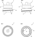
- FIG. 1A is a front view of the container 1 according to the first embodiment
- FIG. 1B is a vertical sectional view of the container main body 3 shown in FIG. 1A
- 2A is a front view of the cap 2
- FIG. 2B is a left side view of the cap 2
- FIG. 2C is a top view of the cap 2
- FIG. 2D is a bottom view of the cap 2.
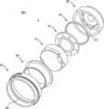
- FIG. 4 is an exploded view of the cap 2 when the cap 2 is viewed from obliquely above.
- FIG. 3 is an exploded view of the cap 2 when the cap 2 is viewed from obliquely below.
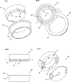
- 5A is a front view of the discharge port 20
- FIG. 5B is a bottom view of the discharge port 20
- FIG. 5C is a cross-sectional view taken along the line AA shown in FIG. 5B.
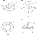
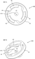
- 6A is an obliquely upper perspective view of the piston member 30
- FIG. 6B is a top view of the piston member 30
- FIG. 6C is an obliquely lower perspective view of the piston member 30,
- FIG. 6D is BB shown in FIG. 6B.
- 7A is an obliquely lower perspective view of the base body 10 and the inner cylindrical part 50
- FIG. 7B is an oblique upper perspective view of the base body 10 and the inner cylindrical part 50
- FIG. FIG. 7D is a front view of the unit 50
- FIG. 7D is a diagonally lower cross-sectional view showing a state where the base unit 10 is cut along the CC plane shown in FIG. 7C and the base unit 10 is separated.
- FIG. 4 is a vertical sectional view of the cap 2 when the cap 2 is viewed from obliquely above.
- FIG. 4 is a vertical sectional view of the cap 2 when the cap 2 is viewed from obliquely below.
- FIG. 6 is a 90-degree cross-sectional view of the cap 2 in a state where the discharge port portion 20 and the annular portion 40 are removed from the cap 2.
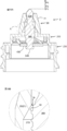
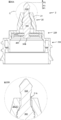
- FIG. 11A is a cross-sectional view showing a state in which the piston member 30 is advanced with respect to the discharge port 20, and FIG.
- FIG. 11B is a cross-sectional view showing a state in which the piston member 30 is retracted from the discharge port 20. It is an enlarged view of area A shown in Drawing 11B.
- FIG. 13A is a front view of the container 1 according to the second embodiment
- FIG. 13B is a vertical sectional view of the container body 3 shown in FIG. 13A. It is an exploded perspective view of cap 2 of container 1 concerning an embodiment of a 2nd viewpoint.
- FIG. 15 is a vertical sectional view of the discharge port portion 20.
- FIG. 3 is a front view of a piston 300.
- FIG. 17A is a top view of the urging unit 400
- FIG. 17B is a perspective view of the urging unit 400.
- FIG. 18A is a sectional view of the cap 2 when the piston 300 is at the closing position P1
- FIG. 18B is an enlarged view of a region A shown in FIG. 18A
- FIG. 19A is a sectional view of the cap 2 when the piston 300 is at the measuring position P2
- FIG. 19B is an enlarged view of a region B shown in FIG. 19A
- FIG. 20A is a sectional view of the cap 2 when the piston 300 is at the open position P3
- FIG. 20B is an enlarged view of a region C shown in FIG. 20A.
- upper (upper) and lower (lower) mean upper (upper) and lower (lower) in a state where the container body 3 is erected as shown in FIG. .
- the container 1 includes a cap 2 and a container body 3.
- the container body 3 is provided with an accommodating section 3A for accommodating the contents and an opening 3B for discharging the contents from the accommodating section 3A.
- the cap 2 is attached to the mouth 3B.
- the container main body 3 includes an outer shell 4 and an inner bag 5 in the housing 3A and the mouth 3B.
- the container body 3 is made of resin, and the container body 3 is configured to contract when the user presses it, and then to recover from the contracted state.
- the inner bag 5 peels off from the outer shell 4 as the content decreases, the inner bag 5 contracts and the inner bag 5 separates from the outer shell 4.
- the outer shell 4 is formed thicker than the inner bag 5 so that the resilience is enhanced.
- an outer air introduction hole 3c is formed in the concave portion 3a provided in the housing portion 3A to communicate an intermediate space between the outer shell 4 and the inner bag 5 and the outer space of the container body 3. .
- a valve member or the like for adjusting the flow of air into and out of the space between the outer shell 4 and the inner bag 5 can be attached to the outside air introduction hole 3c. Instead of providing the outside air introduction hole 3c, a gap may be provided between the outer shell 4 and the inner bag 5 to introduce outside air.
- An engagement portion 3b is formed in the mouth 3B.
- the engagement portion 3b is a ring-shaped projection that is engaged with the protrusion 64 (see FIGS. 3 and 4) of the cap 2.
- a stopper type cap 2 is attached to the container body 3 according to the embodiment. Note that the cap 2 may be in a form of being mounted on the container body 3 by a screw type.
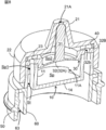
- the cap 2 includes a base portion 10, a discharge port portion 20, a piston member 30, an annular portion 40, an inner cylindrical portion 50, and an outer cylindrical shape. And a unit 60. Further, as shown in FIGS. 8 to 10, an inner space Sp, a flow channel Sp1, a flow channel St, and a flow channel Sp2 are formed inside the cap 2.
- the flow channel Sp1 is formed in an annular shape, and the flow channel St is formed to extend in the up-down direction.
- the flow path Sp2 and the internal space Sp are vertically divided by the piston member 30.
- the channel Sp1 is provided closer to the container body 3 than the channel Sp2.
- the channel St is provided closer to the container body 3 than the channel Sp1.
- the channel Sp1 corresponds to the first channel
- the channel Sp2 corresponds to the second channel.
- the atmosphere communication passage 15 and the internal space Sp communicate with each other, and the pressure in the internal space Sp is atmospheric pressure.
- the base portion 10 includes a first wall portion 11, a second wall portion 12, a first bottom portion 13, a second bottom portion 14, an atmosphere communication passage 15, a columnar portion 16, And
- the base portion 10 has an internal space Sp, a flow channel Sp1, and a flow channel St formed therein.
- the internal space Sp is disposed inside the flow channel Sp1.
- the base portion 10 is configured such that the internal space Sp and the flow path Sp1 do not communicate with each other, and is configured such that the internal space Sp and the flow path Sp2 do not communicate with each other.
- the first wall 11 is a cylindrical wall standing on the first bottom 13.
- the first wall portion 11 partitions the internal space Sp and the flow path Sp1.
- a flow channel Sp1 is formed between the first wall portion 11 and the second wall portion 12.
- the first wall portion 11 has a cutout portion 11A formed at a position where the internal space Sp and the atmosphere communication passage 15 communicate with each other.
- the second wall 12 is a cylindrical wall standing upright on the first bottom 13, and the second wall 12 is disposed outside the first wall 11.
- the second wall 12 partitions the flow channel Sp1 and the outside of the container 1.
- the first bottom 13 is an arc-shaped plate
- the second bottom 14 is a substantially circular plate.
- An atmosphere communication path 15 is formed between the first bottom 13 and the second bottom 14.
- the second bottom portion 14 has a cutout portion 14A, and the columnar portion 16 stands on the cutout portion 14A.
- the column 16 is formed to extend from the upper surface of the second bottom 14 to the lower surface of the first bottom 13, and a flow path St is formed in the column 16.
- the pressure in the internal space Sp tends to fluctuate due to the influence of the outside air temperature, and the possibility that the piston 31 does not operate properly increases.
- the atmosphere communication passage 15 communicates with the internal space Sp, the pressure of the internal space Sp is maintained at the atmospheric pressure. For this reason, the pressure in the internal space Sp is unlikely to fluctuate due to the outside air temperature, and the malfunction of the piston 31 is avoided.
- the discharge port portion 20 includes a nozzle 21, a cylindrical portion 22, and a convex portion 23.
- the nozzle 21 is a cylindrical member that tapers from a base end side to a distal end side, and a piston member 30 is provided inside the nozzle 21.
- a discharge port 21A is formed in the nozzle 21, and the discharge port 21A allows the contents contained in the container 1 to flow out of the container 1.
- the tubular portion 22 is formed in a cylindrical shape, and is connected to the base end side of the nozzle 21.
- the base portion 10, the piston member 30, and the annular portion 40 are provided inside the cylindrical portion 22. As shown in FIGS. 8 and 9, the base portion 10 is fitted into the cylindrical portion 22.
- the convex portion 23 has a function of preventing the piston member 30 from separating from the base portion 10. This function will be described later in the description of the annular portion 40.
- the protrusions 23 are formed in an arc shape, and the plurality of protrusions 23 are arranged in the circumferential direction around the piston 31.
- the plurality of convex portions 23 are arranged at equal intervals. A gap is formed between a pair of adjacent projections 23, and the content that has passed through the through hole 32b of the piston member 30 flows into the flow path Sp2 through the gap.
- the piston member 30 includes a piston 31 and an urging portion 32.
- the piston 31 is a long rod-shaped member.
- the distal end of the piston 31 is formed in a hemispherical shape, and the proximal end of the piston 31 is connected to the urging portion 32.
- the piston 31 closes the discharge port 21A.
- the tip of the piston 31 does not protrude above the discharge port 21A of the nozzle 21.
- the piston 31 is housed in the discharge port portion 20, so that the piston 31 is less likely to be exposed to external bacteria and the like.
- the urging portion 32 includes a plate-shaped portion 32A and a partition portion 32B.
- the urging portion 32 is made of, for example, an elastomer such as silicone rubber.
- the urging portion 32 is provided so as to partition the flow path Sp2 and the internal space Sp. That is, the urging portion 32 receives pressure from the flow channel Sp2 side and receives pressure from the internal space Sp side.
- the plate-like portion 32A is configured to be elastically deformed by a change in the internal pressure in the container 1. As shown in FIGS. 11A and 11B, the elastic deformation of the plate-like portion 32 ⁇ / b> A causes the piston 31 to move up and down, that is, the piston 31 moves forward and backward with respect to the discharge port 20.
- the plate-like portion 32A is a plate-like body formed in a dome shape so as to protrude toward the discharge port 20 side (the nozzle 21 side). Since the plate-like portion 32A is formed in a dome shape, the shape of the plate-like portion 32A is reversed when the internal pressure of the flow channel Sp2 increases.
- the base end of the piston 31 is connected to the center of the plate-shaped portion 32A.
- the plate-like portion 32A has a circular shape in a top view.
- the partition part 32B is connected to the periphery of the plate part 32A.
- the partition 32B is a ring-shaped plate, and the partition 32B has a plurality of through holes 32b.
- the plurality of through holes 32b are arranged in a circumferential direction with the piston 31 as a center. Further, the plurality of through holes 32b are arranged at equal intervals.
- the partition 32B is provided so as to partition the flow channel Sp1 and the flow channel Sp2.
- the annular portion 40 is disposed between the partition 32 ⁇ / b> B and the inner surface of the discharge port 20.
- the annular portion 40 has a function of preventing the piston member 30 from being separated from the base portion 10 similarly to the convex portion 23. That is, even if the user presses the container body 3 and the lower surface of the partition 32B is pressed against the contents, the partition 32B abuts against the annular portion 40 and the convex portion 23, so that the piston member 30 is Separation is suppressed. As a result, communication between the flow path Sp1 and the internal space Sp is prevented.
- the annular portion 40 is arranged outside the through hole 32b of the partition 32B.
- the inner cylindrical portion 50 has a main body 51 and a flange 52.
- the main body 51 is formed in a cylindrical shape, and a flange 52 is connected to an end of the main body 51.
- the flange portion 52 is an annular body that projects in the radial direction of the inner cylindrical portion 50.
- the outer peripheral surface of the flange portion 52 is provided along the inner surface of the outer cylindrical portion 60, and the inner peripheral surface of the flange portion 52 is provided along the outer peripheral surface of the second bottom portion 14.
- the outer cylindrical portion 60 has a main body 61, a male screw 62, and a protrusion 64.
- the main body 61 is formed in a cylindrical shape, and the main body 61 accommodates the inner cylindrical part 50.
- a male screw part 62 is formed in a spiral shape on the outer peripheral surface of the main body part 61.
- the male screw portion 62 is configured to be screwed into a cover (not shown) that accommodates the cap 2.
- a gap 63 is formed between the main body 61 and the main body 51.
- the mouth 3B is inserted into the gap 63.
- the protruding portion 64 is an annular protruding portion formed to protrude toward the inner cylindrical portion 50 side. The protruding portion 64 is engaged with the engaging portion 3b of the mouth 3B.
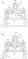
- the force (referred to as the urging force) of the urging portion 32 pressing the piston 31 against the nozzle 21 is a force (the retraction force) of pressing the urging portion 32 by the internal pressure of the flow path Sp2. ).
- the piston 31 closes the discharge port 21A of the nozzle 21.
- the urging force includes a force for pressing the urging portion 32 by the atmospheric pressure in the internal space Sp and an elastic force of the plate-shaped portion 32A.
- the urging force acting on the urging portion 32 becomes larger than the retreating force acting on the urging portion 32, and the shape of the plate-like portion 32A returns to its original shape.
- the piston 31 advances to the discharge port 20, and the discharge port 21A of the nozzle 21 is closed.
- the piston 31 advances to the discharge port 20 and the piston 31 pushes out the contents remaining in the nozzle 21.
- the liquid remaining in the discharge port 20 is suppressed.
- the piston 31 advances to the discharge port 20, and the discharge port 21A of the nozzle 21 is closed. This suppresses the contents that have flowed out of the container 1 from the discharge port 21A back into the nozzle 21.
- the cap 2 can more reliably prevent dust and bacteria from entering the container 1 together with the outflowing contents.
- the inside of the inner bag 5 may become negative pressure.
- the discharge port 21A is closed by the piston 31 in a state where the piston 31 is urged by the nozzle 21, even if the inside of the inner bag 5 becomes a negative pressure, it becomes difficult for air to enter the cap 2. ing.
- the cap 2 can more reliably prevent dust and bacteria from entering the container 1 together with the air.
- the container 1 includes a cap 2 and a container body 3.
- the container body 3 is provided with an accommodating section 3A for accommodating the contents and an opening 3B for discharging the contents from the accommodating section 3A.
- the cap 2 is attached to the mouth 3B.
- the container main body 3 includes an outer shell 4 and an inner bag 5 in the housing part 3A and the mouth part 3B.
- the container body 3 is made of resin, and the container body 3 is configured to contract when the user presses it, and then to recover from the contracted state.
- the inner bag 5 peels off from the outer shell 4 as the content decreases, the inner bag 5 contracts and the inner bag 5 separates from the outer shell 4.
- the outer shell 4 is formed thicker than the inner bag 5 so that the resilience is enhanced.
- an outer air introduction hole 3c is formed in the concave portion 3a provided in the housing portion 3A to communicate an intermediate space between the outer shell 4 and the inner bag 5 and the outer space of the container body 3. .
- a valve member or the like for adjusting the flow of air into and out of the space between the outer shell 4 and the inner bag 5 can be attached to the outside air introduction hole 3c. Instead of providing the outside air introduction hole 3c, a gap may be provided between the outer shell 4 and the inner bag 5 to introduce outside air.
- An engagement portion 3b is formed in the mouth 3B.
- the engagement portion 3b is a ring-shaped projection that is engaged with the projection 23B (see FIG. 15) of the cap 2.
- a stopper type cap 2 is attached to the container body 3 according to the embodiment. Note that the cap 2 may be in a form of being mounted on the container body 3 by a screw type.
- the cap 2 includes a discharge port portion 20, a piston 300, and an urging portion 400.
- the discharge port 20 includes a nozzle 21, an inner cylindrical part 220, and an outer cylindrical part 230.
- the closing position P1, the measuring position P2, and the opening position are sequentially arranged in the direction from the inside of the discharge port 20 toward the discharge port 21A.
- Position P3 is lined up.
- the closing position P1, the measuring position P2, and the opening position P3 are defined as the position of the tip of the piston 300 in the movement direction of the piston 300.
- the method of defining the closing position P1, the measuring position P2, and the opening position P3 is not limited to this.
- the nozzle 21 is a cylindrical member tapering from the base end to the tip end, and a piston 300 is provided inside the nozzle 21.
- a discharge port 21A is formed in the nozzle 21, and the discharge port 21A allows the contents contained in the container 1 to flow out of the container 1.
- the discharge port 21 ⁇ / b> A is closed by the piston 300 when the user does not press the container 1.
- a storage space 21 ⁇ / b> B is formed inside the nozzle 21 when the user does not press the container 1.
- the storage space 21B is formed from the base end of the nozzle 21 to the tip end side.
- the inner cylindrical portion 220 is a cylindrical member, and is connected to the base end side of the nozzle 21.
- the piston 300 and the urging portion 400 are provided inside the inner cylindrical portion 220.
- the inner cylindrical part 220 has a locking part 22A, a mounting surface part 22B, and a flange 22C.
- the locking portion 22A is provided annularly on the inner peripheral surface of the inner cylindrical portion 220. As shown in FIGS. 15 and 18A, the locking portion 22A protrudes toward the piston 300.
- the urging portion 400 is attached to the attachment surface portion 22B.
- the urging portion 400 is disposed between the locking portion 22A and the mounting surface portion 22B, and the urging portion 400 is disengaged from the inner cylindrical portion 220 by being locked by the locking portion 22A.
- the flange 22 ⁇ / b> C is formed in an annular shape on the outer peripheral surface of the inner cylindrical portion 220.
- the flange 22C is formed on the back side of the locking portion 22A.
- the outer tubular portion 230 is a cylindrical member, and is connected to the inner tubular portion 220.
- the outer cylindrical portion 230 is connected to the flange 22C of the inner cylindrical portion 220.
- the outer cylindrical part 230 has a male screw part 23A and a protruding part 23B.
- the male screw portion 23 ⁇ / b> A is configured to be screwed into a cover (not shown) that accommodates the cap 2.
- the protruding portion 23B is an annular protruding portion formed to protrude toward the inner cylindrical portion 220 side.
- the projecting portion 23B engages with the engaging portion 3b of the mouth 3B.
- the mouth 3B is inserted into the gap 23C between the inner cylindrical part 220 and the outer cylindrical part 230.
- the piston 300 includes a distal end portion 310, a first trunk portion 320, a second trunk portion 33, a proximal end portion 34, a gasket portion 35, and a guide portion 36.
- the piston 300 is a long rod-shaped member.
- the piston 300 is provided on the nozzle 21 such that the shaft 30A of the piston 300 is located on the shaft 20A of the nozzle 21.
- the piston 300 is configured such that the piston 300 moves from the closed position P1 to the open position P3.
- the piston 300 has a first function of closing the discharge port 21A of the nozzle 21, a second function of measuring a predetermined amount of contents, and a third function of discharging the predetermined amount of contents from inside the container 1 to outside the container 1. And a function.
- the second function is realized by the piston 300 being pressurized by the contents and the piston 300 moving forward.
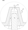
- the measurement space Sm for measuring the contents is formed between the piston 300 and the inner surface of the discharge port 20 by the advance of the piston 300.
- the measurement space Sm is a closed space.
- the tip 310 is formed so as to taper toward the tip. This makes it easy for the content that travels through the piston 300 to be dripped from the piston 300, and suppresses the content from being left attached to the piston 300, that is, the liquid remaining on the piston 300.
- the piston 300 is at the closed position P ⁇ b> 1, the distal end 310 is exposed from the nozzle 21.
- the first body 320 is a columnar member, and a gasket 35 and a guide 36 are provided on the outer peripheral surface of the first body 320.
- the gasket part 35 is provided on the first body part 320 in an annular shape.
- three gasket portions 35 are provided on the first body portion 320 so as to be arranged in the axial direction of the piston 300, but the number of the gasket portions 35 is not limited to three.
- the gasket portion 35 has a function of partitioning a space inside the cap 2 up and down.
- the guide part 36 extends in parallel with the longitudinal direction of the piston 300, and the guide part 36 is provided so as to intersect the gasket part 35.
- the piston 300 Since the guide portion 36 is provided on the piston 300, the piston 300 is unlikely to be tilted from the axis of the nozzle 21. As a result, when the piston 300 moves up and down, the axis of the piston 300 moves from above the axis of the nozzle 21. Departure is suppressed. That is, since the guide portion 36 is provided on the piston 300, the piston 300 more reliably moves straight. Thereby, the above-described first to third functions are more reliably exhibited.
- the gasket portion 35 slides on the inner surface of the nozzle 21.
- the posture of the gasket portion 35 is held by the guide portion 36. For this reason, when the gasket part 35 is sliding with respect to the inner surface of the nozzle 21, bending or deformation of the gasket part 35 is suppressed.
- the first body 320 has an inclined surface 320A.
- the inclined surface 320A is formed so as to be tapered in a direction from the base end portion 34 toward the distal end portion 310 side. Therefore, when the piston 300 is at the open position P3, the inclined surface 320A is in a state of protruding toward the tip of the nozzle 21. Therefore, as shown in FIGS. 19A and 20A, the contents of the measuring space Sm are more reliably pushed out by the inclined surface 320A, and the liquid remaining on the piston 300 is suppressed. Further, since the inclined surface 320A is formed on the piston 300, the formability of the piston 300 is improved.
- the measuring space Sm is a closed space formed by the gasket portion 35, a portion of the outer peripheral surface of the piston 300 above the gasket portion 35, and the inner surface of the nozzle 21.
- the gasket portion 35 is partitioned into a measuring space Sm (upper space) and a space on the container body 3 side (lower space).
- the second body 33 is a columnar member, and is provided closer to the distal end of the piston 300 than the first body 320.
- the second trunk portion 33 has an enlarged portion 33A.
- FIG. 18A when the piston 300 is at the closing position P ⁇ b> 1, the enlarged portion 33 ⁇ / b> A contacts the inner surface of the nozzle 21 and closes the discharge port 21 ⁇ / b> A of the discharge port 20. Further, as shown in FIG. 20A, when the piston 300 is at the open position P3, the enlarged portion 33A projects from the nozzle 21 to open the discharge port 21A.
- the base end portion 34 has a concave portion 34A and a pressing surface 34B.
- the concave portion 34A is formed in the piston 300 in an annular shape.
- the urging portion 400 is fitted into the concave portion 34A. Thereby, the base end portion 34 is fixed to the urging portion 400.
- the urging portion 400 includes a mounting portion 41, an arm portion 42, and a fixing portion 43.
- the urging section 400 is made of, for example, an elastomer such as silicone rubber.
- the urging unit 400 is configured to elastically deform when the piston 300 moves due to a change in the internal pressure in the container 1.
- An opening 41A into which the base end portion 34 is inserted is formed in the attachment portion 41, and an edge of the opening portion 41A is fitted into a concave portion 34A of the base end portion 34.
- Three arm portions 42 are connected to the mounting portion 41 such that adjacent arm portions 42 form an angle of 120 degrees. Note that the number of the arm portions 42 is not limited to three.
- One end of the arm portion 42 is connected to the attachment portion 41, and the other end of the arm portion 42 is connected to the fixing portion 43.
- one end of the arm 42 is disposed below the other end of the arm 42.
- a gap 44 is formed between the mounting portion 41, the arm portion 42, and the fixing portion 43. The contents pass through the gap 44 and reach the nozzle 21.
- the fixing part 43 is an annular member.
- the fixing portion 43 is disposed between the locking portion 22A and the mounting surface portion 22B, and the fixing portion 43 is locked by the locking portion 22A.
- the measuring position P2 is a position where the gasket portion 35 starts to separate the measuring space Sm (upper space) and the space on the container body 3 side (lower space).
- the measuring space Sm is filled with the contents. Since the measuring space Sm is a closed space having a predetermined volume, the amount of the contents in the measuring space Sm is also a predetermined amount.
- the pressurizing surface 34B of the piston 300 is further pressurized by the contents, and the piston 300 moves from the measuring position P2 to the open position P3.
- the discharge port 21A of the nozzle 21 is opened, and the measuring space Sm and the outside of the container 1 communicate.
- the measurement space Sm is filled with the piston 300 so that the volume of the measurement space Sm decreases. That is, the contents of the measuring space Sm are pushed out of the container 1 by the piston 300.
- the piston 300 moves from the open position P3 to the closed position P1 by the action of the urging portion 400.
- the measurement space Sm is a closed space, but is not limited thereto.
- a gap may be formed between the piston 300 and the inner surface of the tip of the nozzle 21. That is, when the piston 300 is at the measurement position P2, the measurement space Sm may communicate with the outside of the container 1. Even if the user tilts the container 1 when the piston 300 is at the measuring position P2, the contents have surface tension, so that the contents of the measuring space Sm are between the piston 300 and the inner surface of the tip of the nozzle 21. Outflow from the formed gap is suppressed.
Landscapes
- Engineering & Computer Science (AREA)
- Mechanical Engineering (AREA)
- Closures For Containers (AREA)
Abstract
Le but de la présente invention est de fournir un récipient et un capuchon qui empêchent un liquide d'être laissé de côté. L'invention concerne un récipient qui comprend : un corps de récipient qui loge un contenu ; et un capuchon qui est monté sur le corps de récipient. Le capuchon comprend une partie orifice d'évacuation et un piston. Le piston : ouvre la partie orifice d'évacuation en s'éloignant de la partie orifice d'évacuation en association avec une augmentation de la pression interne du corps de récipient ; et obstrue la partie orifice d'évacuation en se déplaçant vers la partie orifice d'évacuation en association avec une diminution de la pression interne.
Applications Claiming Priority (4)
| Application Number | Priority Date | Filing Date | Title |
|---|---|---|---|
| JP2018123971A JP7137052B2 (ja) | 2018-06-29 | 2018-06-29 | 容器及びキャップ |
| JP2018-123969 | 2018-06-29 | ||
| JP2018-123971 | 2018-06-29 | ||
| JP2018123969A JP2020001767A (ja) | 2018-06-29 | 2018-06-29 | 容器及びキャップ |
Publications (1)
| Publication Number | Publication Date |
|---|---|
| WO2020004642A1 true WO2020004642A1 (fr) | 2020-01-02 |
Family
ID=68987220
Family Applications (1)
| Application Number | Title | Priority Date | Filing Date |
|---|---|---|---|
| PCT/JP2019/025905 Ceased WO2020004642A1 (fr) | 2018-06-29 | 2019-06-28 | Récipient et capuchon |
Country Status (2)
| Country | Link |
|---|---|
| TW (1) | TW202005877A (fr) |
| WO (1) | WO2020004642A1 (fr) |
Citations (6)
| Publication number | Priority date | Publication date | Assignee | Title |
|---|---|---|---|---|
| JPS4962213U (fr) * | 1972-09-09 | 1974-05-31 | ||
| JPS5571280A (en) * | 1978-10-31 | 1980-05-29 | Containaire Inc | Extrusion container |
| WO2011099309A1 (fr) * | 2010-02-15 | 2011-08-18 | Abe Shuntaro | Réceptacle de stockage et des fluide et son couvercle |
| US20170096266A1 (en) * | 2014-05-27 | 2017-04-06 | Bormioli Rocco S.P.A. | Dispenser |
| JP2017081636A (ja) * | 2015-10-30 | 2017-05-18 | 株式会社吉野工業所 | 注出キャップ及び注出容器 |
| JP2017197264A (ja) * | 2016-04-28 | 2017-11-02 | 株式会社吉野工業所 | 定量注出容器 |
-
2019
- 2019-06-28 WO PCT/JP2019/025905 patent/WO2020004642A1/fr not_active Ceased
- 2019-07-01 TW TW108123119A patent/TW202005877A/zh unknown
Patent Citations (6)
| Publication number | Priority date | Publication date | Assignee | Title |
|---|---|---|---|---|
| JPS4962213U (fr) * | 1972-09-09 | 1974-05-31 | ||
| JPS5571280A (en) * | 1978-10-31 | 1980-05-29 | Containaire Inc | Extrusion container |
| WO2011099309A1 (fr) * | 2010-02-15 | 2011-08-18 | Abe Shuntaro | Réceptacle de stockage et des fluide et son couvercle |
| US20170096266A1 (en) * | 2014-05-27 | 2017-04-06 | Bormioli Rocco S.P.A. | Dispenser |
| JP2017081636A (ja) * | 2015-10-30 | 2017-05-18 | 株式会社吉野工業所 | 注出キャップ及び注出容器 |
| JP2017197264A (ja) * | 2016-04-28 | 2017-11-02 | 株式会社吉野工業所 | 定量注出容器 |
Also Published As
| Publication number | Publication date |
|---|---|
| TW202005877A (zh) | 2020-02-01 |
Similar Documents
| Publication | Publication Date | Title |
|---|---|---|
| KR101930278B1 (ko) | 토출 용기 | |
| JP6397401B2 (ja) | プッシュタイプディスペンサー | |
| EP3805127B1 (fr) | Pulvérisateur de liquide de type à gâchette | |
| KR20160111165A (ko) | 디스펜서 | |
| JP7033989B2 (ja) | 吐出器 | |
| JP7158253B2 (ja) | 吐出器 | |
| JP2019014531A (ja) | キャップ及び吐出容器 | |
| JP6349221B2 (ja) | 計量容器 | |
| JP7137052B2 (ja) | 容器及びキャップ | |
| JP6429673B2 (ja) | 注出キャップ及びそれを備える容器 | |
| JP6820169B2 (ja) | 吐出容器 | |
| JP4743389B2 (ja) | 少量吐出容器 | |
| JP6560906B2 (ja) | 吐出容器 | |
| JP6421079B2 (ja) | スポイト容器 | |
| JP2020001767A (ja) | 容器及びキャップ | |
| JP7481623B2 (ja) | ノズル及びこれを備えた吐出容器 | |
| JP2023125551A (ja) | 吐出器 | |
| JP5944662B2 (ja) | 詰め替え用注出キャップ | |
| JP6991679B2 (ja) | オーバーキャップ付き容器 | |
| JP7239384B2 (ja) | キャップ | |
| JP7450490B2 (ja) | 吐出容器 | |
| KR101213047B1 (ko) | 에어 캡 및 이를 구비하는 용기 | |
| JP4573119B2 (ja) | 少量吐出容器 | |
| TW202005877A (zh) | 容器及帽蓋 | |
| JP4530692B2 (ja) | キャップ付き容器 |
Legal Events
| Date | Code | Title | Description |
|---|---|---|---|
| 121 | Ep: the epo has been informed by wipo that ep was designated in this application |
Ref document number: 19827372 Country of ref document: EP Kind code of ref document: A1 |
|
| NENP | Non-entry into the national phase |
Ref country code: DE |
|
| 122 | Ep: pct application non-entry in european phase |
Ref document number: 19827372 Country of ref document: EP Kind code of ref document: A1 |