WO2020004674A1 - 多孔質炭素の製造方法及びこの製造方法により製造された多孔質炭素を含む電極及び触媒担体 - Google Patents
多孔質炭素の製造方法及びこの製造方法により製造された多孔質炭素を含む電極及び触媒担体 Download PDFInfo
- Publication number
- WO2020004674A1 WO2020004674A1 PCT/JP2019/026199 JP2019026199W WO2020004674A1 WO 2020004674 A1 WO2020004674 A1 WO 2020004674A1 JP 2019026199 W JP2019026199 W JP 2019026199W WO 2020004674 A1 WO2020004674 A1 WO 2020004674A1
- Authority
- WO
- WIPO (PCT)
- Prior art keywords
- template
- carbon
- amount
- functional group
- fired body
- Prior art date
- Legal status (The legal status is an assumption and is not a legal conclusion. Google has not performed a legal analysis and makes no representation as to the accuracy of the status listed.)
- Ceased
Links
- HGCIXCUEYOPUTN-UHFFFAOYSA-N C1CC=CCC1 Chemical compound C1CC=CCC1 HGCIXCUEYOPUTN-UHFFFAOYSA-N 0.000 description 1
Images






Classifications
-
- B—PERFORMING OPERATIONS; TRANSPORTING
- B01—PHYSICAL OR CHEMICAL PROCESSES OR APPARATUS IN GENERAL
- B01J—CHEMICAL OR PHYSICAL PROCESSES, e.g. CATALYSIS OR COLLOID CHEMISTRY; THEIR RELEVANT APPARATUS
- B01J20/00—Solid sorbent compositions or filter aid compositions; Sorbents for chromatography; Processes for preparing, regenerating or reactivating thereof
- B01J20/30—Processes for preparing, regenerating, or reactivating
- B01J20/305—Addition of material, later completely removed, e.g. as result of heat treatment, leaching or washing, e.g. for forming pores
- B01J20/3057—Use of a templating or imprinting material ; filling pores of a substrate or matrix followed by the removal of the substrate or matrix
-
- C—CHEMISTRY; METALLURGY
- C01—INORGANIC CHEMISTRY
- C01B—NON-METALLIC ELEMENTS; COMPOUNDS THEREOF; METALLOIDS OR COMPOUNDS THEREOF NOT COVERED BY SUBCLASS C01C
- C01B32/00—Carbon; Compounds thereof
- C01B32/30—Active carbon
- C01B32/312—Preparation
- C01B32/318—Preparation characterised by the starting materials
-
- B—PERFORMING OPERATIONS; TRANSPORTING
- B01—PHYSICAL OR CHEMICAL PROCESSES OR APPARATUS IN GENERAL
- B01J—CHEMICAL OR PHYSICAL PROCESSES, e.g. CATALYSIS OR COLLOID CHEMISTRY; THEIR RELEVANT APPARATUS
- B01J20/00—Solid sorbent compositions or filter aid compositions; Sorbents for chromatography; Processes for preparing, regenerating or reactivating thereof
- B01J20/02—Solid sorbent compositions or filter aid compositions; Sorbents for chromatography; Processes for preparing, regenerating or reactivating thereof comprising inorganic material
- B01J20/20—Solid sorbent compositions or filter aid compositions; Sorbents for chromatography; Processes for preparing, regenerating or reactivating thereof comprising inorganic material comprising free carbon; comprising carbon obtained by carbonising processes
-
- B—PERFORMING OPERATIONS; TRANSPORTING
- B01—PHYSICAL OR CHEMICAL PROCESSES OR APPARATUS IN GENERAL
- B01J—CHEMICAL OR PHYSICAL PROCESSES, e.g. CATALYSIS OR COLLOID CHEMISTRY; THEIR RELEVANT APPARATUS
- B01J20/00—Solid sorbent compositions or filter aid compositions; Sorbents for chromatography; Processes for preparing, regenerating or reactivating thereof
- B01J20/28—Solid sorbent compositions or filter aid compositions; Sorbents for chromatography; Processes for preparing, regenerating or reactivating thereof characterised by their form or physical properties
- B01J20/28054—Solid sorbent compositions or filter aid compositions; Sorbents for chromatography; Processes for preparing, regenerating or reactivating thereof characterised by their form or physical properties characterised by their surface properties or porosity
- B01J20/28057—Surface area, e.g. B.E.T specific surface area
-
- B—PERFORMING OPERATIONS; TRANSPORTING
- B01—PHYSICAL OR CHEMICAL PROCESSES OR APPARATUS IN GENERAL
- B01J—CHEMICAL OR PHYSICAL PROCESSES, e.g. CATALYSIS OR COLLOID CHEMISTRY; THEIR RELEVANT APPARATUS
- B01J20/00—Solid sorbent compositions or filter aid compositions; Sorbents for chromatography; Processes for preparing, regenerating or reactivating thereof
- B01J20/28—Solid sorbent compositions or filter aid compositions; Sorbents for chromatography; Processes for preparing, regenerating or reactivating thereof characterised by their form or physical properties
- B01J20/28054—Solid sorbent compositions or filter aid compositions; Sorbents for chromatography; Processes for preparing, regenerating or reactivating thereof characterised by their form or physical properties characterised by their surface properties or porosity
- B01J20/28069—Pore volume, e.g. total pore volume, mesopore volume, micropore volume
-
- B—PERFORMING OPERATIONS; TRANSPORTING
- B01—PHYSICAL OR CHEMICAL PROCESSES OR APPARATUS IN GENERAL
- B01J—CHEMICAL OR PHYSICAL PROCESSES, e.g. CATALYSIS OR COLLOID CHEMISTRY; THEIR RELEVANT APPARATUS
- B01J20/00—Solid sorbent compositions or filter aid compositions; Sorbents for chromatography; Processes for preparing, regenerating or reactivating thereof
- B01J20/28—Solid sorbent compositions or filter aid compositions; Sorbents for chromatography; Processes for preparing, regenerating or reactivating thereof characterised by their form or physical properties
- B01J20/28054—Solid sorbent compositions or filter aid compositions; Sorbents for chromatography; Processes for preparing, regenerating or reactivating thereof characterised by their form or physical properties characterised by their surface properties or porosity
- B01J20/28078—Pore diameter
- B01J20/2808—Pore diameter being less than 2 nm, i.e. micropores or nanopores
-
- B—PERFORMING OPERATIONS; TRANSPORTING
- B01—PHYSICAL OR CHEMICAL PROCESSES OR APPARATUS IN GENERAL
- B01J—CHEMICAL OR PHYSICAL PROCESSES, e.g. CATALYSIS OR COLLOID CHEMISTRY; THEIR RELEVANT APPARATUS
- B01J20/00—Solid sorbent compositions or filter aid compositions; Sorbents for chromatography; Processes for preparing, regenerating or reactivating thereof
- B01J20/28—Solid sorbent compositions or filter aid compositions; Sorbents for chromatography; Processes for preparing, regenerating or reactivating thereof characterised by their form or physical properties
- B01J20/28054—Solid sorbent compositions or filter aid compositions; Sorbents for chromatography; Processes for preparing, regenerating or reactivating thereof characterised by their form or physical properties characterised by their surface properties or porosity
- B01J20/28078—Pore diameter
- B01J20/28083—Pore diameter being in the range 2-50 nm, i.e. mesopores
-
- B—PERFORMING OPERATIONS; TRANSPORTING
- B01—PHYSICAL OR CHEMICAL PROCESSES OR APPARATUS IN GENERAL
- B01J—CHEMICAL OR PHYSICAL PROCESSES, e.g. CATALYSIS OR COLLOID CHEMISTRY; THEIR RELEVANT APPARATUS
- B01J20/00—Solid sorbent compositions or filter aid compositions; Sorbents for chromatography; Processes for preparing, regenerating or reactivating thereof
- B01J20/30—Processes for preparing, regenerating, or reactivating
-
- B—PERFORMING OPERATIONS; TRANSPORTING
- B01—PHYSICAL OR CHEMICAL PROCESSES OR APPARATUS IN GENERAL
- B01J—CHEMICAL OR PHYSICAL PROCESSES, e.g. CATALYSIS OR COLLOID CHEMISTRY; THEIR RELEVANT APPARATUS
- B01J20/00—Solid sorbent compositions or filter aid compositions; Sorbents for chromatography; Processes for preparing, regenerating or reactivating thereof
- B01J20/30—Processes for preparing, regenerating, or reactivating
- B01J20/3078—Thermal treatment, e.g. calcining or pyrolizing
-
- B—PERFORMING OPERATIONS; TRANSPORTING
- B01—PHYSICAL OR CHEMICAL PROCESSES OR APPARATUS IN GENERAL
- B01J—CHEMICAL OR PHYSICAL PROCESSES, e.g. CATALYSIS OR COLLOID CHEMISTRY; THEIR RELEVANT APPARATUS
- B01J35/00—Catalysts, in general, characterised by their form or physical properties
- B01J35/60—Catalysts, in general, characterised by their form or physical properties characterised by their surface properties or porosity
- B01J35/61—Surface area
- B01J35/615—100-500 m2/g
-
- B—PERFORMING OPERATIONS; TRANSPORTING
- B01—PHYSICAL OR CHEMICAL PROCESSES OR APPARATUS IN GENERAL
- B01J—CHEMICAL OR PHYSICAL PROCESSES, e.g. CATALYSIS OR COLLOID CHEMISTRY; THEIR RELEVANT APPARATUS
- B01J35/00—Catalysts, in general, characterised by their form or physical properties
- B01J35/60—Catalysts, in general, characterised by their form or physical properties characterised by their surface properties or porosity
- B01J35/61—Surface area
- B01J35/617—500-1000 m2/g
-
- B—PERFORMING OPERATIONS; TRANSPORTING
- B01—PHYSICAL OR CHEMICAL PROCESSES OR APPARATUS IN GENERAL
- B01J—CHEMICAL OR PHYSICAL PROCESSES, e.g. CATALYSIS OR COLLOID CHEMISTRY; THEIR RELEVANT APPARATUS
- B01J35/00—Catalysts, in general, characterised by their form or physical properties
- B01J35/60—Catalysts, in general, characterised by their form or physical properties characterised by their surface properties or porosity
- B01J35/61—Surface area
- B01J35/618—Surface area more than 1000 m2/g
-
- B—PERFORMING OPERATIONS; TRANSPORTING
- B01—PHYSICAL OR CHEMICAL PROCESSES OR APPARATUS IN GENERAL
- B01J—CHEMICAL OR PHYSICAL PROCESSES, e.g. CATALYSIS OR COLLOID CHEMISTRY; THEIR RELEVANT APPARATUS
- B01J35/00—Catalysts, in general, characterised by their form or physical properties
- B01J35/60—Catalysts, in general, characterised by their form or physical properties characterised by their surface properties or porosity
- B01J35/63—Pore volume
- B01J35/633—Pore volume less than 0.5 ml/g
-
- B—PERFORMING OPERATIONS; TRANSPORTING
- B01—PHYSICAL OR CHEMICAL PROCESSES OR APPARATUS IN GENERAL
- B01J—CHEMICAL OR PHYSICAL PROCESSES, e.g. CATALYSIS OR COLLOID CHEMISTRY; THEIR RELEVANT APPARATUS
- B01J35/00—Catalysts, in general, characterised by their form or physical properties
- B01J35/60—Catalysts, in general, characterised by their form or physical properties characterised by their surface properties or porosity
- B01J35/63—Pore volume
- B01J35/635—0.5-1.0 ml/g
-
- B—PERFORMING OPERATIONS; TRANSPORTING
- B01—PHYSICAL OR CHEMICAL PROCESSES OR APPARATUS IN GENERAL
- B01J—CHEMICAL OR PHYSICAL PROCESSES, e.g. CATALYSIS OR COLLOID CHEMISTRY; THEIR RELEVANT APPARATUS
- B01J35/00—Catalysts, in general, characterised by their form or physical properties
- B01J35/60—Catalysts, in general, characterised by their form or physical properties characterised by their surface properties or porosity
- B01J35/63—Pore volume
- B01J35/638—Pore volume more than 1.0 ml/g
-
- B—PERFORMING OPERATIONS; TRANSPORTING
- B01—PHYSICAL OR CHEMICAL PROCESSES OR APPARATUS IN GENERAL
- B01J—CHEMICAL OR PHYSICAL PROCESSES, e.g. CATALYSIS OR COLLOID CHEMISTRY; THEIR RELEVANT APPARATUS
- B01J35/00—Catalysts, in general, characterised by their form or physical properties
- B01J35/60—Catalysts, in general, characterised by their form or physical properties characterised by their surface properties or porosity
- B01J35/64—Pore diameter
- B01J35/647—2-50 nm
-
- B—PERFORMING OPERATIONS; TRANSPORTING
- B01—PHYSICAL OR CHEMICAL PROCESSES OR APPARATUS IN GENERAL
- B01J—CHEMICAL OR PHYSICAL PROCESSES, e.g. CATALYSIS OR COLLOID CHEMISTRY; THEIR RELEVANT APPARATUS
- B01J35/00—Catalysts, in general, characterised by their form or physical properties
- B01J35/60—Catalysts, in general, characterised by their form or physical properties characterised by their surface properties or porosity
- B01J35/64—Pore diameter
- B01J35/651—50-500 nm
-
- C—CHEMISTRY; METALLURGY
- C01—INORGANIC CHEMISTRY
- C01B—NON-METALLIC ELEMENTS; COMPOUNDS THEREOF; METALLOIDS OR COMPOUNDS THEREOF NOT COVERED BY SUBCLASS C01C
- C01B32/00—Carbon; Compounds thereof
- C01B32/30—Active carbon
- C01B32/354—After-treatment
-
- H—ELECTRICITY
- H01—ELECTRIC ELEMENTS
- H01M—PROCESSES OR MEANS, e.g. BATTERIES, FOR THE DIRECT CONVERSION OF CHEMICAL ENERGY INTO ELECTRICAL ENERGY
- H01M4/00—Electrodes
- H01M4/02—Electrodes composed of, or comprising, active material
- H01M4/36—Selection of substances as active materials, active masses, active liquids
- H01M4/58—Selection of substances as active materials, active masses, active liquids of inorganic compounds other than oxides or hydroxides, e.g. sulfides, selenides, tellurides, halogenides or LiCoFy; of polyanionic structures, e.g. phosphates, silicates or borates
- H01M4/583—Carbonaceous material, e.g. graphite-intercalation compounds or CFx
-
- H—ELECTRICITY
- H01—ELECTRIC ELEMENTS
- H01M—PROCESSES OR MEANS, e.g. BATTERIES, FOR THE DIRECT CONVERSION OF CHEMICAL ENERGY INTO ELECTRICAL ENERGY
- H01M4/00—Electrodes
- H01M4/02—Electrodes composed of, or comprising, active material
- H01M4/36—Selection of substances as active materials, active masses, active liquids
- H01M4/58—Selection of substances as active materials, active masses, active liquids of inorganic compounds other than oxides or hydroxides, e.g. sulfides, selenides, tellurides, halogenides or LiCoFy; of polyanionic structures, e.g. phosphates, silicates or borates
- H01M4/583—Carbonaceous material, e.g. graphite-intercalation compounds or CFx
- H01M4/587—Carbonaceous material, e.g. graphite-intercalation compounds or CFx for inserting or intercalating light metals
-
- H—ELECTRICITY
- H01—ELECTRIC ELEMENTS
- H01M—PROCESSES OR MEANS, e.g. BATTERIES, FOR THE DIRECT CONVERSION OF CHEMICAL ENERGY INTO ELECTRICAL ENERGY
- H01M4/00—Electrodes
- H01M4/02—Electrodes composed of, or comprising, active material
- H01M4/62—Selection of inactive substances as ingredients for active masses, e.g. binders, fillers
- H01M4/624—Electric conductive fillers
- H01M4/625—Carbon or graphite
-
- C—CHEMISTRY; METALLURGY
- C01—INORGANIC CHEMISTRY
- C01P—INDEXING SCHEME RELATING TO STRUCTURAL AND PHYSICAL ASPECTS OF SOLID INORGANIC COMPOUNDS
- C01P2006/00—Physical properties of inorganic compounds
- C01P2006/12—Surface area
-
- C—CHEMISTRY; METALLURGY
- C01—INORGANIC CHEMISTRY
- C01P—INDEXING SCHEME RELATING TO STRUCTURAL AND PHYSICAL ASPECTS OF SOLID INORGANIC COMPOUNDS
- C01P2006/00—Physical properties of inorganic compounds
- C01P2006/14—Pore volume
-
- C—CHEMISTRY; METALLURGY
- C01—INORGANIC CHEMISTRY
- C01P—INDEXING SCHEME RELATING TO STRUCTURAL AND PHYSICAL ASPECTS OF SOLID INORGANIC COMPOUNDS
- C01P2006/00—Physical properties of inorganic compounds
- C01P2006/16—Pore diameter
-
- H—ELECTRICITY
- H01—ELECTRIC ELEMENTS
- H01M—PROCESSES OR MEANS, e.g. BATTERIES, FOR THE DIRECT CONVERSION OF CHEMICAL ENERGY INTO ELECTRICAL ENERGY
- H01M10/00—Secondary cells; Manufacture thereof
- H01M10/05—Accumulators with non-aqueous electrolyte
- H01M10/052—Li-accumulators
-
- H—ELECTRICITY
- H01—ELECTRIC ELEMENTS
- H01M—PROCESSES OR MEANS, e.g. BATTERIES, FOR THE DIRECT CONVERSION OF CHEMICAL ENERGY INTO ELECTRICAL ENERGY
- H01M10/00—Secondary cells; Manufacture thereof
- H01M10/05—Accumulators with non-aqueous electrolyte
- H01M10/052—Li-accumulators
- H01M10/0525—Rocking-chair batteries, i.e. batteries with lithium insertion or intercalation in both electrodes; Lithium-ion batteries
-
- H—ELECTRICITY
- H01—ELECTRIC ELEMENTS
- H01M—PROCESSES OR MEANS, e.g. BATTERIES, FOR THE DIRECT CONVERSION OF CHEMICAL ENERGY INTO ELECTRICAL ENERGY
- H01M10/00—Secondary cells; Manufacture thereof
- H01M10/05—Accumulators with non-aqueous electrolyte
- H01M10/054—Accumulators with insertion or intercalation of metals other than lithium, e.g. with magnesium or aluminium
-
- H—ELECTRICITY
- H01—ELECTRIC ELEMENTS
- H01M—PROCESSES OR MEANS, e.g. BATTERIES, FOR THE DIRECT CONVERSION OF CHEMICAL ENERGY INTO ELECTRICAL ENERGY
- H01M10/00—Secondary cells; Manufacture thereof
- H01M10/06—Lead-acid accumulators
-
- H—ELECTRICITY
- H01—ELECTRIC ELEMENTS
- H01M—PROCESSES OR MEANS, e.g. BATTERIES, FOR THE DIRECT CONVERSION OF CHEMICAL ENERGY INTO ELECTRICAL ENERGY
- H01M10/00—Secondary cells; Manufacture thereof
- H01M10/34—Gastight accumulators
-
- H—ELECTRICITY
- H01—ELECTRIC ELEMENTS
- H01M—PROCESSES OR MEANS, e.g. BATTERIES, FOR THE DIRECT CONVERSION OF CHEMICAL ENERGY INTO ELECTRICAL ENERGY
- H01M12/00—Hybrid cells; Manufacture thereof
- H01M12/04—Hybrid cells; Manufacture thereof composed of a half-cell of the fuel-cell type and of a half-cell of the primary-cell type
- H01M12/06—Hybrid cells; Manufacture thereof composed of a half-cell of the fuel-cell type and of a half-cell of the primary-cell type with one metallic and one gaseous electrode
-
- Y—GENERAL TAGGING OF NEW TECHNOLOGICAL DEVELOPMENTS; GENERAL TAGGING OF CROSS-SECTIONAL TECHNOLOGIES SPANNING OVER SEVERAL SECTIONS OF THE IPC; TECHNICAL SUBJECTS COVERED BY FORMER USPC CROSS-REFERENCE ART COLLECTIONS [XRACs] AND DIGESTS
- Y02—TECHNOLOGIES OR APPLICATIONS FOR MITIGATION OR ADAPTATION AGAINST CLIMATE CHANGE
- Y02E—REDUCTION OF GREENHOUSE GAS [GHG] EMISSIONS, RELATED TO ENERGY GENERATION, TRANSMISSION OR DISTRIBUTION
- Y02E60/00—Enabling technologies; Technologies with a potential or indirect contribution to GHG emissions mitigation
- Y02E60/10—Energy storage using batteries
-
- Y—GENERAL TAGGING OF NEW TECHNOLOGICAL DEVELOPMENTS; GENERAL TAGGING OF CROSS-SECTIONAL TECHNOLOGIES SPANNING OVER SEVERAL SECTIONS OF THE IPC; TECHNICAL SUBJECTS COVERED BY FORMER USPC CROSS-REFERENCE ART COLLECTIONS [XRACs] AND DIGESTS
- Y02—TECHNOLOGIES OR APPLICATIONS FOR MITIGATION OR ADAPTATION AGAINST CLIMATE CHANGE
- Y02E—REDUCTION OF GREENHOUSE GAS [GHG] EMISSIONS, RELATED TO ENERGY GENERATION, TRANSMISSION OR DISTRIBUTION
- Y02E60/00—Enabling technologies; Technologies with a potential or indirect contribution to GHG emissions mitigation
- Y02E60/30—Hydrogen technology
- Y02E60/50—Fuel cells
Definitions
- the present invention relates to a method for producing porous carbon, and an electrode and a catalyst carrier containing porous carbon produced by the method.
- Activated carbon which is a kind of porous carbon, is sometimes used as an adsorbent or a catalyst carrier for a fuel cell.
- Methods for producing this activated carbon include cellulosic materials such as wood pulp, sawdust, coconut shells, cottonseed husks, and rice husks, starchy materials such as millet, millet, corn, etc., plant materials such as lignin, coal and tar.
- mineral raw materials such as petroleum pitch and synthetic resins such as phenolic resin and polyacrylonitrile are used as raw materials and heated in a non-oxidizing atmosphere to be carbonized.
- a method of activating a chemical compound by treating it with a chemical is also well known.
- the amount of the functional group when using the activated carbon as a catalyst carrier or the like for a battery, the amount of the functional group may be different from the desired amount. In this case, the amount of the functional group can be changed by heat-treating the activated carbon. (See Patent Document 1 below).
- an object of the present invention is to provide a method for producing porous carbon and the like that can change the type of functional group, the amount of the functional group, or the ratio of the functional group while suppressing the change in the pore structure. I have.
- the present invention provides a first step of firing a material containing a carbon source and a template source to produce a carbonaceous fired body, and immersing the carbonaceous fired body in a template removal solution.
- a second step of removing the template from the carbonaceous fired body, wherein the type of the material, the carbon source and the template source By changing at least two or more of the conditions of the ratio, the template size, and the type of the template removal solution, the type of the functional group present in the porous carbon, the amount of the functional group, or the ratio of the functional group Is regulated.
- the present invention there is an excellent effect that the type of the functional group, the amount of the functional group, or the ratio of the functional group can be changed while suppressing the change in the pore structure.
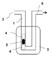
- FIG. 4 is an explanatory diagram of a measuring device when measuring the amounts of CO and CO 2 using the TPD method and measuring the amount of edges using the TPO method.
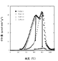
- 5 is a graph showing the relationship between the temperature and the amount of CO in carbons A1 to A4.
- 5 is a graph showing the relationship between the temperature and the amount of CO 2 in carbons A1 to A4.
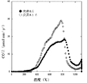
- 4 is a graph showing the relationship between the temperature and the amount of CO in carbon A1 and carbons A5 to A7.
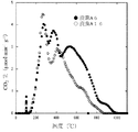
- 4 is a graph showing the relationship between the temperature and the amount of CO 2 at carbon A1 and carbons A5 to A7.
- the graph which shows the relationship between temperature and carbon content in carbon A6 and A16. Graph showing the relationship between the temperature and the amount of CO 2 in the carbon A6, A16.
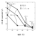
- 4 is a graph showing the amount of functional groups and BET specific surface area in A1 to A4.
- 4 is a graph showing a relationship between a temperature and a CO amount.
- 5 is a graph showing the relationship between temperature and CO 2 amount.
- 4 is a graph showing a relationship between a heat treatment temperature and a CO amount.
- 5 is a graph showing the relationship between the heat treatment temperature and the amount of CO 2 .
- the present invention provides a first step of firing a material containing a carbon source and a template source to produce a carbonaceous fired body, and immersing the carbonaceous fired body in a template removing solution to form the carbonaceous fired body.
- a step of removing the template from the, the method of manufacturing a porous carbon comprising, the type of the material, the ratio of the carbon source and the template source, the template size, and By changing at least two or more conditions among the conditions of the type of the template removing solution, the type of the functional group present in the porous carbon, the amount of the functional group, or the ratio of the functional group is regulated. I do.
- the pore structure (a structure having a large number of mesopores, and a micropore is formed at a position facing the mesopores in the carbonaceous wall constituting the outer periphery of the mesopores.
- the mesopores are open pores, and the structure in which the pore portions are continuous can be changed, and the type of the functional group, the amount of the functional group, or the ratio of the functional group can be changed while suppressing the change. .
- the amount of the functional group and the like can be changed without heat treatment, the production cost of the porous carbon can be reduced.
- the type of the functional group and the like can be changed under conditions such as the mixing ratio of the carbon source and the template source.
- the degree of freedom of the production is increased. improves.
- the condition of the mixing ratio of the carbon source and the template source and the type of the organic resin is selected to produce porous carbon, the ratio of the carbon source in the mixing ratio of the carbon source and the template source is reduced, and the template is removed.
- the ratio of the template source is reduced in the mixing ratio of the carbon source and the template source, and even when sulfuric acid is used as the template removal solution, the types of the functional groups are the same. can do.
- the template refers to a carbonaceous fired body produced by firing a material including a carbon source and a material serving as a template source, which can be removed by a template removing solution.
- the template source is the above-mentioned template, and a part thereof becomes a template by baking like a metal organic acid, or a part of the resin disappears by baking to become a template.
- a mold itself such as a metal oxide.
- the template size is the size of the template and refers to the crystallite diameter calculated by the Scherrer equation from the peak half width of the data obtained by X-ray diffraction measurement.
- the material containing the carbon source and the template source is a mixture of a metal organic acid or an organic resin and a template.
- those having a pore diameter of less than 2 nm are called micropores
- those having a pore diameter of 2 nm to 50 nm are called mesopores
- those having a pore diameter of more than 50 nm are called macropores.
- the present invention provides a first step of firing a material containing a carbon source and a template source to produce a carbonaceous fired body, and immersing the carbonaceous fired body in a template removing solution to form the carbonaceous fired body.
- a method for producing porous carbon comprising: a second step of removing a mold from a mold; and a third step of heat-treating the mold after removing the mold, wherein the type of the material and the carbon source are By changing at least two or more of the ratio of the template source, the template size, the type of the template removal solution, and the temperature or time of the heat treatment, the ratio is present in the porous carbon. It is characterized in that the type of the functional group, the amount of the functional group, or the ratio of the functional group is regulated.
- the degree of freedom in manufacturing porous carbon is also improved. If the temperature during the heat treatment exceeds 1000 ° C., the structure of the porous carbon may change because the porous carbon may be graphitized. Therefore, the temperature at the time of the heat treatment is desirably 1000 degrees or less.
- the present invention provides a first step of firing a mixture of a metal organic acid or an organic resin and a template to produce a carbonaceous fired body, and immersing the carbonaceous fired body in a template removal solution.
- a method for producing porous carbon comprising: a second step of removing a mold from the carbonaceous fired body; and a third step of heat-treating the mold after removal of the mold, wherein the organic resin and the mold are By changing at least two or more of the mixing ratio, the template size, the type of the template removal solution, and the temperature or time of the heat treatment, the type of the functional group present in the porous carbon, It is also possible to regulate the amount of groups or the ratio of functional groups. Even with such a configuration, the same operation and effect as described above can be exerted.
- the type of the functional group, the amount of the functional group, or the ratio of the functional group is regulated, and the micropore volume is reduced. It is characterized by being at least 0.2 ml / g.
- the micropore volume is preferably at least 0.25 ml / g, more preferably at least 0.3 ml / g, particularly preferably at least 0.35 ml / g.
- the present invention provides a first step of firing a material containing a carbon source and a template source to produce a carbonaceous fired body, and immersing the carbonaceous fired body in a template removal solution to form the carbonaceous fired body.
- a second step of removing the template from the fired body comprising: changing the template size to change the type of the functional group and the amount of the functional group present in the porous carbon. Or regulating the ratio of the functional groups.
- the present invention provides a first step of firing a mixture of a metal organic acid or an organic resin and a template to produce a carbonaceous fired body, and immersing the carbonaceous fired body in a template removal solution.
- the present invention provides a first step of firing a material containing a carbon source and a template source to produce a carbonaceous fired body, and immersing the carbonaceous fired body in a template removal solution to form the carbonaceous fired body.
- a method for producing porous carbon comprising: a second step of removing a mold from a fired body; and a third step of heat-treating the mold after removal of the mold. It is characterized in that the type of functional group, the amount of the functional group, or the ratio of the functional group present in the carbon is regulated.
- the present invention provides a first step of firing a mixture of a metal organic acid or an organic resin and a template to produce a carbonaceous fired body, and immersing the carbonaceous fired body in a template removal solution.
- a method for producing porous carbon comprising: a second step of removing a mold from the carbonaceous fired body; and a third step of heat-treating the mold after removing the mold, wherein the size of the mold is changed.
- the type of the functional group, the amount of the functional group, or the ratio of the functional group present in the porous carbon is regulated.
- the edge amount can be changed only by changing the mold size. By changing the edge amount, the type of the functional group, the amount of the functional group, or the ratio of the functional group can be changed. Can be. As a result, porous carbon having different types of functional groups and the like can be easily produced.
- porous carbon produced by the above production method is used as an electrode or a catalyst carrier.
- the porous carbon produced by the production method of the present invention is not limited to these uses, and can be used as an adsorbent or the like.
- examples of the metal organic acid include magnesium citrate, magnesium oxalate, calcium citrate, calcium oxalate and the like.
- the metal organic acid may be a hydrate or an anhydride.
- examples of the template include oxides of alkaline earth metals.
- examples of the alkaline earth metal include magnesium, calcium, strontium, barium and the like. Of these, magnesium and calcium are preferred, and magnesium is most preferred.
- thermosetting resins can be used, specifically, polyvinyl alcohol, aliphatic or aromatic polyester resin, polyolefin resin, Acrylic resins, styrene resins, polyamide resins, polyacrylonitrile resins, various synthetic resins and polymers such as elastomers mainly composed of polybutadiene and polyisoprene, as well as thermoplastic resins and polymers such as natural rubber and petroleum resins, Alternatively, a thermosetting resin such as a phenol resin, a furan resin, an epoxy resin, and an alkyd resin is used.
- a cleaning solution (template removing solution) for removing the template a common inorganic acid such as hydrochloric acid, sulfuric acid, nitric acid, and acetic acid is used, and it is preferable to use a dilute acid of 2 mol / l or less. It is also possible to use hot water of 80 ° C. or higher.
- Example 1 trimagnesium dicitrate [Mg 3 (C 6 H 5 O 7 ) 2 ] serving as a carbon source and a template source was prepared, and baked at 900 ° C. for 1 hour in a nitrogen gas atmosphere. As a result, a fired product having MgO as a mold and a carbonaceous wall was obtained. Next, the obtained fired product was washed with a sulfuric acid solution added at a rate of 1 mol / l to completely elute MgO, thereby obtaining porous carbon having many mesopores and micropores.
- the porous carbon produced in this manner is hereinafter referred to as carbon A1.
- Example 2 The carbon A1 was heat-treated at 400 ° C. for 1 hour in a nitrogen gas atmosphere.
- the porous carbon thus produced is hereinafter referred to as carbon A2.
- Example 3 The carbon A1 was heat-treated at 700 ° C. for 1 hour in a nitrogen gas atmosphere.
- the porous carbon produced in this manner is hereinafter referred to as carbon A3.
- Example 4 The carbon A1 was heat-treated at 1000 ° C. for 1 hour in a nitrogen gas atmosphere.
- the porous carbon thus produced is hereinafter referred to as carbon A4.
- Example 5 A mixture of PVA (polyvinyl alcohol) as a carbon source and MgO particles having a template size of 10 nm at a weight ratio of 5: 5 was fired under the same conditions as in Example 1 to elute MgO.
- the porous carbon thus produced is hereinafter referred to as carbon A5.
- Example 6 A porous carbon was produced in the same manner as in Example 5 except that the MgO particles having a template size of 30 nm were used.
- the porous carbon produced in this manner is hereinafter referred to as carbon A6.
- Example 7 A porous carbon was produced in the same manner as in Example 5, except that the MgO particles having a template size of 150 nm were used.
- the porous carbon thus produced is hereinafter referred to as carbon A7.
- Example 8 The carbon A5 was heat-treated at 700 ° C. for 1 hour in a nitrogen gas atmosphere.
- the porous carbon thus produced is hereinafter referred to as carbon A8.
- Example 9 The carbon A5 was heat-treated at 400 ° C. for 1 hour in a nitrogen gas atmosphere.
- the porous carbon thus produced is hereinafter referred to as carbon A9.
- Example 10 The carbon A5 was heat-treated at 1000 ° C. for 1 hour in a nitrogen gas atmosphere.
- the porous carbon thus produced is hereinafter referred to as carbon A10.
- Example 11 A porous carbon was produced in the same manner as in Example 5 except that hydrochloric acid was used as a cleaning solution (template removing solution).
- the porous carbon produced in this manner is hereinafter referred to as carbon A11.
- Example 12 A porous carbon was produced in the same manner as in Example 5 except that nitric acid was used as the cleaning liquid.
- the porous carbon thus produced is hereinafter referred to as carbon A12.
- Example 13 Porous carbon was produced in the same manner as in Example 5 except that PVA and MgO particles were mixed at a weight ratio of 3: 7. The porous carbon thus produced is hereinafter referred to as carbon A13.
- Example 14 Porous carbon was produced in the same manner as in Example 5 except that a phenol resin was used as a carbon source and the phenol resin and MgO particles were mixed at a weight ratio of 3: 7. The porous carbon thus produced is hereinafter referred to as carbon A14.
- Example 15 Porous carbon was produced in the same manner as in Example 5 except that a phenol resin was used as a carbon source, and the phenol resin and MgO particles were mixed at a weight ratio of 4: 6. The porous carbon thus produced is hereinafter referred to as carbon A15.
- Example 16 Porous carbon was produced in the same manner as in Example 5 except that a phenol resin was used as a carbon source and MgO particles having a template size of 30 nm were used.
- the porous carbon produced in this manner is hereinafter referred to as carbon A16.
- the relative pressure (P / P 0) is calculated from the adsorption amount of 0.95.
- -Micropore volume Calculated using the DA (Dubinin-Astakhov) method.
- -Mesopore volume The mesopore volume was calculated by subtracting the micropore volume from the total pore volume.
- ⁇ CO amount using the device of the CO 2 amount Figure 1, was measured using a TPD (Temperature Programmed Desorption) method. Specifically, it is as follows. First, a sample 3 (sample amount: 100 mg) is placed between the glass wools 4 and 4 in the pipeline 1 shown in FIG. Next, the temperature is raised from room temperature to 100 ° C. at a rate of 10 ° C./min while supplying He gas (flow rate 15 ⁇ 10 ⁇ 3 dm 3 / min) from the gas supply port 2. Next, after maintaining at 100 ° C. for 1 hour, the temperature is increased from 100 ° C. to 1100 ° C. at a rate of 5 ° C./min while supplying He gas from the gas supply port 2.
- TPD Temporal Programmed Desorption
- the average particle size (D 50 ) is the particle size at which the cumulative volume becomes 50%, and the particle size distribution is measured by a laser scattering method using a particle size / particle size distribution measuring device (LA-950, Horiba, Ltd.). I asked.
- carbon A2 heat-treated at 400 ° C. has a large drop at a peak near 300 ° C. as compared with carbon A1 not heat-treated, and carbon A3 heat-treated at 700 ° C. heat-treated at 400 ° C.
- the peak is significantly reduced at around 400 ° C.
- the carbon A4 heat-treated at 1000 ° C. has a large drop overall as compared with the carbon A3 heat-treated at 700 ° C.
- the particle size is to compare different carbon A1, A5 ⁇ A7, generally recognized that particle size larger the amount of CO and CO 2 content is low
- FIGS. 6 and 7 it is compared with the carbon A16 with phenol resin as a carbon A6 and carbon source using PVA as a carbon source, CO amount slightly more carbon A16, CO 2 amount It is recognized that carbon A6 is slightly increased.
- micropore volumes are substantially the same.
- carbons A6 and A16 with different carbon sources it is recognized that the micropore volumes are substantially the same.
- the micropore volume was slightly increased by increasing the blending ratio of the template source, but no significant change was observed. The same tendency was also observed when comparing carbons A14 and A15 having different mixing ratios between the carbon source and the template source.
- Example 2 BET specific surface area of carbons A1 to A8, A11 to A16, measured CO amount, acid anhydride amount, total amount of ether group and hydroxyl group, total amount of quinone and carbonyl group, amount at peak near 1000 ° C., measured CO 2 amount,
- the amounts of carboxyl groups, lactones, measured CO amount + CO 2 amount, H 2 terminal amount, and edge amount were examined by the following methods, and the results are shown in Tables 3 and 4. Incidentally, the amount at the peak of around 1000 ° C. is not observed a peak at a carbon A1 ⁇ A4 and A12, also, the edge amount is determined only carbon A1, A5 ⁇ A7, the H 2 termination amount, carbon A1 , A5 to A7 only.
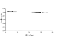
- FIG. 14 shows the relationship between the mold size and the edge amount
- FIG. 15 shows the relationship between the edge amount and the functional group amount (actual measured CO amount and measured CO 2 amount).
- FIG. 16 shows the amounts of functional groups in carbons A1 and A5 to A7
- FIG. 17 shows the amounts of functional groups and BET specific surface areas in carbons A1 to A4.
- Fig. 18 is a graph showing the relationship between the temperature and the CO amount of carbon A1 obtained by the measurement in the above experiment 1.
- Curve 10 (connecting ⁇ ) is the amount of CO released at each temperature, and the area enclosed by curve 10 and the horizontal axis (the area indicated by the dots in FIG. 18) is the total amount of released CO. And the actual measured CO amount.
- the amount of CO released and released from the acid anhydride becomes maximum at around 600 ° C., the maximum is about 800 ° C.
- the waveform separation is performed from the curve 10 into a curve 11 (amount of acid anhydride), a curve 12 (amount of ether group and hydroxyl group), and a curve 13 (amount of quinone and carbonyl group).
- the area enclosed by the curve 11 and the horizontal axis is the total amount of the acid anhydride discharged, and the area enclosed by the curve 12 and the horizontal axis (FIG.
- FIG. 19 is a graph showing the relationship between the temperature and the amount of CO 2 in the carbon A1 obtained by the measurement in the experiment 1 above.
- the calculation method is based on FIG. Is shown.
- Curve 21 (connecting ⁇ ) is the amount of CO 2 released at each temperature, and the area enclosed by curve 21 and the horizontal axis (the area indicated by the dots in FIG. 19) is the amount of released CO 2 . This is the total amount, which is the measured CO 2 amount.
- the amount of carboxyl group released and CO 2 discharged becomes maximum at around 250 ° C.
- that of lactone becomes maximum at around 400 ° C.
- acid anhydride becomes maximum at around 600 ° C.
- the waveform is separated from the curve 21 into a curve 22 (amount of carboxyl group), a curve 23 (amount of lactone), and a curve 24 (amount of acid anhydride).
- the area surrounded by the curve 22 and the horizontal axis (the area indicated by hatching in the upward right direction in FIG. 19) is the amount of the discharged carboxyl groups, and the area surrounded by the curve 23 and the horizontal axis (the area shown in FIG. 19)
- the area indicated by hatching in the lower right direction) is the amount of discharged lactone, and the area enclosed by the curve 24 and the horizontal axis (the area indicated by vertical hatching in FIG. 19) is the total amount of acid anhydride discharged.
- the amount of acid anhydride obtained from the measured amount of CO 2 because very small compared to the amount of acid anhydride obtained from the measured amount of CO, in the present specification, the acid anhydride obtained from the measured amount of CO The amount is defined as the amount of the acid anhydride.
- the respective amounts of carbons A2 to A8 were determined.
- the edge amount was measured by the TPO (Temperature Programmed Oxidation) method using the apparatus shown in FIG. Specifically, it is as follows. First, a sample 3 (sample amount: 100 mg) is placed between the glass wools 4 and 4 in the pipeline 1 shown in FIG. Next, the temperature is raised from room temperature to 800 ° C. at a rate of 20 ° C./min while supplying He gas (flow rate 200 ⁇ 10 ⁇ 3 dm 3 / min) from the gas supply port 2.
- TPO Temporal Programmed Oxidation
- He gas flow rate 180 ⁇ 10 ⁇ 3 dm 3 / min
- O 2 gas flow rate 20 ⁇ 10 ⁇ 3 dm 3 / min
- the temperature was raised from 800 ° C. to 1000 ° C., it was kept at 1000 ° C. for 2 hours.
- the amount of dewatering and dewatering in the gas discharged from the gas discharge port 6 was examined, and the edge amount was calculated from the amount of dewatering and dewatering.
- the measurement of the amount of separation and dehydration used the Karl Fischer moisture meter (MKC-610 of Kyoto Electronics Industry Co., Ltd.).
- the edge portion refers to a portion that exists on the carbon surface and can be terminated with a functional group.
- the edge amount refers to the amount (mmol / g) of the edge portion present in 1 g.
- ⁇ H 2 termination weight H 2 termination amount from the edge amount was calculated by subtracting all the amount of functional groups.
- the amount of all the functional groups means the amount of the acid anhydride, the total amount of the ether group and the hydroxyl group, the total amount of the quinone and the carbonyl group, the amount of the carboxyl group, and the amount of the lactone in Tables 3 and 4. It means the amount obtained by adding the amount.
- the size of the template was changed, the raw material was changed, or a metal organic acid (such as trimagnesium dicitrate) was used, or an organic resin (such as PVA) and a template (MgO particles) were used.
- a metal organic acid such as trimagnesium dicitrate
- an organic resin such as PVA
- a template MgO particles
- the edge amount decreases as the mold size increases, and as is clear from FIG. 15, when the edge amount decreases, the functional group amounts (actually measured CO amount, measured CO 2 amount) are reduced. Decrease. Therefore, the amount of the functional group is decreased by increasing the template size, and the amount of the functional group is increased by decreasing the template size. Therefore, by changing the template size, the amount of the functional group (actual measured CO amount, measured CO 2 amount) ) Can be adjusted to the desired amount.
- carbon A1 has the maximum amount of functional groups, and in all of carbon A1, A5 to A7, many acid anhydrides were observed among the five functional groups. In addition, it was found that the amount of the functional group decreased as the pore diameter increased. In consideration of the above, it is not clear, but it is possible that the number of edges of the functional group is increased due to an increase in the number of locations where the mesopores communicate with each other due to a decrease in the pore diameter.
- the micropore volume is large and the amount of the functional group is small. This is because the larger the micropore capacity, the larger the specific surface area, and the larger the specific surface area, the larger the battery capacity. Also, when the amount of the functional group is small, generation of gas during use of the battery is suppressed, and deterioration of the battery can be suppressed.
- the template size it is necessary to reduce the template size. However, when the template size is reduced, there is a problem that the amount of the functional group increases. However, by performing the heat treatment, it is possible to suppress the decrease in the micropore volume while reducing the amount of the functional group.
- the micropore volume is preferably 0.2 ml / g or more, and the specific surface area is preferably 500 m 2 / g or more. Therefore, among the carbons A1 to A16, carbon A4 having a small template size and a small amount of functional groups (porous carbon heat-treated at 1000 ° C. using magnesium citrate serving also as a carbon source and a template source, It is preferable to use porous carbon having a micropore volume of 0.2 ml / g or more and a specific surface area of 500 m 2 / g or more. In the case of magnesium citrate, there is an advantage that the number of manufacturing steps can be reduced since there is no need to mix, leading to cost reduction.
- a catalyst carrier When used as a catalyst carrier, it is preferable to have a high specific surface area and to have a communicating hole composed of mesopores derived from a template. If the specific surface area is high, the catalyst particles become finer, and the surface area of the catalyst increases. For this reason, the activity per mass of the catalyst is increased.
- having a communication hole composed of a mesopore derived from a template has high gas diffusivity and facilitates the movement of a substance, so that the catalytic reaction proceeds efficiently and the catalytic activity is improved.
- the specific surface area is preferably at least 500 m 2 / g, more preferably at least 700 m 2 / g, even more preferably at least 800 m 2 / g and at most 1200 m 2 / g.
- durability and conductivity may be emphasized or the amount of functional groups may be emphasized.
- heat treatment (900 ° C. or higher) It is preferable to perform heat treatment at 900 ° C. or more to improve crystallinity, improve durability and conductivity, and perform a heat treatment at a temperature of 900 ° C. or higher, such as magnesium citrate serving as a carbon source and a template source, or PVA. It is preferable to use porous carbon which is heat-treated at 1000 ° C.
- a heat treatment using a magnesium citrate serving as a carbon source and a template source, or a carbon source such as PVA and a template source (a template size of 3 to 30 nm) such as a metal oxide is performed. It is better not to carry out, or to carry out at 800 ° C. or lower.
- a magnesium citrate having a template size close to the catalyst size is used.
- heat-treated (preferably 900 ° C. or higher) porous carbon is used, and in this embodiment, carbon A4 is preferably used.
- the pore size of the mesopores needs to be 10 nm or more, and is preferably 30 nm or more.
- the amount of functional groups) of the enzyme it becomes difficult to fix the enzyme to the carrier.
- the amount of the functional group can be increased by changing the ratio of the cleaning liquid, the carbon source and the template, and the like.
- the size of the template is 30 to 150 nm, and that the ratio between the carbon source and the template is porous carbon prepared by increasing the ratio of the template.
- the present invention is an adsorbent, a catalyst carrier such as a fuel cell and a catalyst for organic synthesis, an enzyme electrode such as a biosensor, an immobilized enzyme carrier, and a metal hydrogen battery, an air battery, a LiS battery, a NaS battery, and a lithium ion battery. And active materials and auxiliaries in electrodes in batteries such as lead-acid batteries.
Landscapes
- Chemical & Material Sciences (AREA)
- Organic Chemistry (AREA)
- Chemical Kinetics & Catalysis (AREA)
- Engineering & Computer Science (AREA)
- Materials Engineering (AREA)
- Inorganic Chemistry (AREA)
- Analytical Chemistry (AREA)
- General Chemical & Material Sciences (AREA)
- Electrochemistry (AREA)
- Nanotechnology (AREA)
- Physics & Mathematics (AREA)
- Thermal Sciences (AREA)
- Carbon And Carbon Compounds (AREA)
- Inert Electrodes (AREA)
- Catalysts (AREA)
- Battery Electrode And Active Subsutance (AREA)
- Solid-Sorbent Or Filter-Aiding Compositions (AREA)
- Electric Double-Layer Capacitors Or The Like (AREA)
Abstract
Description
また、鋳型源とは上記鋳型となるもので、金属有機酸のように焼成することによりその一部が鋳型となるものや、焼成することによりその一部の樹脂が消失して鋳型となるもの、及び金属酸化物等のように鋳型そのものをいう。
更に、鋳型サイズとは上記鋳型の大きさであり、X線回折測定により得られたデータのピーク半値幅からシェラー式により算出した結晶子径をいう。
また、炭素源と鋳型源となるものを含む材料とは、金属有機酸、又は有機質樹脂と鋳型とを混合したものをいう。
また、本明細書においては、細孔径が2nm未満のものをミクロ孔、細孔径が2nm~50nmのものをメソ孔、細孔径が50nmを超えるものをマクロ孔と称することとする。
このような構成であっても、上記と同様の作用効果を発揮できる。尚、有機質樹脂の種類等を変更することでも、官能基の種類、官能基の量、又は官能基の比率を調整ができる
尚、熱処理時の温度が1000℃を超えると、多孔質炭素が黒鉛化することがあるため、多孔質炭素の構造が変化しうる。したがって、上記熱処理時の温度は1000度以下であることが望ましい。
このような構成であっても、上記と同様の作用効果を発揮できる。
上述のごとく、本発明の製造方法によれば、上記ミクロ孔容量の変化を抑制しつつ、官能基の種類、官能基の量、又は官能基の比率を所望の値に規制することが可能となる。
なお、ミクロ孔容量は0.25ml/g以上であることが好ましく、0.3ml/g以上であることがより好ましく、特に、0.35ml/g以上であることが一層好ましい。
上述した4つの構成のように、鋳型サイズを変更するだけで、エッジ量を変えることができ、このエッジ量が変わることにより官能基の種類、官能基の量、又は官能基の比率を変えることができる。この結果、官能基の種類等が異なる多孔質炭素を容易に製造することができる。
但し、本発明の製造方法により製造された多孔質炭素は、これらの用途に限定するものではなく、吸着剤等に用いることもできる。
上記鋳型としては、アルカリ土類金属の酸化物等が挙げられる。アルカリ土類金属としてはマグネシウム、カルシウム、ストロンチウム、バリウム等が挙げられるが、これらの中でも好ましいのはマグネシウムとカルシウムであり、とりわけマグネシウムが最適である。
先ず、炭素源と鋳型源とを兼ねる二クエン酸三マグネシウム〔Mg3(C6H5O7)2〕を用意し、これを窒素ガス雰囲気中900℃で1時間焼成した。これにより、鋳型であるMgOと炭素質壁とを備えた焼成物を得た。次いで、得られた焼成物を1mol/lの割合で添加された硫酸溶液で洗浄して、MgOを完全に溶出させることにより、多数のメソ孔とミクロ孔とを有する多孔質炭素を得た。
このようにして作製した多孔質炭素を、以下、炭素A1と称する。
上記炭素A1を窒素ガス雰囲気下、400℃で1時間熱処理した。
このようにして作製した多孔質炭素を、以下、炭素A2と称する。
上記炭素A1を窒素ガス雰囲気下、700℃で1時間熱処理した。
このようにして作製した多孔質炭素を、以下、炭素A3と称する。
上記炭素A1を窒素ガス雰囲気下、1000℃で1時間熱処理した。
このようにして作製した多孔質炭素を、以下、炭素A4と称する。
炭素源としてのPVA(ポリビニルアルコール)と、鋳型サイズ10nmのMgO粒子とを5:5の重量比で混合したものを、上記実施例1と同様の条件で焼成、MgOの溶出を行った。
このようにして作製した多孔質炭素を、以下、炭素A5と称する。
MgO粒子として、鋳型サイズが30nmのものを用いた他は、上記実施例5と同様にして多孔質炭素を作製した。
このようにして作製した多孔質炭素を、以下、炭素A6と称する。
MgO粒子として、鋳型サイズが150nmのものを用いた他は、上記実施例5と同様にして多孔質炭素を作製した。
このようにして作製した多孔質炭素を、以下、炭素A7と称する。
上記炭素A5を窒素ガス雰囲気下、700℃で1時間熱処理した。
このようにして作製した多孔質炭素を、以下、炭素A8と称する。
上記炭素A5を窒素ガス雰囲気下、400℃で1時間熱処理した。
このようにして作製した多孔質炭素を、以下、炭素A9と称する。
上記炭素A5を窒素ガス雰囲気下、1000℃で1時間熱処理した。
このようにして作製した多孔質炭素を、以下、炭素A10と称する。
洗浄液(鋳型除去溶液)として塩酸を用いた他は、上記実施例5と同様にして多孔質炭素を作製した。
このようにして作製した多孔質炭素を、以下、炭素A11と称する。
洗浄液として硝酸を用いた他は、上記実施例5と同様にして多孔質炭素を作製した。
このようにして作製した多孔質炭素を、以下、炭素A12と称する。
PVAとMgO粒子とを3:7の重量比で混合した他は、上記実施例5と同様にして多孔質炭素を作製した。
このようにして作製した多孔質炭素を、以下、炭素A13と称する。
炭素源としてフェノール樹脂を用い、且つこのフェノール樹脂とMgO粒子とを3:7の重量比で混合した他は、上記実施例5と同様にして多孔質炭素を作製した。
このようにして作製した多孔質炭素を、以下、炭素A14と称する。
炭素源としてフェノール樹脂を用い、且つこのフェノール樹脂とMgO粒子とを4:6の重量比で混合した他は、上記実施例5と同様にして多孔質炭素を作製した。
このようにして作製した多孔質炭素を、以下、炭素A15と称する。
炭素源としてフェノール樹脂を用い、且つ鋳型サイズが30nmのMgO粒子を用いた他は、上記実施例5と同様にして多孔質炭素を作製した。
このようにして作製した多孔質炭素を、以下、炭素A16と称する。
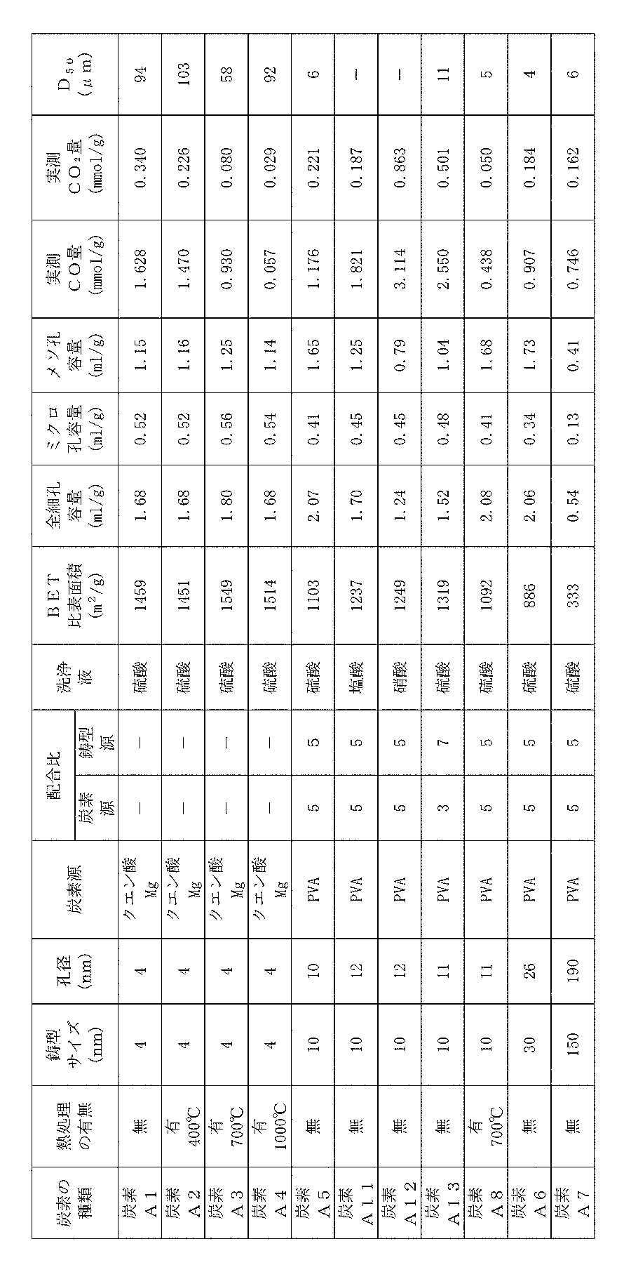
炭素A1~A16の孔径、BET比表面積、全細孔容量、ミクロ孔容量、メソ孔容量、炭素A1~A8、A11~A16のCO量、CO2量、及び炭素A1~A8、A13~A16の平均粒子径(D50)について、下記の方法で調べたので、それらの結果を表1及び表2に示す。なお、炭素A1~A16は、メソ孔の外殻を構成する炭素質壁におけるメソ孔に臨む位置にはミクロ孔が形成され、また、上記メソ孔は開気孔であって、気孔部分が連続するような構造であった。
窒素ガスによる77Kでの吸着等温線からBJH(Berret-Joyner-Halenda)法を用いて算出した。但し、炭素A7では、SEMより細孔の孔径を確認した。
・ BET比表面積
各試料に、窒素ガスを77Kの温度中の各相対圧力で吸着させ、吸着等温線を測定し、BET法によって算出した。
窒素ガスによる77Kでの吸着等温線において、相対圧(P/P0)が0.95における吸着量から算出した。
・ ミクロ孔容量
DA(Dubinin-Astakhov)法を用いて算出した。
・メソ孔容量
全細孔容量からミクロ孔容量を差し引くことでメソ孔容量を算出した。
図1の装置を用いて、TPD(Temperature Programmed Desorption)法を用いて測定した。具体的には、以下の通りである。
先ず、図1に示す管路1内のグラスウール4,4間にサンプル3(サンプル量は100mg)を配置する。次に、ガス供給口2からHeガス(流量15×10-3dm3/min)を供給しつつ、10℃/分の速度で室温から100℃になるまで昇温する。次いで、100℃で1時間保持した後、ガス供給口2からHeガスを供給しつつ、5℃/分の速度で100℃から1100℃になるまで昇温する。そして、1100℃で2時間保持した。これら一連の昇温過程で、ガス排出口6から排出されるガス中のCO量とCO2量とを調べた。尚、CO量とCO2量との測定は、ガスクロマトグラフ(ジーエルサイエンス株式会社のVarian490-GC)を用いた。また、図1における5は加熱炉である。なお、このような測定によって、各温度で放出されたCO量およびCO2量の値が得られる。
平均粒子径(D50)とは、累積体積が50%となる粒子径であり、粒子径・粒度分布測定装置(株式会社堀場製作所LA-950)を用いたレーザー散乱法により粒度分布を測定して求めた。

更に、図6及び図7から明らかように、炭素源としてPVAを用いた炭素A6と炭素源としてフェノール樹脂を用いた炭素A16とを比較すると、CO量は炭素A16が若干多く、CO2量は炭素A6が若干多くなっていることが認められる。
また、図10及び図11から明らかように、共に炭素源としてフェノール樹脂を用い、鋳型比率の異なる炭素A14と炭素A15とを比較すると、鋳型比率の高い炭素A14の方がCO量とCO2量が多くなっていることが認められる。
また、炭素源と鋳型源との配合比が異なる炭素A5、A13を比較した場合、鋳型源の配合比が増加することでミクロ孔容量はやや増加するものの、大きな変化は認められなかった。また、炭素源と鋳型源との配合比が異なる炭素A14、A15を比較した場合も、同様の傾向となった。
これらのことから、ミクロ孔容量を変化させたい場合には鋳型サイズを変化させ、ミクロ孔容量を変化させたくない場合にはその他の条件を変化させれば良いことが認められる。
炭素A1~A8、A11~A16のBET比表面積、実測CO量、酸無水物量、エーテル基及び水酸基の合計量、キノン及びカルボニル基の合計量、1000℃付近のピークにおける量、実測CO2量、カルボキシル基の量、ラクトンの量、実測CO量+CO2量、H2終端量、及びエッジ量について、下記の方法で調べたので、それらの結果を表3及び表4に示す。尚、1000℃付近のピークにおける量は炭素A1~A4及びA12ではピークは観測されず、また、エッジ量については、炭素A1、A5~A7についてのみ測定し、H2終端量については、炭素A1、A5~A7についてのみ算出した。
上記実験1と同様にして計測した
図18は炭素A1における、上記実験1の計測で得られた温度とCO量との関係を示すグラフであるが、この図18に基づいて、算出方法を示す。
曲線10(〇をつなぎ合わせたもの)は各温度で放出されたCO量であり、曲線10と横軸とに囲まれた領域(図18の点々で示す領域)が放出されたCO量の総量であり、実測CO量となる。次に、酸無水物では離脱してCOを排出する量が600℃付近で最大となり、エーテル基及び水酸基では800℃付近で最大となり、キノン及びカルボニル基は900℃付近で最大となることが知られている。このことから、曲線10から、曲線11(酸無水物の量)、曲線12(エーテル基及び水酸基の量)、及び曲線13(キノン及びカルボニル基の量)に波形分離を行う。そして、曲線11と横軸とに囲まれた領域(図18の右上がりのハッチングで示す領域)が排出された酸無水物の合計量となり、曲線12と横軸とに囲まれた領域(図18の右下がりのハッチングで示す領域)が排出されたエーテル基及び水酸基の合計量となり、曲線13と横軸とに囲まれた領域(図18の縦方向のハッチングで示す領域)が排出されたキノン及びカルボニル基の合計量となる。
同様の方法で、炭素A2~A8についても各量を求めた
図19は炭素A1における、上記実験1の計測で得られた温度とCO2量との関係を示すグラフであるが、この図19に基づいて、算出方法を示す。
曲線21(〇をつなぎ合わせたもの)は各温度で放出されたCO2量であり、曲線21と横軸とに囲まれた領域(図19の点々で示す領域)が放出されたCO2の総量であり、実測CO2量となる。次に、カルボキシル基は離脱してCO2を排出する量が250℃付近で最大となり、ラクトンでは400℃付近で最大となり、酸無水物は600℃付近で最大となることが知られている。このことから、曲線21から、曲線22(カルボキシル基の量)、曲線23(ラクトンの量)、及び曲線24(酸無水物の量)に波形分離を行う。そして、曲線22と横軸とに囲まれた領域(図19の右上がりのハッチングで示す領域)が排出されたカルボキシル基の量となり、曲線23と横軸とに囲まれた領域(図19の右下がりのハッチングで示す領域)が排出されたラクトンの量となり、曲線24と横軸とに囲まれた領域(図19の縦方向のハッチングで示す領域)が排出された酸無水物の総量となる。尚、実測CO2量から得られる酸無水物の量は、上記実測CO量から得られる酸無水物の量に比べて極めて少ないので、本明細書では、実測CO量から得られる酸無水物の量を酸無水物の量と規定する。
同様の方法で、炭素A2~A8についても各量を求めた
図1の装置を用いて、TPO(Temperature Programmed Oxidation)法で測定した。具体的には、以下の通りである。
先ず、図1に示す管路1内のグラスウール4,4間にサンプル3(サンプル量は100mg)を配置する。次に、ガス供給口2からHeガス(流量200×10-3dm3/min)を供給しつつ、20℃/分の速度で室温から800℃になるまで昇温する。次いで、ガス供給口2からHeガス(流量180×10-3dm3/min)とO2ガス(流量20×10-3dm3/min)とを供給しつつ、5℃/分の速度で800℃から1000℃になるまで昇温した後、1000℃で2時間保持した。そして、このときにガス排出口6から排出されるガス中の離脱水分量を調べ、この離脱水分量からエッジ量を算出した。尚、離脱水分量の測定は、カールフィッシャー水分計(京都電子工業株式会社のMKC-610)を用いた。
なお、本願においてエッジ部とは炭素表面上に存在し、官能基で終端されうる部位を言う。またエッジ量とは、1g中に存在するエッジ部の量(mmol/g)を言う。
H2終端量は、エッジ量から、全ての官能基量を減算することにより算出した。尚、全ての官能基量とは、表3及び表4における、酸無水物の量と、エーテル基及び水酸基の合計量と、キノン及びカルボニル基の合計量と、カルボキシル基の量と、ラクトンの量とを加算した量をいう。


本発明により製造した多孔質炭素を電極に用いる場合には、ミクロ孔容量は大きく、官能基量は少ない方が好ましい。ミクロ孔容量が大きければ、比表面積が大きくなり、比表面積が大きいと電池容量も大きくなるからである。また、官能基量が少ないと、電池使用時のガス発生が抑えられ、電池の劣化を抑制できるからである。ここで、ミクロ孔容量を大きくするためには鋳型サイズを小さくする必要があるが、鋳型サイズを小さくすると、官能基量は多くなるという問題がある。しかしながら、熱処理することにより、官能基量を減少させつつミクロ孔容量の減少を抑制できる。なお、電極に用いる場合にはミクロ孔容量が0.2ml/g以上、比表面積が500m2/g以上が好ましく、上記のことから熱処理(1000℃以下)することが好ましい。したがって、上記炭素A1~A16の中では、鋳型サイズが小さく且つ官能基量の少ない炭素A4(炭素源と鋳型源とを兼ねるクエン酸マグネシウムを用い、1000℃で熱処理した多孔質炭素であって、ミクロ孔容量が0.2ml/g以上、かつ比表面積が500m2/g以上を満たす多孔質炭素)を用いるのが好ましい。クエン酸マグネシウムの場合、混合する必要がないため、製造工程数を減らすことができ、コストダウンにつながるという利点がある。
2:ガス供給口
3:サンプル
4:グラスウール
5:加熱炉
6:ガス排出口
Claims (10)
- 炭素源と鋳型源となるものを含む材料を焼成して、炭素質焼成体を作製する第1ステップと、上記炭素質焼成体を鋳型除去溶液に浸漬して上記炭素質焼成体から鋳型を除去する第2ステップと、を備えた多孔質炭素の製造方法であって、
上記材料の種類、上記炭素源となるものと上記鋳型源となるものとの比率、上記鋳型サイズ、及び上記鋳型除去溶液の種類という条件のうち少なくとも2以上の条件を変更することにより、多孔質炭素内に存在する官能基の種類、官能基の量、又は官能基の比率を規制することを特徴とする多孔質炭素の製造方法。 - 炭素源と鋳型源となるものを含む材料を焼成して、炭素質焼成体を作製する第1ステップと、上記炭素質焼成体を鋳型除去溶液に浸漬して上記炭素質焼成体から鋳型を除去する第2ステップと、この鋳型を除去したものを、熱処理する第3ステップと、を備えた多孔質炭素の製造方法であって、
上記材料の種類、上記炭素源となるものと上記鋳型源となるものとの比率、上記鋳型サイズ、上記鋳型除去溶液の種類、及び上記熱処理の温度若しくは時間という条件のうち少なくとも2以上の条件を変更することにより、多孔質炭素内に存在する官能基の種類、官能基の量、又は官能基の比率を規制することを特徴とする多孔質炭素の製造方法。 - 炭素源と鋳型源となるものを含む材料を焼成して、炭素質焼成体を作製する第1ステップと、上記炭素質焼成体を鋳型除去溶液に浸漬して上記炭素質焼成体から鋳型を除去する第2ステップとを備え、メソ孔に臨む位置にミクロ孔を形成する、多孔質炭素の製造方法であって、
上記材料の種類、上記炭素源となるものと上記鋳型源となるものとの比率、及び上記鋳型除去溶液の種類という条件のうち少なくとも2以上の条件を変更することにより、官能基の種類、官能基の量、又は官能基の比率を規制し、且つ、上記ミクロ孔容量が0.2ml/g以上となっていることを特徴とする多孔質炭素の製造方法。 - 炭素源と鋳型源となるものを含む材料を焼成して、炭素質焼成体を作製する第1ステップと、上記炭素質焼成体を鋳型除去溶液に浸漬して上記炭素質焼成体から鋳型を除去する第2ステップと、この鋳型を除去したものを、熱処理する第3ステップとを備え、メソ孔に臨む位置にミクロ孔を形成する、多孔質炭素の製造方法であって、
上記材料の種類、上記炭素源となるものと上記鋳型源となるものとの比率、上記鋳型除去溶液の種類、及び上記熱処理の温度若しくは時間という条件のうち少なくとも2以上の条件を変更することにより官能基の種類、官能基の量、又は官能基の比率を規制し、且つ、上記ミクロ孔容量が0.2ml/g以上となっていることを特徴とする多孔質炭素の製造方法。 - 炭素源と鋳型源となるものを含む材料を焼成して、炭素質焼成体を作製する第1ステップと、上記炭素質焼成体を鋳型除去溶液に浸漬して上記炭素質焼成体から鋳型を除去する第2ステップと、を備えた多孔質炭素の製造方法であって、
上記鋳型サイズを変更することにより、多孔質炭素内に存在する官能基の種類、官能基の量、又は官能基の比率を規制することを特徴とする多孔質炭素の製造方法。 - 金属有機酸、又は有機質樹脂と鋳型とを混合したものを焼成して、炭素質焼成体を作製する第1ステップと、上記炭素質焼成体を鋳型除去溶液に浸漬して上記炭素質焼成体から鋳型を除去する第2ステップと、を備えた多孔質炭素の製造方法であって、
上記鋳型サイズを変更することにより、多孔質炭素内に存在する官能基の種類、官能基の量、又は官能基の比率を規制することを特徴とする多孔質炭素の製造方法。 - 炭素源と鋳型源となるものを含む材料を焼成して、炭素質焼成体を作製する第1ステップと、上記炭素質焼成体を鋳型除去溶液に浸漬して上記炭素質焼成体から鋳型を除去する第2ステップと、この鋳型を除去したものを、熱処理する第3ステップと、を備えた多孔質炭素の製造方法であって、
上記鋳型サイズを変更することにより、多孔質炭素内に存在する官能基の種類、官能基の量、又は官能基の比率を規制することを特徴とする多孔質炭素の製造方法。 - 金属有機酸、又は有機質樹脂と鋳型とを混合したものを焼成して、炭素質焼成体を作製する第1ステップと、上記炭素質焼成体を鋳型除去溶液に浸漬して上記炭素質焼成体から鋳型を除去する第2ステップと、この鋳型を除去したものを、熱処理する第3ステップと、を備えた多孔質炭素の製造方法であって、
上記鋳型サイズを変更することにより、多孔質炭素内に存在する官能基の種類、官能基の量、又は官能基の比率を規制することを特徴とする多孔質炭素の製造方法。 - 上記請求項1~請求項8の何れか1項に記載の製造方法により製造された多孔質炭素を含む電極。
- 上記請求項1~請求項8の何れか1項に記載の製造方法により製造された多孔質炭素を含む触媒担体。
Priority Applications (8)
| Application Number | Priority Date | Filing Date | Title |
|---|---|---|---|
| EP24150330.9A EP4331720B1 (en) | 2018-06-29 | 2019-07-01 | Method for producing porous carbon |
| CA3105710A CA3105710A1 (en) | 2018-06-29 | 2019-07-01 | Method of producing porous carbon, and electrode and catalyst carrier containing porous carbon produced by the method |
| EP19826921.9A EP3816105B1 (en) | 2018-06-29 | 2019-07-01 | Method for producing porous carbon |
| CN201980005628.1A CN111344254A (zh) | 2018-06-29 | 2019-07-01 | 多孔碳的制造方法和包含通过该制造方法制造的多孔碳的电极以及催化剂载体 |
| KR1020217002818A KR102566190B1 (ko) | 2018-06-29 | 2019-07-01 | 다공질 탄소의 제조 방법 및 이 제조 방법에 의해 제조된 다공질 탄소를 포함하는 전극 및 촉매 담체 |
| US17/255,768 US11235978B2 (en) | 2018-06-29 | 2019-07-01 | Method of producing porous carbon, and electrode and catalyst carrier containing porous carbon produced by the method |
| JP2019556390A JP6677863B1 (ja) | 2018-06-29 | 2019-07-01 | 多孔質炭素の製造方法及びこの製造方法により製造された多孔質炭素を含む電極及び触媒担体 |
| US17/551,365 US11702344B2 (en) | 2018-06-29 | 2021-12-15 | Method of producing porous carbon, and electrode and catalyst carrier containing porous carbon produced by the method |
Applications Claiming Priority (2)
| Application Number | Priority Date | Filing Date | Title |
|---|---|---|---|
| JP2018125618 | 2018-06-29 | ||
| JP2018-125618 | 2018-06-29 |
Related Child Applications (2)
| Application Number | Title | Priority Date | Filing Date |
|---|---|---|---|
| US17/255,768 A-371-Of-International US11235978B2 (en) | 2018-06-29 | 2019-07-01 | Method of producing porous carbon, and electrode and catalyst carrier containing porous carbon produced by the method |
| US17/551,365 Continuation US11702344B2 (en) | 2018-06-29 | 2021-12-15 | Method of producing porous carbon, and electrode and catalyst carrier containing porous carbon produced by the method |
Publications (1)
| Publication Number | Publication Date |
|---|---|
| WO2020004674A1 true WO2020004674A1 (ja) | 2020-01-02 |
Family
ID=68987285
Family Applications (1)
| Application Number | Title | Priority Date | Filing Date |
|---|---|---|---|
| PCT/JP2019/026199 Ceased WO2020004674A1 (ja) | 2018-06-29 | 2019-07-01 | 多孔質炭素の製造方法及びこの製造方法により製造された多孔質炭素を含む電極及び触媒担体 |
Country Status (7)
| Country | Link |
|---|---|
| US (2) | US11235978B2 (ja) |
| EP (2) | EP4331720B1 (ja) |
| JP (2) | JP6677863B1 (ja) |
| KR (1) | KR102566190B1 (ja) |
| CN (1) | CN111344254A (ja) |
| CA (1) | CA3105710A1 (ja) |
| WO (1) | WO2020004674A1 (ja) |
Cited By (6)
| Publication number | Priority date | Publication date | Assignee | Title |
|---|---|---|---|---|
| JP2023084551A (ja) * | 2021-12-07 | 2023-06-19 | 日本製鉄株式会社 | 鋳型炭素材料の製造方法、触媒の製造方法、固体高分子形燃料電池用触媒層の製造方法、及び燃料電池の製造方法 |
| JP2023530340A (ja) * | 2020-06-16 | 2023-07-14 | ディッキンソン コーポレーション | 無煙炭ネットワーク及び常温超伝導体の合成 |
| US12404176B2 (en) | 2020-09-09 | 2025-09-02 | Dickinson Corporation | Scalable synthesis of perimorphic carbons |
| WO2025225271A1 (ja) * | 2024-04-22 | 2025-10-30 | 日亜化学工業株式会社 | リチウム硫黄電池用多孔質炭素材料及びその製造方法 |
| US12545586B2 (en) | 2017-03-15 | 2026-02-10 | Dickinson Corporation | Composites including unimpregnated cellular carbon nanostructures |
| WO2026083826A1 (ja) * | 2024-10-18 | 2026-04-23 | パナソニックホールディングス株式会社 | ポーラスカーボン、電極材料、触媒担体、キャパシタ、燃料電池、二次電池、およびポーラスカーボンの製造方法 |
Families Citing this family (9)
| Publication number | Priority date | Publication date | Assignee | Title |
|---|---|---|---|---|
| JP7484650B2 (ja) * | 2020-10-15 | 2024-05-16 | トヨタ自動車株式会社 | 多孔質カーボン、触媒担体、及び多孔質カーボンの製造方法 |
| CN112591992A (zh) * | 2020-12-03 | 2021-04-02 | 成都理工大学 | 一种可渗透反应墙用填充介质及其制备方法 |
| KR102625316B1 (ko) * | 2021-10-20 | 2024-01-15 | 전남대학교산학협력단 | 에지리스 활성탄, 그 제조방법, 상기 에지리스 활성탄을 포함하는 납-카본전지 및 그 제조방법 |
| CN116918107A (zh) * | 2021-12-31 | 2023-10-20 | 宁德时代新能源科技股份有限公司 | 硬碳及其制备方法、含有其的二次电池及用电装置 |
| US20240405344A1 (en) | 2023-05-31 | 2024-12-05 | Lg Electronics Inc. | Battery for cleaner and cleaner |
| US20240405336A1 (en) | 2023-05-31 | 2024-12-05 | Lg Electronics Inc. | Battery for cleaner and cleaner |
| KR102839604B1 (ko) | 2023-05-31 | 2025-07-30 | 엘지전자 주식회사 | 청소기용 배터리 및 청소기 |
| CN117691063B (zh) * | 2023-11-29 | 2025-03-04 | 清华大学 | 多孔炭与硅炭负极材料联立制备的流化床系统与方法 |
| WO2026015826A1 (en) * | 2024-07-11 | 2026-01-15 | Sila Nanotechnologies, Inc. | Manufacturing of highly porous carbon particles from metalorganic salt compositions for lithium-ion batteries |
Citations (5)
| Publication number | Priority date | Publication date | Assignee | Title |
|---|---|---|---|---|
| WO2008053919A1 (en) * | 2006-11-02 | 2008-05-08 | Kuraray Chemical Co., Ltd | Activated carbon and process for production thereof, nonaqueous type polarizable electrodes and electric double-layer capacitors |
| JP2009514762A (ja) * | 2005-10-06 | 2009-04-09 | ヘッドウォーターズ テクノロジー イノベーション リミテッド ライアビリティ カンパニー | 触媒作用のある鋳型ナノ粒子から製造される炭素ナノ構造体 |
| JP2017208444A (ja) * | 2016-05-18 | 2017-11-24 | 株式会社クラレ | 改質活性炭の製造方法 |
| JP2018039719A (ja) * | 2016-08-19 | 2018-03-15 | ファラッドパワー,インコーポレイテッド | 活性化ナノ多孔質炭素の製造方法 |
| JP2018075506A (ja) | 2016-11-07 | 2018-05-17 | 関西熱化学株式会社 | 炭素材の粉砕装置、および粉砕炭素材の製造方法 |
Family Cites Families (27)
| Publication number | Priority date | Publication date | Assignee | Title |
|---|---|---|---|---|
| US20030108785A1 (en) * | 2001-12-10 | 2003-06-12 | Wu L. W. | Meso-porous carbon and hybrid electrodes and method for producing the same |
| KR100474854B1 (ko) * | 2003-02-13 | 2005-03-10 | 삼성에스디아이 주식회사 | 탄소 분자체 및 그 제조 방법 |
| EP1652251A4 (en) * | 2003-07-16 | 2008-07-23 | Kyungwon Entpr Co Ltd | NANOSTRUCTURED METAL CARBON COMPOSITION FOR AN ELECTRODE CATALYST OF A FUEL CELL AND MANUFACTURING PROCESS THEREFOR |
| TWI243507B (en) * | 2004-12-30 | 2005-11-11 | Ind Tech Res Inst | Hollow mesocarbon electrode-catalyst for direct methanol fuel cell and preparation thereof |
| US7887771B2 (en) * | 2005-10-06 | 2011-02-15 | Headwaters Technology Innovation, Llc | Carbon nanorings manufactured from templating nanoparticles |
| US8648009B2 (en) * | 2006-04-27 | 2014-02-11 | The Penn State Research Foundation | Method for the synthesis of porous carbon materials |
| KR100924214B1 (ko) * | 2006-12-08 | 2009-10-29 | 주식회사 엘지화학 | 분무 건조 또는 분무 열분해를 이용한 중형 다공성 탄소구조체의 제조 방법 및 분무 건조용 조성물 |
| US7718156B2 (en) * | 2006-12-20 | 2010-05-18 | Headwaters Technology Innovation, Llc | Method for manufacturing carbon nanostructures having minimal surface functional groups |
| JP5636171B2 (ja) * | 2009-06-19 | 2014-12-03 | 東洋炭素株式会社 | 多孔質炭素及びその製造方法 |
| KR101206913B1 (ko) * | 2010-11-16 | 2012-11-30 | 한국에너지기술연구원 | 메조기공이 형성된 다공성 탄소재료의 제조방법 및 이를 이용하여 제조된 연료전지용 촉매의 담지체 |
| TW201628969A (zh) * | 2011-03-09 | 2016-08-16 | 東洋炭素股份有限公司 | 多孔質碳薄片 |
| JP5852548B2 (ja) * | 2012-06-12 | 2016-02-03 | トヨタ自動車株式会社 | 多孔質炭素及び金属空気電池 |
| JP6071261B2 (ja) * | 2012-06-15 | 2017-02-01 | 東洋炭素株式会社 | 多孔質炭素材料およびその製造方法、並びにそれを用いた電気二重層キャパシタ |
| JP6006624B2 (ja) * | 2012-11-26 | 2016-10-12 | 国立大学法人群馬大学 | 硫黄がドープされた蓄電デバイス用活性炭及びその製造方法 |
| CN103130209A (zh) * | 2013-03-20 | 2013-06-05 | 兰州理工大学 | 多孔碳电极材料的制备方法 |
| US9458021B2 (en) | 2013-07-27 | 2016-10-04 | Farad Power, Inc. | Sol-gel method for synthesis of nano-porous carbon |
| JP2015076125A (ja) * | 2013-10-04 | 2015-04-20 | トヨタ自動車株式会社 | 多孔質炭素及び金属空気電池 |
| JP6460448B2 (ja) * | 2014-02-07 | 2019-01-30 | 日産自動車株式会社 | 多孔質炭素材料およびその製造方法 |
| JP6175014B2 (ja) * | 2014-03-12 | 2017-08-02 | 東洋炭素株式会社 | 多孔質炭素及び多孔質炭素を用いた吸着/脱離装置 |
| US9938152B2 (en) | 2014-07-25 | 2018-04-10 | Farad Power, Inc. | Method of making activated nano-porous carbon |
| CN105692580B (zh) * | 2014-11-28 | 2018-08-21 | 中国科学院大连化学物理研究所 | 一种多孔碳材料及其制备和应用 |
| EP3034484A1 (en) | 2014-12-17 | 2016-06-22 | Leibniz-Institut für Polymerforschung Dresden e.V. | Cathodes for Li-S batteries |
| CN104817067B (zh) | 2015-05-26 | 2016-09-21 | 江苏悦达新材料科技有限公司 | 一种多孔碳的制备方法 |
| CN105585001A (zh) * | 2016-03-02 | 2016-05-18 | 三峡大学 | 一种三维多孔碳的制备工艺及其在钠离子电池中的应用 |
| WO2018067292A1 (en) | 2016-08-19 | 2018-04-12 | Farad Power, Inc. | A method of making heteroatom-doped activated carbon |
| US11996596B2 (en) | 2016-09-30 | 2024-05-28 | Tokyo University Of Science Foundation | Power generation device, power generation method, and concentration measurement method |
| CN106744803B (zh) * | 2017-01-23 | 2019-03-08 | 深圳大学 | 一种制备多孔碳的方法与多孔碳 |
-
2019
- 2019-07-01 KR KR1020217002818A patent/KR102566190B1/ko active Active
- 2019-07-01 EP EP24150330.9A patent/EP4331720B1/en active Active
- 2019-07-01 JP JP2019556390A patent/JP6677863B1/ja active Active
- 2019-07-01 WO PCT/JP2019/026199 patent/WO2020004674A1/ja not_active Ceased
- 2019-07-01 CA CA3105710A patent/CA3105710A1/en active Pending
- 2019-07-01 EP EP19826921.9A patent/EP3816105B1/en active Active
- 2019-07-01 US US17/255,768 patent/US11235978B2/en active Active
- 2019-07-01 CN CN201980005628.1A patent/CN111344254A/zh active Pending
-
2020
- 2020-03-12 JP JP2020043418A patent/JP2020093977A/ja active Pending
-
2021
- 2021-12-15 US US17/551,365 patent/US11702344B2/en active Active
Patent Citations (5)
| Publication number | Priority date | Publication date | Assignee | Title |
|---|---|---|---|---|
| JP2009514762A (ja) * | 2005-10-06 | 2009-04-09 | ヘッドウォーターズ テクノロジー イノベーション リミテッド ライアビリティ カンパニー | 触媒作用のある鋳型ナノ粒子から製造される炭素ナノ構造体 |
| WO2008053919A1 (en) * | 2006-11-02 | 2008-05-08 | Kuraray Chemical Co., Ltd | Activated carbon and process for production thereof, nonaqueous type polarizable electrodes and electric double-layer capacitors |
| JP2017208444A (ja) * | 2016-05-18 | 2017-11-24 | 株式会社クラレ | 改質活性炭の製造方法 |
| JP2018039719A (ja) * | 2016-08-19 | 2018-03-15 | ファラッドパワー,インコーポレイテッド | 活性化ナノ多孔質炭素の製造方法 |
| JP2018075506A (ja) | 2016-11-07 | 2018-05-17 | 関西熱化学株式会社 | 炭素材の粉砕装置、および粉砕炭素材の製造方法 |
Cited By (9)
| Publication number | Priority date | Publication date | Assignee | Title |
|---|---|---|---|---|
| US12545586B2 (en) | 2017-03-15 | 2026-02-10 | Dickinson Corporation | Composites including unimpregnated cellular carbon nanostructures |
| JP2023530340A (ja) * | 2020-06-16 | 2023-07-14 | ディッキンソン コーポレーション | 無煙炭ネットワーク及び常温超伝導体の合成 |
| EP4164986A4 (en) * | 2020-06-16 | 2024-05-01 | Dickinson Corporation | Synthesis of anthracitic networks and ambient superconductors |
| JP7738584B2 (ja) | 2020-06-16 | 2025-09-12 | ディッキンソン コーポレーション | 無煙炭ネットワーク及び常温超伝導体の合成 |
| US12404176B2 (en) | 2020-09-09 | 2025-09-02 | Dickinson Corporation | Scalable synthesis of perimorphic carbons |
| JP2023084551A (ja) * | 2021-12-07 | 2023-06-19 | 日本製鉄株式会社 | 鋳型炭素材料の製造方法、触媒の製造方法、固体高分子形燃料電池用触媒層の製造方法、及び燃料電池の製造方法 |
| JP7759782B2 (ja) | 2021-12-07 | 2025-10-24 | 日本製鉄株式会社 | 鋳型炭素材料の製造方法、触媒の製造方法、固体高分子形燃料電池用触媒層の製造方法、及び燃料電池の製造方法 |
| WO2025225271A1 (ja) * | 2024-04-22 | 2025-10-30 | 日亜化学工業株式会社 | リチウム硫黄電池用多孔質炭素材料及びその製造方法 |
| WO2026083826A1 (ja) * | 2024-10-18 | 2026-04-23 | パナソニックホールディングス株式会社 | ポーラスカーボン、電極材料、触媒担体、キャパシタ、燃料電池、二次電池、およびポーラスカーボンの製造方法 |
Also Published As
| Publication number | Publication date |
|---|---|
| JP6677863B1 (ja) | 2020-04-08 |
| KR20210024148A (ko) | 2021-03-04 |
| JP2020093977A (ja) | 2020-06-18 |
| US11235978B2 (en) | 2022-02-01 |
| US20220127147A1 (en) | 2022-04-28 |
| CA3105710A1 (en) | 2020-01-02 |
| US11702344B2 (en) | 2023-07-18 |
| EP4331720A2 (en) | 2024-03-06 |
| EP4331720B1 (en) | 2026-02-18 |
| CN111344254A (zh) | 2020-06-26 |
| EP3816105A1 (en) | 2021-05-05 |
| US20210246033A1 (en) | 2021-08-12 |
| EP3816105A4 (en) | 2021-09-01 |
| EP3816105B1 (en) | 2025-01-01 |
| KR102566190B1 (ko) | 2023-08-14 |
| JPWO2020004674A1 (ja) | 2020-07-02 |
| EP4331720A3 (en) | 2024-07-24 |
Similar Documents
| Publication | Publication Date | Title |
|---|---|---|
| JP6677863B1 (ja) | 多孔質炭素の製造方法及びこの製造方法により製造された多孔質炭素を含む電極及び触媒担体 | |
| Toebes et al. | Synthesis of supported palladium catalysts | |
| JP5860600B2 (ja) | 多孔質炭素 | |
| WO2012121363A1 (ja) | 多孔質炭素及びその製造方法 | |
| WO2010104102A1 (ja) | 多孔質炭素及びその製造方法 | |
| CN102442665A (zh) | 一种热处理活性炭及其制备方法 | |
| KR20190052699A (ko) | 다공질 탄소 재료, 및 그 제조 방법, 그리고 합성 반응용 촉매 | |
| CN115571880A (zh) | 生物质基分级多孔碳的制备方法 | |
| JP2024180445A (ja) | 吸着材 | |
| JP6216359B2 (ja) | 多孔質炭素 | |
| JP5551144B2 (ja) | 活性炭およびその製法 | |
| KR102899483B1 (ko) | 백금 담지 촉매, 연료 전지용 캐소드, 연료 전지, 및 백금 담지 촉매의 제조 방법 | |
| JP5860602B2 (ja) | 多孔質炭素 | |
| JP5860601B2 (ja) | 多孔質炭素 | |
| JP7602327B2 (ja) | 吸着材 | |
| JP2015057373A (ja) | 多孔質炭素及びその製造方法 | |
| JP6175014B2 (ja) | 多孔質炭素及び多孔質炭素を用いた吸着/脱離装置 | |
| CN121467025A (zh) | 一种用于双酚a加氢制备氢化双酚a的浸渍液、催化剂及其制备方法 | |
| Taer et al. | Suitable Micro/Mesoporous Carbon Derived from Galangal Leaves (Alpinia galanga L.) Biomass for Enhancing Symmetric Electrochemical Double‐layer Capacitor Performances | |
| CN120515466B (zh) | 一种强抗性高活性臭氧分解催化剂及其制备方法与应用 | |
| CN116351469A (zh) | 一种非金属催化剂及其制备方法和应用 | |
| CN114804097A (zh) | 一种氮掺杂球形多孔碳及其制备方法 | |
| Arami-Niya et al. | TEXTURAL CHARACTERISTICS AND ADSORPTION PERFORMANCE OF ZINC CHLORIDE ACTIVATED CARBONS PREPARED FROM PALM OIL SHELLS |
Legal Events
| Date | Code | Title | Description |
|---|---|---|---|
| ENP | Entry into the national phase |
Ref document number: 2019556390 Country of ref document: JP Kind code of ref document: A |
|
| 121 | Ep: the epo has been informed by wipo that ep was designated in this application |
Ref document number: 19826921 Country of ref document: EP Kind code of ref document: A1 |
|
| ENP | Entry into the national phase |
Ref document number: 3105710 Country of ref document: CA |
|
| NENP | Non-entry into the national phase |
Ref country code: DE |
|
| ENP | Entry into the national phase |
Ref document number: 20217002818 Country of ref document: KR Kind code of ref document: A |
|
| ENP | Entry into the national phase |
Ref document number: 2019826921 Country of ref document: EP Effective date: 20210129 |