WO2020008508A1 - Procédé d'enregistrement d'image - Google Patents
Procédé d'enregistrement d'image Download PDFInfo
- Publication number
- WO2020008508A1 WO2020008508A1 PCT/JP2018/025088 JP2018025088W WO2020008508A1 WO 2020008508 A1 WO2020008508 A1 WO 2020008508A1 JP 2018025088 W JP2018025088 W JP 2018025088W WO 2020008508 A1 WO2020008508 A1 WO 2020008508A1
- Authority
- WO
- WIPO (PCT)
- Prior art keywords
- gloss
- ink
- image recording
- image
- layer
- Prior art date
- Legal status (The legal status is an assumption and is not a legal conclusion. Google has not performed a legal analysis and makes no representation as to the accuracy of the status listed.)
- Ceased
Links
Images
Classifications
-
- B—PERFORMING OPERATIONS; TRANSPORTING
- B41—PRINTING; LINING MACHINES; TYPEWRITERS; STAMPS
- B41J—TYPEWRITERS; SELECTIVE PRINTING MECHANISMS, i.e. MECHANISMS PRINTING OTHERWISE THAN FROM A FORME; CORRECTION OF TYPOGRAPHICAL ERRORS
- B41J2/00—Typewriters or selective printing mechanisms characterised by the printing or marking process for which they are designed
- B41J2/005—Typewriters or selective printing mechanisms characterised by the printing or marking process for which they are designed characterised by bringing liquid or particles selectively into contact with a printing material
- B41J2/01—Ink jet
-
- B—PERFORMING OPERATIONS; TRANSPORTING
- B41—PRINTING; LINING MACHINES; TYPEWRITERS; STAMPS
- B41M—PRINTING, DUPLICATING, MARKING, OR COPYING PROCESSES; COLOUR PRINTING
- B41M5/00—Duplicating or marking methods; Sheet materials for use therein
-
- C—CHEMISTRY; METALLURGY
- C09—DYES; PAINTS; POLISHES; NATURAL RESINS; ADHESIVES; COMPOSITIONS NOT OTHERWISE PROVIDED FOR; APPLICATIONS OF MATERIALS NOT OTHERWISE PROVIDED FOR
- C09D—COATING COMPOSITIONS, e.g. PAINTS, VARNISHES OR LACQUERS; FILLING PASTES; CHEMICAL PAINT OR INK REMOVERS; INKS; CORRECTING FLUIDS; WOODSTAINS; PASTES OR SOLIDS FOR COLOURING OR PRINTING; USE OF MATERIALS THEREFOR
- C09D11/00—Inks
- C09D11/30—Inkjet printing inks
-
- G—PHYSICS
- G03—PHOTOGRAPHY; CINEMATOGRAPHY; ANALOGOUS TECHNIQUES USING WAVES OTHER THAN OPTICAL WAVES; ELECTROGRAPHY; HOLOGRAPHY
- G03G—ELECTROGRAPHY; ELECTROPHOTOGRAPHY; MAGNETOGRAPHY
- G03G7/00—Selection of materials for use in image-receiving members, i.e. for reversal by physical contact; Manufacture thereof
-
- G—PHYSICS
- G03—PHOTOGRAPHY; CINEMATOGRAPHY; ANALOGOUS TECHNIQUES USING WAVES OTHER THAN OPTICAL WAVES; ELECTROGRAPHY; HOLOGRAPHY
- G03G—ELECTROGRAPHY; ELECTROPHOTOGRAPHY; MAGNETOGRAPHY
- G03G9/00—Developers
- G03G9/08—Developers with toner particles
Definitions
- the present invention relates to an image recording method for forming a printed image on various substrates, and more specifically, to reduce an gloss difference between an image forming portion and a non-image forming portion, and to form an image having excellent adhesion and wettability.
- the present invention relates to an image recording method to be formed.
- various image recording methods include, for example, an ink jet recording method in which an image is formed on a special paper or a textile using an ink jet ink containing a dye or a pigment, or a toner containing a coloring material by an electrophotographic process.
- an ink jet recording method in which an image is formed on a special paper or a textile using an ink jet ink containing a dye or a pigment, or a toner containing a coloring material by an electrophotographic process.
- electrophotography which forms an image by applying and fixing it on a thin film or a thin film, and screen printing, offset printing, and the like, in which a pattern is formed on various substrates using printing ink. are doing.
- the ink jet recording method is used in various printing fields because a simple apparatus can be used and an image can be formed at low cost.
- an actinic ray curable inkjet ink containing a photocurable compound having a property of being cured by irradiation with actinic light is used, and the ink droplets of the inkjet ink are used as a substrate (hereinafter, referred to as a substrate).
- a method of forming an image by irradiating with an actinic ray and then curing the ink-jet ink after landing on the recording medium has been actively studied.
- By using such an actinic ray-curable inkjet ink it is possible to prevent dots from spreading and spreading on recording media having various properties, including non-absorbing base materials that do not have ink absorbency. To form an image having high scratch resistance.
- the gloss of the formed image portion and the gloss of the non-printed area (non-printed portion) of the recording medium are closely matched, and the unprinted portion and the image forming portion are adjusted. It is strongly required to reduce the difference in gloss from the image from the viewpoint of obtaining an image with less discomfort. Particularly in the field of commercial printing, if the gloss of the printing paper differs from the gloss of the printing surface, it is perceived as a sense of incongruity, and the product value is reduced.Therefore, the gloss of the printing area and the gloss of the non-printing area depend on the paper type. There is a strong demand to match closely.
- an underlayer also referred to as a primer layer
- a base material there is a base material.
- the gloss of the base layer is prioritized, and the glossiness of the base material is impaired.
- the gloss of the image formed by the actinic ray-curable inkjet ink is often relatively low gloss, and the difference in gloss from the unprinted portion of the base material provided with the base layer increases, giving a sense of incongruity. It becomes an image.
- One method for eliminating the gloss difference is to form an image on a base material and then provide an overcoat layer on the image layer.
- the printed image has gloss.
- an overcoat liquid is further applied to the actinic ray-curable ink-jet ink to coat the actinic ray-curable inkjet ink.
- a technique for controlling the gloss of an image using an overcoat liquid containing a gelling agent, a curable monomer, a curable wax, and a photoinitiator is disclosed (for example, see Patent Document 1).
- the method disclosed above is a method in which a transparent toner or a transparent ink as a gloss adjusting material is applied for each pixel.
- the cost increases due to an increase in the number of steps and the like.
- the relative density of a color image formed with toner or colored ink is reduced, and it is difficult to obtain a uniform feeling as the entire image.
- the present invention has been made in view of the above problems and circumstances, and a solution to the problem is to reduce the gloss difference between an image forming unit and a non-image forming unit, and to form an image having excellent adhesion and wettability. To provide an image recording method.
- the present inventor in order to solve the above problems, in the process of examining the cause of the above problems, etc., when recording an image on various substrates, providing a gloss adjustment layer between the substrate and the image recording layer This improves the adhesion between the base material and the image recording layer, measures the gloss G1 of the image recording layer in advance, and optimizes the gloss G2 of the gloss adjustment layer based on the measured information of the gloss G1. It has been found that by adjusting the conditions, it is possible to provide an image recording method capable of reducing the difference in gloss between a printed portion and a non-printed portion and forming an image without a sense of discomfort. Things.
- An image recording method for providing a gloss adjustment layer on a base material and forming an image recording layer on the gloss adjustment layer An image characterized in that the 60-degree specular gloss G1 of the image recording layer is measured in advance, and the 60-degree specular gloss G2 of the gloss adjustment layer is adjusted according to the obtained information of the 60-degree specular gloss G1. Recording method.
- a gloss difference ⁇ G (G2 ⁇ G1) between the 60 ° specular gloss G2 of the gloss adjusting layer and the 60 ° specular gloss G1 of the image recording layer is within a range of ⁇ 20 to +20.
- Item 2 The image recording method according to Item 1.
- a gloss difference ⁇ G (G2-G1) between the 60-degree specular gloss G2 of the gloss adjusting layer and the 60-degree specular gloss G1 of the image recording layer is within a range of -10 to +5.
- Item 3 The image recording method according to Item 1 or 2.
- the gloss adjusting layer is formed by a wet coating method using a coating liquid for forming a gloss adjusting layer containing the following component (2) in the range of 0.1 to 20% by mass based on the following component (1). 4.
- the image recording method according to any one of items 1 to 3, which is characterized by the following.
- Component (1) a resin dispersion using an aqueous solvent as a dispersion medium
- Component (2) organic or inorganic fine particles having an average particle size in a range of 1.0 to 20 ⁇ m.
- the gelling agent may be a compound having a structure represented by the following general formula (G1) or (G2), and may be used in an amount of 0.1 to 5.0% by mass based on the total mass of the actinic ray-curable inkjet ink. Contained within the range of And, the photopolymerizable compound is contained within the range of 10 to 40% by mass of the total mass of the actinic ray-curable inkjet ink, the photopolymerizable compound has a molecular weight within the range of 280 to 1500, and has a ClogP value.
- the acrylate compound is in the range of 4.0 to 7.0.
- Equation (1) Film thickness hd of the gloss adjusting layer after drying ⁇ average particle size r of organic or inorganic fine particles 10.
- the resin dispersion contained in the gloss adjusting layer contains a resin containing an acrylic component.
- an image recording method which reduces a difference in gloss between an image forming portion and a non-image forming portion and forms an image having excellent adhesion and wettability.
- the image forming layer and the substrate may be formed depending on the characteristics of the substrate.
- an image with a sense of incongruity is formed due to a decrease in the adhesiveness between them and a difference in glossiness between the image forming portion as the printing portion and the base material as the non-printing portion.
- the gloss between the image forming portion and the substrate portion which is a non-image forming portion In order to reduce the difference, by providing a gloss adjusting layer designed to match the glossiness of the image recording layer between the base material and the image recording layer, image formation that could not be achieved by the prior art
- a gloss adjusting layer designed to match the glossiness of the image recording layer between the base material and the image recording layer
- image formation that could not be achieved by the prior art
- the glossiness of the gloss adjusting layer can be specifically achieved by appropriately adjusting the average particle size and the amount of inorganic or organic fine particles to be applied.
- the image recording method having the configuration defined in the present invention by providing a gloss adjusting layer between the base material and the image recording layer, the adhesion between the two and the coloring material used for forming the image recording layer can be reduced. By improving the applicability of the contained ink liquid or the like, it was possible to achieve an improvement in image quality.
- the design concept of applying the gloss adjustment layer of the present invention and adjusting the gloss of the gloss adjustment layer in accordance with the gloss of the image forming unit is completely new, and is not only a typical inkjet recording method, It can also be widely used in printing fields such as electrophotography and widely used screen printing and offset printing.
- the ink jet recording method more effective in the ink jet recording method using the actinic ray curable inkjet ink, furthermore, the actinic ray curable inkjet ink containing a gelling agent.
- oxygen inhibition on the surface of the image recording layer is prevented, so that curing of the ink by irradiation with actinic light proceeds uniformly, the strength of the image forming film is increased, and the adhesion is further improved. Can be improved.
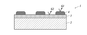
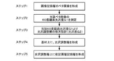
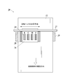
- Schematic sectional view showing an example of the configuration of an image recording material in which an image recording layer is formed on a substrate having a gloss adjustment layer Flow chart showing an example of an image forming process by the image recording method of the present invention.
- the image recording method of the present invention is an image recording method in which a gloss adjustment layer is provided on a base material and an image recording layer is formed on the gloss adjustment layer, and the 60-degree mirror gloss G1 of the image recording layer is previously determined.
- the 60-degree specular gloss G2 of the gloss adjusting layer is adjusted according to the information of the measured and obtained 60-degree specular gloss G1.
- the 60-degree specular gloss of the gloss adjustment layer is
- the gloss difference (G2-G1) between the degree G2 and the 60-degree specular gloss G1 of the image recording layer is in the range of ⁇ 20 to +20, and the gloss difference (G2-G1) is ⁇ 10 to +20.
- the range of +5 is preferable in that the difference in gloss between the image forming portion and the non-image forming portion can be further reduced and an image having no uncomfortable feeling can be formed.
- the gloss adjusting layer may be formed by a wet-type coating method using a coating liquid for forming a gloss adjusting layer containing 0.1 to 20% by mass of organic or inorganic fine particles having a specific particle size in the resin dispersion. It is preferable that the glossiness of the gloss adjustment layer can be adjusted to a desired 60-degree specular gloss G2 by applying an ink-jet printing method as a wet coating method, and further, by applying the ink-jet printing method.
- the image recording layer is formed using an actinic ray-curable inkjet ink
- the adhesiveness with the gloss adjusting layer is excellent, and the spread of wet dots is suppressed, and high scratch resistance with high quality is obtained. This is preferable in that an image can be obtained.
- the image recording layer with an actinic ray-curable inkjet ink containing a gelling agent prevents oxygen inhibition on the surface of the formed recorded image, and furthermore, as the gelling agent, the general formula (G1) or (G1).
- the general formula (G1) or (G1) any one of the compounds having the structure represented by G2) in a range of 0.1 to 5.0% by mass based on the total mass of the actinic ray-curable inkjet ink, and as a photopolymerizable compound; Containing an acrylate compound having a molecular weight in the range of 280 to 1500 and a ClogP value in the range of 4.0 to 7.0 in the range of 10 to 40% by mass, the effect of the present invention can be improved. It is preferable in that it can be expressed more.
- the average particle diameter r of the organic or inorganic fine particles contained in the gloss adjusting layer is in the range of 1.5 to 7.0 ⁇ m, and the film thickness hd after drying is in the range of 1.0 to 3.0 ⁇ m, Further, by designing the average particle diameter r of the organic or inorganic fine particles to be larger than the dried film thickness hd of the gloss adjusting layer, the 60-degree specular gloss G2 of the gloss adjusting layer can be adjusted to a desired condition. This is a more preferable aspect in that it can be set to.
- the resin dispersion contained in the gloss adjusting layer is a resin containing an acrylic component, or the organic fine particles contained in the gloss adjusting layer are acrylic fine particles, the object effect of the present invention, It is preferable in that it can be expressed.
- the image recording method of the present invention is an image recording method in which a gloss adjusting layer is provided on a base material and an image recording layer is formed on the gloss adjusting layer, and the image recording layer has a 60-degree specular glossiness (hereinafter referred to as “gloss”).
- G1 is measured by the method described below, and the 60-degree specular gloss G2 of the gloss adjustment layer is adjusted according to the obtained information of the 60-degree specular gloss G1 to record an image. It is characterized by doing.
- FIG. 1 is a schematic sectional view showing an example of the configuration of an image recording material in which an image recording layer is formed on a substrate having a gloss adjusting layer.
- the image recording material (1) formed by the image recording method of the present invention is adjusted to a gloss G2 (G2) on the substrate (2) in accordance with the gloss G1 (G1) of the image forming layer (4).
- a gloss adjusting layer (3) is provided on the entire surface, and an image forming material, for example, an inkjet ink is ejected onto the entire surface of the gloss adjusting layer (3) or to a specific region in accordance with a pattern of a formed image to form an image. How to do.
- FIG. 2 shows a process flow of image formation by the image recording method of the present invention.
- Step 1 First, a solid image of the image recording layer is formed on a base material, and a sample of an image recording layer single layer for measuring the glossiness of the image recording layer is prepared.
- Step 2 A 60-degree surface gloss G1 is measured for the solid image of the image recording layer prepared above in accordance with the method defined in JIS Z 8741.
- Step 3 Set the 60-degree surface gloss G2 of the gloss adjustment layer according to the obtained information of the 60-degree surface gloss G1 of the image recording layer.
- the gloss difference ⁇ G (G2 ⁇ G1) between the 60 ° surface gloss G2 of the gloss adjusting layer and the 60 ° surface gloss G1 of the image recording layer is preferably in the range of ⁇ 20 to +20, more preferably.
- the composition of the gloss adjusting layer is appropriately adjusted so as to fall within the range of ⁇ 10 to +5.
- the most effective method of adjusting the glossiness of the gloss adjustment layer is to form the gloss adjustment layer at least by dispersing a resin dispersion containing an aqueous solvent as a component (1) and a component (2).
- a gloss adjusting layer composed of organic or inorganic fine particles having a particle size in the range of 1.0 to 20 ⁇ m and containing the following component (2) in the range of 0.1 to 20% by mass with respect to the component (1).
- the type, particle size, and amount of the organic or inorganic fine particles are appropriately adjusted, and the composition of the coating liquid for forming a gloss adjusting layer for adjusting the gloss to a desired level is determined. I do.
- the average particle diameter r of the organic or inorganic fine particles is set to be larger than the thickness hd of the gloss adjusting layer after drying, that is, a form in which the upper surface of the organic or inorganic fine particles is exposed on the surface of the gloss adjusting layer. It is preferable to form an uneven structure.
- Step 4 The coating liquid for forming a gloss adjusting layer, the composition of which has been determined in Step 3, is applied to the substrate by an inkjet printing method or a wet coating method to form a gloss adjusting layer.
- Step 5 Finally, an image recording layer having the same configuration as that described in Step 1 is formed.
- the 60-degree specular glossiness referred to in the present invention is a value measured in accordance with a measurement method defined in JIS Z8741.
- Examples of the measuring device that can be used for measuring the 60-degree specular glossiness according to the present invention include, for example, a precision glossmeter GM-26D, a True Gloss GM-26DPRO, and a variable-angle glossmeter GM-3D (Murakami Color Technology Research) Incorporated), a variable-angle gloss meter VGS-10001DP (manufactured by Nippon Denshoku Industries Co., Ltd.), a digital variable-angle gloss meter (Suga Test Instruments Co., Ltd.) and the like.
- values measured using a gonio-gloss meter PG-1M and VGS-10001DP are applied.
- the substrate applicable to the image recording method of the present invention is not particularly limited as long as it can stably hold a gloss adjustment layer or an image recording layer formed thereon. It is preferable that the substrate has a gloss that does not largely deviate from the surface gloss G2.
- Examples of the base material applicable to the present invention include, for example, plain paper used for copying and the like, paper base material such as art paper, ordinary uncoated paper, and a base paper coated on both sides with a resin or the like.
- various non-absorbable plastics and films thereof used in so-called flexible packaging can be used.
- plastic films include polyethylene terephthalate (PET) and stretched polystyrene. (OPS), stretched polypropylene (OPP), stretched nylon (ONy), polyvinyl chloride (PVC), polyethylene (PE), and triacetyl cellulose (TAC) film.
- PET polyethylene terephthalate
- OPS stretched polystyrene.
- OPS stretched polypropylene
- PVC stretched nylon
- PVC polyvinyl chloride
- PE polyethylene
- TAC triacetyl cellulose
- polycarbonate (PP) acrylic resin
- ABS resin polyacetal
- PVA polyacetal
- rubbers and the like can be used.
- Examples of the plain paper applicable to the present invention include special printing paper such as high-grade printing paper, intermediate-grade printing paper, lower-grade printing paper, thin printing paper, finely-coated printing paper, color high-quality paper, foam paper, and PPC paper ( Copy paper) and other information papers.
- special printing paper such as high-grade printing paper, intermediate-grade printing paper, lower-grade printing paper, thin printing paper, finely-coated printing paper, color high-quality paper, foam paper, and PPC paper ( Copy paper) and other information papers.
- Examples of the art paper include OK Kinto N, Satin Kinto N, SA Kinto, Ultra Satin Kinto N, OK Ultra Aqua Satin, OK Kanto One Side, N Art Post, NK Special Double Side Art, Raitou Super Art N, Raito Super Art MN, Thunderbird Art N, Thunderbird Dall Art N, and the like.
- coated paper examples include POD gloss coat, OK top coat +, OK top coat S, aurora coat, mu coat, mu white, thunderbird coat N, utrilo coat, pearl coat, white pearl coat, POD mat coat, New Age, New Age W, OK Top Coat Mat N, OK Royal Court, OK Top Coat Dal, and the like.
- the gloss adjusting layer according to the present invention is obtained by coating a coating liquid for forming a gloss adjusting layer containing the following component (2) in the range of 0.1 to 20% by mass with respect to the following component (1) by inkjet printing or wet coating. It is preferably formed by a method.
- Component (1) a resin dispersion using an aqueous solvent as a dispersion medium
- Component (2) organic or inorganic fine particles having an average particle size in a range of 1.0 to 20 ⁇ m.
- the resin dispersion (hereinafter also referred to as resin emulsion or polymer latex) constituting the component (1) refers to a dispersion in which a water-insoluble hydrophobic polymer is dispersed as fine particles in water or a water-soluble dispersion medium.
- the polymer is emulsified in a dispersion medium, emulsion-polymerized, micelle-dispersed, or partially dispersed in polymer molecules and molecular chains themselves are molecularly dispersed. Any of them may be used.
- Examples of the main skeleton of the polymer dispersible in an aqueous solvent include polyethylene, polyethylene-polyvinyl alcohol (PVA), polyethylene-polyvinyl acetate, polyethylene-polyurethane, polybutadiene, polybutadiene-polystyrene, polyolefin copolymer, and polyamide (nylon).
- PVA polyethylene-polyvinyl alcohol
- polyethylene-polyvinyl acetate polyethylene-polyurethane
- polybutadiene polybutadiene-polystyrene
- polyolefin copolymer polyamide
- nylon polyamide
- Polyvinylidene chloride polyester, polyacrylate, polyacrylate-polyester, polyacrylate-polystyrene, polyvinyl acetate, polyurethane-polycarbonate, polyurethane-polyether, polyurethane-polyester, polyurethane-polyacrylate, silicone, silicone-polyurethane, silicone- Polyacrylate, polyvinylidene fluoride-polyacrylate, polyfluoroolefin-polyvinyl acrylate Le, and the like. Further, based on these skeletons, copolymerization using other monomers may be the main skeleton.
- polyester resin emulsions having an ester skeleton acrylic resin emulsions, polyester-acrylic resin emulsions, vinyl chloride-acrylic resin copolymer emulsions, and polyethylene resin emulsions having an ethylene skeleton are preferable, and particularly include an acrylic component.
- a resin emulsion is preferred in that the desired effects of the present invention can be further exhibited.
- Polysol FP3000 polyethylene resin, anion, core: acrylic, shell: polyester, manufactured by Showa Denko KK
- Vylonal MD1480 polyyester resin, anion, manufactured by Toyobo Co., Ltd.
- Vironal MD1245 polyyester resin, anion, Toyobo Co., Ltd.
- Vironal MD1500 polyyester resin, anion, manufactured by Toyobo
- Vironal MD2000 polyyester resin, anion, manufactured by Toyobo
- Vironal MD1930 polyyester resin, anion, manufactured by Toyobo
- Pluscoat RZ105 polyyester resin, anion
- Plus coat RZ570 polyyester resin, anion, made by TOKYO CHEMICAL
- plus coat RZ571 polyyester resin, anion, made by TOKYO CHEMICAL
- Polyester resins such as Elitel (manufactured by Unitika) and Byron (manufactured
- Polyethylene resins such as high-tech S-9242 (polyethylene resin, anion, manufactured by Toho Chemical Co., Ltd.) Resin, Movinyl 7720 (acrylic resin, nonion, manufactured by Nippon Synthetic Chemical Company), Movinyl 7820 (acrylic resin, nonion, manufactured by Nippon Synthetic Chemical Company), John Krill (manufactured by Johnson Polymer), Eslek P (manufactured by Sekisui Chemical Co., Ltd.) ), MFR 1924 (made by Michelman), Polytron (made by Asahi Kasei), Nipol series (made by ZEON) and the like.
- the polymer dispersible in the aqueous solvent may be one containing one of the above-mentioned polymers or a plurality thereof.
- Aqueous solvents applicable to the resin dispersion include not only pure water (including distilled water and deionized water), but also aqueous solutions containing acids, alkalis, salts, etc., aqueous organic solvents, or hydrophilic organic solvents. Solvent. Examples of the aqueous solvent include pure water (including distilled water and deionized water), alcoholic solvents such as methanol and ethanol, and mixed solvents of water and alcohol.
- the average particle size of the dispersed particles of the resin dispersion according to the present invention is not particularly limited, but is preferably in the range of 5 to 200 nm.
- the average particle size is 5 nm or more, aggregation of the particles can be suppressed, the dispersion stability can be improved, and the smoothness of the coated surface can be improved.
- the average particle size is 200 nm or less, haze of the gloss adjusting layer can be suppressed, and suitable performance as an image forming unit (substrate / gloss adjusting layer / image forming layer) to be formed can be obtained.
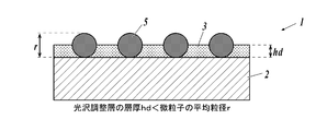
- the average particle diameter r of the organic or inorganic fine particles contained in the gloss adjusting layer is in the range of 1.5 to 7.0 ⁇ m, and the film thickness hd after drying is adjusted. Is in the range of 1.0 to 3.0 ⁇ m, and the thickness hd of the gloss adjusting layer after drying and the average particle diameter r of the organic or inorganic fine particles satisfy the condition defined by the following formula (1). Is a preferred embodiment.
- FIG. 3 is a schematic sectional view showing an example of the configuration of the gloss adjusting layer according to the present invention.
- the thickness of the gloss adjusting layer (3) mainly formed of a resin dispersion serving as a binder is defined as hd, and
- the average particle diameter of the organic or inorganic fine particles (5) contained in r is r
- the condition that each particle diameter satisfies r> hd is satisfied, and the organic or inorganic fine particles (5) are separated from the surface of the gloss adjusting layer (3).
- the upper portion of the fine particles (5) is exposed to form a convex structure, and by controlling the density of the convex structure or the height of the convex structure, the gloss G2 of the gloss adjusting layer is controlled to a desired characteristic. be able to.
- the value of the ratio of the average particle diameter r of the organic or inorganic fine particles / the thickness hd of the gloss adjusting layer is 1.01 or more, preferably 1.01 to 2.6, and more preferably 1.4. It is in the range of 2.12.1.
- organic or inorganic fine particles having an average particle size defined by component (2) in the range of 1.0 to 20 ⁇ m are mixed with the resin dispersion as component (1).
- the content is preferably in the range of 0.1 to 20% by mass.
- the average particle size in the present invention refers to a primary average particle size, which can be measured from an electron micrograph by a scanning electron microscope (SEM) or the like. It may be measured by a particle size distribution analyzer using a dynamic light scattering method, a static light scattering method, or the like.
- the average particle diameter of the primary particles, the particle itself or particles that appeared on the cross section or surface of the gloss adjustment layer is observed with an electron microscope, and the particle diameter of 1,000 arbitrary particles is measured. It is obtained as a simple average value (number average).
- the particle size of each particle is represented by a diameter assuming a circle equal to its projected area.
- inorganic fine particles As the inorganic fine particles applicable to the gloss adjusting layer according to the present invention, for example, SiO 2 , Al 2 O 3 , TiO 2 , SnO 2 , Sb 2 O 5 , Fe 2 O 3 , ZrO 2 , CeO 2 , Y 2 Examples include inorganic fine particles such as O 3 .
- Examples of commercially available inorganic fine particles include, for example, functional spherical silica HPS series (manufactured by Toagosei Co., Ltd.), “Sea Hostar” KE series (manufactured by Nippon Shokubai Co., Ltd.), and “particle size standard particles” 8000 series (manufactured by Nippon Shokubai Co., Ltd.).
- Allumina spherical fine particles such as Thermo @ Fisher @ Scientific
- Admatechs "Admafine” series (manufactured by Admatechs) and “High Pressica” series (Ube Nitto Kasei Co., Ltd.) Micron)
- Admatechs "Admafine” series (manufactured by Admatechs)
- Alumina manufactured by Nippon Light Metal Co., Ltd.
- Allumina Beads CB series (manufactured by Showa Denko KK), etc. Can be.
- silica particles are preferable, and examples thereof include Seahoster KE-P100 (average particle size: 1.0 ⁇ m) and KE-P150 (average particle size: 1.5 ⁇ m) manufactured by Nippon Shokubai Co., Ltd.
- organic fine particles examples include, for example, polyacrylate particles, acrylic resin particles such as polymethacrylate particles, polyamide resin particles such as nylon particles, polyethylene particles, and polyolefin particles such as polypropylene particles.
- Spherical resin particles made of generally known resins, such as resin particles, silicone resin particles, phenolic resin particles, polyurethane resin particles, styrene resin particles, and benzoguanamine resin particles.
- acrylic resin fine particles examples include acrylic resin fine particles manufactured by Soken Chemical Co., Ltd., such as Chemisnow MX-300 (average particle size: 3 ⁇ m) and MX-500. (Average particle size: 5 ⁇ m), MX-1000, MX-1500H, MR-2HG, MR-7HG, MR-10HG, MR-3GSN, MR-5GSN, MR-7G, MR-10G, MR-5C, MR- 7GC (average particle size: 6 ⁇ m), as acrylic resin fine particles manufactured by Sekisui Chemical Co., Ltd., MBX-5, MBX-8, MBX-12 MBX-15, MBX-20, MB20X-5, MB30X-5, MB30X-8, MB30X SBX-6, SBX-8, SBX-12, SBX-17, etc.
- acrylic resin fine particles manufactured by Soken Chemical Co., Ltd. such as Chemisnow MX-300 (average particle size: 3 ⁇ m) and MX-500. (Average
- Well is a chemical made of polyolefin resin fine particles Chemipearl W100, W200, W300, W308, W310, W400, W401, W405, W410, W500, WF640, W700, W800, W900, W950, WP100, and the like.
- the nylon particles include SP-500 (average particle size: 5 ⁇ m), SP-10 (average particle size: 10 ⁇ m), TR-1 (average particle size: 13 ⁇ m), and TR-2 (average particle size) manufactured by Toray Industries, Inc. (Diameter: 20 ⁇ m).
- the coating liquid for forming a gloss-adjusting layer used for forming the gloss-adjusting layer according to the present invention comprises, as a component (1), a resin dispersion containing an aqueous solvent as a dispersion medium, and as a component (2), an average particle diameter of 1.0 to It is a preferred embodiment to include organic or inorganic fine particles in the range of 20 ⁇ m, but there is no particular limitation on the preparation method, but there is no aggregation of the organic or inorganic fine particles, and a coating for forming a gloss adjusting layer having a uniform composition.
- organic or inorganic fine particles are added little by little to a dispersing solvent, for example, isopropanol (abbreviation: IPA) with stirring, predispersed, and the fine particles are aggregated.
- IPA isopropanol
- the gloss adjusting layer is preferably formed by a wet coating method using a coating liquid for forming a gloss adjusting layer containing the above-described components, and more preferably, inkjet printing is performed as the wet coating method. It is preferred to apply the method.
- An antioxidant an ultraviolet absorber, a plasticizer, a surfactant, and the like can be added to the coating liquid for forming a gloss adjusting layer, if necessary.
- wet coating method applicable to the present invention examples include spin coating, casting, screen printing, die coating, blade coating, roll coating, spray coating, curtain coating, and LB (Langmuir-blowing). Jet method), an ink jet printing method, etc., and it is particularly preferable to apply the ink jet printing method from the viewpoint of easily obtaining a uniform thin film and high productivity.
- an ink jet recording method using an ink jet ink as an image forming material a color toner containing a coloring material is electrophotographically processed on paper or a thin film film.
- the method can be applied to an electrophotographic method in which an image is formed by applying and fixing, a screen printing method or an offset printing method in which a pattern or the like is formed on a variety of substrates using a printing ink. It is preferable to apply the present invention to an ink jet recording system using an ink jet ink.
- aqueous inkjet inks die type, pigment type
- solvent inks actinic ray curable inkjet inks
- solid inkjet inks hot melt inks
- the image recording layer according to the present invention is preferably formed using an actinic ray-curable inkjet ink containing a photopolymerizable compound.
- an actinic ray-curable inkjet ink (hereinafter also referred to as an actinic ray-curable ink, a UV-curable ink, or simply an ink) suitable as a method for forming an image recording layer using a representative inkjet ink was applied. The method will be described in detail.
- the actinic ray-curable ink according to the present invention is mainly composed of a coloring material (eg, a pigment or a dye), a photopolymerizable compound, a photopolymerization initiator, a polymerization inhibitor, and the like.
- the actinic ray-curable ink according to the present invention contains a gelling agent.
- the actinic ray curable ink suitable for the present invention preferably contains at least a photopolymerizable compound having a function of curing with actinic light.
- the photopolymerizable compound may be any of a monomer, a polymerizable oligomer, a prepolymer, and a mixture thereof.
- the ink according to the present invention may contain only one kind of the photopolymerizable compound, or may contain two or more kinds thereof.
- the actinic rays referred to here are, for example, energy rays such as electron rays, ultraviolet rays, ⁇ rays, ⁇ rays, and X rays, preferably ultraviolet rays or electron rays.
- energy rays such as electron rays, ultraviolet rays, ⁇ rays, ⁇ rays, and X rays, preferably ultraviolet rays or electron rays.
- the photopolymerizable compound include a radical polymerizable compound and a cationic polymerizable compound, and are preferably a radical polymerizable compound.
- the content of the photopolymerizable compound is, for example, preferably in the range of 1 to 97% by mass based on the total mass of the ink according to the present invention, from the viewpoint of film properties such as curability and flexibility, and 30 to 70% by mass. More preferably, it is in the range of 95% by mass.
- the radical polymerizable compound applicable to the present invention is preferably an unsaturated carboxylate, and more preferably (meth) acrylate.
- (meth) acrylate means acrylate or methacrylate
- (meth) acryloyl group means acryloyl group or methacryloyl group
- (meth) acryl means acrylic Or methacrylic.
- Examples of the (meth) acrylate include isoamyl (meth) acrylate, stearyl (meth) acrylate, lauryl (meth) acrylate, octyl (meth) acrylate, decyl (meth) acrylate, isomyristyl (meth) acrylate, and isostearyl (meth).
- Examples of the above-mentioned modified products include ethylene oxide-modified (EO-modified) acrylate having an ethylene oxide group inserted therein and propylene oxide-modified (PO-modified) acrylate having propylene oxide inserted therein.
- EO-modified ethylene oxide-modified
- PO-modified propylene oxide-modified
- ⁇ Acrylate compound A with defined molecular weight and ClogP value> In the actinic ray-curable ink according to the present invention, as the radical polymerizable compound, a (meth) acrylate compound having a molecular weight in the range of 280 to 1500 and a ClogP value in the range of 4.0 to 7.0. (Hereinafter, also simply referred to as “(meth) acrylate compound A”).
- (Meth) acrylate compound A more preferably has two or more (meth) acrylate groups.
- the molecular weight of the (meth) acrylate compound A is in the range of 280 to 1500 as described above, and more preferably in the range of 300 to 800.
- the ink viscosity at 80 ° C. can be set to 3 to 20, preferably 7 to 14 mPa ⁇ s.
- the viscosity of the ink after landing is increased, and the penetration of the ink into the recording medium can be suppressed.
- the effect of suppressing a decrease in curability can be expected.
- a (meth) acrylate compound having a molecular weight of 1500 or less an excessive increase in the sol viscosity of the ink can be suppressed, and an improvement in the gloss uniformity of the coating film can be expected.
- the molecular weight of the (meth) acrylate compound A can be measured using the following commercially available software package 1 or 2.
- the actinic light type ink contains the (meth) acrylate compound A as at least a part of the photopolymerizable compound
- the (meth) acrylate compound having a ClogP value of less than 4.0 is converted to the photopolymerizable compound.
- the gloss value tends to be lower than that of the actinic ray curable ink used as the ink. Therefore, the use of the ink for forming an image on a recording medium having a relatively low 60 ° gloss value before the corona discharge treatment is preferable because the gloss difference between the printed portion and the non-printed portion can be reduced.
- the (meth) acrylate compound A has a higher hydrophobicity than the (meth) acrylate compound having a ClogP value of less than 4.0, a larger amount of the gelling agent repels and moves to the surface of the cured film of the ink to increase unevenness. As a result, it is considered that the gloss value of the printing portion decreases. Further, the ClogP value of the (meth) acrylate compound A is more preferably in the range of 4.5 to 6.0.
- log P value is a coefficient indicating the affinity of an organic compound for water and 1-octanol.
- the 1-octanol / water partition coefficient P is a distribution equilibrium when a trace amount of a compound is dissolved as a solute in a solvent of a two-liquid phase of 1-octanol and water, and is a ratio of equilibrium concentrations of the compounds in the respective solvents. Indicated by their log logP relative to the base 10. That is, the “log P value” is a logarithmic value of the partition coefficient of 1-octanol / water, and is known as an important parameter representing the hydrophilic / hydrophobic property of the molecule.
- ClogP value is a logP value calculated by calculation.
- the ClogP value can be calculated by a fragment method, an atom approach method, or the like. More specifically, to calculate the ClogP value, reference can be made to the literature (C. Hansch and A. Leo, "Substitute ⁇ Constants ⁇ For ⁇ Correlation ⁇ Analysis ⁇ in ⁇ Chemistry ⁇ and ⁇ Biology” (John, Wiley, N.Way, & Fragment). Or the following commercially available software package 1 or 2.
- the amount of the (meth) acrylate compound A contained in the ink is not particularly limited, but is preferably in the range of 1 to 40% by mass, and more preferably in the range of 5 to 30% by mass based on the total mass of the ink. More preferred.
- the amount of the (meth) acrylate compound A is 1% by mass or more, the ink does not become too hydrophilic, and the gelling agent is sufficiently dissolved in the ink, so that the ink easily undergoes a sol-gel phase transition.
- the photopolymerization initiator can be sufficiently dissolved in the ink.
- More preferred examples of the (meth) acrylate compound A include (1) a trifunctional or higher functional compound having 3 to 14 structures represented by (—C (CH 3 ) H—CH 2 —O—) in the molecule. Methacrylate or acrylate compounds and (2) bifunctional or higher methacrylate or acrylate compounds having a cyclic structure in the molecule are included. These (meth) acrylate compounds have high photocurability and little shrinkage when cured. Furthermore, the reproducibility of the sol-gel phase transition is high.
- a trifunctional or higher methacrylate or acrylate compound having 3 to 14 structures represented by (—C (CH 3 ) H—CH 2 —O—) in a molecule is, for example, a compound having three or more hydroxy groups.
- the compound has a hydroxy group modified with propylene oxide, and the resulting modified product is esterified with (meth) acrylic acid.
- this compound examples include: 3PO-modified trimethylolpropane triacrylate Photomer 4072 (molecular weight: 471, ClogP: 4.90, manufactured by Cognis), 3PO-modified trimethylolpropane triacrylate Miramer M360 (molecular weight: 471, ClogP: 4.90, manufactured by Miwon) Etc. are included.
- the bifunctional or higher methacrylate or acrylate compound having a cyclic structure in the molecule is, for example, a compound obtained by esterifying a hydroxy group of a compound having two or more hydroxy groups and tricycloalkane with (meth) acrylic acid. .
- Tricyclodecane dimethanol diacrylate NK ester A-DCP (molecular weight: 304, ClogP: 4.69)
- Tricyclodecane dimethanol dimethacrylate NK ester DCP (molecular weight: 332, ClogP: 5.12) Etc.
- (meth) acrylate compound A examples include 1,10-decanediol dimethacrylate ⁇ NK ester DOD-N (molecular weight: 310, ClogP: 5.75, manufactured by Shin-Nakamura Chemical Co., Ltd.).
- the photopolymerizable compound may further contain a photopolymerizable compound other than the (meth) acrylate compound A.
- photopolymerizable compounds include, for example, (meth) acrylate monomers or oligomers having a ClogP value of less than 4.0, (meth) acrylate monomers or oligomers having a ClogP value of more than 7.0, and other polymerizable compounds. Oligomers and the like.
- Examples of these (meth) acrylate monomers or oligomers include 4EO-modified hexanediol diacrylate (CD561, manufactured by Sartomer, molecular weight 358); 3EO-modified trimethylolpropane triacrylate (SR454, manufactured by Sartomer, molecular weight 429); 4EO-modified pentaerythritol tetraacrylate (SR494, manufactured by Sartomer, molecular weight 528); 6EO-modified trimethylolpropane triacrylate (SR499, manufactured by Sartomer, molecular weight 560); caprolactone acrylate (SR495B, manufactured by Sartomer, molecular weight 344); polyethylene glycol Diacrylate (NK ester A-400, manufactured by Shin-Nakamura Chemical Co., molecular weight 508), (NK ester A-600, Shin-Nakamura Chemical Polyethylene glycol dimethacrylate (NK ester 9G, manufactured by Shin-Nakamura Chemical
- Examples of other polymerizable oligomers include epoxy acrylate, aliphatic urethane acrylate, aromatic urethane acrylate, polyester acrylate, linear acrylic oligomer and the like.
- Examples of the cationically polymerizable compound applicable to the present invention include an epoxy compound, a vinyl ether compound, and an oxetane compound.
- the ink may contain only one kind of the cationic polymerizable compound or two or more kinds thereof.
- the epoxy compound is an aromatic epoxide, an alicyclic epoxide, an aliphatic epoxide, or the like, and is preferably an aromatic epoxide or an alicyclic epoxide in order to enhance curability.
- the aromatic epoxide can be a di- or polyglycidyl ether obtained by reacting a polyhydric phenol or an alkylene oxide adduct thereof with epichlorohydrin.
- polyhydric phenol or its alkylene oxide adduct to be reacted examples include bisphenol A or its alkylene oxide adduct.
- the alkylene oxide in the alkylene oxide adduct may be ethylene oxide, propylene oxide, or the like.
- the alicyclic epoxide may be a cycloalkane oxide-containing compound obtained by epoxidizing a cycloalkane-containing compound with an oxidizing agent such as hydrogen peroxide or peracid.
- the cycloalkane in the cycloalkane oxide-containing compound can be cyclohexene or cyclopentene.
- the aliphatic epoxide can be a di- or polyglycidyl ether obtained by reacting an aliphatic polyhydric alcohol or an alkylene oxide adduct thereof with epichlorohydrin.
- Examples of aliphatic polyhydric alcohols include alkylene glycols such as ethylene glycol, propylene glycol, and 1,6-hexanediol.
- the alkylene oxide in the alkylene oxide adduct may be ethylene oxide, propylene oxide, or the like.
- vinyl ether compounds include ethyl vinyl ether, n-butyl vinyl ether, isobutyl vinyl ether, octadecyl vinyl ether, cyclohexyl vinyl ether, hydroxybutyl vinyl ether, 2-ethylhexyl vinyl ether, cyclohexane dimethanol monovinyl ether, n-propyl vinyl ether, isopropyl vinyl ether, and isopropenyl ether.
- Monovinyl ether compounds such as -o-propylene carbonate, dodecyl vinyl ether, diethylene glycol monovinyl ether, octadecyl vinyl ether; Diethylene glycol divinyl ether, diethylene glycol divinyl ether, triethylene glycol divinyl ether, propylene glycol divinyl ether, dipropylene glycol divinyl ether, butanediol divinyl ether, hexanediol divinyl ether, cyclohexane dimethanol divinyl ether, trimethylolpropane trivinyl ether, etc. Or a trivinyl ether compound.
- a di- or trivinyl ether compound is preferable in consideration of curability and adhesion.
- the oxetane compound is a compound having an oxetane ring, and examples thereof include oxetane compounds described in JP-A-2001-220526, JP-A-2001-310937, JP-A-2005-255821, and the like. .
- the compound represented by the general formula (1) described in paragraph (0089) of JP-A-2005-255821 and the compound represented by the general formula (2) described in paragraph (0092) of the same publication Compound, compound represented by general formula (7) described in paragraph number (0107) of the same publication, compound represented by general formula (8) described in paragraph number (0109) of the same publication, Examples include the compound represented by the general formula (9) described in paragraph (0116) of the gazette.
- the actinic ray-curable ink applied to the image recording method of the present invention preferably contains a gelling agent, and further, the gelling agent is represented by the following general formula (G1) or general formula (G2). It is preferable that the compound has the structure represented.
- the gelling agent has a function of temporarily fixing (pinning) the ink droplets that have landed on the base material or the gloss adjusting layer in a gel state.
- the ink containing the gelling agent is pinned in a gel state, the spread of the ink is suppressed and the adjacent dots are hardly united, so that a higher definition image can be formed.
- the gelling agent preferably crystallizes at a temperature equal to or lower than the gelling temperature of the ink.
- the gelling temperature refers to a temperature at which the gelling agent undergoes a phase transition from a sol to a gel when the sol or liquid ink is cooled by heating, and the viscosity of the ink rapidly changes. Specifically, the sol or liquid ink is cooled while measuring the viscosity with a viscoelasticity measuring device (for example, MCR300, manufactured by Anton Paar), and the temperature at which the viscosity sharply rises is measured. Gelation temperature.
- a so-called card house structure When the gelling agent crystallizes in the ink, a structure in which the photopolymerizable compound is included in the three-dimensional space formed by the gelling agent crystallized in a plate shape, a so-called card house structure is formed.
- the card house structure When the card house structure is formed, the liquid photopolymerizable compound is held in the space, so that the ink droplets are less likely to wet and spread, and the pinning property of the ink is further improved.
- the ink pinning property increases, ink droplets that have landed on the recording medium are less likely to coalesce, and a higher definition image can be formed.
- the photopolymerizable compound dissolved in the ink and the gelling agent are compatible.
- gelling agents suitable for forming a card house structure include aliphatic ketones, aliphatic esters, petroleum waxes, vegetable waxes, animal waxes, mineral waxes, hydrogenated castor oil, modified waxes, higher fatty acids, Includes higher alcohols, hydroxystearic acid, fatty acid amides including N-substituted fatty acid amides and special fatty acid amides, higher amines, esters of sucrose fatty acids, synthetic waxes, dibenzylidene sorbitol, dimer acid and dimer diol.
- aliphatic ketones, aliphatic esters, higher fatty acids, and higher alcohols having a hydrocarbon group having 9 to 25 carbon atoms are preferable from the viewpoint of further improving pinning properties.
- the gelling agent only one kind may be contained in the ink, or two or more kinds may be contained in the ink.
- aliphatic ketones examples include dilignoseryl ketone, dibehenyl ketone, distearyl ketone, dieicosyl ketone, dipalmityl ketone, dilauryl ketone, dimyristyl ketone, myristyl palmityl ketone and palmityl stearyl ketone. It is.
- aliphatic ester examples include fatty acid esters of monoalcohols such as behenyl behenate, icosyl icosanoate, oleyl palmitate; glycerin fatty acid ester, sorbitan fatty acid ester, propylene glycol fatty acid ester, ethylene glycol fatty acid ester and polyoxyethylene fatty acid ester. And fatty acid esters of polyhydric alcohols.
- Examples of commercially available products of the above-mentioned aliphatic esters include the EMALEX series, manufactured by Nippon Emulsion Co., Ltd. (“EMALEX” is a registered trademark of the company), the Riquemar series and Poem series, manufactured by Riken Vitamin Co., Ltd. (“Riquemar” and “Poem” are Both are registered trademarks of the company).
- higher fatty acids examples include behenic acid, arachidic acid, stearic acid, palmitic acid, myristic acid, lauric acid, oleic acid, and erucic acid.
- Examples of higher alcohols include stearyl alcohol and behenyl alcohol.
- an aliphatic ketone represented by the following general formula (G1) or an aliphatic ester represented by the following general formula (G2) is particularly preferable.
- R 1 —CO—R 2 R 1 —CO—R 2
- R 1 and R 2 each independently represent an alkyl group containing a straight-chain portion having 12 to 26 carbon atoms and optionally containing a branch.
- R 3 —COO—R 4 each independently represent an alkyl group containing a straight-chain portion having 12 to 26 carbon atoms and optionally containing a branch.
- the linear or branched hydrocarbon group has 12 or more carbon atoms, and therefore, the aliphatic ketone represented by the general formula (G1) or the general formula (G2)
- the crystallinity of the aliphatic ester represented by the formula (1) is higher, and more sufficient space is generated in the card house structure. Therefore, the photopolymerizable compound is easily included in the space sufficiently, and the pinning property of the ink is further improved.
- the aliphatic ketone represented by the general formula (G1) or the aliphatic ester represented by the general formula (G2) has a melting point of There is no need to overheat the ink when ejecting it without rising too much.
- Examples of the aliphatic ketone represented by the general formula (G1) include dilignoseryl ketone (carbon number: 23 to 24), dibehenyl ketone (carbon number: 21 to 22), and distearyl ketone (carbon number: 17 to 17).
- dieicosyl ketone (carbon number: 19 to 20), dipalmityl ketone (carbon number: 15 to 16), dimyristyl ketone (carbon number: 13 to 14), dilauryl ketone (carbon number: 11) To 12), lauryl myristyl ketone (carbon number: 11 to 14), lauryl palmityl ketone (carbon number: 11 to 16), myristyl palmityl ketone (carbon number: 13 to 16), myristyl stearyl ketone (carbon number: 13) To 18), myristyl behenyl ketone (C: 13 to 22), palmityl stearyl ketone (C: 15 to 18), and valmicil behenyl ketone (C: 15-22) and stearyl behenyl ketone (carbon number: 17-22) are included.
- the carbon number in parentheses indicates the carbon number of each of the two hydrocarbon groups separated by the carbonyl group.
- Examples of commercial products of the aliphatic ketone represented by the general formula (G1) include 18-Pentriacontanon, manufactured by Alfa Aeser, Hentriacontan-16-on, manufactured by Alfa Aeser, Kaowax T-1, and Kao. included.
- Examples of the aliphatic ester represented by the general formula (G2) include behenyl behenate (carbon number: 21 to 22), icosyl icosanoate (carbon number: 19 to 20), stearyl stearate (carbon number: 17 to 20).
- Examples of commercially available products of the aliphatic ester represented by the general formula (G2) include Unistar M-2222SL andsperm Acet, manufactured by NOF Corporation (“UNISTAR” is a registered trademark of the company), Exepar SS and Exepal MY-M, Manufactured by Kao Corporation (“Exepearl” is a registered trademark of the company), EMALEX @ CC-18 and EMALEX @ CC-10, manufactured by Nippon Emulsion Co., Ltd. (“EMALEX” is a registered trademark of the company) Includes the company's registered trademark).
- the content of the gelling agent is preferably in the range of 1.0 to 10.0% by mass based on the total mass of the ink.
- the content of the gelling agent is preferably in the range of 1.0 to 10.0% by mass based on the total mass of the ink.
- the content of the gelling agent is more preferably in the range of 1.0 to 7.0% by mass, and more preferably in the range of 2.0 to 5.0% by mass, based on the total mass of the ink. More preferably, it is most preferably in the range of 2.5 to 4.0% by mass.
- the photopolymerization initiator is a photoradical initiator when the photopolymerizable compound is a radical polymerizable compound, and is a photoacid generator when the photopolymerizable compound is a cationic polymerizable compound.
- the photopolymerization initiator may contain only one type or two or more types in the ink.
- the photopolymerization initiator may be a combination of both a photoradical initiator and a photoacid generator.
- the photo radical initiator may be a cleavage type radical initiator or a hydrogen abstraction type radical initiator.
- cleavage radical initiators include diethoxyacetophenone, 2-hydroxy-2-methyl-1-phenylpropan-1-one, benzyldimethylketal, 1- (4-isopropylphenyl) -2-hydroxy-2- Methylpropan-1-one, 4- (2-hydroxyethoxy) phenyl- (2-hydroxy-2-propyl) ketone, 1-hydroxycyclohexyl-phenylketone, 2-methyl-2-morpholino (4-thiomethylphenyl) Acetophenone-based initiators including propan-1-one and 2-benzyl-2-dimethylamino-1- (4-morpholinophenyl) -butanone; benzoin-based initiators including benzoin, benzoin methyl ether and benzoin isopropyl ether; 2,4,6-trimethylbenzoin dife Acylphosphine oxide initiators including Le phosphine oxide, benzyl and methyl phenylglyoxylate ester.
- hydrogen abstracting radical initiators include benzophenone, methyl-4-phenylbenzophenone o-benzoylbenzoate, 4,4'-dichlorobenzophenone, hydroxybenzophenone, 4-benzoyl-4'-methyl-diphenyl sulfide, acrylated Benzophenone-based initiators including benzophenone, 3,3 ', 4,4'-tetra (t-butylperoxycarbonyl) benzophenone and 3,3'-dimethyl-4-methoxybenzophenone, 2-isopropylthioxanthone, 2,4- Thioxanthone-based initiators including dimethylthioxanthone, 2,4-diethylthioxanthone and 2,4-dichlorothioxanthone, aminobenzophenone-based initiators including Michler's ketone and 4,4'-diethylaminobenzophenone, 1 - butyl-2-chloro acridone, 2-
- photoacid generators examples include compounds described in “Organic Materials for Imaging”, edited by Society for Research on Organic Electronics Materials, Bunshin Publishing (1993), pp. 187-192.
- the content of the photopolymerization initiator may be within a range that can sufficiently cure the photopolymerizable compound, and may be, for example, within a range of 0.01 to 10% by mass based on the total mass of the ink.
- the actinic ray-curable ink applied to the present invention further includes other components such as a photopolymerization initiator auxiliary, a polymerization inhibitor, a polymer dispersant, and a surfactant within a range where the effects of the present invention can be obtained. It may be.
- the actinic ray-curable ink applied to the present invention may further contain a photopolymerization initiator auxiliary agent, a polymerization inhibitor, and the like, if necessary.
- the photopolymerization initiator assistant may be a tertiary amine compound, and is preferably an aromatic tertiary amine compound.
- aromatic tertiary amine compounds include N, N-dimethylaniline, N, N-diethylaniline, N, N-dimethyl-p-toluidine, N, N-dimethylamino-p-benzoic acid ethyl ester, N, N-dimethylamino-p-benzoic acid isoamylethyl ester, N, N-dihydroxyethylaniline, triethylamine, N, N-dimethylhexylamine and the like are included.
- N, N-dimethylamino-p-benzoic acid ethyl ester and N, N-dimethylamino-p-benzoic acid isoamylethyl ester are preferred. These compounds may be used alone or in combination of two or more.
- polymerization inhibitors include (alkyl) phenol, hydroquinone, catechol, resorcinol, p-methoxyphenol, t-butylcatechol, t-butylhydroquinone, pyrogallol, 1,1-picrylhydrazyl, phenothiazine, p-benzoquinone , Nitrosobenzene, 2,5-di-t-butyl-p-benzoquinone, dithiobenzoyl disulfide, picric acid, cuperon, aluminum N-nitrosophenylhydroxylamine, tri-p-nitrophenylmethyl, N- (3-oxyanilino- 1,3-dimethylbutylidene) aniline oxide, dibutyl cresol, cyclohexanone oxime cresol, guaiacol, o-isopropylphenol, butyraldoxime, methyl ethyl ketoxime, cyclohexanone oxime
- polymer dispersant for example, a hydroxy group-containing carboxylic acid ester, a salt of a long-chain polyaminoamide and a high-molecular-weight acid ester, a salt of a high-molecular-weight polycarboxylic acid, a salt of a long-chain polyaminoamide and a polar acid ester, and a high-molecular-weight unsaturated ester Acid esters, polymer copolymers, modified polyurethanes, modified polyacrylates, polyetherester-type anionic activators, naphthalenesulfonic acid formalin condensate salts, aromatic sulfonic acid formalin condensate salts, polyoxyethylene alkyl phosphate, Polyoxyethylene nonylphenyl ether, stearylamine acetate and the like can be mentioned.
- polymer dispersant for example, a comb-type block copolymer having a basic group may be used.
- the comb-type block copolymer in the comb-type block copolymer having a basic group refers to a graft polymer formed on a linear polymer forming a main chain and each structural unit derived from a monomer forming the linear main chain. And another type of polymer.
- a long-chain polyoxyalkyl group (EO-PO copolymer group) is preferable.
- the comb-type block copolymer include those in which the main chain is a polymer of an acrylate ester and the side chain is a long-chain polyoxyalkyl group (EO-PO copolymer group).
- the basic group in the comb-type block copolymer having a basic group is preferably a quaternary, tertiary, secondary or primary amine group.
- the weight average molecular weight of the polymer dispersant is preferably in the range of 1,000 to 50,000, more preferably in the range of 5,000 to 30,000.
- the weight average molecular weight of the polymer dispersant can be determined by gel permeation chromatography (GPC method) in terms of polystyrene.
- Examples of commercially available polymer dispersants containing a basic group include DISPERBYK-109, 161, 168, 180, 2013, 2155, BYKJET-9150 and BYKJET-9151 manufactured by BYK; Efka-4431 manufactured by BASF. PX4701; PB-821, 822, 824 manufactured by Ajinomoto Fine-Techno; Solsperse 24000GR, 32000, 39000, 71000, and J-200 manufactured by Lubrizol.
- DISPERBYK” and “BYKJET” are registered trademarks of BYK
- "Efka” is a registered trademark of BASF
- Solsperse” is a registered trademark of Lubrizol.
- the content of the polymer dispersant is preferably in the range of 30 to 70% by mass based on the total mass of the pigment.
- the content of the polymer dispersant is 30% by mass or more with respect to the pigment, not only can the aggregation of the pigment be less likely to occur, but also the interaction between the pigment and the gelling agent can be effectively suppressed, Gloss variation and dot diameter variation under high-temperature storage can be further suppressed.
- the content of the polymer dispersant is more than 70% by mass with respect to the pigment, the extra polymer dispersant that does not contribute to the pigment dispersion causes gelation inhibition, resulting in an increase in the initial gloss value and the initial dot diameter. I will.
- the content of the polymer dispersant is more preferably in the range of 35 to 65% by mass based on the total mass of the pigment.
- the inkjet dispersant of the present invention may contain only one kind of polymer dispersant or two or more kinds thereof.
- the pigment and the polymer dispersant can be dispersed by, for example, a ball mill, sand mill, attritor, roll mill, agitator, Henschel mixer, colloid mill, ultrasonic homogenizer, pearl mill, wet jet mill, or paint shaker.
- surfactants examples include anionic surfactants such as dialkyl sulfosuccinates, alkyl naphthalene sulfonates and fatty acid salts, polyoxyethylene alkyl ethers, polyoxyethylene alkyl allyl ethers, acetylene glycols and polyoxy Nonionic surfactants such as ethylene-polyoxypropylene block copolymers, cationic surfactants such as alkylamine salts and quaternary ammonium salts, and silicone-based and fluorine-based surfactants are included.
- anionic surfactants such as dialkyl sulfosuccinates, alkyl naphthalene sulfonates and fatty acid salts
- polyoxyethylene alkyl ethers polyoxyethylene alkyl allyl ethers
- acetylene glycols acetylene glycols
- Nonionic surfactants such as ethylene-polyoxypropylene block copolymers
- silicone-based surfactant examples include polyether-modified polysiloxane compounds, specifically, KF-351A, KF-352A, KF-642 and X-22-4272, BYK307, BYK345, manufactured by Shin-Etsu Chemical Co., Ltd. BYK347 and BYK348, manufactured by Big Chemie (“BYK” is a registered trademark of the company), and TSF4452, manufactured by Momentive Performance Materials.
- fluorinated surfactant means a substance in which part or all of a normal surfactant is replaced with fluorine instead of hydrogen bonded to carbon of a hydrophobic group.
- fluorine-based surfactants include Megafac @ F, manufactured by DIC ("Megafac” is a registered trademark of the company), Surflon, AGC Seika Chemical Co., Ltd. (“Sulflon” is a registered trademark of the company), Fluorad @ FC, 3M (“Fluorad” is a registered trademark of the company), Monflor, manufactured by Imperial Chemical Industry Co., Ltd., Zonyls, manufactured by E. I. Dupont de Nemours & Company, Licowet® VPF, manufactured by Rubeberke Hoechst, And FTERGENT, manufactured by Neos (“FTERGENT” is a registered trademark of the company).
- the amount of the surfactant can be arbitrarily set as long as the effects of the present invention can be obtained.
- the amount of the surfactant can be, for example, 0.001% by mass or more and less than 1.0% by mass based on the total mass of the ink.
- Color material As the coloring material applicable to the actinic ray-curable ink according to the present invention, a dye or a pigment can be applied, and the ink has good dispersibility with respect to the components of the ink, and has excellent weather resistance. And pigments are more preferred.
- an oil-soluble dye or the like can be used as the dye.
- the oil-soluble dye include the following various dyes.
- magenta dyes include MS Magenta VP, MS Magenta HM-1450, MS Magenta HSo-147 (all manufactured by Mitsui Toatsu), AIZENSOT Red-1, AIZEN SOT Red-2, AIZEN SOTRed-3, AIZEN SOT Pink-1, SPIRON Red GEH SPECIAL (all manufactured by Hodogaya Chemical Co., Ltd.), RESOLIN Red FB 200%, MACROLEX Red Violet R, MACROLEX ROT5B (all manufactured by Bayer Japan), KAYASET RedB, KAYASET REDA 802 (all manufactured by Nippon Kayaku Co., Ltd.), PHLOXIN, ROSE BENGAL, ACID Red (all manufactured by Daiwa Kasei), HSR-31, DIAR SIN Red K (manufactured by Mitsubishi Kasei Co.,
- cyan dyes examples include MS Cyan HM-1238, MS Cyan HSo-16, Cyan HSo-144, and MS Cyan VPG (all manufactured by Mitsui Toatsu), AIZEN SOT Blue-4 (manufactured by Hodogaya Chemical), RESOLIN @ BR. Blue BGLN 200%, MACROLEX Blue RR, CERES Blue GN, SIRIUS SUPRATURQ. Blue @ Z-BGL, SIRIUS @ SUPRA @ TURQ. Blue FB-LL 330% (all manufactured by Bayer Japan), KAYASET Blue FR, KAYASET Blue N, KAYASET Blue 814, Turq.
- Blue GL-5 200 Light Blue BGL-5 200 (manufactured by Nippon Kayaku), DAIWA Blue 7000, Oleosol Fast Blue GL (manufactured by Daiwa Kasei), DIAREIN Blue P (manufactured by Mitsubishi Chemical Corporation) Blue 670, NEOPEN Blue 808, and ZAPON Blue 806 (all manufactured by BASF Japan).
- yellow dyes examples include MS Yellow HSm-41, Yellow KX-7, Yellow EX-27 (Mitsui Toatsu), AIZEN SOT Yellow-1, AIZEN SOT YellowW-3, AIZEN SOT Yellow-6 (or more, Hodogaya) MACROLEX Yellow 6G, MACROLEX FLUOR.
- black dyes examples include MS Black VPC (manufactured by Mitsui Toatsu), AIZEN SOT Black-1, AIZEN SOT Black-5 (manufactured by Hodogaya Chemical Co., Ltd.), RESOLIN Black GSN 200%, RESOLIN Black BS (managed by KAYASET Black AN (manufactured by Nippon Kayaku), DAIWA Black MSC (manufactured by Daiwa Kasei), HSB-202 (manufactured by Mitsubishi Chemical), NEPTUNE Black X60, NEOPEN Black X58 (above, BASF) Japan Co., Ltd.).
- a pigment as a coloring material it is preferable to apply a pigment as a coloring material to the actinic ray-curable ink according to the present invention, and the pigment is not particularly limited.
- organic pigments having the following numbers described in the color index (CI) or Inorganic pigments can be mentioned.
- red or magenta pigments examples include Pigment Red 3, 5, 19, 22, 31, 38, 43, 48: 1, 48: 2, 48: 3, 48: 4, 48: 5, 49: 1, 53 : 1, 57: 1, 57: 2, 58: 4, 63: 1, 81, 81: 1, 81: 2, 81: 3, 81: 4, 88, 104, 108, 112, 122, 123, 144 , 146, 149, 166, 168, 169, 170, 177, 178, 179, 184, 185, 208, 216, 226, 257, Pigment Violet 3, 19, 23, 29, 30, 37, 50, 88, Pigment Orange # 13, 16, 20, 36, etc. are included.
- Examples of blue or cyan pigments include Pigment Blue 1, 15, 15: 1, 15: 2, 15: 3, 15: 4, 15: 6, 16, 17-1, 22, 27, 28, 29, 36. , 60 etc. are included.
- Examples of green pigments include Pigment Green 7, 26, 36, 50.
- Examples of yellow pigments include Pigment Yellow 1, 3, 12, 13, 14, 17, 34, 35, 37, 55, 74, 81, 83, 93, 94, 95, 97, 108, 109, 110, and 137. , 138, 139, 153, 154, 155, 157, 166, 167, 168, 180, 185, 193 and the like.
- Examples of black pigments include Pigment Black 7, 28, 26, and the like.
- Examples of commercially available pigments include Chromofine Yellow 2080, 5900, 5930, AF-1300, 2700L, Chromofine Orange 3700L, 6730, Chromofine Scarlet 6750, Chromofine Magenta 6880, 6886, 6891N, 6790, 6887, and Chromofine Yellow.
- Fine Violet RE Chromo Fine Red 6820, 6830, Chromo Fine Blue HS-3, 5187, 5108, 5197, 5085N, SR-5020, 5026, 5050, 4920, 4927, 4937, 4824, 4933GN-EP, 4940, 4973, 5205, 5208, 5214, 5221, 5000P, Chromofine Green 2GN, 2GO, 2G-550D, 5310, 5370, 6830, Chromofine Black A-1103, Seika Fast Yellow 10GH, A-3, 2035, 2054, 2200, 2270, 2300, 2400 (B), 2500, 2600, ZAY-260, 2700 (B), 2770, Seika Fast Red 8040, C405 (F), CA120, LR-116, 1531B, 8060R, 1547, ZAW-262, 1537B, GY, 4R-4016, 3820, 3891, ZA-215, Seika Fast Carmin 6B1476T-7, 1483LT, 3840, 3870
- titanium oxide particularly rutile type titanium dioxide
- white pigment can be used as the white pigment.
- the volume average particle diameter of the pigment is preferably 0.08 to 0.5 ⁇ m.
- the maximum particle size of the pigment is preferably 0.3 to 10 ⁇ m, more preferably 0.3 to 3 ⁇ m.
- the amount of the coloring material contained in the actinic ray-curable ink is preferably in the range of 0.1 to 20% by mass, and more preferably in the range of 0.4 to 10% by mass based on the total mass of the ink. Is more preferable. If the content of the pigment or the dye is too small, the color of the obtained image is not sufficient, and if the content is too large, the viscosity of the ink is increased, and the ejection property is reduced.
- Image recording method As a method that can suitably use the image recording method of the present invention, an ink jet recording method, an electrophotographic method, a printing method using ink, and the like can be applied. The method will be described.
- Ink jet recording apparatuses of the actinic ray curable ink jet type include a line recording method (also referred to as a single pass recording method) and a serial recording method (also referred to as a scanning method).
- the line recording method is preferable from the viewpoint of high-speed recording, though it may be selected according to the required image resolution and recording speed.
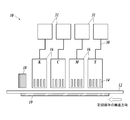
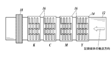
- the ink jet recording apparatus shown in FIGS. 4A and 4B is a recording apparatus for a line recording system.
- FIG. 4A is a side view of an example of a configuration of a main part of the ink jet recording apparatus
- FIG. 4B is a top view thereof.
- the ink jet recording apparatus (10) includes a head carriage (16) accommodating a plurality of ink discharge recording heads (14), and a base material (12) on which a gloss adjusting layer is formed. And an temperature control unit (18) disposed on the lower surface of the base material (12) and an actinic ray irradiation unit (18) disposed on the downstream side of the head carriage (16) in the conveyance direction of the base material. 19).
- a plurality of recording heads (14) for each color ink are fixedly arranged on the head carriage (16) so as to cover the entire width of the base material (12).
- Ink is supplied to the ink discharge recording head (14).
- ink is supplied to the recording head (14) for ink ejection directly from the ink cartridge (31) or the like, which is detachably mounted on the ink jet recording apparatus (10), or by the ink supply means (30). May be.
- An image recording layer is formed by transporting the base material (12) having a gloss adjustment layer with a controlled glossiness under the fixed head carriage (16).
- a plurality of ink discharge recording heads (14) are arranged in the transport direction of the base material (12) for each color.
- the number of ink discharge recording heads (14) arranged in the transport direction of the substrate (12) is set according to the nozzle density of the ink discharge recording head (14) and the resolution of a printed image. For example, when an image having a resolution of 1440 dpi is formed using a recording head (14) for ink ejection having a droplet amount of 2 pL and a nozzle density of 360 dpi, four ink ejection heads are arranged in the transport direction of the substrate (12). What is necessary is just to displace the recording head (14).
- dpi represents the number of ink droplets (dots) per inch. One inch is 2.54 cm.
- the actinic ray irradiator (18) covers the entire width of the substrate (12), and is disposed downstream of the head carriage (16) in the transport direction of the substrate (12).
- the actinic ray irradiating section (18) irradiates actinic rays to droplets ejected by the ink ejection recording head (14) and landed on the gloss adjustment layer of the base material (12), thereby curing the droplets.
- an actinic ray irradiation unit such as a metal halide lamp or an LED lamp is disposed so as to cover the entire width of the substrate (12), and after the ink lands on the substrate (12). Immediately, the metal is irradiated with ultraviolet rays by a ride lamp or the like, and the image is completely fixed.
- examples of the actinic ray irradiation section include a fluorescent tube (for example, a low-pressure mercury lamp, a germicidal lamp, etc.), a cold cathode tube, an ultraviolet laser, and several hundred Pa to 1 MPa.
- an ultraviolet irradiation unit that irradiates ultraviolet light having an illuminance of 100 mW / cm 2 or more, specifically, a high-pressure mercury lamp, a metal halide lamp, or an LED is preferable.
- a water-cooled LED manufactured by Phoseon Technology (wavelength: 395 nm) can be used.
- examples of the actinic ray irradiator include electron beam irradiating means such as a scanning method, a curtain beam method, and a broad beam method. From the viewpoint, curtain beam type electron beam irradiation means is preferable.
- Examples of the electron beam irradiation means include “Curetron EBC-200-20-30” manufactured by Nissin High Voltage Co., Ltd., “Min-EB” manufactured by AIT, and the like.
- the temperature control unit (19) is arranged on the lower surface of the substrate (12) and maintains the substrate (12) at a predetermined temperature.
- the temperature control unit (19) By adjusting the temperature of the base material (12), the glossiness of the gloss adjusting layer and the image recording layer to be formed can be appropriately controlled.
- various heaters and the like can be applied to the temperature control unit (19).
- the substrate (12) is transported between the head carriage (16) of the ink jet recording apparatus (10) and the temperature controller (19). On the other hand, the temperature of the substrate (12) is adjusted to a predetermined temperature by the temperature controller (19). Next, high-temperature ink is ejected from the ink ejection recording head (14) of the head carriage (16), and is attached (landed) on the gloss adjustment layer provided on the base material (12). Then, the actinic ray irradiating section (18) irradiates the ink droplets adhered on the base material (12) with actinic ray to be cured.
- the temperature of the ink in the recording head (14) is adjusted so that the ink contains a gelling agent in order to improve the ejection property of the ink.
- the temperature is preferably set to be higher by 10 to 30 ° C. than the gelation temperature of the ink. If the ink temperature in the recording head for ink ejection (14) is lower than (gelling temperature + 10) ° C., the ink is gelled in the recording head for ink ejection (14) or on the nozzle surface, and the ink ejection property is improved. Tends to decrease. On the other hand, if the temperature of the ink in the recording head (14) for ink ejection exceeds (gelling temperature + 30) ° C., the temperature of the ink becomes too high, and the ink component may deteriorate.
- the amount of ink droplets ejected from each nozzle of the ink ejection recording head (14) depends on the resolution of the image, but is in the range of 1 to 10 pL to form a high-resolution image. And more preferably within the range of 0.5 to 4.0 pL. In particular, in the present invention, it is preferable to form an image by discharging a small droplet having an ink droplet amount in the range of 0.5 to 2.5 pL in order to form a high-definition image.
- Irradiation with actinic light is performed within 10 seconds, preferably 0.001 to 5.0 seconds, after the ink droplets adhere to the base material, in order to suppress the coalescence of the adjacent ink droplets. It is preferable to carry out within the range, more preferably within the range of 0.01 to 2.0 seconds. Irradiation with actinic rays is preferably performed collectively after ink is ejected from all the ink ejection recording heads (14) housed in the head carriage (16).
- the accelerating voltage for electron beam irradiation is preferably in the range of 30 to 250 kV, more preferably in the range of 30 to 100 kV, in order to perform sufficient curing.
- the acceleration voltage is in the range of 100 to 250 kV
- the irradiation amount of the electron beam is preferably in the range of 30 to 100 kGy, and more preferably in the range of 30 to 60 kGy.
- the total ink film thickness after curing is preferably in the range of 2 to 25 ⁇ m.
- the “total ink film thickness” is the maximum value of the ink film thickness drawn on the base material.
- FIG. 5 is a diagram showing an example of a configuration of a main part of a serial recording type inkjet recording apparatus (20). As shown in FIG. 5, the serial recording system is different from the line recording system described above in which the head carriage (16) in which the inkjet recording device (20) is fixedly arranged so as to cover the entire width of the base material is arranged. Then, as shown in FIG.
- a head carriage (26) having a width smaller than the width of the base material and accommodating a plurality of ink discharge recording heads (24), and a head carriage (26) formed of the base material ( 12) having a guide portion (27) for movement in the width direction, and the other components of the recording head for ink ejection, the actinic ray irradiation portion (18), and the like have been described with reference to FIGS. 4A and 4B.
- the same configuration as that of the line recording type ink jet recording apparatus can be adopted.
- the ink contained in the head carriage (26) moves while the head carriage (26) moves in the width direction of the base material (12) along the guide portion (27). Ink is ejected from the ejection recording head (24) onto the gloss adjustment layer. Both ends of the head carriage (26) are provided with actinic ray irradiators (28) for irradiating actinic rays. Except for these operations, an image is recorded in substantially the same manner as the above-described line recording type ink jet recording apparatus (10).
- Electrophotographic recording method Although details of an image recording method using an electrophotographic method are omitted, for example, JP-A-2012-053099, JP-A-2012-242578, JP-A-2013-203818, JP-A-2014-188950, JP-A-2014-203056, JP-A-2016-188950, JP-A-2017-015810, JP-A-2017-161712, JP-A-2017-181743, etc.
- the present invention can be applied with reference to a device or the like.
- Preparation of coating liquid for forming gloss adjusting layer >> [Preparation of coating liquid A-1 for forming gloss adjusting layer]
- a resin dispersion Byron 8210 (a polyester-urethane resin manufactured by Toyobo Co., Ltd.) was used as a coating liquid A-1 for forming a gloss adjusting layer.
- Organic fine particles Chemisnow MX-150 (manufactured by Soken Chemical Co., Ltd., acrylic fine particles, average particle size: 1.5 ⁇ m) 10 parts by mass Water 80 parts by mass Isopropanol (IPA) 10 parts by mass.
- a gloss adjusting layer forming coating liquid A-4 having the following composition was prepared.
- Inorganic fine particles KE-P100 (manufactured by Nippon Shokubai Co., Ltd., Seahoster KE-P100, silica fine particles, average particle size: 1.0 ⁇ m) 10 parts by mass Isopropanol (IPA) 10 parts by mass Resin dispersion 1: SB-1230N (manufactured by Unitika Ltd.) , Arrow base SB-1230N, water-based chlorinated polyolefin) 80 parts by mass
- the preparation procedure is as follows. Isopropanol is placed in a stainless beaker, and while stirring at 300 rpm, inorganic fine particles (KE-P100) are added little by little, and then the whole amount is added. The mixture was stirred at room temperature for 5 minutes.
- the above resin dispersion 1 was added to the prepared inorganic fine particle / isopropanol liquid and mixed to prepare a coating liquid A-4 for forming a gloss adjusting layer.
- a coating liquid A-4 for forming a gloss adjusting layer the types and amounts of the resin dispersion 1, the resin dispersion 2 (acrylic), the organic fine particles 1, the inorganic fine particles, and the organic fine particles 2 (acrylic) were determined as follows. Preparations of coating liquids A-5 to A-25 for forming a gloss adjusting layer were prepared in the same manner except that the constitutions were changed to those shown in Tables I and II.
- Resin dispersion 1 Byron 8210: Toyobo, polyester-urethane resin SB-1230N: Unitika, Arrowbase SB-1230N, aqueous chlorinated polyolefin (Resin dispersion 2 (acrylic)) VINIBLAN 278: PVC / acrylic copolymer resin manufactured by Nissin Chemical Co., Ltd.
- MFR1924 Acrylic resin manufactured by Michelman (organic fine particles 1) TR-2: manufactured by Toray Industries, nylon fine particles, average particle size: 20 ⁇ m SX-500H: manufactured by Soken Chemical Co., Ltd., styrene fine particles, average particle size: 5 ⁇ m KSR-3A: manufactured by Soken Chemical Co., Ltd., styrene fine particles, average particle size: 3 ⁇ m (Inorganic fine particles) KE-P150: Nippon Shokubai Co., Ltd., Seahoster KE-P150, silica fine particles, average particle size: 1.5 ⁇ m KE-P100: Nippon Shokubai Co., Ltd., Seahoster KE-P100, silica fine particles, average particle size: 1.0 ⁇ m (Organic fine particles 2 (acrylic)) MR-7GC: manufactured by Soken Chemical Co., Ltd., Chemisnow MR-7GC, acrylic fine particles, average particle size: 6 ⁇ m MX-300: manufactured by Soken Chemical Co.
- inks B-1 to B-5 which are actinic ray curable inks, were prepared.
- EFKA4130 manufactured by BASF 9.0 parts by mass APG-100 (dipropylene glycol diacrylate, molecular weight 242 manufactured by Shin-Nakamura Chemical Co., Ltd.) 71 parts by mass The mixture was cooled to room temperature, and the following pigment was further added. This solution was put in a glass bottle together with 200 g of zirconia beads having a diameter of 0.5 mm, sealed, and subjected to a dispersion treatment with a paint shaker for 5 hours. Thereafter, the zirconia beads were removed to obtain a pigment dispersion a.
- APG-100 dipropylene glycol diacrylate, molecular weight 242 manufactured by Shin-Nakamura Chemical Co., Ltd.
- Ink B-2 to B-5 were prepared in the same manner as in the preparation of Ink B-1, except that the type and amount of each additive were changed to those shown in Table III.
- the heating temperature of the mixed solution was 85 ° C.
- APG-200 NK ester APG-200, manufactured by Shin-Nakamura Chemical Co., Ltd., tripropylene glycol diacrylate STA: manufactured by Osaka Organic Co., Ltd., octadecyl acrylate A-TMM-3L: NK ester A-TMM-3L, manufactured by Shin-Nakamura Chemical , Tetramethylol methane triacrylate SR355: manufactured by Sartomer, ditrimethylolpropane tetraacrylate G3414: GENOMER 3414, manufactured by RAHN, polyester acrylate SR230: manufactured by Sartomer, diethylene glycol diacrylate A-9550: NK ester A-9550, Shin-Nakamura Chemical Co., Ltd.
- Dipentaerythritol polyacrylate ETERCURE 6234 Choko Chemical, epoxy acrylate oligomer A-9300: NK ester A-9 00, Shin-Nakamura Chemical Co., Ltd., isocyanurate triacrylate.
- ⁇ Photopolymerizable compound 2 ClogP 4.0 to 7.0> Miramer M360: manufactured by Miwon, trimethylolpropane 3PO-modified triacrylate, molecular weight: 471, ClogP value: 4.90 Miramer M166: Nonylphenol 8EO-modified acrylate, manufactured by Miwon, molecular weight: 626, ClogP value: 6.42 A-DCP: NK ester A-DCP, manufactured by Shin-Nakamura Chemical Co., Ltd., tricyclodecane dimethanol diacrylate, molecular weight: 304, ClogP value: 4.69.
- WEP-2 Nissan Elector WEP-2, manufactured by NOF Corporation, ester wax, melting point 60 ° C
- Kaowax T1 Distearyl Ketone Unistar M-9676, manufactured by Kao Corporation; Stearyl stearate WEP-4, manufactured by NOF Corporation; Nissan Electol WEP-4, manufactured by NOF Corporation, ester wax, melting point 70 ° C.
- Suriade S Stearoamidoethyl stearate manufactured by Nippon Kasei Co.
- BYK-307 a polyether-modified polydimethylsiloxane manufactured by BYK Japan KK.
- Irgacure 819 Bis (2,4,6-trimethylbenzoyl) -phenylphosphine oxide, manufactured by BASF
- Irgacure 369 2-benzyl-2-dimethylamino-1- (4-morpholinophenyl) -butanone-, manufactured by BASF 1
- DETX 2,4-diethylthioxanthone manufactured by Lambson.
- Each black ink was loaded into an ink jet recording apparatus having an ink jet recording head having a piezo type ink jet nozzle having the configuration shown in FIG. 4A. From this apparatus, each ink was discharged onto a PET film to form a black solid image.
- the ink supply system was composed of an ink tank, an ink flow path, a sub-ink tank immediately before an inkjet recording head, a pipe with a filter, and a piezo head.
- piezo heads having a resolution of 360 dpi were arranged in four rows in the transport direction, and the recording resolution was set to 1440 ⁇ 1440 dpi while heating the PET film at a predetermined temperature.
- the heating temperature of the PET film is 25 ° C. for the ink (B-1 and B-2) containing no gelling agent, and 40 to 55 ° C. for the ink (B-3 to B-5) containing the gelling agent. did.
- the ink was cured by irradiating light having a wavelength of 395 nm from a water-cooled LED lamp manufactured by Heraeus.
- the distance from the LED lamp surface to the recording medium surface was 50 mm.
- the maximum illuminance on the surface of the recording medium was 3.5 W / cm 2
- the conveyance speed of the recording medium was 60 m / min.
- the irradiated light amount was 400 mJ / cm 2 .
- the black solid image created above was measured using a gonio-gloss meter PG-1M and VGS-10001DP (manufactured by Nippon Denshoku Industries Co., Ltd.) in accordance with the measurement method specified in JIS Z8741.
- the 60 ° specular gloss of a solid black image formed by each ink is shown below.
- the temperature in parentheses indicates the PET film temperature during image formation.
- Ink B-2: Gloss 15 (image forming temperature: 25 ° C.)
- Ink B-3: Gloss 52 (image forming temperature: 55 ° C.)
- Ink B-4: Gloss 36 (image forming temperature: 40 ° C.)
- Ink B-5: Gloss 21 (image formation temperature: 25 ° C.).
- the ink supply system was composed of an ink tank, a supply pipe, an ink tank in the front chamber immediately before the head, a piping with a filter, and a piezo head.
- the piezo head is driven so that multi-size dots of 2 to 15 pL can be ejected at a resolution of 720 ⁇ 720 dpi (dpi represents the number of dots per 2.54 cm), and the ink B-1 is driven by the image shown in FIG.
- the images were formed in a separated state so that the printing rate was 50%.
- the scanning speed of the carriage was 750 mm / s.
- the actinic rays were instantaneously (less than 1 second after impact) by the irradiation means provided on both sides of the carriage to form an image.
- the irradiating means uses a high-pressure mercury lamp VZero085 (manufactured by INTEGRATION TECHNOLOGY), and irradiates the ink with ultraviolet light at an energy density of 140 W / cm and an illuminance of 20 mJ / cm 2 (integrated light quantity) to cure the ink.
- VZero085 manufactured by INTEGRATION TECHNOLOGY
- the used toner was prepared by the following method.
- Ink B-4 was loaded into an ink jet recording apparatus having an ink jet recording head having a piezo type ink jet nozzle having the configuration shown in FIG. 4A. From this apparatus, the ink B-4 was printed on a PET film in a state where the images were separated so that the printing rate was 50%, as shown in the image forming layer in FIG. 1, and the image recording layer 3 was printed. Formed.
- the ink supply system was composed of an ink tank, an ink flow path, a sub-ink tank immediately before an inkjet recording head, a pipe with a filter, and a piezo head.
- piezo heads having a resolution of 360 dpi were arranged in four rows in the transport direction, and a recording resolution of 1440 ⁇ 1440 dpi was set while heating the PET film at a temperature of 40 ° C.
- the ink was heated from the ink tank to the head portion to a gelling temperature Tgel + 30 ° C. Further, a voltage was applied to the piezo head so that the amount of ink droplets became 3 pL, and a monochromatic lattice-like black image was formed.
- the ink was cured by irradiating light having a wavelength of 395 nm from a water-cooled LED lamp manufactured by Heraeus.
- the distance from the LED lamp surface to the recording medium surface was 50 mm.
- the maximum illuminance on the surface of the recording medium was 3.5 W / cm 2
- the conveyance speed of the recording medium was 60 m / min.
- the irradiated light amount was 400 mJ / cm 2 .
- A-3 was selected as a coating liquid for forming a gloss adjusting layer so as to satisfy the above, a gloss adjusting layer having a gloss of 60 was formed between the base material and the image recording layer, and an image having the configuration shown in FIG. 1 was formed.
- An image recording material 4 was produced in the same manner except that the recording material was used.
- each gloss adjusting layer is formed on a base material in the image recording materials 4 to 33 in accordance with a measurement method defined in JIS Z 8741.
- the gloss adjusting layer was measured for a 60-degree specular gloss G2 using a gonio-gloss meter PG-1M and VGS-10001DP (manufactured by Nippon Denshoku Industries Co., Ltd.).
- the gloss difference ⁇ G (G2-G1) was determined.
- the reference values, the glossiness of the substrate, and the glossiness difference of the image recording layer are shown.
- Absolute value of gloss difference is 10 or less :: Absolute value of gloss difference is 11 or more and less than 20 ⁇ : Absolute value of gloss difference is 20 or more and less than 30 ⁇ : The absolute value of the gloss difference is 30 or more.
- the image recording material of the present invention having a gloss adjusting layer designed to have a desired gloss based on the gloss information of the image recording layer specified in the present invention is As compared with the comparative example having no gloss adjusting layer, an image excellent in gloss can be obtained, and an image excellent in adhesion and wettability can be obtained.
- the gloss difference ⁇ G (G2 ⁇ G1) between the gloss G2 of the gloss adjusting layer and the gloss G1 of the image recording layer is in the range of ⁇ 20 to +20, and further, the gloss difference ⁇ G
- (G2 ⁇ G1) in the range of ⁇ 10 to +5
- the gloss difference between the image forming portion (the glossiness G1 of the image recording layer) and the non-image forming portion (the glossiness G2 of the gloss adjustment layer) is obtained. This is preferable in that an image with reduced discomfort can be formed.
- the image recording method of the present invention includes an ink jet recording method in which an image is formed using an ink jet ink containing a dye or a pigment, and an image forming method in which a toner containing a coloring material is applied and fixed on paper or a thin film by an electrophotographic process.
- an ink jet recording method in which an image is formed using an ink jet ink containing a dye or a pigment
- an image forming method in which a toner containing a coloring material is applied and fixed on paper or a thin film by an electrophotographic process.
Landscapes
- Physics & Mathematics (AREA)
- Chemical & Material Sciences (AREA)
- General Physics & Mathematics (AREA)
- Materials Engineering (AREA)
- Wood Science & Technology (AREA)
- Organic Chemistry (AREA)
- Life Sciences & Earth Sciences (AREA)
- Engineering & Computer Science (AREA)
- Ink Jet (AREA)
- Inks, Pencil-Leads, Or Crayons (AREA)
- Liquid Developers In Electrophotography (AREA)
- Ink Jet Recording Methods And Recording Media Thereof (AREA)
- Color Electrophotography (AREA)
Abstract
La présente invention aborde le problème de la fourniture d'un procédé d'enregistrement d'image dans lequel une différence de brillant entre une partie de formation d'image et une partie de non-formation d'image est réduite et avec lequel est formée une image ayant une adhérence et une mouillabilité exceptionnelles. Le procédé d'enregistrement d'image consiste à fournir une couche de régulation de brillant sur une partie de formation d'image et une partie de non-formation d'image d'un substrat, et former une couche d'enregistrement d'image sur une partie de formation d'image de la couche de régulation de brillant, le procédé étant caractérisé en ce que le brillant spéculaire G1 à 60° de la couche d'enregistrement d'image disposée directement sur le substrat est mesuré à l'avance, et le brillant spéculaire G2 à 60° de la couche de régulation de brillant est régulé en fonction des informations résultantes se rapportant au brillant spéculaire G1 à 60°.
Priority Applications (2)
| Application Number | Priority Date | Filing Date | Title |
|---|---|---|---|
| JP2020528557A JP7081665B2 (ja) | 2018-07-02 | 2018-07-02 | 画像記録方法 |
| PCT/JP2018/025088 WO2020008508A1 (fr) | 2018-07-02 | 2018-07-02 | Procédé d'enregistrement d'image |
Applications Claiming Priority (1)
| Application Number | Priority Date | Filing Date | Title |
|---|---|---|---|
| PCT/JP2018/025088 WO2020008508A1 (fr) | 2018-07-02 | 2018-07-02 | Procédé d'enregistrement d'image |
Publications (1)
| Publication Number | Publication Date |
|---|---|
| WO2020008508A1 true WO2020008508A1 (fr) | 2020-01-09 |
Family
ID=69060944
Family Applications (1)
| Application Number | Title | Priority Date | Filing Date |
|---|---|---|---|
| PCT/JP2018/025088 Ceased WO2020008508A1 (fr) | 2018-07-02 | 2018-07-02 | Procédé d'enregistrement d'image |
Country Status (2)
| Country | Link |
|---|---|
| JP (1) | JP7081665B2 (fr) |
| WO (1) | WO2020008508A1 (fr) |
Cited By (5)
| Publication number | Priority date | Publication date | Assignee | Title |
|---|---|---|---|---|
| JP2022016981A (ja) * | 2020-07-13 | 2022-01-25 | コニカミノルタ株式会社 | 画像形成方法 |
| US11458741B2 (en) * | 2019-11-12 | 2022-10-04 | Canon Production Printing Holding B.V. | Method for applying an image |
| WO2023171615A1 (fr) * | 2022-03-09 | 2023-09-14 | 三井化学株式会社 | Dispersion aqueuse, corps stratifié et procédé de production de corps stratifié |
| US12084585B2 (en) | 2020-01-10 | 2024-09-10 | Kao Corporation | Aqueous energy curable inkjet inks |
| EP4524210A1 (fr) * | 2023-09-13 | 2025-03-19 | Konica Minolta, Inc. | Encre pour jet d'encre et procédé de formation d'image |
Citations (6)
| Publication number | Priority date | Publication date | Assignee | Title |
|---|---|---|---|---|
| JP2012240240A (ja) * | 2011-05-17 | 2012-12-10 | Konica Minolta Holdings Inc | インクジェット記録方法 |
| JP2013050611A (ja) * | 2011-08-31 | 2013-03-14 | Canon Inc | 画像形成装置 |
| JP2015101022A (ja) * | 2013-11-26 | 2015-06-04 | 株式会社リコー | 画像形成方法及び画像形成装置 |
| JP2015174332A (ja) * | 2014-03-14 | 2015-10-05 | 株式会社リコー | 画像形成装置、画像形成システム、及び印刷物を生産する方法 |
| WO2015156326A1 (fr) * | 2014-04-09 | 2015-10-15 | コニカミノルタ株式会社 | Procédé et appareil d'impression à jet d'encre |
| WO2017187905A1 (fr) * | 2016-04-28 | 2017-11-02 | コニカミノルタ株式会社 | Procédé de formation d'image et appareil de formation d'image |
-
2018
- 2018-07-02 JP JP2020528557A patent/JP7081665B2/ja active Active
- 2018-07-02 WO PCT/JP2018/025088 patent/WO2020008508A1/fr not_active Ceased
Patent Citations (6)
| Publication number | Priority date | Publication date | Assignee | Title |
|---|---|---|---|---|
| JP2012240240A (ja) * | 2011-05-17 | 2012-12-10 | Konica Minolta Holdings Inc | インクジェット記録方法 |
| JP2013050611A (ja) * | 2011-08-31 | 2013-03-14 | Canon Inc | 画像形成装置 |
| JP2015101022A (ja) * | 2013-11-26 | 2015-06-04 | 株式会社リコー | 画像形成方法及び画像形成装置 |
| JP2015174332A (ja) * | 2014-03-14 | 2015-10-05 | 株式会社リコー | 画像形成装置、画像形成システム、及び印刷物を生産する方法 |
| WO2015156326A1 (fr) * | 2014-04-09 | 2015-10-15 | コニカミノルタ株式会社 | Procédé et appareil d'impression à jet d'encre |
| WO2017187905A1 (fr) * | 2016-04-28 | 2017-11-02 | コニカミノルタ株式会社 | Procédé de formation d'image et appareil de formation d'image |
Cited By (6)
| Publication number | Priority date | Publication date | Assignee | Title |
|---|---|---|---|---|
| US11458741B2 (en) * | 2019-11-12 | 2022-10-04 | Canon Production Printing Holding B.V. | Method for applying an image |
| US12084585B2 (en) | 2020-01-10 | 2024-09-10 | Kao Corporation | Aqueous energy curable inkjet inks |
| JP2022016981A (ja) * | 2020-07-13 | 2022-01-25 | コニカミノルタ株式会社 | 画像形成方法 |
| JP7405029B2 (ja) | 2020-07-13 | 2023-12-26 | コニカミノルタ株式会社 | 画像形成方法 |
| WO2023171615A1 (fr) * | 2022-03-09 | 2023-09-14 | 三井化学株式会社 | Dispersion aqueuse, corps stratifié et procédé de production de corps stratifié |
| EP4524210A1 (fr) * | 2023-09-13 | 2025-03-19 | Konica Minolta, Inc. | Encre pour jet d'encre et procédé de formation d'image |
Also Published As
| Publication number | Publication date |
|---|---|
| JPWO2020008508A1 (ja) | 2021-08-12 |
| JP7081665B2 (ja) | 2022-06-07 |
Similar Documents
| Publication | Publication Date | Title |
|---|---|---|
| JP5991371B2 (ja) | インクジェットインクセット、及びこれを用いた画像形成方法 | |
| US9382434B2 (en) | Actinic radiation-curable inkjet ink and image forming method using same | |
| JP7043822B2 (ja) | 活性光線硬化型インクジェットインク | |
| JP6176240B2 (ja) | 活性光線硬化型インクジェットインク、及びこれを用いた画像形成方法 | |
| JP7081665B2 (ja) | 画像記録方法 | |
| JP6536570B2 (ja) | 光硬化性組成物、及びそれを含有する光硬化性インクジェットインク、光硬化性組成物を用いた記録方法、並びに光硬化性インクジェットインクを用いた記録方法 | |
| JP6222030B2 (ja) | 活性光線硬化型インクジェットインクおよび画像形成方法 | |
| JP7088213B2 (ja) | 活性光線硬化型インクジェットインクセット及びインクジェット記録方法 | |
| JP7243166B2 (ja) | 画像形成方法 | |
| WO2013161298A1 (fr) | Encre pour jet d'encre durcissable par rayonnement actif et procédé de formation d'image l'utilisant | |
| WO2015133605A1 (fr) | Procédé de formation d'image | |
| EP3130475A1 (fr) | Procédé et appareil d'impression à jet d'encre | |
| JP2015040281A (ja) | インクセット及びこれを用いた画像形成方法 | |
| EP3326828B1 (fr) | Procédé d'enregistrement à jet d'encre utilisant une encre colorée | |
| EP3524439B1 (fr) | Procédé et système de formation d'image | |
| JP6809457B2 (ja) | 活性光線硬化型インクジェットインク、硬化膜の製造方法およびインクジェット画像形成方法 | |
| JP7275494B2 (ja) | 転写体、インクジェット画像形成装置、及びインクジェット画像形成方法 | |
| JP6991705B2 (ja) | 画像 | |
| US10661591B2 (en) | Inkjet recording method and set of substrate and ink | |
| WO2013118500A1 (fr) | Procédé de formation d'image au moyen d'une encre pour une impression à jet d'encre durcissable par rayonnement | |
| JP2019104865A (ja) | 活性光線硬化型インクジェットインク及びインクジェット画像形成方法 |
Legal Events
| Date | Code | Title | Description |
|---|---|---|---|
| 121 | Ep: the epo has been informed by wipo that ep was designated in this application |
Ref document number: 18925485 Country of ref document: EP Kind code of ref document: A1 |
|
| ENP | Entry into the national phase |
Ref document number: 2020528557 Country of ref document: JP Kind code of ref document: A |
|
| NENP | Non-entry into the national phase |
Ref country code: DE |
|
| 122 | Ep: pct application non-entry in european phase |
Ref document number: 18925485 Country of ref document: EP Kind code of ref document: A1 |