WO2020008512A1 - Élément de support pour dispositif de soudage par points par friction-malaxage, dispositif de soudage par points par friction-malaxage, procédé de soudage par points par friction-malaxage, et structure d'articulation - Google Patents
Élément de support pour dispositif de soudage par points par friction-malaxage, dispositif de soudage par points par friction-malaxage, procédé de soudage par points par friction-malaxage, et structure d'articulation Download PDFInfo
- Publication number
- WO2020008512A1 WO2020008512A1 PCT/JP2018/025130 JP2018025130W WO2020008512A1 WO 2020008512 A1 WO2020008512 A1 WO 2020008512A1 JP 2018025130 W JP2018025130 W JP 2018025130W WO 2020008512 A1 WO2020008512 A1 WO 2020008512A1
- Authority
- WO
- WIPO (PCT)
- Prior art keywords
- friction stir
- stir spot
- spot welding
- tool
- backing member
- Prior art date
- Legal status (The legal status is an assumption and is not a legal conclusion. Google has not performed a legal analysis and makes no representation as to the accuracy of the status listed.)
- Ceased
Links
Images


Classifications
-
- B—PERFORMING OPERATIONS; TRANSPORTING
- B23—MACHINE TOOLS; METAL-WORKING NOT OTHERWISE PROVIDED FOR
- B23K—SOLDERING OR UNSOLDERING; WELDING; CLADDING OR PLATING BY SOLDERING OR WELDING; CUTTING BY APPLYING HEAT LOCALLY, e.g. FLAME CUTTING; WORKING BY LASER BEAM
- B23K20/00—Non-electric welding by applying impact or other pressure, with or without the application of heat, e.g. cladding or plating
- B23K20/12—Non-electric welding by applying impact or other pressure, with or without the application of heat, e.g. cladding or plating the heat being generated by friction; Friction welding
-
- B—PERFORMING OPERATIONS; TRANSPORTING
- B23—MACHINE TOOLS; METAL-WORKING NOT OTHERWISE PROVIDED FOR
- B23K—SOLDERING OR UNSOLDERING; WELDING; CLADDING OR PLATING BY SOLDERING OR WELDING; CUTTING BY APPLYING HEAT LOCALLY, e.g. FLAME CUTTING; WORKING BY LASER BEAM
- B23K37/00—Auxiliary devices or processes, not specially adapted for a procedure covered by only one of the other main groups of this subclass
- B23K37/06—Auxiliary devices or processes, not specially adapted for a procedure covered by only one of the other main groups of this subclass for positioning the molten material, e.g. confining it to a desired area
-
- B—PERFORMING OPERATIONS; TRANSPORTING
- B23—MACHINE TOOLS; METAL-WORKING NOT OTHERWISE PROVIDED FOR
- B23K—SOLDERING OR UNSOLDERING; WELDING; CLADDING OR PLATING BY SOLDERING OR WELDING; CUTTING BY APPLYING HEAT LOCALLY, e.g. FLAME CUTTING; WORKING BY LASER BEAM
- B23K2101/00—Articles made by soldering, welding or cutting
- B23K2101/18—Sheet panels
Definitions
- the present invention relates to a backing member of a friction stir spot welding apparatus, a friction stir spot welding apparatus, a friction stir spot welding method, and a joint structure.
- a joint structure may be manufactured by stacking a plurality of plate members on each other and joining them by friction stir spot welding (FSJ).
- FSJ friction stir spot welding
- the overlapping portion of each plate material is supported by a backing member from the back side, and a tool having a protrusion (press-fit pin) is pressed into the overlapping portion of each plate material while rotating from the front side. Then, the overlapped portion is softened by frictional heat and stirred, and then the tool is pulled out and cooled, thereby joining the plate materials.
- an object of the present invention is to improve the joint strength of friction stir spot welding while preventing a reduction in tool life and a prolonged welding process.
- the backing member of the friction stir spot welding apparatus is configured such that a tool having a shoulder portion and a pin portion protruding from the shoulder portion is pressed into the overlapping portion of the plurality of plate members while rotating the frictional member.
- a friction stir spot welding device that performs stirring point welding
- a backing member that supports the back surface of the overlapping portion from the side opposite to the tool
- a support surface that contacts the back surface of the overlapping portion.
- the support surface includes a base surface that sandwiches the overlapping portion between the shoulder portion and the base portion, and protrudes from the base surface to the overlapping portion side, and sandwiches the overlapping portion between the pin portion and the base surface. And a convex surface.
- the portion sandwiched between the pin portion of the tool and the convex surface of the backing member in the overlapping portion of the plurality of plate members becomes thinner, and the joint diameter increases, so that the joint strength is improved.
- the convex surface may include a side peripheral surface having a normal line obliquely inclined outward in a radial direction of the convex surface with respect to a normal line of the base surface.
- the concave portion formed on the back surface of the overlapped portion has a shape including a side peripheral surface having an inclined normal (for example, a tapered surface, a curved surface, or the like), and therefore, a plastic flow region caused by friction stirring.
- an inclined normal for example, a tapered surface, a curved surface, or the like
- the plastic flow region caused by friction stirring is intensively increased in the vicinity of the boundary between the plate members, and the joining diameter can be effectively increased.
- the convex surface may include a front end surface parallel to the front end surface of the pin portion.
- the portion of the overlapped portion sandwiched between the pin portion of the tool and the front end surface of the convex surface of the backing member is uniformly thinned, and the radially outward spread of frictional energy due to frictional stirring is reduced. As a result, the bonding diameter can be effectively increased.
- the friction stir spot welding apparatus includes a backing member, a displacement driver that relatively displaces the overlapping portion of the plurality of plate members and the tool, and a rotation that rotates the tool.
- the displacement driver is controlled so that the overlapping portion is sandwiched between the shoulder portion and the base surface and between the pin portion and the convex surface, and the convex surface forms a concave portion on the back surface of the overlapping portion. I do.
- the friction stir spot welding method is directed to friction welding in which a tool having a shoulder portion and a pin portion protruding from the shoulder portion is pushed in while being rotated with respect to an overlapped portion of a plurality of plate members to perform point welding.
- a stir point joining method wherein the support surface of a backing member having a support surface including a base surface and a convex surface protruding from the base surface to the overlap portion side, the superposition from the side opposite to the tool. Supporting the back surface of the portion, and pressing the tool into the overlapping portion while rotating the tool, so that the overlapping portion is between the shoulder portion and the base surface and between the pin portion and the convex surface. And performing a friction stir spot welding so that a concave portion having a smaller diameter than a plastic flow region is formed on the back surface of the overlapping portion by the convex surface.
- the concave portion may include a side peripheral surface having a normal line obliquely inclined outward in a radial direction of the concave portion with respect to a normal line of a boundary surface of the plate material.
- the recess may include a bottom surface parallel to a bottom surface of the recess formed by the pin portion in the overlapping portion.
- a joint structure according to one aspect of the present invention is a joint structure in which a plurality of plate members are overlapped with each other and joined by friction stir spot welding, and a friction stir spot joint formed in an overlapped portion of the plurality of plate members is provided.
- the friction stir spot joining part is formed over the plurality of plate members on one surface side, a recess having a diameter smaller than a joint diameter, and the other surface side of the plurality of plate members on the other surface side of the plate material.
- a concave portion formed opposite to the concave portion and having a diameter smaller than the joint diameter;
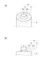
- FIG. 1 is a perspective view of the backing member shown in FIG. 1
- FIG. 2A is a side view of the backing member shown in (A).
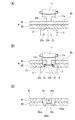
- FIGS. 2A to 2C are cross-sectional views illustrating a joining procedure by the friction stir spot welding apparatus shown in FIG.
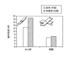
- the joint strength of the joint structure joined by the friction stir spot welding device (backing member: convex surface) shown in FIG. 1 and the joint strength of the joint structure joined by the conventional friction stir spot welding device (backing member: flat surface) 6 is a graph showing an experimental result in comparison with FIG. It is a graph of the experimental result which shows the relationship between the tip diameter of the backing member which has a convex surface, and joint strength. It is a graph of the experimental result which shows the relationship between the taper angle of the backing member which has a convex surface, and joint strength.
- FIG. 1 is a configuration diagram of the friction stir spot welding device 1 according to the embodiment.
- the work W is a pair of plate materials W1 and W2 superposed on each other, and is made of, for example, a steel material.
- the friction stir spot welding apparatus 1 spot-welds the overlapped portion Wa of the pair of plate materials W1 and W2.
- the friction stir spot welding apparatus 1 includes a base 2, a movable body 3 attached to the base 2, and a tool holder 4 projecting from the movable body 3 toward the workpiece W.
- the movable body 3 is attached to the base 2 so as to be slidable along the axis of the tool holder 4.
- the tool holder 4 is configured to be rotatable around its axis, and a tool 11 is detachably attached to the tip of the tool holder 4.
- the tool 11 includes a shoulder portion 11a having a flat annular surface facing the workpiece W, and a cylindrical pin portion 11b continuously projecting from the center of the shoulder portion 11a toward the workpiece W on the inner diameter side of the shoulder portion 11a. (See FIG. 3A). Note that the side peripheral surface of the pin portion 11b is slightly tapered.
- a curved frame 5 having a substantially L-shape is fixed to the base 2. The curved frame 5 extends to a position where the tip end faces the tool 11.
- a backing member 6 that supports the back surface of the overlapped portion Wa of the workpiece W from the side opposite to the tool 11 is provided at the distal end of the curved frame 5.
- the base 2 is provided with a linear motion driver 7 for slidingly displacing the movable body 3 in the axial direction of the tool holder 4.
- the linear motion driver 7 displaces the tool 11 with respect to the workpiece W by sliding the movable body 3.
- the movable body 3 is provided with a rotation driver 8 for rotating the tool holder 4 around its axis.
- the rotation driver 8 rotates the tool 11 by rotating the tool holder 4.
- An articulated robot 9 is attached to the base 2.
- the articulated robot 9 displaces the tool 11 to a desired position with respect to the workpiece W by displacing the base 2. That is, the linear motion driver 7 and the articulated robot 9 serve as a displacement driver 10 for relatively displacing the workpiece W and the tool 11 with each other.
- the friction stir spot welding apparatus 1 includes a linear drive 7, a rotary drive 8, and a controller 12 for controlling the articulated robot 9.
- the controller 12 may have a configuration in which functions are integrated in one control unit, or may have a configuration in which functions are distributed to a plurality of control units.
- the controller 12 has a processor, a volatile memory, a nonvolatile memory, an I / O interface, and the like.
- the controller 12 responds to a command input from an input device (not shown) (e.g., a computer or a teaching pendant) via the I / O interface, and based on a control program stored in a non-volatile memory, the processor operates in a volatile memory. And communicates with the rotation driver 8 and the displacement driver 10 via the I / O interface.
- the friction stir spot welding apparatus 1 pushes the tool 11 into the overlapping portion Wa of the pair of plate materials W1 and W2 while rotating the tool 11 to overlap.
- the portion softened by the frictional heat in the portion Wa is stirred and plastically fluidized, and friction stir spot welding is performed.
- the backing member 6 includes a support surface 20 that comes into contact with the back surface of the overlapping portion Wa of the work W.
- the support surface 20 has a base surface 21 having a flat annular surface facing the work W, and protrudes from the center of the base surface 21 toward the overlapped portion Wa of the work W continuously from the inner diameter side of the base surface 21.
- a convex surface 22 faces the base surface 21 faces the shoulder portion 11a of the tool 11 (FIG. 3A).
- the convex surface 22 faces the pin portion 11b of the tool 11 (FIG. 3A). That is, the convex surface 22 has a smaller diameter than the shoulder portion 11 a of the tool 11.
- the convex surface 22 is, for example, a smooth surface.
- the height (projection amount) of the convex surface 22 of the backing member 6 is smaller than the height (projection amount) of the pin portion 11 b of the tool 11.
- the height of the convex surface 22 of the backing member 6 is smaller than the thickness of the plate material Wb with which the backing member 6 contacts.
- the convex surface 22 has a trapezoidal vertical cross section.
- the side peripheral surface 22a of the convex surface 22 has a normal line obliquely inclined outward in the radial direction of the convex surface 22 with respect to the normal line of the base surface 21.
- the side peripheral surface 22a of the convex surface 22 has a tapered conical shape.
- the side peripheral surface 22a is inclined with the taper angle ⁇ with respect to the base surface 21.
- the tip surface 22b of the convex surface 22 is a flat surface.
- the distal end face 22b has a circular shape having a predetermined distal diameter D1.
- the tip surface 22b is parallel to the back surface of the overlapping portion Wa of the workpiece W, and is parallel to the tip surface of the pin portion 11b of the tool 11.
- FIGS. 3A to 3C are cross-sectional views illustrating a joining procedure by the friction stir spot welding apparatus 1 shown in FIG.
- the convex surface 22 of the support surface 20 of the backing member 6 is brought into contact with the back surface of the overlapping portion Wa of the pair of plate members W1 and W2.
- the base surface 21 of the support surface 20 of the backing member 6 is separated from the overlapping portion Wa.
- the controller 12 controls the rotation driver 8 to rotate the tool 11.
- the controller 12 sets the pin at a position where the center of the pin portion 11b of the tool 11 matches the center of the convex surface 22 of the backing member 6 in plan view (when viewed from the normal direction of the overlapping portion Wa).
- the linear motion driver 7 is controlled so that the portion 11b is pushed into the overlapping portion Wa.
- the overlapping portion Wa of the work W is softened by frictional heat due to the rotational force and the pressing force of the tool 11, and the softened portion is stirred and plastically flows.
- a central portion Fa sandwiched between the pin portion 11b of the tool 11 and the convex surface 22 of the backing member 6 in the plastic flow region F of the overlapped portion Wa, and a shoulder portion 11a of the tool 11 And an outer peripheral portion Fb sandwiched between the base member 21 and the backing member 6.
- the convex surface 22 of the backing member 6 is pushed into the plastic flow region F so as to form a concave portion having a smaller diameter than the plastic flow region F on the back surface of the overlapping portion Wa, and the base surface 21 of the backing member 6 is overlapped. It contacts the back surface of the section Wa.
- the central portion Fa of the plastic flow region F of the overlapped portion Wa which is sandwiched between the pin portion 11b of the tool 11 and the convex surface 22 of the backing member 6, becomes thin, and the diameter of the plastic flow region F increases.
- the side peripheral surface 22a of the convex surface 22 of the backing member 6 is a tapered surface, the plastic flow region F caused by friction stirring gradually increases from the back surface of the overlapped portion Wa toward the boundary surface between the plate materials Wa and Wb. It is easy to incline so that the diameter increases. Accordingly, the diameter of the plastic flow region F due to frictional stirring is intensively increased near the boundary between the plate materials Wa and Wb.
- the front end surface of the convex surface 22 of the backing member 6 is a flat surface, and the central portion Fa of the plastic flow region F between the pin portion 11b of the tool 11 and the front end surface of the convex surface 22 of the backing member 6 is uniform. As a result, the friction energy due to friction stirring is spread outward in the radial direction.
- the controller 12 controls the linear motion driver 7 so as to pull out the tool 11 from the overlapping portion Wa. Then, the plastic flow region F of the overlapped portion Wa is cooled and hardened, and the joint structure W 'in which the friction stir spot joining portion 30 is formed is completed. Specifically, in the friction stir spot joining portion 30 of the joint structure W ′, the plate material W1 and W2 are formed on one surface side, and a concave portion 30a having a diameter smaller than the joining diameter D2 and the plate material on the other surface side are formed. Of the W1 and W2, a concave portion 30b is formed in the plate material Wb on the other surface side to face the concave portion 30a and has a smaller diameter than the joint diameter D2.
- the concave portion 30b has a side peripheral surface 30ba (tapered side peripheral surface) having a normal line obliquely inclined outward in the radial direction of the concave portion 30b with respect to a normal line of the boundary surface between the plate members W1 and W2. It has a bottom surface 30aa parallel to the bottom surface 30aa of the depression 30a.
- the joining diameter D2 is the diameter of the joining region between the plate materials W1 and W2 on the boundary surface between the plate materials W1 and W2.
- the portion sandwiched between the pin portion 11b of the tool 11 and the convex surface 22 of the backing member 6 in the overlapped portion Wa of the plate materials W1 and W2 becomes thin, and the joining diameter D2 becomes smaller. Because of the increase, the joint strength is improved. In addition, it is not necessary to increase the protruding length of the pin portion 11b of the tool 11, and it is not necessary to increase the pressing force or the joining time of the tool 11, so that the life of the tool 11 and the working time can be prevented from being shortened.
- the plastic flow region F due to friction stirring is intensively increased near the boundary between the plate materials W1 and W2, and the joining diameter D2 Can be effectively increased.
- the front end surface 22b of the convex surface 22 of the backing member 6 is flat, the central portion Fa of the plastic flow region F is uniformly thinned, and the radial spread of friction energy is promoted.
- the joint diameter D2 can be effectively increased.
- FIG. 4 shows the joint strength of the joint structure joined by the friction stir spot welding device 1 (backing member: convex surface) shown in FIG. 1 and the joint by the conventional friction stir spot welding device (backing member: flat surface). It is a graph which shows the experimental result which compared the joint strength of the joint structure. Note that a 980 MPa class steel plate (1.2 mmt) was used as a plate material to be joined. The protruding length of the pin portion of the tool was 2.4 mm, and the tip diameter of the pin portion of the tool was 5 mm. In the friction stir spot welding device 1 of the embodiment, the tip diameter D1 of the convex surface 22 of the backing member 6 was set to 5 mm.
- the taper angle of the side peripheral surface 22a of the convex surface 22 of the backing member 6 was set to 26.6 °.
- the support surface of the backing member is flat (no convex surface), and the other welding conditions are that the friction stir spot welding apparatus 1 according to the embodiment is the same as the conventional friction stir spot welding apparatus. Are the same as each other.
- the joint structure (see FIG. 3C) joined by using the friction stir spot joining apparatus 1 of the embodiment has the conventional friction stir point. It was confirmed that the joint strength was higher than that of the joint structure joined using the joining device.
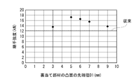
- FIG. 5 is a graph of an experimental result showing the relationship between the tip diameter D1 of the backing member 6 having the convex surface 22 and the joint strength (shear strength).
- Five types of backing members 6 were prepared in which the tip diameter D1 of the convex surface 22 was 3 mm, 5 mm, 6 mm, 7 mm, and 9 mm.
- the tip diameter of the pin portion 11b of the tool 11 was fixed at 5 mm. That is, the ratio of the tip diameter D1 of the convex surface 22 of the backing member 6 to the tip diameter of the pin portion 11b of the tool 11 is five types of 0.6, 1.0, 1.2, 1.4, and 1.8. is there. All other joining conditions are the same. As shown in FIG.
- the joint strength is 12.7 kN, but when the convex backing member 6 is used, In each of the five types, higher joint strength than the conventional one was obtained. That is, when the ratio of [the tip diameter of the convex surface of the backing member] / [the tip diameter of the pin portion of the tool] is 0.6 or more and 1.8 or less, improvement in joint strength was confirmed.
- FIG. 6 is a graph of an experimental result showing the relationship between the taper angle ⁇ of the backing member 6 having the convex surface 22 and the joint strength (shear strength).
- the backing member 6 has five types of taper angles ⁇ of the side peripheral surface 22a of the convex surface 22 of 0.0 °, 14.0 °, 26.6 °, 45.0 °, and 68.2 °. Prepared.
- a taper angle ⁇ of 0.0 ° refers to a conventional backing member having no flat support surface (no taper). All other joining conditions are the same.
- a higher joint strength (shear strength) was obtained in any of the backing members 6 in which the side surface 22a of the convex surface 22 was tapered.
- the present invention is not limited to the above-described embodiment, and the configuration thereof can be changed, added, or deleted.
- the side peripheral surface 22a of the convex surface 22 of the backing member 6 may have a shape that tapers in an arc shape instead of a straight taper shape in a longitudinal sectional view.
- the distal end surface 22b of the convex surface 22 of the backing member 6 may be a non-flat surface, for example, an arc surface that is convex in the direction in which the convex surface 22 projects.
- the entire convex surface 22 of the backing member 6 may be arc-shaped.
Landscapes
- Engineering & Computer Science (AREA)
- Mechanical Engineering (AREA)
- Physics & Mathematics (AREA)
- Optics & Photonics (AREA)
- Pressure Welding/Diffusion-Bonding (AREA)
Abstract
Priority Applications (3)
| Application Number | Priority Date | Filing Date | Title |
|---|---|---|---|
| KR1020217002226A KR102433338B1 (ko) | 2018-07-03 | 2018-07-03 | 마찰 교반 점 접합 장치의 받침 부재, 마찰 교반 점 접합 장치, 마찰 교반 점 접합 방법 및 이음새 구조 |
| PCT/JP2018/025130 WO2020008512A1 (fr) | 2018-07-03 | 2018-07-03 | Élément de support pour dispositif de soudage par points par friction-malaxage, dispositif de soudage par points par friction-malaxage, procédé de soudage par points par friction-malaxage, et structure d'articulation |
| CN201880094784.5A CN112351857A (zh) | 2018-07-03 | 2018-07-03 | 摩擦搅拌点接合装置的衬垫部件、摩擦搅拌点接合装置、摩擦搅拌点接合方法以及接头构造 |
Applications Claiming Priority (1)
| Application Number | Priority Date | Filing Date | Title |
|---|---|---|---|
| PCT/JP2018/025130 WO2020008512A1 (fr) | 2018-07-03 | 2018-07-03 | Élément de support pour dispositif de soudage par points par friction-malaxage, dispositif de soudage par points par friction-malaxage, procédé de soudage par points par friction-malaxage, et structure d'articulation |
Publications (1)
| Publication Number | Publication Date |
|---|---|
| WO2020008512A1 true WO2020008512A1 (fr) | 2020-01-09 |
Family
ID=69059437
Family Applications (1)
| Application Number | Title | Priority Date | Filing Date |
|---|---|---|---|
| PCT/JP2018/025130 Ceased WO2020008512A1 (fr) | 2018-07-03 | 2018-07-03 | Élément de support pour dispositif de soudage par points par friction-malaxage, dispositif de soudage par points par friction-malaxage, procédé de soudage par points par friction-malaxage, et structure d'articulation |
Country Status (3)
| Country | Link |
|---|---|
| KR (1) | KR102433338B1 (fr) |
| CN (1) | CN112351857A (fr) |
| WO (1) | WO2020008512A1 (fr) |
Citations (3)
| Publication number | Priority date | Publication date | Assignee | Title |
|---|---|---|---|---|
| JP4172343B2 (ja) * | 2003-07-03 | 2008-10-29 | マツダ株式会社 | 摩擦スポット接合方法 |
| WO2011024320A1 (fr) * | 2009-08-31 | 2011-03-03 | 三菱日立製鉄機械株式会社 | Procédé de liaison par friction-malaxage sur les deux faces, dispositif de liaison, procédé de liaison de plaques métalliques dans une installation de laminage à froid, et installation de laminage à froid |
| JP4671523B2 (ja) * | 2001-03-29 | 2011-04-20 | マツダ株式会社 | 摩擦撹拌を用いた加工管理方法及び加工管理装置 |
Family Cites Families (6)
| Publication number | Priority date | Publication date | Assignee | Title |
|---|---|---|---|---|
| JP3681156B2 (ja) | 2000-05-10 | 2005-08-10 | 住友軽金属工業株式会社 | 点接合継ぎ手及び点接合方法 |
| CN1257036C (zh) * | 2001-03-29 | 2006-05-24 | 马自达汽车株式会社 | 利用摩擦搅动的连接方法及设备 |
| JP4218888B2 (ja) * | 2004-01-26 | 2009-02-04 | Obara株式会社 | C型摩擦撹拌スポット接合ガン |
| WO2005089998A1 (fr) * | 2004-03-19 | 2005-09-29 | Hitachi, Ltd. | Procédé et appareil de soudage par points par agitation friction |
| JP4507743B2 (ja) * | 2004-07-27 | 2010-07-21 | マツダ株式会社 | 摩擦接合方法およびその装置 |
| JP4453506B2 (ja) * | 2004-09-30 | 2010-04-21 | マツダ株式会社 | 摩擦点接合方法 |
-
2018
- 2018-07-03 WO PCT/JP2018/025130 patent/WO2020008512A1/fr not_active Ceased
- 2018-07-03 KR KR1020217002226A patent/KR102433338B1/ko active Active
- 2018-07-03 CN CN201880094784.5A patent/CN112351857A/zh active Pending
Patent Citations (3)
| Publication number | Priority date | Publication date | Assignee | Title |
|---|---|---|---|---|
| JP4671523B2 (ja) * | 2001-03-29 | 2011-04-20 | マツダ株式会社 | 摩擦撹拌を用いた加工管理方法及び加工管理装置 |
| JP4172343B2 (ja) * | 2003-07-03 | 2008-10-29 | マツダ株式会社 | 摩擦スポット接合方法 |
| WO2011024320A1 (fr) * | 2009-08-31 | 2011-03-03 | 三菱日立製鉄機械株式会社 | Procédé de liaison par friction-malaxage sur les deux faces, dispositif de liaison, procédé de liaison de plaques métalliques dans une installation de laminage à froid, et installation de laminage à froid |
Also Published As
| Publication number | Publication date |
|---|---|
| CN112351857A (zh) | 2021-02-09 |
| KR102433338B1 (ko) | 2022-08-18 |
| KR20210024072A (ko) | 2021-03-04 |
Similar Documents
| Publication | Publication Date | Title |
|---|---|---|
| JP7216551B2 (ja) | 摩擦攪拌点接合装置及び摩擦攪拌点接合方法 | |
| CN111050977B (zh) | 复动式摩擦搅拌点接合方法、按压工具组件以及复动式摩擦搅拌点接合装置 | |
| KR100671637B1 (ko) | 접합 방법 및 접합 장치 | |
| JP4404052B2 (ja) | 摩擦攪拌接合方法 | |
| JP5854451B2 (ja) | 異種金属板の接合方法 | |
| CN109070264B (zh) | 点接合装置、点接合方法及接头结构 | |
| US11179799B2 (en) | Clamp member for double-acting friction stir spot welding device, double-acting friction stir spot welding device, and double-acting friction stir spot welding method | |
| JP2004148320A (ja) | 摩擦撹拌を用いた接合方法及び接合用工具 | |
| US12496655B2 (en) | Friction stir joining device, method of operating the same and joint structure | |
| JP7101140B2 (ja) | 摩擦撹拌接合用工具 | |
| CN113747992A (zh) | 用于摩擦搅拌焊接的工具和用于制造面板的方法 | |
| WO2021002211A1 (fr) | Système d'assemblage et procédé d'actionnement associé | |
| JP6969888B2 (ja) | 摩擦撹拌点接合装置の裏当て部材、摩擦撹拌点接合装置及び摩擦撹拌点接合方法 | |
| JP3452044B2 (ja) | 摩擦攪拌ツールおよびこれを用いた接合方法ならびに鋳物表面の微細空隙除去方法 | |
| JP2003053586A (ja) | 溶接継手の溶接ビード整形方法及び溶接継手 | |
| WO2005089998A1 (fr) | Procédé et appareil de soudage par points par agitation friction | |
| KR102433338B1 (ko) | 마찰 교반 점 접합 장치의 받침 부재, 마찰 교반 점 접합 장치, 마찰 교반 점 접합 방법 및 이음새 구조 | |
| JP7083771B2 (ja) | 摩擦撹拌接合用工具 | |
| JP2021062409A (ja) | 摩擦攪拌点接合装置及びその運転方法 | |
| JP2008254012A (ja) | スポット接合装置及びスポット接合方法 | |
| JP2007054885A (ja) | 接合ツールおよび摩擦撹拌接合方法 | |
| JP7141359B2 (ja) | 摩擦撹拌接合用工具 | |
| JP2018001247A (ja) | 摩擦攪拌点接合装置及びその運転方法 | |
| JP7615873B2 (ja) | 金属部材の接合装置および接合方法 | |
| JP2004337890A (ja) | 摩擦攪拌接合装置 |
Legal Events
| Date | Code | Title | Description |
|---|---|---|---|
| 121 | Ep: the epo has been informed by wipo that ep was designated in this application |
Ref document number: 18925617 Country of ref document: EP Kind code of ref document: A1 |
|
| NENP | Non-entry into the national phase |
Ref country code: DE |
|
| ENP | Entry into the national phase |
Ref document number: 20217002226 Country of ref document: KR Kind code of ref document: A |
|
| 122 | Ep: pct application non-entry in european phase |
Ref document number: 18925617 Country of ref document: EP Kind code of ref document: A1 |
|
| NENP | Non-entry into the national phase |
Ref country code: JP |