WO2020008536A1 - Dispositif de détection d'obstacle - Google Patents
Dispositif de détection d'obstacle Download PDFInfo
- Publication number
- WO2020008536A1 WO2020008536A1 PCT/JP2018/025257 JP2018025257W WO2020008536A1 WO 2020008536 A1 WO2020008536 A1 WO 2020008536A1 JP 2018025257 W JP2018025257 W JP 2018025257W WO 2020008536 A1 WO2020008536 A1 WO 2020008536A1
- Authority
- WO
- WIPO (PCT)
- Prior art keywords
- obstacle
- vehicle
- value
- distance
- unit
- Prior art date
- Legal status (The legal status is an assumption and is not a legal conclusion. Google has not performed a legal analysis and makes no representation as to the accuracy of the status listed.)
- Ceased
Links
Images












Classifications
-
- G—PHYSICS
- G01—MEASURING; TESTING
- G01S—RADIO DIRECTION-FINDING; RADIO NAVIGATION; DETERMINING DISTANCE OR VELOCITY BY USE OF RADIO WAVES; LOCATING OR PRESENCE-DETECTING BY USE OF THE REFLECTION OR RERADIATION OF RADIO WAVES; ANALOGOUS ARRANGEMENTS USING OTHER WAVES
- G01S13/00—Systems using the reflection or reradiation of radio waves, e.g. radar systems; Analogous systems using reflection or reradiation of waves whose nature or wavelength is irrelevant or unspecified
- G01S13/88—Radar or analogous systems specially adapted for specific applications
- G01S13/93—Radar or analogous systems specially adapted for specific applications for anti-collision purposes
-
- G—PHYSICS
- G01—MEASURING; TESTING
- G01S—RADIO DIRECTION-FINDING; RADIO NAVIGATION; DETERMINING DISTANCE OR VELOCITY BY USE OF RADIO WAVES; LOCATING OR PRESENCE-DETECTING BY USE OF THE REFLECTION OR RERADIATION OF RADIO WAVES; ANALOGOUS ARRANGEMENTS USING OTHER WAVES
- G01S7/00—Details of systems according to groups G01S13/00, G01S15/00, G01S17/00
- G01S7/02—Details of systems according to groups G01S13/00, G01S15/00, G01S17/00 of systems according to group G01S13/00
- G01S7/41—Details of systems according to groups G01S13/00, G01S15/00, G01S17/00 of systems according to group G01S13/00 using analysis of echo signal for target characterisation; Target signature; Target cross-section
Definitions
- the present invention relates to an obstacle detection device.
- Patent Document 1 when the height of the obstacle is low, the vehicle approaches the obstacle and the obstacle moves out of the detection area of the distance measurement sensor (that is, the peak value of the reflected wave decreases). ) Is used to determine the height of the obstacle. For this reason, the prior art described in Patent Literature 1 has a problem in that it is not possible to determine the height of a distant obstacle. Further, the conventional technique described in Patent Document 1 has a problem that when the distance between the vehicle and the obstacle is constant, the height of the obstacle cannot be determined.
- Patent Document 2 determines the relative height of an obstacle with respect to a predetermined height by comparing the peak value of a reflected wave with a reference value. This utilizes the fact that the peak value differs depending on the height of the obstacle.
- Patent Literature 1 when an obstacle is located far away, the difference in peak value according to the height of the obstacle becomes small. For this reason, the prior art described in Patent Literature 2 has a problem in that the accuracy of determining the height of a distant obstacle is low.
- Patent Document 2 when an obstacle has a height approximately equal to a predetermined height, an error in determining the height of the obstacle relative to the predetermined height is likely to occur. There was a problem.
- the present invention has been made to solve the above-described problem, and has as its object to accurately determine the height of an obstacle using a distance measurement sensor.
- An obstacle detection device includes a feature amount extraction unit that extracts a feature amount related to a plurality of reflected waves when a distance measurement sensor provided in the vehicle receives a plurality of reflected waves due to an obstacle; An obstacle determining unit that determines that the height of the obstacle is higher when the amount of variance is larger than when the amount of variance is smaller, the first parameter value indicating the size of the feature amount, and the size of the amount of variance An obstacle determining unit that determines whether or not the obstacle is a traveling obstacle based on the result of the clustering of the second parameter value indicating the second parameter value. Is a quantity based on the distance value of.
- the configuration is as described above, it is possible to accurately determine the height of the obstacle using the distance measuring sensor.
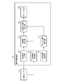
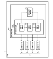
- FIG. 2 is a block diagram illustrating a main part of the obstacle detection device according to the first embodiment.
- FIG. 3 is a block diagram illustrating a main part of an obstacle detection unit in the obstacle detection device according to the first embodiment.
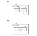
- FIG. 3A is an explanatory diagram illustrating a hardware configuration of the obstacle detection device according to the first embodiment.
- FIG. 3B is an explanatory diagram illustrating another hardware configuration of the obstacle detection device according to the first embodiment.
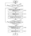
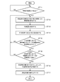
- 5 is a flowchart illustrating an operation of the obstacle detection device according to the first embodiment.
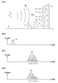
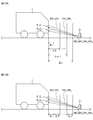
- FIG. 5A is an explanatory diagram illustrating an example of a propagation path of a reflected wave by a traveling obstacle.
- FIG. 5B is an explanatory diagram illustrating an example of a waveform of a transmission signal.
- FIG. 5A is an explanatory diagram illustrating an example of a propagation path of a reflected wave by a traveling obstacle.
- FIG. 5B is an explanatory diagram illustrating an example of a waveform
- FIG. 5C is an explanatory diagram illustrating an example of a waveform of a reception signal corresponding to a reflected wave due to a traveling obstacle.
- FIG. 5D is an explanatory diagram illustrating another example of the waveform of the received signal corresponding to the reflected wave from the traveling obstacle.
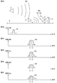
- FIG. 6A is an explanatory diagram illustrating an example of a propagation path of a reflected wave due to a road obstacle or a road surface obstacle.
- FIG. 6B is an explanatory diagram illustrating an example of a waveform of a transmission signal.
- FIG. 6C is an explanatory diagram illustrating an example of a waveform of a received signal corresponding to a reflected wave from a road obstacle.
- FIG. 6D is an explanatory diagram showing another example of the waveform of the received signal corresponding to the reflected wave from the road obstacle.
- FIG. 6E is an explanatory diagram illustrating an example of a waveform of a reception signal corresponding to a reflected wave from a road surface obstacle.
- FIG. 6F is an explanatory diagram illustrating another example of the waveform of the received signal corresponding to the reflected wave due to the road surface obstacle.
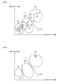
- FIG. 7A is an explanatory diagram illustrating an example of actually measured first parameter values and second parameter values before manufacturing the obstacle detection device according to Embodiment 1.
- FIG. 7B is an explanatory diagram illustrating an example of the first parameter value and the second parameter value calculated after shipping of the vehicle including the obstacle detection device according to Embodiment 1.
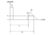
- FIG. 9 is an explanatory diagram illustrating an example of a propagation time used for calculating a distance value.
- FIG. 9 is an explanatory diagram illustrating an example of a propagation time used for calculating a distance value.
- FIG. 9 is a block diagram showing a main part of a driving support device according to Embodiment 2.
- 9 is a flowchart showing the operation of the driving support device according to Embodiment 2.
- FIG. 12A is an explanatory diagram showing an example of an installation position of a distance measuring sensor in a vehicle, and is an explanatory diagram showing a state viewed from above the vehicle.
- FIG. 12A is an explanatory diagram showing an example of an installation position of a distance measuring sensor in a vehicle, and is an explanatory diagram showing a state viewed from above the vehicle.
- FIG. 12B is an explanatory diagram illustrating an example of an installation position of the distance measurement sensor in the vehicle, and is an explanatory diagram illustrating a state viewed from a side of the vehicle.
- FIG. 13A is an explanatory diagram showing an example of an installation position of a distance measurement sensor in a vehicle, and is an explanatory diagram showing a state viewed from above the vehicle.
- FIG. 13B is an explanatory diagram illustrating an example of an installation position of the distance measurement sensor in the vehicle, and is an explanatory diagram illustrating a state viewed from a side of the vehicle. It is explanatory drawing which shows the example of a facing angle.
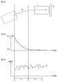
- FIG. 15A is an explanatory diagram illustrating an example of a traveling route when the vehicle approaches an obstacle.
- FIG. 15A is an explanatory diagram illustrating an example of a traveling route when the vehicle approaches an obstacle.
- FIG. 15B is an explanatory diagram showing an example of a temporal change of the directly facing angle at this time.
- FIG. 15C is an explanatory diagram illustrating an example of data indicating the feature amount at this time.
- FIG. 13 is a block diagram illustrating a main part of another driving support device according to Embodiment 2.
- 9 is a flowchart showing an operation of another driving support device according to Embodiment 2.
- FIG. 18A is an explanatory diagram illustrating an example of a detection section.
- FIG. 18B is an explanatory diagram illustrating another example of the detection section.
- 9 is a flowchart illustrating another operation of the driving support device according to the second embodiment.
- FIG. 20A is an explanatory diagram illustrating another example of the installation position of the distance measurement sensor in the vehicle, and is an explanatory diagram illustrating a state viewed from above the vehicle.
- FIG. 20B is an explanatory diagram illustrating another example of the installation position of the distance measurement sensor in the vehicle, and is an explanatory diagram illustrating a state viewed from a side of the vehicle.
- FIG. 21A is an explanatory diagram illustrating another example of the installation position of the distance measurement sensor in the vehicle, and is an explanatory diagram illustrating a state viewed from above the vehicle.
- FIG. 21B is an explanatory diagram illustrating another example of the installation position of the distance measurement sensor in the vehicle, and is an explanatory diagram illustrating a state viewed from a side of the vehicle.
- FIG. 9 is a block diagram showing a main part of a driving support device according to Embodiment 3.
- 9 is a flowchart showing the operation of the driving support device according to Embodiment 3.
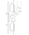
- FIG. 14 is an explanatory diagram showing an example of a detection result by an obstacle detection unit in the driving support device according to Embodiment 3. It is explanatory drawing which shows the example of a parking position and a guidance route. It is explanatory drawing which shows other examples of a parking position and a guidance route. It is explanatory drawing which shows other examples of a parking position and a guidance route.
- FIG. 9 is a block diagram showing a main part of a driving support device according to Embodiment 3.
- 9 is a flowchart showing the operation of the driving support device according to Embodiment 3.
- FIG. 14 is an explanatory diagram showing an example of a detection result by an obstacle detection unit in the driving support device according to Embodiment 3.
- It is explanatory drawing which shows the example of a parking position
- FIG. 14 is a block diagram showing a main part of a driving support device according to Embodiment 4.
- FIG. 30A is an explanatory diagram illustrating an example of a measurement distance and a movement distance.
- FIG. 30B is an explanatory diagram illustrating another example of the measurement distance and the movement distance.
- FIG. 31A is an explanatory diagram illustrating an example of actually measured first parameter values and second parameter values before manufacturing the obstacle detection device according to Embodiment 4.
- FIG. 31B is an explanatory diagram illustrating an example of the first parameter value and the second parameter value calculated after shipping of the vehicle having the obstacle detection device according to Embodiment 4.
- 9 is a flowchart showing the operation of the driving support device according to Embodiment 4.
- FIG. 1 is a block diagram illustrating a main part of the obstacle detection device according to the first embodiment.
- FIG. 2 is a block diagram illustrating a main part of an obstacle detection unit in the obstacle detection device according to the first embodiment.
- an obstacle detection device 100 according to the first embodiment will be described.
- the obstacle detection device 100 is connected to a computer network (for example, CAN (Controller Area Network)) in the vehicle 1.
- the obstacle detection device 100 can appropriately acquire various signals from the computer network. These signals include, for example, a signal indicating the traveling speed of the vehicle 1 and a signal indicating the yaw rate or the steering angle of the vehicle 1.
- the vehicle 1 has a distance measuring sensor 2.
- the distance measuring sensor 2 includes N distance measuring sensors 2 1 to 2 N (N is an arbitrary integer of 2 or more).
- the N distance measuring sensors 2 1 to 2 N have different installation positions in the vehicle 1 and have the same installation direction in the vehicle 1.
- Each of the N distance measuring sensors 2 1 to 2 N is constituted by, for example, a sonar or a millimeter-wave radar.
- search waves ultrasonic waves or radio waves transmitted and received by the distance measuring sensor 2
- search waves When the search wave is reflected by an obstacle outside the vehicle 1, the reflected search wave is referred to as a "reflected wave”.
- the search wave and the reflected wave are referred to as “direct waves”.
- the search wave and the reflected wave are referred to as “indirect waves”.
- the traveling obstacle is, for example, a wall or another parked vehicle (hereinafter, referred to as “parked vehicle”).
- parked vehicle obstacles having a height low enough not to contact the bumper portion of the vehicle 1 and having a height high enough not to be able to get over the vehicle 1
- road obstacles obstacles having a height low enough not to contact the bumper portion of the vehicle 1 and having a height high enough not to be able to get over the vehicle 1
- the road obstacle is, for example, a curb or a wheelchair.
- an obstacle having a height low enough not to contact the bumper portion of the vehicle 1 and having a height low enough to allow the vehicle 1 to get over is referred to as “road obstacle”. That.
- the road surface obstacle is, for example, a step. That is, the traveling obstacle has a height higher than the road obstacle, and the road obstacle has a height higher than the road obstacle.
- the obstacle detection unit 11 detects an obstacle around the vehicle 1 by causing the distance measurement sensor 2 to transmit a search wave. More specifically, the obstacle detection unit 11 determines the position of the obstacle with respect to the vehicle 1 by measuring the distance between the vehicle 1 and the obstacle.
- the obstacle detection unit 11 includes a transmission signal output unit 21, a reception signal acquisition unit 22, a distance value calculation unit 23, a reflection point position calculation unit 24, a grouping unit 25, a vehicle position calculation unit 26, and a sensor position calculation unit 27. It is configured.
- the transmission signal output section 21 outputs a transmission signal to the distance measurement sensor 2 so that the distance measurement sensor 2 transmits a search wave.
- the reception signal acquisition unit 22 acquires a reception signal from the distance measurement sensor 2 from the distance measurement sensor 2.
- the distance value calculation unit 23 determines whether or not the reflected wave is received by the distance measuring sensor 2 by comparing the intensity of the signal received by the distance measuring sensor 2 with a predetermined threshold value.
- the distance value calculator 23 calculates a distance value by TOF when a reflected wave is received by the distance measuring sensor 2. Since a method of calculating a distance value by TOF is known, detailed description is omitted.
- the reflection point position calculation unit 24 calculates the position of the point where the search wave is reflected (hereinafter referred to as “reflection point”) using the distance value calculated by the distance value calculation unit 23.
- the position of the reflection point is determined by, for example, a first axis (hereinafter referred to as “X axis”) corresponding to the front-rear direction of the vehicle 1 and a second axis (hereinafter referred to as “Y axis”) corresponding to the left / right direction of the vehicle 1. It is represented by coordinate values in a coordinate system in meters (hereinafter referred to as “XY coordinate system”).
- the reflection point position calculation unit 24 calculates the position of the reflection point by a so-called “two-circle intersection” using a plurality of distance values corresponding to mutually different direct waves. That is, the reflection point position calculation unit 24 executes the two-circle intersection processing on a virtual plane (hereinafter, referred to as an “XY plane”) along the X axis and the Y axis, thereby obtaining the coordinate value of the reflection point in the XY coordinate system. Is calculated. In the two-circle intersection processing, information indicating the position of the distance measuring sensor 2 at the transmission timing of the search wave (or the reception timing of the reflected wave) is used. This information is output by the sensor position calculator 27.
- XY plane virtual plane
- the grouping unit 25 groups the plurality of reflection points to correspond to one or more obstacles in principle one-to-one.
- One or more reflection point groups (hereinafter, referred to as “groups”) are set. In this grouping, for example, when the distance between two adjacent reflection points is less than a predetermined distance, the two reflection points are included in the same group.
- the own vehicle position calculating unit 26 calculates the position of the vehicle 1 at the transmission timing of the search wave (or the reception timing of the reflected wave) (hereinafter, referred to as “own vehicle position”).
- the sensor position calculator 27 calculates the position of the distance measuring sensor 2 at the timing (hereinafter, referred to as “sensor position”). These positions are represented by coordinate values in an XY coordinate system, for example.
- the sensor position calculator 27 outputs information indicating the sensor position to the reflection point position calculator 24.
- the information indicating the sensor position is used by the reflection point position calculation unit 24 to calculate the position of the reflection point.
- Various known methods can be used to calculate the vehicle position (for example, autonomous navigation), and a detailed description of these methods will be omitted.
- Signals used for autonomous navigation for example, a signal indicating the traveling speed of the vehicle 1 and a signal indicating the yaw rate or the steering angle of the vehicle 1.
- Information used for calculating the sensor position for example, information indicating the installation position of the distance measurement sensor 2 in the vehicle 1. is stored in the sensor position calculation unit 27 in advance.
- an indirect wave may be used instead of or in addition to the direct wave.
- the number of reflection points obtained by transmitting the search wave each time can be increased as compared with the case where only the direct wave is used. As a result, the number of reflection points included in each group can be increased.
- Each group includes a plurality of reflection points, and the plurality of reflection points correspond to a plurality of reflected waves.
- the feature amount extraction unit 12 acquires information indicating a distance value corresponding to each of the plurality of reflection points from the obstacle detection unit 11. These distance values are calculated by the distance value calculation unit 23. Alternatively, the feature amount extraction unit 12 acquires information indicating the coordinate values of each of the plurality of reflection points from the obstacle detection unit 11. These coordinate values are calculated by the reflection point position calculation unit 24.
- the feature value extraction unit 12 extracts a feature value of the plurality of reflected waves using the acquired information. Details of the feature amount will be described later.
- the obstacle determining unit 13 determines, for each group, a value indicating the magnitude of the feature amount extracted by the feature amount extracting unit 12 (hereinafter referred to as a “first parameter value”. For example, an average value of these feature amounts is used. Is calculated). In addition, the obstacle determining unit 13 determines, for each group, a value indicating the magnitude of the variance of the feature amount extracted by the feature amount extracting unit 12 (hereinafter, referred to as a “second parameter value”. Is the variance of the amount.) The obstacle determining unit 13 determines the type of the obstacle corresponding to each group using the calculated first parameter value and the calculated second parameter value. More specifically, the obstacle determining unit 13 determines whether the obstacle corresponding to each group is a road surface obstacle, a road obstacle, or a running obstacle.
- the road surface obstacle, the road obstacle, and the traveling obstacle have different heights from each other. Therefore, it is determined whether the obstacle corresponding to each group is a road surface obstacle, a road obstacle, or a running obstacle. It is a judgment as to which height it has. That is, the obstacle determining unit 13 determines the height of the obstacle corresponding to each group by determining the type of the obstacle corresponding to each group. The details of the method of determining the type of the obstacle by the obstacle determination unit 13, that is, the method of determining the height of the obstacle will be described later.
- the obstacle detection unit 11, the feature amount extraction unit 12, and the obstacle discrimination unit 13 constitute a main part of the obstacle detection device 100.
- the obstacle detection device 100 is constituted by a computer, and the computer has a processor 31 and a memory 32.
- the memory 32 stores a program for causing the computer to function as the obstacle detection unit 11, the feature amount extraction unit 12, and the obstacle determination unit 13.
- the functions of the obstacle detection unit 11, the feature amount extraction unit 12, and the obstacle determination unit 13 are realized by the processor 31 reading and executing the program stored in the memory 32.
- the obstacle detection device 100 may be configured by a processing circuit 33.
- the functions of the obstacle detection unit 11, the feature amount extraction unit 12, and the obstacle determination unit 13 may be realized by the processing circuit 33.
- the obstacle detection device 100 may include a processor 31, a memory 32, and a processing circuit 33 (not shown).
- some of the functions of the obstacle detection unit 11, the feature amount extraction unit 12, and the obstacle determination unit 13 are realized by the processor 31 and the memory 32, and the remaining functions are realized by the processing circuit 33. It may be something.
- the processor 31 uses, for example, a CPU (Central Processing Unit), a GPU (Graphics Processing Unit), a microprocessor, a microcontroller, or a DSP (Digital Signal Processor).
- a CPU Central Processing Unit
- GPU Graphics Processing Unit
- microprocessor a microcontroller
- DSP Digital Signal Processor
- the memory 32 uses a semiconductor memory or a magnetic disk, for example. More specifically, the memory 32 includes a RAM (Random Access Memory), a ROM (Read Only Memory), a flash memory, an EPROM (Erasable Programmable Read Memory Only), and an EEPROM (Electrical Memory). State @ Drive) or HDD (Hard @ Disk @ Drive) or the like.
- RAM Random Access Memory
- ROM Read Only Memory
- flash memory an EPROM (Erasable Programmable Read Memory Only)
- EEPROM Electrical Memory
- State @ Drive or HDD (Hard @ Disk @ Drive) or the like.
- the processing circuit 33 includes, for example, an ASIC (Application Specific Integrated Circuit), a PLD (Programmable Logic Device), an FPGA (Field-Programmable Gate Array), and a SoC (Sig-Lig- Is used.
- ASIC Application Specific Integrated Circuit
- PLD Programmable Logic Device
- FPGA Field-Programmable Gate Array
- SoC SoC
- step ST1 the obstacle detecting unit 11 detects an obstacle around the vehicle 1 by causing the distance measuring sensor 2 to transmit a search wave. More specifically, the obstacle detection unit 11 determines the position of the obstacle with respect to the vehicle 1 by measuring the distance between the vehicle 1 and the obstacle.
- step ST1 one or more groups corresponding to one or more obstacles in principle one-to-one are set.
- Each group includes a plurality of reflection points, and the plurality of reflection points correspond to a plurality of reflected waves.
- step ST2 the feature amount extraction unit 12 outputs the information indicating the distance value corresponding to each of the plurality of reflection points or the information indicating the coordinate values of each of the plurality of reflection points to the obstacle detection unit. 11
- the feature amount extraction unit 12 extracts feature amounts related to the plurality of reflected waves using the acquired information. Details of the feature amount will be described later.
- the obstacle determining unit 13 calculates a first parameter value and a second parameter value using the feature amount extracted by the feature amount extracting unit 12.
- the obstacle determining unit 13 determines the type of the obstacle corresponding to each group by using the calculated first parameter value and the second parameter value, thereby obtaining the height of the obstacle corresponding to each group.
- Judge. The details of the method of determining the type of the obstacle by the obstacle determination unit 13, that is, the method of determining the height of the obstacle will be described later.
- FIG. 5A shows an example of the propagation path of the reflected wave RW due to a traveling obstacle (more specifically, a wall).
- FIG. 5B shows an example of the waveform of the transmission signal TS.
- FIG. 5C shows an example of the waveform of the reception signal RS corresponding to the reflected wave RW due to the traveling obstacle.
- FIG. 5D illustrates another example of the waveform of the reception signal RS corresponding to the reflected wave RW due to the traveling obstacle.
- FIG. 6A shows an example of a propagation path of the reflected wave RW due to an obstacle on the road (more specifically, a curb) or an obstacle on the road (more specifically, a step).
- FIG. 6B shows an example of the waveform of the transmission signal TS.
- FIG. 6C shows an example of the waveform of the reception signal RS corresponding to the reflected wave RW due to the obstacle on the road.
- FIG. 6D shows another example of the waveform of the received signal RS corresponding to the reflected wave RW due to the obstacle on the road.
- FIG. 6E shows an example of the waveform of the reception signal RS corresponding to the reflected wave RW due to the road surface obstacle.
- FIG. 6F shows another example of the waveform of the received signal RS corresponding to the reflected wave RW due to the road surface obstacle.
- the transmission signal output unit 21 outputs the transmission signal TS to the distance measurement sensor 2 so that the distance measurement sensor 2 transmits the search wave SW.
- the search wave SW propagates in the air while gradually spreading, the propagation path (so-called “path”) from the transmission of the search wave SW by the distance measuring sensor 2 to the reception of the reflected wave RW by the distance measurement sensor 2.
- path there are a plurality. For example, there is a path that is reflected once by the obstacle O and returns to the distance measurement sensor 2. There is also a path that is reflected once by the road R and then reflected once by the obstacle O and returns to the distance measurement sensor 2. These paths include paths having different path lengths.
- the reflected wave RW becomes a composite wave RW due to interference of a plurality of waves rw corresponding to these paths.
- the reception signal RS is a composite signal of a plurality of signals rs corresponding to the plurality of waves rw, that is, a reception signal RS.
- the path changes according to the uneven shape of the road R, the unevenness of the surface of the vehicle 1 that reflects the vibration of the vehicle 1 and the search wave SW on the obstacle O (hereinafter referred to as “reflective surface”), etc.
- the waveform changes, and the waveform of the received signal RS also changes.
- the waveforms of the plurality of reflected waves RW have variations, and the plurality of reflected waves RW Also has a variation in the waveform of the received signal RS corresponding to.
- the area of the reflection surface is larger than when the obstacle O is a road obstacle or a road surface obstacle (see FIG. 6A).
- the reception strength of the reflected wave RW (that is, the strength of the reception signal RS) increases.
- the variation in the waveform of the reflected wave RW increases, and the variation in the waveform of the reception signal RS also increases.
- the area of the reflecting surface portion is smaller than when the obstacle O is an obstacle on the road (see FIGS. 6E and 6F). Since it is large, the reception strength of the reflected wave RW (that is, the strength of the reception signal RS) increases. In addition, since the total number of paths increases and the difference in path length between paths also increases, the variation in the waveform of the reflected wave RW increases, and the variation in the waveform of the reception signal RS also increases.
- the method of calculating the distance value by the distance value calculation unit 23 is as follows. That is, the distance value calculation unit 23 first detects the transmission timing of the search wave SW by the distance measurement sensor 2, then detects the reception timing of the reflected wave RW by the distance measurement sensor 2, and then detects the detected transmission The propagation time of the search wave SW and the reflected wave RW is calculated using the timing and the reception timing, and then the distance value by TOF is calculated using the calculated propagation time.
- the reception timing of the reflected wave RW is detected, for example, when the intensity of the reception signal RS exceeds a predetermined threshold Th (see FIG. 8), that is, based on the intensity of the reception signal RS.
- a predetermined threshold Th see FIG. 8
- the variation in the distance value calculated by the distance value calculating unit 23 becomes larger than when the obstacle O is a road obstacle or a road surface obstacle.
- the dispersion of the coordinate values calculated by the reflection point position calculation unit 24 also increases.
- the variation in the distance value calculated by the distance value calculation unit 23 becomes larger than when the obstacle O is an obstacle on the road, and the reflection point position is changed.
- the dispersion of the coordinate values calculated by the calculation unit 24 also increases.
- the extracted feature value is extracted.
- the dispersion amount of the feature amount has a correlation with the height of the obstacle O. For this reason, it is possible to determine the height of the obstacle O based on the amount of dispersion, such as determining that the height of the obstacle O is higher when the amount of dispersion is larger than when the amount of dispersion is smaller.
- the determination of the height of the obstacle O by the obstacle determination unit 13 is based on this principle.
- the feature amount extraction unit 12 determines, based on the distance values corresponding to the plurality of reflected waves RW, the plurality of reflected waves RW corresponding to the plurality of reflection points included in each group.
- the quantity is extracted as a feature quantity. More specifically, the feature amount extraction unit 12 determines the difference value of the distance value corresponding to each two reflection points (for example, each two reflection points adjacent to each other) among the plurality of reflection points. Extract as quantity. Alternatively, the feature quantity extraction unit 12 calculates a difference value between the coordinate values of two reflection points (for example, two reflection points adjacent to each other) of the plurality of reflection points, that is, a coordinate value based on a two-circle intersection. Is extracted as a feature value.
- These feature amounts are extracted from information indicating the distance value calculated by the distance value calculation unit 23 or information indicating the coordinate values calculated by the reflection point position calculation unit 24. Further, similar feature values can be obtained by using a difference value between the previous measurement value and the current measurement value of each distance measurement value.
- the first parameter value and the second parameter value enable clustering according to the height of the obstacle O, that is, clustering according to the type of the obstacle O.
- FIG. 7 shows an example of the range A1 including the first parameter value and the second parameter value when the obstacle O is a road surface obstacle, and the first parameter value and the second parameter value when the obstacle O is a road obstacle.
- An example of a range A2 including a parameter value and an example of a range A3 including a first parameter value and a second parameter value when the obstacle O is a traveling obstacle are shown.
- a dividing line PL1 between the ranges A1 and A2 corresponds to a determination threshold Th1 for determining whether the obstacle O is a road surface obstacle.
- the dividing line PL2 between the ranges A2 and A3 corresponds to a threshold value Th2 for determining whether or not the obstacle O is a traveling obstacle.
- Each circle in FIG. 7A is an actual measurement value of the first parameter value and the second parameter value before the manufacture of the obstacle detection device 100, and is an example of the actual measurement value when the obstacle O is a road surface obstacle. Yes, it is.
- Each square mark in FIG. 7A is an actual measurement value of the first parameter value and the second parameter value before manufacturing the obstacle detection device 100, and is an example of the actual measurement value when the obstacle O is an on-road obstacle. Yes, it is.
- Each triangle mark in FIG. 7A is an actual measurement value of the first parameter value and the second parameter value before manufacturing the obstacle detection device 100, and is an example of the actual measurement value when the obstacle O is a traveling obstacle. Yes, it is.
- the information indicating the ranges A1 to A3 set by the clustering of these actually measured values more specifically, the information indicating the discrimination thresholds Th1 and Th2 is stored in the obstacle discrimination unit 13 in advance.
- a machine learning technique such as linear discrimination or pattern recognition is used.
- the obstacle determining unit 13 compares the first parameter value and the second parameter value calculated after the manufacture of the vehicle 1 (more specifically, after shipment) with the determination thresholds Th1 and Th2, thereby obtaining the first parameter. It identifies which of the ranges A1 to A3 the value and the second parameter value fall within. Thereby, it is determined whether the obstacle O around the vehicle 1 is a road surface obstacle, a road obstacle, or a traveling obstacle.
- the crosses in FIG. 7B correspond to examples of the first parameter value and the second parameter value calculated after the shipment of the vehicle 1. In this case, since the first parameter value and the second parameter value are included in the range A3, the obstacle O is determined to be a traveling obstacle.
- the distance value calculation unit 23 first detects the transmission timing of the search wave SW by the distance measurement sensor 2, then detects the reception timing of the reflected wave RW by the distance measurement sensor 2, and then detects the detected timing.
- the propagation time of the search wave SW and the reflected wave RW is calculated using the transmission timing and the reception timing thus obtained.
- the reception timing of the reflected wave RW is detected based on the intensity of the received signal RS (that is, the received intensity of the reflected wave RW).
- FIG. 8 shows an example of a waveform of the transmission signal TS corresponding to the search wave SW and an example of a waveform of the reception signal RS corresponding to the reflection wave RW.
- the distance value calculation unit 23 detects the rising timing of the transmission signal TS as the transmission timing of the search wave SW. Further, the distance value calculation unit 23 detects a timing at which the reception signal RS exceeds the threshold Th as a reception timing of the reflected wave RW.
- the threshold Th is a threshold used for determining whether or not the reflected wave RW has been received.
- T1 indicates an example of the propagation time calculated by the distance value calculation unit 23 in this case.
- the distance value calculation unit 23 detects the rising timing of the transmission signal TS as the transmission timing of the search wave SW. Further, the distance value calculation unit 23 detects the timing at which the reception signal RS has reached the peak value PV as the reception timing of the reflected wave RW.
- T2 indicates an example of the propagation time calculated by the distance value calculation unit 23 in this case.
- the distance value calculation unit 23 detects the rising timing of the transmission signal TS as the transmission timing of the search wave SW. Further, the distance value calculation unit 23 detects a timing corresponding to a central portion of a portion of the reception signal RS on the time axis that exceeds the threshold Th as a reception timing of the reflected wave RW.
- T3 indicates an example of the propagation time calculated by the distance value calculation unit 23 in this case.
- the distance value calculation unit 23 detects the rising timing of the transmission signal TS as the transmission timing of the search wave SW. Further, the distance value calculation unit 23 detects a timing at which the reception signal RS falls below the threshold Th as a reception timing of the reflected wave RW.
- T4 indicates an example of the propagation time calculated by the distance value calculation unit 23 in this case.
- the distance value calculation unit 23 may shape the reception signal RS into a pulse shape based on the threshold value Th, and calculate the propagation times T1 and T4 using the shaped pulse signal RS '. That is, the distance value calculating section 23 may detect the rising timing or the falling timing of the pulse signal RS 'as the reception timing of the reflected wave RW.
- FIG. 9 shows an example of the waveform of the pulse signal RS 'and an example of the propagation times T1 and T4.
- the vehicle position calculating unit 26 may calculate the vehicle position by satellite navigation instead of or in addition to autonomous navigation.
- the obstacle detection device 100 may acquire a GNSS signal from a GNSS (Global Navigation Satellite Network) receiver provided in the vehicle 1.
- GNSS Global Navigation Satellite Network
- the second parameter value may be any value that indicates the magnitude of the variance of the feature value, and is not limited to the variance value of the feature value.
- the second parameter value may be a difference value between the maximum value and the minimum value of the feature value, a difference value between the maximum value and the average value of the feature value, or the average value and the minimum value of the feature value. It may be a value difference value.
- the obstacle determining unit 13 may determine whether an obstacle corresponding to each group is a traveling obstacle. That is, when it is determined that the obstacle is not a traveling obstacle, the obstacle determination unit 13 may not determine whether the obstacle is a road surface obstacle or a road obstacle.
- the obstacle determination unit 13 may store information indicating the determination threshold Th2, but may not store information indicating the determination threshold Th1.
- the distance measuring sensor 2 may be configured by one distance measuring sensor 21 instead of the N distance measuring sensors 2 1 to 2 N.
- the plurality of reflection points included in each group may be the one corresponding to the direct wave which is sent multiple times received by one of the distance measuring sensor 2 1.
- the obstacle detection device 100 uses the feature amount relating to a plurality of reflected waves when the distance measurement sensor 2 provided in the vehicle 1 receives the plurality of reflected waves due to the obstacle.
- An obstacle determining unit 13 that determines whether at least the obstacle is a traveling obstacle based on the result of clustering of the first parameter value indicating the degree of dispersion and the second parameter value indicating the magnitude of the variance.
- the feature amount is an amount based on a plurality of distance values corresponding to a plurality of reflected waves.
- the type of the obstacle can be accurately determined, and the height of the obstacle can be accurately determined. Further, it is possible to determine the height of an obstacle located far from the vehicle 1 (more specifically, at a distance of 5 meters or more).
- the feature value is a value obtained by using a difference value between the coordinate values of the two circle intersections by the plurality of distance measurement sensors 2 or a difference value between the distance values by the plurality of distance measurement sensors 2. This makes it unnecessary to correct for a change in the reflectance of the search wave due to an obstacle. Further, it is not necessary to correct the change in the outside temperature. Further, it is not necessary to correct the attenuation amount according to the propagation distance of the search wave.
- FIG. 10 is a block diagram illustrating a main part of the driving support device according to the second embodiment.
- a driving support device 200a according to the second embodiment will be described.
- the same reference numerals are given to the same blocks as the blocks shown in FIG. 1, and the description will be omitted.
- the distance measuring sensor 2 is composed of four distance measuring sensors 2 1 to 2 4.
- Four distance measuring sensors 2 1 to 2 4 the front end of the vehicle 1 is provided on (more specifically, the front bumper unit), and are directed to the front of the vehicle 1.
- the distance measurement sensor 2 does not need to be directed only to the front of the vehicle 1. It can be installed arbitrarily in the direction in which obstacle detection is desired. Since the same applies hereinafter, the details will not be described individually.
- the obstacle detection unit 11 detects an obstacle in front of the vehicle 1 by causing the distance measurement sensor 2 to transmit a search wave at least once when the vehicle 1 is moving forward.
- the internal configuration of the obstacle detection unit 11 is the same as that described in Embodiment 1 with reference to FIG.
- the facing determination unit 14 determines whether or not the distance measuring sensor 2 faces the obstacle. Details of the determination method by the facing determination unit 14 will be described later.
- the obstacle determining unit 13 calculates the first parameter value and the second parameter value using the feature amount in a state in which the distance measurement sensor 2 faces the obstacle (hereinafter, referred to as “facing state”). Has become. More specifically, when the number of accumulated data indicating the feature amount in the directly facing state exceeds a predetermined number, the obstacle determination unit 13 uses the feature amount indicated by these data to determine the first parameter value and the second parameter value. The parameter value is calculated. The obstacle determining unit 13 determines the type of the obstacle using the calculated first parameter value and the calculated second parameter value. That is, the obstacle determining unit 13 determines the type of the obstacle using the feature amount in the directly facing state.
- the driving support control unit 15a controls the vehicle according to the determination result of the position of the obstacle by the obstacle detection unit 11 and the determination result of the type of the obstacle by the obstacle determination unit 13 (that is, the determination result of the height of the obstacle). This is to execute control for avoiding a collision between the vehicle 1 and an obstacle.
- the support control unit 15a executes control to stop the vehicle 1 by operating the brake of the vehicle 1.
- the driving support control unit 15a cancels the execution of the control.
- the driving support control unit 15a executes the control, and determines that the obstacle is a road obstacle. When it is determined, the driving support control unit 15a may cancel the execution of the control.
- the driving support control unit 15a may vary the stop position of the vehicle 1 depending on whether the obstacle in front of the vehicle 1 is a traveling obstacle or a road obstacle. More specifically, the driving support control unit 15a stops the vehicle 1 at a position on the near side when the obstacle is a traveling obstacle compared to when the obstacle is a road obstacle. It may be. That is, when the obstacle is a road obstacle, the driving support control unit 15a positions the front bumper of the vehicle 1 above the obstacle and causes the front tire of the vehicle 1 to substantially contact the obstacle. The vehicle 1 may be stopped at the position.
- driving support control the control in accordance with the determination result of the position of the obstacle by the obstacle detection unit 11 and the determination result of the type of the obstacle by the obstacle determination unit 13 (that is, the determination result of the height of the obstacle) is referred to as “driving support control”.
- the obstacle detection unit 11, the feature amount extraction unit 12, the obstacle determination unit 13, and the facing determination unit 14 constitute a main part of the obstacle detection device 100a.
- the obstacle detection device 100a and the driving support control unit 15a constitute a main part of the driving support device 200a.
- each function of the obstacle detection unit 11, the feature amount extraction unit 12, the obstacle determination unit 13, the facing determination unit 14, and the driving support control unit 15a is realized by the processor 31 and the memory 32. Or may be realized by the processing circuit 33.
- step ST11 the obstacle detection unit 11 determines whether the vehicle 1 is moving forward using a signal indicating the traveling speed of the vehicle 1, a signal indicating the shift position of the vehicle 1, and the like. These signals are appropriately obtained from a computer network in the vehicle 1.
- step ST11 If the vehicle 1 is moving forward (“YES” in step ST11), the obstacle detection unit 11 causes the distance measurement sensor 2 to transmit the search wave at least once in step ST12, so that the obstacle detection unit 11 is in front of the vehicle 1. Detect obstacles.
- the distance measurement sensor 2 When the distance measurement sensor 2 is installed toward the rear of the vehicle 1, it can be determined that the vehicle 1 is retreating in step ST11.
- step ST11 can be regarded as the vehicle 1 being forward or backward.
- step ST12 one or more groups corresponding to one or more obstacles in principle one-to-one are set.
- Each group includes a plurality of reflection points, and the plurality of reflection points correspond to a plurality of reflected waves.
- the feature amount extraction unit 12 outputs the information indicating the distance value corresponding to each of the plurality of reflection points or the information indicating the coordinate values of each of the plurality of reflection points to the obstacle detection unit.
- the feature amount extraction unit 12 extracts feature amounts related to the plurality of reflected waves using the acquired information.
- the feature amount extraction unit 12 outputs data indicating the extracted feature amount to the obstacle determination unit 13.
- step ST14 the facing determination unit 14 determines whether or not the distance measuring sensor 2 faces the obstacle. Details of the determination method by the facing determination unit 14 will be described later.
- step ST15 the obstacle determination unit 13 determines whether the number of accumulated data indicating the feature amount in the directly facing state has exceeded a predetermined number.
- the process of the driving support device 200a returns to step ST12, and the search wave is transmitted again.
- the process of the driving support device 200a proceeds to step ST16.
- step ST16 the obstacle determining unit 13 calculates a first parameter value and a second parameter value using the feature amount in the directly facing state.
- the obstacle determining unit 13 determines the type of the obstacle corresponding to each group by using the calculated first parameter value and the second parameter value, thereby obtaining the height of the obstacle corresponding to each group.
- step ST17 the driving support control unit 15a determines the position of the obstacle by the obstacle detection unit 11 and the determination result of the type of the obstacle by the obstacle determination unit 13 (that is, the determination of the height of the obstacle). According to the result, the control for avoiding the collision between the vehicle 1 and the obstacle is executed. That is, the driving support control unit 15a executes the driving support control.
- FIG. 12 and FIG. 13 show examples of the installation positions of the four distance measurement sensors 2 1 to 24 in the vehicle 1. 12 and as shown in FIG. 13, 2, which are arranged more inside the four distance measuring sensors 2 1 to 2 measuring sensor 2 1 two more are located outside of the four, 2 4 number of the distance measuring sensor 2 2, and 2 3, the installation position with respect to the vertical direction of the vehicle 1 (that is, the height direction) may be different from each other.
- FIG. 12 shows propagation paths PP 1 to PP of direct waves transmitted and received by the four distance measurement sensors 2 1 to 24 when the obstacle O is a traveling obstacle (more specifically, a wall). 4, an example of reflection points RP 1 to RP 4 corresponding to these direct waves, and an example of a group G corresponding to the obstacle O are shown.
- FIG. 13 shows transmission / reception by the four distance measuring sensors 2 1 to 24 when the obstacle O is a road obstacle (more specifically, a curb) or a road surface obstacle (more specifically, a step).
- 3 shows examples of direct wave propagation paths PP 1 to PP 4 , examples of reflection points RP 1 to RP 4 corresponding to these direct waves, and an example of a group G corresponding to an obstacle O.
- These distances D 1 and D 4 correspond to the distance values calculated by the distance value calculation unit 23 or the coordinate values (more specifically, the X coordinate values) calculated by the reflection point position calculation unit 24.
- the facing-facing determining unit 14 calculates the facing angle ⁇ of the obstacle O with respect to the distance measuring sensor 2 by the following equation (1).
- FIG. 14 shows an example of the sensor pitch SP, the distances D 1 and D 4, and the directly-facing angle ⁇ .
- the facing determining unit 14 determines that the distance measurement sensor 2 faces the obstacle O.
- the facing angle ⁇ is larger than the predetermined angle ⁇ th, the facing determining unit 14 determines that the distance measurement sensor 2 is not directly facing the obstacle O.
- the calculation of the confronting angle theta it is preferred to use a distance measuring sensor 2 1, 2 4, which is spaced apart from one another via the other of the distance measuring sensor 2 2, 2 3.
- a distance measuring sensor 2 1, 2 4 which is spaced apart from one another via the other of the distance measuring sensor 2 2, 2 3.
- the facing determination unit 14 may calculate the average value of the facing angles ⁇ in a predetermined section. When the calculated average value is equal to or smaller than the predetermined angle ⁇ th, the facing determination unit 14 may determine that the distance measurement sensor 2 faces the obstacle O. Thus, the robustness of the discrimination by the facing discrimination unit 14 can be improved.
- the predetermined section may be a time section or a distance section. That is, this average value may be an average value of the facing angle ⁇ calculated while the vehicle 1 moves for a predetermined time, or the average value of the facing angle ⁇ calculated while the vehicle 1 moves for a predetermined distance. The average value may be used.
- FIG. 15A shows an example of the traveling route TR when the vehicle 1 approaches the obstacle O while moving forward or backward.
- FIG. 15B shows an example of a temporal change of the facing angle ⁇ at this time.
- FIG. 15C shows an example of data indicating the feature amount at this time. That is, each circle in FIG. 15C corresponds to data indicating a feature amount.
- the facing angle ⁇ gradually decreases as shown in FIG. 15B.
- the facing angle ⁇ becomes equal to or smaller than the predetermined angle ⁇ th, and at time t3, the number of accumulated data indicating the feature amount in the facing state exceeds the predetermined number.
- the obstacle determination unit 13 calculates the first parameter value and the second parameter value using the feature amount in the time section ⁇ t2 from time t2 to t3.
- the obstacle determining unit 13 determines the type of the obstacle using the feature amount in the directly facing state, and also determines whether the distance measuring sensor 2 is not directly facing the obstacle O (hereinafter referred to as “non-facing”).
- the type of the obstacle may be determined using the feature amount in “state”). That is, the obstacle determination unit 13 calculates the first parameter value and the second parameter value using the feature amount in the time section ⁇ t2 between the times t2 and t3, and also calculates the feature in the time section ⁇ t1 between the times t1 and t2.
- the first parameter value and the second parameter value may be calculated using the amounts.
- the obstacle determination unit 13 may notify the driving support control unit 15a that the reliability of the determination result is low. good.
- the driving support control unit 15a may vary the content of the driving support control according to the degree of reliability notified by the obstacle determination unit 13.
- the obstacle detection device 100a may not include the facing determination unit 14.
- the obstacle determination unit 13 calculates the first parameter value and the second parameter value using the feature amount in a predetermined section (hereinafter, referred to as a “detection section”) ⁇ . More specifically, when data indicating the feature amount in the detection section ⁇ is accumulated, the obstacle determining unit 13 calculates a first parameter value and a second parameter value using the feature amount indicated by the data. .
- FIG. 17 shows a flowchart in this case.
- the obstacle determination unit 13 determines whether or not data indicating the feature amount in the detection section ⁇ has been accumulated.
- the process of the driving support device 200a returns to step ST12, and the search wave is transmitted again.
- the process of the driving support device 200a proceeds to step ST16.
- the obstacle determining unit 13 calculates a first parameter value and a second parameter value using the feature amounts indicated by these data.
- step ST18 A specific example of the determination method in step ST18 is as follows.
- the obstacle determining unit 13 acquires from the obstacle detecting unit 11 information indicating the distance value calculated by the distance value calculating unit 23 or information indicating the coordinate value calculated by the reflection point position calculating unit 24.
- the obstacle determining unit 13 calculates the amount of change in the distance between the vehicle 1 and the obstacle using the acquired information.
- the obstacle determining unit 13 determines whether or not the vehicle 1 has traveled in the detection section ⁇ based on the calculated change amount, so that the data indicating the feature amount in the detection section ⁇ has been accumulated. It is determined whether or not.
- the connection lines between the obstacle detection unit 11 and the obstacle determination unit 13 are not shown.
- the obstacle determining unit 13 acquires information indicating the own vehicle position calculated by the own vehicle position calculating unit 26 from the obstacle detecting unit 11.
- the obstacle determining unit 13 calculates the moving amount of the vehicle 1 using the obtained information.
- the obstacle determination unit 13 determines whether or not the vehicle 1 has traveled in the detection section ⁇ based on the calculated movement amount, so that data indicating the feature amount in the detection section ⁇ has been accumulated. It is determined whether or not.
- the connection lines between the obstacle detection unit 11 and the obstacle determination unit 13 are not shown.
- the obstacle determining unit 13 calculates the accumulation time of the data indicating the feature amount.
- the threshold value corresponding to the predicted value of the accumulation time of the data indicating the feature amount in the detection section ⁇ is stored in the obstacle determining unit 13 in advance.
- the obstacle determination unit 13 compares the calculated accumulation time with the previously stored threshold to determine whether or not the data indicating the feature amount in the detection section ⁇ has been accumulated.
- the obstacle determining unit 13 calculates the number of stored data indicating the feature amount.
- the threshold value corresponding to the predicted value of the number of accumulated data indicating the feature amount in the detection section ⁇ is stored in the obstacle determining unit 13 in advance.
- the obstacle determination unit 13 determines whether or not the data indicating the feature amount in the detection section ⁇ has been stored by comparing the calculated storage number with the threshold value stored in advance.
- the obstacle determining unit 13 determines whether or not the data indicating the feature amount in the detection section ⁇ has been accumulated by each of two or more of the above four methods. .
- the obstacle determining unit 13 calculates the logical product of the determination results obtained by these methods. That is, the obstacle determination unit 13 determines the determination result when the determination result indicating that the data indicating the feature amount in the detection section ⁇ has been accumulated by all of these methods.
- the detection section ⁇ may be updated at any time in accordance with the movement of the vehicle 1.
- the obstacle determination unit 13 may determine the type of the obstacle using the data indicating the feature amount in the latest detection section ⁇ in which the vehicle 1 has traveled.
- the obstacle determination unit 13 determines the type of the obstacle using the feature amount indicated by the data, and then determines the type of the obstacle.
- the type of the obstacle is determined using the feature amount indicated by the data, and finally, the data indicating the feature amount in the n-th detection section ⁇ n is obtained.
- the type of the obstacle may be determined using the feature amount indicated by the data.
- the detection sections ⁇ 1 to ⁇ n may gradually increase as the vehicle 1 moves forward.
- each of the detection sections ⁇ 1 to ⁇ n may have a certain size.
- the obstacle determination unit 13 calculates a first parameter value and a second parameter value using a feature amount in a predetermined detection section ⁇ . It may be something to do. That is, when the number of accumulated data indicating the feature amount in the facing state exceeds the predetermined number and the data indicating the feature amount in the detection section ⁇ has been accumulated, the obstacle determination unit 13 May be used to calculate the first parameter value and the second parameter value using the characteristic amount indicated by.
- FIG. 19 shows a flowchart in this case. If the number of accumulated data indicating the feature amount in the facing state exceeds a predetermined number (“YES” in step ST15), in step ST18, the obstacle determination unit 13 determines that the data indicating the feature amount in the detection section ⁇ It is determined whether or not the data has been stored. When the data indicating the feature amount in the detection section ⁇ has not been accumulated (“NO” in step ST18), the process of the driving support device 200a returns to step ST12, and the search wave is transmitted again. On the other hand, when the data indicating the feature amount in the detection section ⁇ has been accumulated (“YES” in step ST18), the process of the driving support device 200a proceeds to step ST16. In step ST16, the obstacle determining unit 13 calculates a first parameter value and a second parameter value using the feature amounts indicated by these data.
- FIG. 20 and FIG. 21 show other examples of the installation positions of the four distance measurement sensors 2 1 to 24 in the vehicle 1.
- the installation position may be those equivalent to each other with respect to the vertical direction of the vehicle 1 (i.e. a height direction).
- FIG. 20 is transmitting, the obstacle O is traveling obstacle when it is (more specifically on the wall), the distance measurement sensor 2 1 propagation of the direct wave to be transmitted and received by the path PP 11, the distance measuring sensor 2 1 has been measuring sensor 2 of the indirect waves received by two propagation paths PP 21, the propagation path of the indirect waves received by the distance measurement sensor 2 3 is transmitted by the measuring sensor 2 1 PP 31 and distance measuring sensor 2 1 shows an example of a propagation path PP 41 of the indirect waves received by the distance measurement sensor 2 4 is transmitted by.
- FIG. 20 shows an example of reflection points RP 11 , RP 21 , RP 31 , RP 41 corresponding to these direct waves and indirect waves, and an example of a group G corresponding to the obstacle O.
- FIG. 21 (more specifically, a curb) obstacle O is road obstacle or road obstacle when it is (more specifically, the step), the direct wave transmitted and received by the distance measurement sensor 2 1 propagation path PP 11, the distance measurement sensor 2 1 indirect wave propagation paths PP 21 which is received by the distance measurement sensor 2 2 is transmitted by the propagation path PP 33 and ranging of the direct wave transmitted and received by the distance measurement sensor 2 3 sensor 2 3 is transmitted by shows an example of a propagation path PP 43 of the indirect waves received by the distance measuring sensor 2 4.
- FIG. 21 shows an example of reflection points RP 11 , RP 21 , RP 33 , RP 43 corresponding to these direct waves and indirect waves, and an example of a group G corresponding to the obstacle O.
- the distance value calculation unit 23 calculates the distance value and the reflection point position calculation unit 24 calculates the coordinate value using the indirect wave instead of or in addition to the direct wave. It may be something.
- the indirect wave in addition to the direct wave, the number of reflection points obtained by transmitting the search wave each time can be increased as compared with the case where only the direct wave is used. As a result, the number of reflection points included in each group can be increased. Therefore, the accuracy of the obstacle position determination by the obstacle detection unit 11 can be improved, and the accuracy of the obstacle type determination (ie, the accuracy of the obstacle height determination) by the obstacle determination unit 13 can be improved. ) Can be improved.
- the reflection point position calculation unit 24 calculates the coordinate value of the reflection point in the XY coordinate system by executing the two-circle intersection processing on the XY plane.
- the reflection point position calculation unit 24 may calculate the coordinate value of the reflection point in the ZX coordinate system by executing the two-circle intersection processing on the ZX plane.
- the feature value extraction unit 12 may use the difference value of the coordinate values of the reflection points in the ZX coordinate system as the feature value instead of or in addition to the difference value of the coordinate values of the reflection points in the XY coordinate system.
- the Z axis is an axis corresponding to the vertical direction of the vehicle 1
- the ZX coordinate system is a coordinate system in meters by the Z axis and the X axis
- the ZX plane is a virtual plane along the Z axis and the X axis. It is.
- Reflection point position calculation unit 24 has a center corresponding to the installation position of the distance measuring sensor 2 3, and an arc A 3 having a radius corresponding to the distance value D 3, the installation position of the distance measuring sensor 2 4 It has a corresponding center, and obtains the intersection of the arc a 4 having a radius corresponding to the distance value D 4.
- the reflection point position calculation unit 24 calculates that the coordinate value of the intersection in the ZX coordinate system is the coordinate value of the reflection point RP.
- a difference value in the x direction of the x direction and the z direction shown in FIG. 22, that is, a distance difference value is used.
- the driving support control by the driving support control unit 15a may be a control for avoiding a collision between the vehicle 1 and an obstacle, and is not limited to a control for operating the brake of the vehicle 1.
- the driving support control by the driving support control unit 15a determines whether there is a possibility that the vehicle 1 will collide with an obstacle, and if it is determined that there is a possibility, the driver 1 of the vehicle 1 is notified of the possibility.
- the control may be a warning.
- the driver of the vehicle 1 may stop the vehicle 1 by operating the brake pedal of the vehicle 1 in response to the warning.
- the installation positions of the four distance measurement sensors 2 1 to 24 in the vehicle 1 are not limited to the above example.
- the four distance measuring sensors 2 1 to 2 more two distance measuring sensors are disposed outside 2 1, 2 4 two distance measuring sensors that are disposed more to the inside and 2 2 of the 4 , and 2 3, the installation position with respect to the longitudinal direction (i.e. the depth direction) of the vehicle 1 may be different from each other.
- the reflection point position calculation unit 24 executes a two-circle intersection process on the ZX plane, it is preferable to change the installation position of the distance measuring sensor 2 in the height direction or the depth direction. This makes it possible to stably calculate the coordinate values of the reflection points in the ZX coordinate system.
- Both ends measuring sensor 2 1 disposed in portions, 2 4 of the four distance measuring sensors 2 1 to 2 4 may be one which is directed obliquely forward of the vehicle 1.
- the distance measurement sensor 2 1 may be those which are directed to the left oblique front of the vehicle 1
- the distance measuring sensor 2 4 may be one which is directed to the right oblique front of the vehicle 1.
- the distance measuring sensor 2 may be provided at a rear end portion (more specifically, a rear bumper portion) of the vehicle 1 and may be directed to the rear of the vehicle 1.
- the obstacle detection unit 11 detects an obstacle behind the vehicle 1 by causing the distance measurement sensor 2 to transmit the search wave at least once when the vehicle 1 is moving backward. Is also good.
- Both ends measuring sensor 2 1 disposed in portions, 2 4 of the four distance measuring sensors 2 1 to 2 4 may be one which is directed obliquely rearward of the vehicle 1.
- the number of the distance measuring sensors 2 may be two or more, and is not limited to four. That is, the distance measuring sensor 2 may be one that is constituted by four instead of distance measuring sensor 2 1 ⁇ 2 4 N pieces of distance measuring sensors 2 1 ⁇ 2 N.
- the obstacle detection device 100a can employ various modifications similar to those described in the first embodiment, that is, various modifications similar to the obstacle detection device 100.
- the driving support device 200a includes the obstacle detection device 100a and the driving support control unit that performs the driving support control according to the result of the determination of the height of the obstacle by the obstacle determination unit 13. 15a.
- the obstacle detection device 100a By using the obstacle detection device 100a, the accuracy of the driving support control can be improved.
- ⁇ ⁇ Driving support control is control related to collision avoidance.
- the obstacle detection device 100a it is possible to determine the height of an obstacle located far from the vehicle 1 (more specifically, 5 meters or more).
- the necessity of executing the control for operating the brake of the vehicle 1 can be determined at an early stage, so that the time for braking can be secured and the occurrence of sudden braking can be suppressed.
- an obstacle in front of or behind the vehicle 1 is a road surface obstacle, occurrence of a false alarm can be suppressed.
- the design of the vehicle 1 can be improved, and the degree of freedom in design can be improved. Can be.
- the obstacle detection device 100a includes a facing determination unit 14 that determines whether or not the distance measuring sensor 2 is directly facing an obstacle.
- the type of the obstacle is determined using the feature amount in the facing state. Thereby, the accuracy of determining the type of the obstacle can be further improved.
- the obstacle determining unit 13 calculates the second parameter value using the feature amount in the predetermined detection section ⁇ . Thereby, the reliability of the determination using the second parameter value can be improved.
- FIG. 23 is a block diagram showing a main part of the driving support device according to the third embodiment. Referring to FIG. 23, a driving support device 200b according to the third embodiment will be described. In FIG. 23, the same blocks as those shown in FIG.
- the distance measuring sensor 2 is constituted by a single distance measuring sensor 2 1.
- One measuring sensor 2 1 is provided on the left side surface portion of the vehicle 1, and is directed to the left side of the vehicle 1.
- the obstacle detection unit 11 When the vehicle 1 is traveling at a speed equal to or less than a predetermined speed (for example, 30 kilometers per hour), the obstacle detection unit 11 causes the distance measurement sensor 2 to transmit a search wave a plurality of times at predetermined time intervals. It detects an obstacle on the left side of the vehicle 1.
- a predetermined speed for example, 30 kilometers per hour
- the internal configuration of the obstacle detection unit 11 is the same as that described in Embodiment 1 with reference to FIG.
- the driving support control unit 15b performs a so-called “obstruction” according to the result of the determination of the position of the obstacle by the obstacle detection unit 11 and the result of the classification of the obstacle by the obstacle determination unit 13 (that is, the result of the determination of the height of the obstacle).
- the control for realizing "automatic parking” is executed.
- the driving support control unit 15b determines whether or not the vehicle 1 can be parked in a space between two adjacent traveling obstacles (more specifically, a parked vehicle). When it is determined that the vehicle 1 can be parked in the space, the driving support control unit 15b controls the accelerator, brake, steering, and the like of the vehicle 1 to guide the vehicle 1 to the space. At this time, the driving support control unit 15b sets the parking position of the vehicle 1 and the guidance route of the vehicle 1 according to the presence and type of the obstacle located on the back side of the two traveling obstacles. . Specific examples of the parking position and the guidance route will be described later.
- the obstacle detection unit 11, the feature amount extraction unit 12, and the obstacle determination unit 13 constitute a main part of the obstacle detection device 100b.
- the obstacle detection device 100b and the driving support control unit 15b constitute a main part of the driving support device 200b.
- each function of the obstacle detection unit 11, the feature amount extraction unit 12, the obstacle determination unit 13, and the driving support control unit 15b may be realized by the processor 31 and the memory 32, or the processing circuit 33.
- step ST21 the obstacle detection unit 11 determines whether the vehicle 1 is traveling at a speed equal to or lower than a predetermined speed, using a signal indicating the traveling speed of the vehicle 1, and the like. These signals are appropriately obtained from a computer network in the vehicle 1.
- step ST22 the obstacle detection unit 11 transmits a plurality of search waves to the distance measurement sensor 2 at predetermined time intervals. By transmitting twice, an obstacle on the left side of the vehicle 1 is detected.
- step ST22 one or more groups corresponding to one or more obstacles in principle one-to-one are set.
- Each group includes a plurality of reflection points, and the plurality of reflection points correspond to a plurality of reflected waves.
- the feature amount extraction unit 12 outputs the information indicating the distance value corresponding to each of the plurality of reflection points or the information indicating the coordinate values of each of the plurality of reflection points to the obstacle detection unit. 11
- the feature amount extraction unit 12 extracts feature amounts related to the plurality of reflected waves using the acquired information.
- step ST ⁇ b> 24 the obstacle determining unit 13 calculates a first parameter value and a second parameter value using the feature amount extracted by the feature amount extracting unit 12.
- the obstacle determining unit 13 determines the type of the obstacle corresponding to each group by using the calculated first parameter value and the second parameter value, thereby obtaining the height of the obstacle corresponding to each group.
- step ST25 the driving support control unit 15b determines the position of the obstacle by the obstacle detection unit 11 and determines the type of the obstacle by the obstacle determination unit 13 (that is, determines the height of the obstacle). According to the result, control for realizing automatic parking of the vehicle 1 is executed. That is, the driving support control unit 15b executes the driving support control.
- FIG. 25 shows an example of a detection result by the obstacle detection unit 11.
- the group G1 includes seven reflection points RP1
- the group G2 includes seven reflection points RP2
- the group G3 includes six reflection points RP3.
- TR indicates a traveling route of the vehicle 1 at a speed equal to or lower than a predetermined speed.
- Each of the two obstacles O1 and O2 is a parked vehicle in parallel parking. Therefore, the obstacle determining unit 13 determines that each of the two obstacles O1 and O2 is a running obstacle.
- the driving support control unit 15b determines whether or not the vehicle 1 can be parked in the space S by comparing the size of the space S between the two obstacles O1 and O2 with the size of the vehicle 1. In the example shown in FIG. 25, since the size of the space S is larger than the size of the vehicle 1, it is determined that the vehicle 1 can be parked in the space S.
- the obstacle O3 located on the back side of the two obstacles O1 and O2 is a wall, a curb or a step.
- the obstacle determination unit 13 determines that the obstacle O3 is a traveling obstacle.
- the obstacle determination unit 13 determines that the obstacle O3 is a road obstacle.
- the obstacle determination unit 13 determines that the obstacle O3 is a road surface obstacle.
- FIG. 26 illustrates an example of the guidance route GR of the vehicle 1 and the parking position of the vehicle 1 when the obstacle O3 is determined to be a traveling obstacle.
- the driving support control unit 15b guides the vehicle 1 through a route that does not cause the vehicle 1 to collide with the obstacle O3.
- the driving support control unit 15b parks the vehicle 1 at a position where a space between the vehicle 1 and the obstacle O3 is secured. This space is a space for passengers to get on and off.
- FIG. 27 illustrates an example of the guidance route GR of the vehicle 1 and the parking position of the vehicle 1 when the obstacle O3 is determined to be a road obstacle or a road surface obstacle.
- the driving support control unit 15b guides the vehicle 1 through a route such that the rear bumper of the vehicle 1 passes above the obstacle O3.
- the driving support control unit 15b parks the vehicle 1 at a position where the left side of the vehicle 1 is along the obstacle O3, more specifically, at a position where the left side of the vehicle 1 is along the reflection point RP3.
- FIG. 28 shows an example of the guidance route GR of the vehicle 1 and the parking position of the vehicle 1 when the obstacle O3 does not exist.
- the driving support control unit 15b determines that the position of the left side of the vehicle 1 in the depth direction is aligned with the position of the left side of the parked vehicle, that is, the position of the right side of the vehicle 1 in the depth direction.
- the vehicle 1 is parked so as to be aligned with the right side of the parked vehicle.
- the group G3 includes six reflection points RP3.
- the six reflection points RP3 correspond one-to-one with the six distance values D1 to D6.
- the feature value extraction unit 12 extracts the calculated difference value ⁇ Di as a feature value. Obstacle discriminating section 13, the following equation (2), calculates the variance S 2 of these difference values [Delta] Di.
- the variance S 2 is the second parameter value in the group G3.
- the driving support control by the driving support control unit 15b may be any control related to the parking support of the vehicle 1, and is not limited to the control for realizing the automatic parking of the vehicle 1.
- the driving support control by the driving support control unit 15b may be control for setting a parking position of the vehicle 1 and notifying the driver of the vehicle 1 of the set parking position.
- the driver of the vehicle 1 may park the vehicle 1 by so-called “manual parking” at the notified parking position.
- the distance measuring sensor 2 may be provided on the right side of the vehicle 1 and directed to the right of the vehicle 1.
- the obstacle detection unit 11 causes the distance measurement sensor 2 to transmit the search wave a plurality of times at predetermined time intervals, thereby enabling the vehicle 1 It may detect an obstacle on the right side.
- the number of the distance measuring sensors 2 may be one or more, and is not limited to one. That is, the distance measuring sensor 2 may be one that is constituted by one instead of the distance measuring sensor 2 1 N pieces of distance measuring sensors 2 1 ⁇ 2 N.
- the obstacle detection device 100b can employ various modifications similar to those described in the first embodiment, that is, various modifications similar to the obstacle detection device 100.
- the driving assistance device 200b includes the obstacle detection device 100b and the driving assistance control unit that performs the driving assistance control according to the result of the determination of the height of the obstacle by the obstacle determination unit 13. 15b.
- the obstacle detection device 100b By using the obstacle detection device 100b, the accuracy of the driving support control can be improved.
- Driving support control is control related to parking support.
- the parking position of the vehicle 1 and the guidance route of the vehicle 1 can be appropriately set according to the position and height of each of the plurality of obstacles.
- FIG. 29 is a block diagram showing a main part of the driving support device according to Embodiment 4.
- Fourth Embodiment A driving support device 200c according to a fourth embodiment will be described with reference to FIG. In FIG. 29, blocks similar to the blocks shown in FIG.
- the distance measuring sensor 2 is constituted by one distance measuring sensor 21.
- One measuring sensor 2 1 the front end of the vehicle 1 is provided on (more specifically, the front bumper unit), and are directed to the front of the vehicle 1.
- the obstacle detection unit 11 detects an obstacle in front of the vehicle 1 by causing the distance measurement sensor 2 to transmit a search wave a plurality of times when the vehicle 1 is moving forward.
- the internal configuration of the obstacle detection unit 11 is the same as that described in Embodiment 1 with reference to FIG.
- the transmission signal output unit 21 outputs a transmission signal to the distance measurement sensor 2 at predetermined time intervals when the vehicle 1 is moving forward. Therefore, when there is an obstacle in front of the vehicle 1, a search wave is transmitted and a reflected wave is received every time the vehicle 1 moves for a predetermined time, and a distance value is calculated by the distance value calculation unit 23. The coordinate values are calculated by the reflection point position calculation unit 24.
- the own vehicle position calculation unit 26 calculates the own vehicle position at predetermined time intervals when the vehicle 1 is moving forward.
- the transmission signal output unit 21 outputs a transmission signal to the distance measurement sensor 2 every time the vehicle 1 moves a predetermined distance based on the calculated own vehicle position. For this reason, when there is an obstacle in front of the vehicle 1, every time the vehicle 1 moves a predetermined distance, a search wave is transmitted, a reflected wave is received, and a distance value is calculated by the distance value calculation unit 23, The coordinate values are calculated by the reflection point position calculation unit 24.
- the own-vehicle position calculating unit 26 is configured to calculate the own-vehicle position at each search wave transmission timing (or each reflected wave reception timing).
- the feature amount extraction unit 12 in the obstacle detection device 100c according to the fourth embodiment is different from the feature amount extraction unit 12 in the obstacle detection devices 100, 100a, and 100b according to the first to third embodiments in that the feature amount to be extracted is used. Are different, and the method of extracting the feature amount is also different.
- the feature amount in the obstacle detection device 100c according to the fourth embodiment will be described.
- the feature amount extraction unit 12 outputs information indicating the distance value calculated by the distance value calculation unit 23 or information indicating the coordinate value (more specifically, the X coordinate value) calculated by the reflection point position calculation unit 24. Obtained from the obstacle detection unit 11.
- the characteristic amount extraction unit 12 uses the acquired information to determine the distance between the vehicle 1 and the obstacle O each time the vehicle 1 moves for a predetermined time or each time the vehicle 1 moves for a predetermined distance (hereinafter referred to as “measurement distance”). Is calculated.) D is calculated.
- n is an integer of 2 or more
- the quantity extraction unit 12 calculates n measurement distances D_1 to D_n corresponding one-to-one with these distance values or coordinate values.
- the feature amount extraction unit 12 acquires from the obstacle detection unit 11 information indicating the vehicle position calculated by the vehicle position calculation unit 26. Using the acquired information, the feature amount extraction unit 12 calculates a moving distance X of the vehicle 1 with respect to a predetermined reference position Pref at each transmission timing of the search wave (or each reception timing of the reflected wave). .
- the feature amount extraction unit 12 determines the transmission timing of these search waves on a one-to-one basis.
- n 2 or more
- the feature quantity extraction unit 12 calculates the absolute value of the difference value of each of two temporally consecutive measurement distances D of the predetermined number (for example, n + 1) of measurement distances D by the equations shown in the next paragraph. Calculate ⁇ D.
- Abs is a function for obtaining an absolute value.
- the feature value extraction unit 12 calculates the absolute value of the difference value of each of two temporally continuous moving distances X of the predetermined number (for example, n + 1) of the moving distances X according to the following equations. Calculate ⁇ X.
- Abs is a function for obtaining an absolute value.
- the feature quantity extraction unit 12 calculates a difference value ⁇ L between the absolute values ⁇ D and ⁇ X according to the equations shown in the next paragraph.
- the feature extracting unit 12 extracts the calculated difference values ⁇ L_1 to ⁇ L_n as the feature.
- the obstacle determination unit 13 calculates an average value ⁇ L_ave of these difference values ⁇ L_1 to ⁇ L_n as a first parameter value.
- the obstacle determining unit 13 calculates a variance value ⁇ L_var of the difference values ⁇ L_1 to ⁇ L_n as a second parameter value.
- the moving distance X is based on the own vehicle position calculated by autonomous navigation or satellite navigation. Therefore, the calculation accuracy of the moving distance X is higher than the calculation accuracy of the measurement distance D. Due to such a difference in calculation accuracy, the difference values ⁇ L_1 to ⁇ L_n have variations. This variation can be regarded as equivalent to the variation in the distance value calculated by the distance value calculating unit 23, and is considered to be equivalent to the variation in the coordinate value calculated by the reflection point position calculating unit 24. Can be.
- the second parameter value (that is, the variance value ⁇ L_var) has a correlation with the height of the obstacle O.
- the first parameter value that is, the average value ⁇ L_ave
- the second parameter value enable clustering according to the height of the obstacle O, that is, clustering according to the type of the obstacle O. .
- the obstacle discriminating unit 13 previously stores information indicating the ranges A1 to A3 set by the clustering, more specifically, information indicating the discrimination thresholds Th1 and Th2.
- the obstacle determining unit 13 compares the first parameter value and the second parameter value calculated after the manufacture of the vehicle 1 (more specifically, after shipment) with the determination thresholds Th1 and Th2, thereby obtaining the first parameter. It identifies which of the ranges A1 to A3 the value and the second parameter value fall within. Thus, it is determined whether the obstacle O in front of the vehicle 1 is a road surface obstacle, a road obstacle, or a traveling obstacle.
- the driving support control unit 15c executes control for avoiding a collision between the vehicle 1 and the obstacle according to the result of the determination of the type of the obstacle by the obstacle determination unit 13 (that is, the result of determining the height of the obstacle). Is what you do.
- the driving support control by the driving support control unit 15c is the same as the driving support control by the driving support control unit 15a in the driving support device 200a of the second embodiment, and thus the detailed description is omitted.
- the obstacle detection unit 11, the feature amount extraction unit 12, and the obstacle determination unit 13 constitute a main part of the obstacle detection device 100c.
- the main part of the driving assistance device 200c is configured by the obstacle detection device 100c and the driving assistance control unit 15c.
- each function of the obstacle detection unit 11, the feature amount extraction unit 12, the obstacle determination unit 13, and the driving support control unit 15c may be realized by the processor 31 and the memory 32, or the processing circuit 33.
- step ST31 the obstacle detection unit 11 determines whether the vehicle 1 is moving forward using a signal indicating the traveling speed of the vehicle 1, a signal indicating the shift position of the vehicle 1, and the like. These signals are appropriately obtained from a computer network in the vehicle 1.
- step ST32 the obstacle detection unit 11 causes the distance measurement sensor 2 to transmit the search wave a plurality of times, thereby obtaining an obstacle in front of the vehicle 1. Detect objects. At this time, the obstacle detection unit 11 causes the ranging sensor 2 to transmit a search wave every time the vehicle 1 moves for a predetermined time. Alternatively, the obstacle detection unit 11 causes the ranging sensor 2 to transmit a search wave every time the vehicle 1 moves a predetermined distance.
- the feature amount extraction unit 12 outputs the information indicating the distance value calculated by the distance value calculation unit 23 in the process of step ST32 or the coordinate value calculated by the reflection point position calculation unit 24 (more specifically, Is obtained from the obstacle detection unit 11. Further, the feature amount extraction unit 12 acquires from the obstacle detection unit 11 information indicating the own vehicle position calculated by the own vehicle position calculation unit 26 in the process of step ST32. The feature amount extraction unit 12 extracts the feature amounts (that is, the difference values ⁇ L_1 to ⁇ L_n) by using the above information and the above method.
- the obstacle determining unit 13 uses the feature amount extracted by the feature amount extracting unit 12 to calculate the first parameter value (that is, the average value ⁇ L_ave) and the second parameter value (that is, the variance value ⁇ L_var). calculate.
- the obstacle determining unit 13 determines the height of the obstacle by determining the type of the obstacle using the calculated first and second parameter values.
- step ST35 the driving support control unit 15c determines a collision between the vehicle 1 and the obstacle according to the result of the obstacle type determination performed by the obstacle determination unit 13 (that is, the result of determining the height of the obstacle). Execute control to avoid. That is, the driving support control unit 15c executes the driving support control.
- the distance measurement sensor 2 may be provided at the rear end of the vehicle 1 (more specifically, at the rear bumper) and may be directed to the rear of the vehicle 1.
- the obstacle detection unit 11 may detect an obstacle behind the vehicle 1 by causing the distance measurement sensor 2 to transmit the search wave a plurality of times when the vehicle 1 is moving backward. good.
- the number of the distance measuring sensors 2 may be one or more, and is not limited to one. That is, the distance measuring sensor 2 may be one that is constituted by one instead of the distance measuring sensor 2 1 N pieces of distance measuring sensors 2 1 ⁇ 2 N.
- the feature amount is a difference value between the coordinate values of the two circle intersections by the single distance measuring sensor 2 every time the vehicle 1 moves for a predetermined time or a predetermined distance.
- the difference value of the distance value by the single distance measuring sensor 2 every time the vehicle 1 moves for a predetermined time or a predetermined distance is used.
- the height of an obstacle in front of or behind the vehicle 1 can be accurately determined using one distance measuring sensor 21.
- any combination of the embodiments, a modification of an arbitrary component of each embodiment, or an omission of any component in each embodiment is possible within the scope of the invention. .
- the obstacle detection device of the present invention can be applied to, for example, control related to collision avoidance or parking assistance.
Landscapes
- Engineering & Computer Science (AREA)
- Radar, Positioning & Navigation (AREA)
- Remote Sensing (AREA)
- Physics & Mathematics (AREA)
- Computer Networks & Wireless Communication (AREA)
- General Physics & Mathematics (AREA)
- Electromagnetism (AREA)
- Traffic Control Systems (AREA)
Abstract
L'invention concerne un dispositif de détection d'obstacle (100) comprenant : une unité d'extraction de valeur caractéristique (12) qui extrait une valeur caractéristique d'une pluralité d'ondes réfléchies produites par un obstacle lorsqu'un capteur de mesure de distance (2) situé sur un véhicule (1) reçoit la pluralité d'ondes réfléchies ; et une unité d'identification d'obstacle (13) qui détermine si la hauteur de l'obstacle est plus élevée lorsque la quantité de dispersion de la valeur de caractéristique est élevée que lorsque la quantité de dispersion est faible, l'unité d'identification d'obstacle (13) identifiant au moins si l'obstacle constitue un obstacle en déplacement en fonction du résultat du regroupement d'une première valeur de paramètre indiquant l'amplitude de la valeur de caractéristique et d'une seconde valeur de paramètre indiquant l'amplitude de la quantité de dispersion. La valeur de caractéristique constitue une quantité fondée sur une pluralité de valeurs de distance qui correspondent à la pluralité d'ondes réfléchies.
Priority Applications (1)
| Application Number | Priority Date | Filing Date | Title |
|---|---|---|---|
| PCT/JP2018/025257 WO2020008536A1 (fr) | 2018-07-03 | 2018-07-03 | Dispositif de détection d'obstacle |
Applications Claiming Priority (1)
| Application Number | Priority Date | Filing Date | Title |
|---|---|---|---|
| PCT/JP2018/025257 WO2020008536A1 (fr) | 2018-07-03 | 2018-07-03 | Dispositif de détection d'obstacle |
Publications (1)
| Publication Number | Publication Date |
|---|---|
| WO2020008536A1 true WO2020008536A1 (fr) | 2020-01-09 |
Family
ID=69060482
Family Applications (1)
| Application Number | Title | Priority Date | Filing Date |
|---|---|---|---|
| PCT/JP2018/025257 Ceased WO2020008536A1 (fr) | 2018-07-03 | 2018-07-03 | Dispositif de détection d'obstacle |
Country Status (1)
| Country | Link |
|---|---|
| WO (1) | WO2020008536A1 (fr) |
Cited By (1)
| Publication number | Priority date | Publication date | Assignee | Title |
|---|---|---|---|---|
| CN113552589A (zh) * | 2020-04-01 | 2021-10-26 | 杭州萤石软件有限公司 | 障碍检测方法、机器人和存储介质 |
Citations (4)
| Publication number | Priority date | Publication date | Assignee | Title |
|---|---|---|---|---|
| JP2001191876A (ja) * | 1999-10-26 | 2001-07-17 | Honda Motor Co Ltd | 物体検知装置および車両の走行安全装置 |
| JP2009041981A (ja) * | 2007-08-07 | 2009-02-26 | Nissan Motor Co Ltd | 物体検出装置および方法、ならびに物体検出装置を備えた車両 |
| JP2014074665A (ja) * | 2012-10-04 | 2014-04-24 | Nippon Soken Inc | 物体検知装置 |
| US20180038950A1 (en) * | 2016-08-02 | 2018-02-08 | Thales | Method for measuring the height of a target relative to the ground using a moving radar, and radar implementing such a method |
-
2018
- 2018-07-03 WO PCT/JP2018/025257 patent/WO2020008536A1/fr not_active Ceased
Patent Citations (4)
| Publication number | Priority date | Publication date | Assignee | Title |
|---|---|---|---|---|
| JP2001191876A (ja) * | 1999-10-26 | 2001-07-17 | Honda Motor Co Ltd | 物体検知装置および車両の走行安全装置 |
| JP2009041981A (ja) * | 2007-08-07 | 2009-02-26 | Nissan Motor Co Ltd | 物体検出装置および方法、ならびに物体検出装置を備えた車両 |
| JP2014074665A (ja) * | 2012-10-04 | 2014-04-24 | Nippon Soken Inc | 物体検知装置 |
| US20180038950A1 (en) * | 2016-08-02 | 2018-02-08 | Thales | Method for measuring the height of a target relative to the ground using a moving radar, and radar implementing such a method |
Cited By (1)
| Publication number | Priority date | Publication date | Assignee | Title |
|---|---|---|---|---|
| CN113552589A (zh) * | 2020-04-01 | 2021-10-26 | 杭州萤石软件有限公司 | 障碍检测方法、机器人和存储介质 |
Similar Documents
| Publication | Publication Date | Title |
|---|---|---|
| CN104115027B (zh) | 周边物体检测设备和周边物体检测方法 | |
| CN107728146B (zh) | 雷达设置角度计算装置、雷达装置及雷达设置角度计算方法 | |
| JP5831415B2 (ja) | 駐車支援装置 | |
| US10761201B2 (en) | Object detection device and recording medium | |
| JP6811913B2 (ja) | 障害物検知装置 | |
| US20100302069A1 (en) | Object classification method, parking assistance method, and parking assistance system | |
| JP6577767B2 (ja) | 物体検知装置及び物体検知方法 | |
| JP4387304B2 (ja) | 自動車のセンサ配置,および間隔制御方法 | |
| US20230008853A1 (en) | Radar device | |
| JP7681374B2 (ja) | 車両制御装置、車両、車両制御方法および車両制御プログラム | |
| JP2001283392A (ja) | 車両用障害物認識方法及び装置、記録媒体 | |
| JP2008507706A (ja) | 車両における対象検出方法および対象検出装置 | |
| JP6942254B2 (ja) | 障害物検知装置又は運転支援装置 | |
| JP7199436B2 (ja) | 障害物検知装置及び運転支援装置 | |
| US20200191907A1 (en) | Odm information reliability determination system and method and vehicle using the same | |
| JP7169873B2 (ja) | 運転支援装置 | |
| US11769412B2 (en) | Rear side warning system and method for vehicle | |
| US11142187B2 (en) | Parking assistance device | |
| WO2020008536A1 (fr) | Dispositif de détection d'obstacle | |
| JP7167871B2 (ja) | 物標検出装置 | |
| CN115993598B (zh) | 用于车辆的目标检测系统和方法 | |
| WO2021229722A1 (fr) | Dispositif de détection d'obstacle, dispositif d'aide au stationnement, dispositif d'évitement de collision et procédé de détection d'obstacle | |
| WO2020008535A1 (fr) | Dispositif de détection d'obstacle | |
| JP2008530670A (ja) | 特殊状況を認識する装置を備える運転支援システム | |
| JP7224491B2 (ja) | 障害物検知装置 |
Legal Events
| Date | Code | Title | Description |
|---|---|---|---|
| 121 | Ep: the epo has been informed by wipo that ep was designated in this application |
Ref document number: 18925570 Country of ref document: EP Kind code of ref document: A1 |
|
| NENP | Non-entry into the national phase |
Ref country code: DE |
|
| 122 | Ep: pct application non-entry in european phase |
Ref document number: 18925570 Country of ref document: EP Kind code of ref document: A1 |
|
| NENP | Non-entry into the national phase |
Ref country code: JP |