WO2020008540A1 - User recognition system of elevator - Google Patents
User recognition system of elevator Download PDFInfo
- Publication number
- WO2020008540A1 WO2020008540A1 PCT/JP2018/025266 JP2018025266W WO2020008540A1 WO 2020008540 A1 WO2020008540 A1 WO 2020008540A1 JP 2018025266 W JP2018025266 W JP 2018025266W WO 2020008540 A1 WO2020008540 A1 WO 2020008540A1
- Authority
- WO
- WIPO (PCT)
- Prior art keywords
- wireless tag
- unit
- trajectory
- user
- information
- Prior art date
- Legal status (The legal status is an assumption and is not a legal conclusion. Google has not performed a legal analysis and makes no representation as to the accuracy of the status listed.)
- Ceased
Links
Images



Classifications
-
- B—PERFORMING OPERATIONS; TRANSPORTING
- B66—HOISTING; LIFTING; HAULING
- B66B—ELEVATORS; ESCALATORS OR MOVING WALKWAYS
- B66B1/00—Control systems of elevators in general
- B66B1/02—Control systems without regulation, i.e. without retroactive action
- B66B1/06—Control systems without regulation, i.e. without retroactive action electric
- B66B1/14—Control systems without regulation, i.e. without retroactive action electric with devices, e.g. push-buttons, for indirect control of movements
-
- B—PERFORMING OPERATIONS; TRANSPORTING
- B66—HOISTING; LIFTING; HAULING
- B66B—ELEVATORS; ESCALATORS OR MOVING WALKWAYS
- B66B3/00—Applications of devices for indicating or signalling operating conditions of elevators
Definitions
- the present invention relates to an elevator user recognition system.
- Patent Document 1 describes an example of an elevator system.
- an elevator system when a sensor provided at a landing detects a predetermined user's operation, a call of the user is registered.
- the present invention has been made to solve such problems.
- SUMMARY OF THE INVENTION It is an object of the present invention to provide an elevator capable of registering a call by an approaching operation using a mobility aid to use the elevator without performing a predetermined operation for registering a call in a predetermined area.
- the purpose is to provide a user recognition system.
- a user recognition system for an elevator includes: a receiving unit that receives identification information for identifying a user from a wireless tag provided on a user's movement assisting tool and acquires position information of the wireless tag; A generation unit that generates trajectory information of the wireless tag from the acquired position information, and determines whether a trajectory represented by the trajectory information generated by the generation unit conforms to a predetermined criterion, and registers a call. A determination unit that specifies a call mode based on the determination.
- An elevator user recognition system includes a wireless tag provided on a user's movement assisting device, a receiving unit that receives identification information for identifying a user from the wireless tag, and obtains position information of the wireless tag.
- a generation unit that generates the trajectory information of the wireless tag from the position information obtained by the reception unit, and determines whether the trajectory represented by the trajectory information generated by the generation unit conforms to a predetermined criterion, and calls the call.
- a determination unit for specifying a call mode based on the determination for registration.
- the wireless tag is provided on the user's movement assisting device.
- the generation unit generates track information of the wireless tag from the position information of the wireless tag.
- the determination unit determines whether orbit information of the wireless tag meets predetermined criteria.
- the determination unit specifies a call mode based on the determination for registering a call.
- the call can be registered by the approaching operation using the movement assisting tool to use the elevator without performing the predetermined operation for registering the call in the predetermined area.
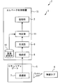
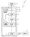
- FIG. 1 is a configuration diagram of a user recognition system according to Embodiment 1.
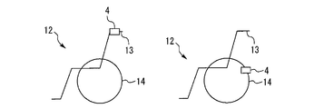
- FIG. 2 is a diagram illustrating an example of a wheelchair provided with the wireless tag according to the first embodiment.
- FIG. 4 is a diagram illustrating an example of detection of a user by a detection unit according to Embodiment 1.
- FIG. 5 is a diagram illustrating an example of generation of trajectory information by a generation unit according to Embodiment 1.
- FIG. 5 is a diagram illustrating an example of a determination by a determination unit according to the first embodiment.
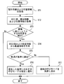
- 5 is a flowchart illustrating an example of an operation of the user recognition system according to the first embodiment.
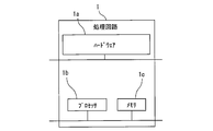
- FIG. 2 is a diagram illustrating a hardware configuration of a main part of the user recognition system according to the first embodiment.
- FIG. 7 is a configuration diagram of a user recognition system according to a modification of the first embodiment.
- FIG. 7 is a configuration diagram of a user recognition system according to a modification of the first embodiment.
- FIG. 1 is a configuration diagram of a user recognition system according to the first embodiment.
- the user recognition system 1 is applied to the elevator system 2.
- the elevator system 2 is applied to buildings.
- the building has a plurality of floors.
- the hoistway passes through each floor of the building.
- landings are provided on each floor of the building.
- the elevator system 2 includes a car. The car is provided to be able to move up and down inside the hoistway.
- the elevator system 2 includes a registration unit 3.
- the registration unit 3 is a part that registers a user's call in the car based on the notified call mode.
- the call mode is a call mode corresponding to the user.
- the call mode includes information such as whether or not the user uses the movement aid and the type of the movement aid. The operation of the car in which the call of the user is registered is controlled based on the call mode.
- the user recognition system 1 includes a wireless tag 4, a security gate 5, and a call control device 6.
- the wireless tag 4 is carried by the user.
- the wireless tag 4 stores identification information.
- the identification information is information for identifying a user.
- the wireless tag 4 includes an element for acquiring current position information.
- the position information is, for example, three-dimensional coordinates (x, y, z).
- the position information is acquired by, for example, a satellite positioning system or an indoor positioning system.
- the identification information and the position information are transmitted from the wireless tag 4 by a wireless signal at predetermined time intervals.
- the wireless tag 4 is provided on a wheelchair on which a user rides.
- Wheelchairs are examples of mobility aids that include wheels.
- the security gate 5 is provided on at least one of a plurality of floors of the building.
- the security gate 5 is provided, for example, on the entrance floor.
- the entrance floor is, for example, a floor where an entrance of a building is provided.
- the security gate 5 is provided on a route leading to the landing.
- the security gate 5 is a device that restricts a user on a route leading to the landing by opening and closing.
- the landing on the floor where the security gate 5 is provided is surrounded by a structure such as a wall to prevent a user who does not pass through the route from entering.
- the security gate 5 includes a receiving unit 7.
- the receiving unit 7 is a unit that receives identification information from the wireless tag 4.
- the receiving unit 7 is, for example, an antenna.
- the security gate 5 is closed when the receiving unit 7 has not received the identification information meeting the predetermined criteria.
- the receiving unit 7 is a unit that acquires the position information of the wireless tag 4.
- the identification information and the position information of the wireless tag 4 are obtained by a wireless signal transmitted from the wireless tag 4.
- the receiving unit 7 stores the acquired identification information and position information.
- the receiving unit 7 includes an element that acquires information on the strength of a wireless signal received from the wireless tag 4.
- the strength of the wireless signal is, for example, an RSSI (Received Signal Strong Strength Indication) value.
- the receiving unit 7 calculates an RSSI value from the position information of the wireless tag 4, for example.
- the receiving unit 7 is connected to the call control device 6 so as to transmit the identification information, the position information, and the information of the RSSI value.
- the call control device 6 includes a detection unit 8, a generation unit 9, a reference storage unit 10, and a determination unit 11.
- the detection unit 8 is a unit that detects a user who intends to enter the landing based on the information of the RSSI value acquired from the reception unit 7.
- the detection unit 8 is connected to the generation unit 9 so that the detection result can be transmitted.
- the generation unit 9 is a unit that generates trajectory information of the trajectory on which the wireless tag 4 moves from the position information of the wireless tag 4.
- the trajectory information is information indicating the trajectory of the moving wireless tag 4.
- the orbit information is, for example, information indicating a change in the height of the wireless tag 4 from the floor with respect to time.
- the trajectory information includes, for example, information on the average value of the height, information on the amplitude of the vibration at the height, or information on the frequency of the vibration at the height.
- the criterion storage unit 10 is a part for storing information of criterion registered in advance.
- the registered criterion indicates a criterion for the trajectory of the moving wireless tag 4.
- an allowable range of the height of the wireless tag 4 from the floor surface is set.
- the allowable range of the amplitude or frequency of the vibration of the height of the wireless tag 4 from the floor is set in the registered standard.
- the registered reference corresponds to the position where the movement assisting device and the wireless tag 4 are provided on the moving assisting device.
- the reference storage unit 10 stores information of the reference to be registered and the call mode in association with each other.
- the determination unit 11 is a unit that determines whether the trajectory of the wireless tag 4 represented by the trajectory information generated by the generation unit 9 matches the criterion registered in the criterion storage unit 10.
- the determination unit 11 is connected to the reference storage unit 10 so as to be able to acquire registered reference information.
- the determination unit 11 is a unit that specifies a call mode based on the determination.
- the designation of the call mode by the determination unit 11 is performed when the identification information received by the reception unit 7 conforms to a predetermined standard.
- the determination unit 11 determines that the trajectory represented by the trajectory information generated by the generation unit 9 matches the registered standard, the call mode stored in the reference storage unit 10 in association with the criterion is determined. It is specified.
- the normal call mode is designated.
- the normal call mode is, for example, a call mode corresponding to a user who does not use the movement assisting device.
- the security gate 5 is closed. At this time, the security gate 5 does not allow a person who enters the building from the entrance to enter the landing. A user in a wheelchair approaches the security gate 5.
- the receiving unit 7 acquires identification information and position information from the wireless tag 4 provided on the wheelchair.
- the call control device 6 acquires the identification information and the position information from the receiving unit 7.
- the receiving unit 7 sequentially stores identification information and position information obtained from wireless signals transmitted at predetermined time intervals.
- the receiving unit 7 accumulates by storing, for example, identification information and position information for n times.
- the detection unit 8 detects a user who intends to enter the landing based on the information of the RSSI value acquired from the reception unit 7.
- the call control device 6 discards the obtained identification information and position information.
- the receiving unit 7 discards the stored identification information and position information.
- the generation unit 9 does not generate the trajectory information.
- the detecting unit 8 detects a user
- the generating unit 9 generates trajectory information from the position information of the wireless tag 4 acquired from the receiving unit 7.
- the security gate 5 determines whether the identification information conforms to a predetermined criterion. If the identification information meets the predetermined criteria, the security gate 5 opens.
- the determination unit 11 determines whether the trajectory of the wireless tag 4 represented by the trajectory information generated by the generation unit 9 matches the criterion registered in the criterion storage unit 10.
- the determination unit 11 specifies a call mode based on the determination.
- the determination unit 11 notifies the designated call mode to the registration unit 3 of the elevator system 2.
- the registration unit 3 registers the user's call in the car based on the notified call mode.
- FIG. 2 is a diagram illustrating an example of a wheelchair provided with the wireless tag according to the first embodiment.
- the wireless tag 4 is provided on, for example, a handle 13 of a wheelchair 12.
- the height of the wireless tag 4 does not change due to the movement of the wheelchair 12. That is, the wireless tag 4 moves on a track whose height from the floor is constant.
- the allowable range of the height of the wireless tag 4 from the floor is set based on the reference stored in the reference storage unit 10 as the reference corresponding to the position where the wheelchair 12 and the wireless tag 4 are provided.
- the wireless tag 4 is provided, for example, on wheels 14 of a wheelchair 12.
- the movement of the wheelchair 12 causes the wireless tag 4 to rotate together with the wheels 14. That is, the wireless tag 4 moves on a track that vibrates in the height direction from the floor surface with an amplitude corresponding to the position provided on the wheel 14 and a frequency corresponding to the rotation speed of the wheel 14.
- the allowable range of the amplitude or frequency of the vibration of the wireless tag 4 from the floor is set.
- FIG. 3 is a diagram illustrating an example of detection of a user by the detection unit according to the first embodiment.
- the horizontal axis represents the RSSI value acquired by the receiving unit 7.
- a threshold value for the RSSI value is set.
- the threshold is -10 dBm.
- the detecting unit 8 determines that the user has an intention to enter the landing. At this time, the detection unit 8 detects a user trying to enter the landing.
- the detection unit 8 allows the user to enter the landing. Judge that there is no intention to do so. At this time, the detection unit 8 does not detect a user trying to enter the landing.
- FIG. 4 is a diagram illustrating an example of generation of trajectory information by the generation unit according to the first embodiment.
- the vertical axis represents the RSSI value acquired by the call control unit from the receiving unit 7.
- the horizontal axis represents the horizontal distance from the receiving unit 7 to the wireless tag 4.
- the RSSI value depends on the distance from the receiving unit 7 to the wireless tag 4 and the like.
- the RSSI value increases as the distance from the receiving unit 7 to the wireless tag 4 decreases. For this reason, even when the wireless tag 4 is moving on a track whose height from the floor is constant, the RSSI value changes depending on the horizontal distance from the receiving unit 7 to the wireless tag 4. Therefore, the generation unit 9 determines the horizontal distance from the reception unit 7 to the wireless tag 4 so that the RSSI value is constant when the wireless tag 4 is moving on a track with a constant height from the floor. Normalize the RSSI value.
- the horizontal distance from the receiving unit 7 to the wireless tag 4 is calculated based on the position information of the wireless tag 4.
- the vertical axis represents the normalized RSSI value.
- the horizontal axis represents the horizontal distance from the receiving unit 7 to the wireless tag 4.
- the generation unit 9 acquires the time information together with the position information of the wireless tag 4.
- the generation unit 9 generates information representing a change in the height of the wireless tag 4 from the floor with respect to time from the information on the height of the wireless tag 4 from the floor and the information on the time as the track information.
- FIG. 5 is a diagram illustrating an example of a determination by the determining unit according to the first embodiment.
- the horizontal axis represents the amplitude of the vibration of the trajectory represented by the trajectory information generated by the generation unit 9.
- the amplitude of the vibration is calculated as a level expression of the minimum value of the amount of vibration with reference to the maximum value of the amount of vibration in the trajectory information.
- the amplitude of the vibration is the difference between the minimum value and the maximum value of the normalized RSSI value.
- the allowable range of the amplitude of the vibration is set based on the reference stored in the reference storage unit 10.
- the tolerance range is between -13 dB and -7 dB.
- the horizontal axis represents the frequency of the orbital vibration represented by the orbital information generated by the generating unit 9.
- the allowable range of the vibration frequency is set based on the reference stored in the reference storage unit 10.
- the allowable range is a range between 30 cycles / min and 50 cycles / min.
- the allowable range of the height of the wireless tag 4 is set based on the reference stored in the reference storage unit 10.
- the height of the wireless tag 4 is represented by, for example, a normalized RSSI value.
- the determination unit 11 determines that the trajectory meets the criterion.
- FIG. 6 is a flowchart illustrating an example of an operation of the user recognition system according to the first embodiment.
- step ST1 the receiving unit 7 acquires the identification information and the position information from the wireless tag 4. Thereafter, the operation of the user recognition system 1 proceeds to step ST2.
- step ST2 the call control device 6 acquires the RSSI value, the identification information, and the position information from the receiving unit 7. Thereafter, the operation of the user recognition system 1 proceeds to step ST3.
- step ST3 the call control device 6 determines whether or not the detection unit 8 detects a user trying to enter the hall. When the result of the determination is Yes, the operation of the user recognition system 1 proceeds to step ST4. When the determination result is No, the call control device 6 discards the identification information and the position information acquired from the receiving unit 7. Thereafter, the operation of the user recognition system 1 ends.
- step ST4 the generation unit 9 generates trajectory information from the RSSI value and the position information acquired from the reception unit 7. Thereafter, the operation of the user recognition system 1 proceeds to step ST5.
- step ST5 the determination unit 11 determines whether the trajectory represented by the trajectory information generated by the generation unit 9 matches the criterion stored in the criterion storage unit 10. If the result of the determination is Yes, the operation of the user recognition system 1 proceeds to step ST6. When the result of the determination is No, the operation of the user recognition system 1 proceeds to step ST7.
- step ST6 the determination unit 11 specifies a call mode corresponding to a criterion to which the trajectory represented by the trajectory information generated by the generation unit 9 conforms. After that, the determination unit 11 notifies the registration unit 3 of the specified call mode. Thereafter, the operation of the user recognition system 1 ends.
- step ST7 the determination unit 11 specifies a normal call mode. After that, the determination unit 11 notifies the registration unit 3 of the specified call mode. Thereafter, the operation of the user recognition system 1 ends.
- the user recognition system 1 includes the wireless tag 4, the receiving unit 7, the generating unit 9, and the determining unit 11.
- the wireless tag 4 is provided on a user's movement assisting device.
- the receiving unit 7 receives identification information for identifying a user from the wireless tag 4.
- the receiving unit 7 acquires the position information of the wireless tag 4.
- the generating unit 9 generates orbit information of the wireless tag 4 from the position information acquired by the receiving unit 7.
- the determination unit 11 determines whether the trajectory represented by the trajectory information generated by the generation unit 9 matches the criteria registered in advance.
- the determination unit 11 specifies a call mode based on the determination to register a call.
- the wireless tag 4 moves on a specific trajectory according to the type and part of the movement assisting tool on which the wireless tag 4 is provided. For this reason, the call is registered in the elevator car by the natural movement of the user who moves using the movement assisting tool to enter the elevator hall. Thereby, the user can register the call by the operation of approaching using the elevator to use the elevator without performing the predetermined operation for registering the call in the predetermined area.
- the operation of the car in which the user's call is registered is controlled based on the call mode.
- the call mode includes information such as whether or not the user uses the movement aid and the type of the movement aid. Further, the call of the user is made based on the trajectory information of the wireless tag 4 that moves with the movement of the user. For this reason, the user can use the car that is driven in accordance with the moving aid used, without performing a call registration operation such as holding a card. As a result, convenience for the user is improved.
- the burden on a user riding on a mobility aid such as the wheelchair 12 and a user pushing the wheelchair 12 is reduced. Also, the user can register the call smoothly. For this reason, traffic congestion of the user that occurs in the elevator system 2 linked to the security gate 5 is reduced.
- the user recognition system 1 specifies a call mode based on a wireless signal from the wireless tag 4. For this reason, the user recognition system 1 does not require a camera.
- the wireless tag 4 is provided on the wheel 14 of the wheelchair 12, which is a movement aid.
- the wireless tag 4 rotates together with the wheels 14.
- the vibration of the track of the wireless tag 4 is stabilized. Thereby, the accuracy of the determination by the determination unit 11 is improved.
- the user recognition system 1 includes the detection unit 8.
- the detection unit 8 detects a user who is going to enter the elevator hall based on the intensity of the signal received by the reception unit 7 from the wireless tag 4.
- the generation unit 9 generates trajectory information when the detection unit 8 detects a user.
- the generator 9 generates trajectory information for the wireless tag 4 of the user determined by the detector 8 to have an intention to enter the landing. As a result, generation of unnecessary trajectory information is omitted.
- the generator 9 generates orbit information from the intensity of the signal received by the receiver 7 from the wireless tag 4 and the position information.
- the generation unit 9 can improve the accuracy of the trajectory information by combining the position information and the information of the change in the strength of the wireless signal. it can.
- the determination unit 11 determines that the trajectory matches the criterion. Is determined. In this case, the determination unit 11 specifies a call mode corresponding to the criterion.
- ⁇ Vibration amplitude can be calculated from the maximum and minimum values of the amount of vibration.
- the determination unit 11 does not require processing such as image recognition. Therefore, the determination unit 11 can reduce the amount of calculation involved in the determination.
- the determination unit 11 determines that the trajectory conforms to the criterion. Then, the judgment is made. In this case, the determination unit 11 specifies a call mode corresponding to the criterion.
- the frequency of vibration can be calculated from a sequence of values of the amount of vibration.
- the determination unit 11 does not require processing such as image recognition. Therefore, the determination unit 11 can reduce the amount of calculation involved in the determination.
- the movement assisting device is a device that assists the user in moving, and may be any device that can get on the elevator car.
- the movement aid may be a walker, a walking car, or an electric wheelchair.
- the wireless tag 4 may acquire the position information by receiving wireless signals transmitted from a plurality of transmitters.
- Each of the plurality of transmitters is provided, for example, on the entrance floor.
- the position information of the wireless tag 4 may be obtained by a position detecting device.
- the position detecting device is provided, for example, on the entrance floor.
- the position detecting device may be, for example, a plurality of receivers that receive a wireless signal transmitted from the wireless tag 4.
- the wireless tag 4 does not need to acquire the position information.
- the receiving unit 7 acquires the position information of the wireless tag 4 from the position detecting device.
- the call control device 6 may store the user identification information in association with the destination floor information.
- the call control device 6 may notify the registration unit 3 of destination floor information together with the designated call mode.
- the registration unit 3 may simultaneously register a call to the destination floor.
- the user recognition system 1 may share the wireless tag 4 provided in another system with the system.
- the elevator system 2 may include a plurality of cars. At this time, the elevator system 2 includes a group management device. The group management device may select a car to which the call is assigned based on the call mode notified to the registration unit 3.
- FIG. 7 is a diagram illustrating a hardware configuration of a main part of the user recognition system according to the first embodiment.
- Each function of the user recognition system 1 can be realized by a processing circuit.
- the processing circuit includes at least one processor 1b and at least one memory 1c.
- the processing circuit may include at least one dedicated hardware 1a together with or as a substitute for the processor 1b and the memory 1c.
- each function of the user recognition system 1 is realized by software, firmware, or a combination of software and firmware. At least one of software and firmware is described as a program.
- the program is stored in the memory 1c.
- the processor 1b realizes each function of the user recognition system 1 by reading and executing a program stored in the memory 1c.
- the processor 1b is also referred to as a CPU (Central Processing Unit), a processing device, an arithmetic device, a microprocessor, a microcomputer, or a DSP.
- the memory 1c includes, for example, a nonvolatile or volatile semiconductor memory such as a RAM, a ROM, a flash memory, an EPROM, and an EEPROM, a magnetic disk, a flexible disk, an optical disk, a compact disk, a mini disk, and a DVD.
- a nonvolatile or volatile semiconductor memory such as a RAM, a ROM, a flash memory, an EPROM, and an EEPROM, a magnetic disk, a flexible disk, an optical disk, a compact disk, a mini disk, and a DVD.
- the processing circuit includes the dedicated hardware 1a
- the processing circuit is realized by, for example, a single circuit, a composite circuit, a programmed processor, a parallel programmed processor, an ASIC, an FPGA, or a combination thereof.
- Each function of the user recognition system 1 can be realized by a processing circuit.
- each function of the user recognition system 1 can be realized by a processing circuit collectively.
- a part of each function of the user recognition system 1 may be realized by dedicated hardware 1a, and the other part may be realized by software or firmware.
- the processing circuit realizes each function of the user recognition system 1 by hardware 1a, software, firmware, or a combination thereof.
- FIG. 8 is a configuration diagram of a user recognition system according to a modification of the first embodiment.
- the user recognition system 1 includes an elevator control device 15.
- the elevator control device 15 includes a registration unit 3, a detection unit 8, a generation unit 9, a reference storage unit 10, and a determination unit 11. Elevator control device 15 operates similarly to call control device 6 and registration unit 3 in the first embodiment.
- FIG. 9 is a configuration diagram of a user recognition system according to a modification of the first embodiment.
- the user recognition system 1 includes a security gate 5.
- the security gate 5 includes an antenna unit 16.
- the antenna unit 16 includes the receiving unit 7 and an antenna control unit 17.
- the antenna control unit 17 includes a detection unit 8, a generation unit 9, a reference storage unit 10, and a determination unit 11.
- Antenna control unit 17 operates similarly to call control device 6 in the first embodiment.
- the user recognition system according to the present invention can be applied to elevators.
- 1 user recognition system 1a hardware, 1b processor, 1c memory, 2 elevator system, 3 registration unit, 4 wireless tag, 5 security gate, 6 call control device, 7 reception unit, 8 detection unit, 9 generation unit, 10
- Reference storage unit ⁇ 11 ⁇ determination unit, ⁇ 12 ⁇ wheelchair, ⁇ 13 ⁇ steering wheel, ⁇ 14 ⁇ wheels, ⁇ 15 ⁇ elevator control device, ⁇ 16 ⁇ antenna unit, ⁇ 17 ⁇ antenna control unit
Landscapes
- Engineering & Computer Science (AREA)
- Automation & Control Theory (AREA)
- Elevator Control (AREA)
- Indicating And Signalling Devices For Elevators (AREA)
Abstract
Description
本発明は、エレベータの利用者認識システムに関する。 The present invention relates to an elevator user recognition system.
特許文献1にエレベータシステムの例が記載されている。エレベータシステムにおいて、乗場に設けられるセンサが予め定められた利用者の動作を検知する場合に、利用者の呼びが登録される。
しかしながら、特許文献1に記載のエレベータシステムにおいて、利用者は、センサが予め定められた動作を検知できる区域まで呼びの登録のために移動する必要がある。このため、利用者が接近してくる方向などによって、移動補助具を用いて移動する利用者にとって当該区域の配置が不便なことがある。
However, in the elevator system described in
本発明は、このような課題を解決するためになされた。本発明の目的は、予め定められた区域で呼びの登録のための予め定められた動作をすることなく、エレベータを利用するために移動補助具を用いて接近する動作によって呼びを登録できるエレベータの利用者認識システムを提供することである。 The present invention has been made to solve such problems. SUMMARY OF THE INVENTION It is an object of the present invention to provide an elevator capable of registering a call by an approaching operation using a mobility aid to use the elevator without performing a predetermined operation for registering a call in a predetermined area. The purpose is to provide a user recognition system.
本発明に係るエレベータの利用者認識システムは、利用者の移動補助具に設けられる無線タグから利用者を識別する識別情報を受信し、無線タグの位置情報を取得する受信部と、受信部が取得した位置情報から無線タグの軌道情報を生成する生成部と、生成部が生成した軌道情報に表される軌道が予め定められた基準に適合するかの判定を行い、呼びを登録するために判定に基づいて呼びモードを指定する判定部と、を備える。 A user recognition system for an elevator according to the present invention includes: a receiving unit that receives identification information for identifying a user from a wireless tag provided on a user's movement assisting tool and acquires position information of the wireless tag; A generation unit that generates trajectory information of the wireless tag from the acquired position information, and determines whether a trajectory represented by the trajectory information generated by the generation unit conforms to a predetermined criterion, and registers a call. A determination unit that specifies a call mode based on the determination.
本発明に係るエレベータの利用者認識システムは、利用者の移動補助具に設けられる無線タグと、無線タグから利用者を識別する識別情報を受信し、無線タグの位置情報を取得する受信部と、受信部が取得した位置情報から無線タグの軌道情報を生成する生成部と、生成部が生成した軌道情報に表される軌道が予め定められた基準に適合するかの判定を行い、呼びを登録するために判定に基づいて呼びモードを指定する判定部と、を備える。 An elevator user recognition system according to the present invention includes a wireless tag provided on a user's movement assisting device, a receiving unit that receives identification information for identifying a user from the wireless tag, and obtains position information of the wireless tag. A generation unit that generates the trajectory information of the wireless tag from the position information obtained by the reception unit, and determines whether the trajectory represented by the trajectory information generated by the generation unit conforms to a predetermined criterion, and calls the call. A determination unit for specifying a call mode based on the determination for registration.
これらの発明によれば、無線タグは、利用者の移動補助具に設けられる。生成部は、無線タグの位置情報から無線タグの軌道情報を生成する。判定部は、無線タグの軌道情報が予め定められた基準に適合するかの判定を行う。判定部は、呼びを登録するために判定に基づいて呼びモードを指定する。これにより、予め定められた区域で呼びの登録のための予め定められた動作をすることなく、エレベータを利用するために移動補助具を用いて接近する動作によって呼びを登録できる。 According to these inventions, the wireless tag is provided on the user's movement assisting device. The generation unit generates track information of the wireless tag from the position information of the wireless tag. The determination unit determines whether orbit information of the wireless tag meets predetermined criteria. The determination unit specifies a call mode based on the determination for registering a call. Thus, the call can be registered by the approaching operation using the movement assisting tool to use the elevator without performing the predetermined operation for registering the call in the predetermined area.
本発明を実施するための形態について添付の図面を参照しながら説明する。各図において、同一または相当する部分には同一の符号を付して、重複する説明は適宜に簡略化または省略する。 A mode for carrying out the present invention will be described with reference to the accompanying drawings. In the drawings, the same or corresponding portions are denoted by the same reference characters, and overlapping description will be appropriately simplified or omitted.
実施の形態1.
図1は、実施の形態1に係る利用者認識システムの構成図である。
FIG. 1 is a configuration diagram of a user recognition system according to the first embodiment.
利用者認識システム1は、エレベータシステム2に適用される。
The
エレベータシステム2は、建築物に適用される。建築物は、複数の階を備える。エレベータシステム2において、昇降路は、建築物の各階を貫く。エレベータシステム2において、乗場は、建築物の各階に設けられる。エレベータシステム2は、かごを備える。かごは、昇降路の内部において昇降しうるように設けられる。
The
エレベータシステム2は、登録部3を備える。登録部3は、通知される呼びモードに基づいて、利用者の呼びをかごに登録する部分である。呼びモードは、利用者に対応する呼びのモードである。呼びモードは、利用者の移動補助具の使用の有無および移動補助具の種類などの情報を含む。利用者の呼びが登録されるかごは、呼びモードに基づいて動作の制御が行われる。
The
利用者認識システム1は、無線タグ4と、セキュリティゲート5と、呼び制御装置6と、を備える。
The
無線タグ4は、利用者に所持される。無線タグ4は、識別情報を記憶する。識別情報は、利用者を識別する情報である。無線タグ4は、現在の位置情報を取得する素子を搭載する。位置情報は、例えば3次元の座標(x,y,z)である。位置情報は、例えば衛星測位システムまたは屋内測位システムなどによって取得される。識別情報および位置情報は、無線タグ4から無線信号によって、予め定められた時間間隔で送信される。
The
無線タグ4は、利用者が搭乗する車椅子に設けられる。車椅子は、車輪を備える移動補助具の例である。
The
セキュリティゲート5は、建築物の複数の階の少なくともいずれかに設けられる。セキュリティゲート5は、例えば玄関階に設けられる。玄関階は、例えば建築物の出入口が設けられる階である。セキュリティゲート5は、乗場に通じる経路に設けられる。セキュリティゲート5は、乗場に通じる経路の利用者による通行を開閉によって制限する装置である。エレベータシステム2において、セキュリティゲート5が設けられる階の乗場は、当該経路を通過しない利用者の進入を防ぐように、例えば壁などの構造物によって囲まれる。セキュリティゲート5は、受信部7を備える。
The
受信部7は、無線タグ4から識別情報を受信する部分である。受信部7は、例えばアンテナである。予め定められた基準に適合する識別情報を受信部7が受信していないときに、セキュリティゲート5は閉じている。
The receiving
受信部7はまた、無線タグ4の位置情報を取得する部分である。識別情報および無線タグ4の位置情報は、無線タグ4から送信される無線信号によって取得される。受信部7は、取得した識別情報および位置情報を記憶する。受信部7は、無線タグ4から受信する無線信号の強度の情報を取得する素子を搭載する。無線信号の強度は、例えばRSSI(Received Signal Strength Indication)値である。受信部7は、例えば無線タグ4の位置情報からRSSI値を算出する。受信部7は、識別情報、位置情報およびRSSI値の情報を送信しうるように、呼び制御装置6に接続される。
(4) The receiving
呼び制御装置6は、検出部8と、生成部9と、基準記憶部10と、判定部11と、を備える。
The
検出部8は、受信部7から取得するRSSI値の情報に基づいて、乗場に進入しようとする利用者を検出する部分である。検出部8は、検出の結果を送信しうるように、生成部9に接続される。
The
生成部9は、無線タグ4の位置情報から無線タグ4が移動する軌道の軌道情報を生成する部分である。軌道情報は、移動する無線タグ4の軌道を表す情報である。軌道情報は、例えば、無線タグ4の床面からの高さの時間に対する変化を表す情報である。軌道情報は、例えば、高さの平均値の情報、高さの振動の振幅の情報または高さの振動の周波数の情報を含む。
The
基準記憶部10は、予め登録される基準の情報を記憶する部分である。登録される基準は、移動する無線タグ4の軌道に対する基準を表す。登録される基準において、例えば無線タグ4の床面からの高さの許容範囲が設定される。あるいは、登録される基準において、例えば無線タグ4の床面からの高さの振動の振幅または周波数の許容範囲が設定される。登録される基準は、移動補助具および無線タグ4が移動補助具に設けられる位置に対応する。基準記憶部10は、登録される基準の情報と、呼びモードと、を対応付けて記憶する。
The
判定部11は、生成部9が生成した軌道情報に表される無線タグ4の軌道が、基準記憶部10に登録されている基準に適合するかの判定を行う部分である。判定部11は、登録されている基準の情報を取得しうるように、基準記憶部10に接続される。
The
判定部11はまた、判定に基づいて呼びモードを指定する部分である。判定部11による呼びモードの指定は、受信部7が受信した識別情報が予め定められた基準に適合する場合に行われる。生成部9が生成した軌道情報に表される軌道が登録される基準に適合するとの判定を判定部11が行うときに、当該基準に対応付けて基準記憶部10に記憶されている呼びモードが指定される。一方、生成部9が生成した軌道情報に表される軌道が登録される基準に適合するとの判定を判定部11が行わないときに、通常の呼びモードが指定される。通常の呼びモードは、例えば移動補助具を使用しない利用者に対応する呼びのモードである。
The
引き続き図1を用いて、利用者認識システム1の動作の概要を説明する。
(4) An outline of the operation of the
通常時において、セキュリティゲート5は、閉じている。このとき、セキュリティゲート5は、出入口から建築物に入る者を乗場に進入させない。車椅子に搭乗する利用者は、セキュリティゲート5に接近する。受信部7は、車椅子に設けられる無線タグ4から識別情報および位置情報を取得する。
に お い て In normal times, the
呼び制御装置6は、識別情報および位置情報を受信部7から取得する。受信部7は、予め定められた時間間隔で送信される無線信号から取得した識別情報および位置情報を順次記憶する。受信部7は、例えばn回分の識別情報および位置情報を記憶することによって蓄積する。検出部8は、受信部7から取得するRSSI値の情報に基づいて、乗場に進入しようとする利用者の検出を行う。
The
検出部8が利用者を検出しない場合に、呼び制御装置6は、取得した識別情報および位置情報を破棄する。受信部7は、蓄積している識別情報および位置情報を破棄する。このとき、生成部9は、軌道情報を生成しない。
When the detecting
一方、検出部8が利用者を検出する場合に、生成部9は、受信部7から取得する無線タグ4の位置情報から軌道情報を生成する。セキュリティゲート5は、予め定められた基準に識別情報が適合するかの判定を行う。識別情報が予め定められた基準に適合する場合に、セキュリティゲート5は開く。判定部11は、生成部9が生成した軌道情報に表される無線タグ4の軌道が、基準記憶部10に登録されている基準に適合するかの判定を行う。判定部11は、当該判定に基づいて、呼びモードを指定する。判定部11は、指定した呼びモードをエレベータシステム2の登録部3に通知する。登録部3は、通知された呼びモードに基づいて、利用者の呼びをかごに登録する。
On the other hand, when the detecting
利用者は、セキュリティゲート5が設けられる経路を通過して乗場に進入する。利用者は、乗場において、呼びが登録されたかごの到着を待機する。その後、利用者は、かごを利用して目的階に移動する。
(4) The user enters the landing through the route where the
続いて、図2を用いて無線タグ4が設けられる車椅子12の例を説明する。
図2は、実施の形態1に係る無線タグが設けられる車椅子の例を示す図である。
Subsequently, an example of the
FIG. 2 is a diagram illustrating an example of a wheelchair provided with the wireless tag according to the first embodiment.
図2の左側に示されるように、無線タグ4は、例えば車椅子12のハンドル13に設けられる。
無線 As shown on the left side of FIG. 2, the
この場合に、車椅子12の移動によって、無線タグ4の高さは変化しない。すなわち、無線タグ4は、床面からの高さが一定の軌道上を移動する。この場合の車椅子12および無線タグ4が設けられる位置に対応する基準として基準記憶部10が記憶する基準において、無線タグ4の床面からの高さの許容範囲が設定される。
In this case, the height of the
図2の右側に示されるように、無線タグ4は、例えば車椅子12の車輪14に設けられる。
無線 As shown on the right side of FIG. 2, the
この場合に、車椅子12の移動によって、無線タグ4は車輪14とともに回転する。すなわち、無線タグ4は、車輪14に設けられる位置に応じた振幅と車輪14の回転速度に応じた周波数とによって床面からの高さ方向に振動する軌道上を移動する。この場合の車椅子12および無線タグ4が設けられる位置に対応する基準として基準記憶部10が記憶する基準において、無線タグ4の床面からの高さの振動の振幅または周波数の許容範囲が設定される。
In this case, the movement of the
続いて、図3を用いて検出部8による利用者の検出を説明する。
図3は、実施の形態1に係る検出部による利用者の検出の例を示す図である。
Subsequently, detection of a user by the
FIG. 3 is a diagram illustrating an example of detection of a user by the detection unit according to the first embodiment.
図3において、横軸は受信部7が取得するRSSI値を表す。検出部8において、RSSI値に対する閾値が設定される。この例において、閾値は-10dBmである。
In FIG. 3, the horizontal axis represents the RSSI value acquired by the receiving
受信部7から取得するRSSI値が閾値を超えている時間が予め定められた時間以上のときに、検出部8は、利用者が乗場に進入しようとする意思があると判定する。このとき、検出部8は、乗場に進入しようとする利用者を検出する。
(4) When the time during which the RSSI value obtained from the receiving
一方、受信部7から取得するRSSI値が閾値を超えている時間が予め定められた時間より短いとき、または、RSSI値が閾値を超えないときに、検出部8は、利用者が乗場に進入しようとする意思がないと判定する。このとき、検出部8は、乗場に進入しようとする利用者を検出しない。
On the other hand, when the time during which the RSSI value obtained from the
続いて、図4を用いて生成部9による軌道情報の生成を説明する。
図4は、実施の形態1に係る生成部による軌道情報の生成の例を示す図である。
Subsequently, generation of the trajectory information by the
FIG. 4 is a diagram illustrating an example of generation of trajectory information by the generation unit according to the first embodiment.
図4の上側のグラフにおいて、縦軸は、呼び制御部が受信部7から取得するRSSI値を表す。横軸は、受信部7から無線タグ4までの水平距離を表す。
に お い て In the upper graph of FIG. 4, the vertical axis represents the RSSI value acquired by the call control unit from the receiving
RSSI値は、受信部7から無線タグ4までの距離などに依存する。RSSI値は、受信部7から無線タグ4までの距離が短いほど、大きい値となる。このため、無線タグ4が床面からの高さが一定の軌道上を移動している場合でも、RSSI値は、受信部7から無線タグ4までの水平距離によって変化する。そこで、生成部9は、無線タグ4が床面からの高さが一定の軌道上を移動している場合にRSSI値が一定になるように、受信部7から無線タグ4までの水平距離によってRSSI値を正規化する。受信部7から無線タグ4までの水平距離は、無線タグ4の位置情報に基づいて算出される。
The RSSI value depends on the distance from the receiving
図4の下側のグラフにおいて、縦軸は、正規化されたRSSI値を表す。横軸は、受信部7から無線タグ4までの水平距離を表す。
に お い て In the lower graph of FIG. 4, the vertical axis represents the normalized RSSI value. The horizontal axis represents the horizontal distance from the receiving
無線タグ4の床面上の水平方向の位置によるRSSI値への影響は、正規化によって補正される。このため、正規化されたRSSI値は、無線タグ4の床面上の水平方向の位置によらない、無線タグ4の床面からの高さの情報を表す。生成部9は、無線タグ4が水平方向に移動している場合に、無線タグ4の位置情報とともに時刻の情報を取得する。生成部9は、軌道情報として、無線タグ4の床面からの高さの情報と時刻の情報とから、無線タグ4の床面からの高さの時間に対する変化を表す情報を生成する。
(4) The influence of the horizontal position of the
続いて、図5を用いて判定部11による判定を説明する。
図5は、実施の形態1に係る判定部による判定の例を示す図である。
Subsequently, the determination by the
FIG. 5 is a diagram illustrating an example of a determination by the determining unit according to the first embodiment.
図5の上側のグラフにおいて、横軸は、生成部9が生成した軌道情報が表す軌道の振動の振幅をあらわす。
に お い て In the upper graph of FIG. 5, the horizontal axis represents the amplitude of the vibration of the trajectory represented by the trajectory information generated by the
ここで、振動の振幅は、軌道情報において振動する量の最大値を基準とした当該振動する量の最小値のレベル表現として算出される。例えば軌道情報が正規化されたRSSI値によって表されているときに、振動の振幅は、正規化されたRSSI値の最小値と最大値との差である。 Here, the amplitude of the vibration is calculated as a level expression of the minimum value of the amount of vibration with reference to the maximum value of the amount of vibration in the trajectory information. For example, when the trajectory information is represented by a normalized RSSI value, the amplitude of the vibration is the difference between the minimum value and the maximum value of the normalized RSSI value.
例えば無線タグ4が車椅子12の車輪14に設けられるときに、基準記憶部10が記憶する基準において、振動の振幅の許容範囲が設定される。この例において、許容範囲は-13dBから-7dBまでの間の範囲である。生成部9が生成した軌道情報が表す軌道の振動の振幅が当該許容範囲に含まれるときに、判定部11は、当該軌道が当該基準に適合するとの判定を行う。
For example, when the
図5の下側のグラフにおいて、横軸は、生成部9が生成した軌道情報が表す軌道の振動の周波数をあらわす。
In the lower graph of FIG. 5, the horizontal axis represents the frequency of the orbital vibration represented by the orbital information generated by the generating
例えば無線タグ4が車椅子12の車輪14に設けられるときに、基準記憶部10が記憶する基準において、振動の周波数の許容範囲が設定される。この例において、許容範囲は30周期/minから50周期/minまでの間の範囲である。生成部9が生成した軌道情報が表す軌道の振動の周波数が当該許容範囲に含まれるときに、判定部11は、当該軌道が当該基準に適合するとの判定を行う。
For example, when the
あるいは、例えば無線タグ4が車椅子12のハンドル13に設けられるときに、基準記憶部10が記憶する基準において、無線タグ4の高さの許容範囲が設定される。無線タグ4の高さは、例えば正規化されたRSSI値によって表される。生成部9が生成した軌道情報が表す無線タグ4の高さが当該許容範囲に含まれるときに、判定部11は、当該軌道が当該基準に適合するとの判定を行う。
Alternatively, for example, when the
続いて、図6を用いて利用者認識システム1の動作を説明する。
図6は、実施の形態1に係る利用者認識システムの動作の例を示すフローチャートである。
Next, the operation of the
FIG. 6 is a flowchart illustrating an example of an operation of the user recognition system according to the first embodiment.
ステップST1において、受信部7は、無線タグ4から識別情報および位置情報を取得する。その後、利用者認識システム1の動作は、ステップST2に進む。
に お い て In step ST1, the receiving
ステップST2において、呼び制御装置6は、RSSI値、識別情報および位置情報を受信部7から取得する。その後、利用者認識システム1の動作は、ステップST3に進む。
In step ST2, the
ステップST3において、呼び制御装置6は、検出部8が乗場に進入しようとする利用者を検出するかを判定する。判定結果がYesの場合に、利用者認識システム1の動作は、ステップST4に進む。判定結果がNoの場合に、呼び制御装置6は、受信部7から取得した識別情報および位置情報を破棄する。その後、利用者認識システム1の動作は、終了する。
In step ST3, the
ステップST4において、生成部9は、受信部7から取得したRSSI値および位置情報から軌道情報を生成する。その後、利用者認識システム1の動作は、ステップST5に進む。
In step ST4, the
ステップST5において、判定部11は、生成部9が生成した軌道情報に表される軌道が基準記憶部10に記憶される基準に適合するかを判定する。判定結果がYesの場合に、利用者認識システム1の動作は、ステップST6に進む。判定結果がNoの場合に、利用者認識システム1の動作は、ステップST7に進む。
In step ST5, the
ステップST6において、判定部11は、生成部9が生成した軌道情報に表される軌道が適合した基準に対応する呼びモードを指定する。その後、判定部11は、指定した呼びモードを登録部3に通知する。その後、利用者認識システム1の動作は、終了する。
In step ST6, the
ステップST7において、判定部11は、通常の呼びモードを指定する。その後、判定部11は、指定した呼びモードを登録部3に通知する。その後、利用者認識システム1の動作は、終了する。
判定 In step ST7, the
以上に説明したように、実施の形態1に係る利用者認識システム1は、無線タグ4と、受信部7と、生成部9と、判定部11と、を備える。無線タグ4は、利用者の移動補助具に設けられる。受信部7は、無線タグ4から利用者を識別する識別情報を受信する。受信部7は、無線タグ4の位置情報を取得する。生成部9は、受信部7が取得した位置情報から無線タグ4の軌道情報を生成する。判定部11は、生成部9が生成した軌道情報に表される軌道が予め登録される基準に適合するかの判定を行う。判定部11は、呼びを登録するために当該判定に基づいて呼びモードを指定する。
As described above, the
無線タグ4は、無線タグ4が設けられる移動補助具の種類および部分に応じて、特有の軌道上を移動する。このため、エレベータの乗場に進入しようとして移動補助具を用いて移動する利用者の自然な動作によって、エレベータのかごに呼びが登録される。これにより、利用者は、予め定められた区域で呼びの登録のための予め定められた動作をすることなく、エレベータを利用するために移動補助具を用いて接近する動作によって呼びを登録できる。
The
利用者の呼びが登録されるかごは、呼びモードに基づいて動作の制御が行われる。呼びモードは、利用者の移動補助具の使用の有無および移動補助具の種類などの情報を含む。また、利用者の呼びは、利用者の移動とともに移動する無線タグ4の軌道情報に基づいて行われる。このため、利用者は、カードをかざすなどの呼びの登録のための動作をすることなく、使用している移動補助具に対応して運転されるかごを利用できる。これにより、利用者の利便性が高くなる。車椅子12などの移動補助具に搭乗している利用者および車椅子12を押している利用者などの負担が緩和される。また、利用者は、呼びの登録がスムーズにできる。このため、セキュリティゲート5に連動するエレベータシステム2などにおいて生じる利用者の渋滞が緩和される。
ご The operation of the car in which the user's call is registered is controlled based on the call mode. The call mode includes information such as whether or not the user uses the movement aid and the type of the movement aid. Further, the call of the user is made based on the trajectory information of the
利用者認識システム1は、無線タグ4からの無線信号に基づいて呼びモードを指定する。このため、利用者認識システム1は、カメラを必要としない。
The
また、無線タグ4は、移動補助具である車椅子12の車輪14に設けられる。
無線 The
無線タグ4は、車輪14とともに回転する。車輪14が安定して回転して移動しているときに、無線タグ4の軌道の振動は安定する。これによって、判定部11による判定の精度が高められる。
The
また、利用者認識システム1は、検出部8を備える。検出部8は、受信部7が無線タグ4から受信する信号の強度に基づいてエレベータの乗場に進入しようとする利用者を検出する。生成部9は、検出部8が利用者を検出する場合に軌道情報を生成する。
(4) The
生成部9は、乗場に進入しようとする意思があると検出部8に判定された利用者の無線タグ4について軌道情報を生成する。これにより、不要な軌道情報の生成が省かれる。
The
また、生成部9は、受信部7が無線タグ4から受信する信号の強度と位置情報とから軌道情報を生成する。
{Circle around (4)} The
例えば屋内測位システムなどにおいて、高い精度の位置情報が得られない場合がある。このとき、位置情報の高さ方向の精度が単独では十分でない場合においても、生成部9は、位置情報と無線信号の強度の変化の情報とを組み合わせることによって、軌道情報の精度を高めることができる。
For example, in an indoor positioning system, etc., high-accuracy position information may not be obtained. At this time, even when the accuracy in the height direction of the position information alone is not sufficient, the
また、判定部11は、生成部9が生成した軌道情報に表される軌道の振動の振幅が予め登録される基準において設定される範囲の内にある場合に、当該軌道が当該基準に適合するとの判定を行う。この場合に、判定部11は、当該基準に対応する呼びモードを指定する。
In addition, when the amplitude of the vibration of the trajectory represented by the trajectory information generated by the
振動の振幅は、振動する量の最大値および最小値によって算出できる。判定部11は、画像認識などの処理を必要としない。このため、判定部11は、判定に伴う計算量を抑えられる。
振幅 Vibration amplitude can be calculated from the maximum and minimum values of the amount of vibration. The
また、判定部11は、生成部9が生成した前記軌道情報に表される軌道の振動の周波数が予め登録される基準において設定される範囲の内にある場合に、当該軌道が当該基準に適合するとの判定を行う。この場合に、判定部11は、当該基準に対応する呼びモードを指定する。
In addition, when the frequency of the vibration of the trajectory represented by the trajectory information generated by the
振動の周波数は、振動する量の値の列によって算出できる。判定部11は、画像認識などの処理を必要としない。このため、判定部11は、判定に伴う計算量を抑えられる。
The frequency of vibration can be calculated from a sequence of values of the amount of vibration. The
なお、移動補助具は、利用者の移動を補助する器具であって、エレベータのかごに乗車できるものであればよい。移動補助具は、歩行器、歩行車または電動車椅子であってもよい。 移動 The movement assisting device is a device that assists the user in moving, and may be any device that can get on the elevator car. The movement aid may be a walker, a walking car, or an electric wheelchair.
無線タグ4は、複数の送信機から送信される無線信号を受信することによって、位置情報を取得してもよい。複数の送信機の各々は、例えば玄関階に設けられる。
The
無線タグ4の位置情報は、位置検出装置によって取得されるものでもよい。位置検出装置は、例えば玄関階に設けられる。位置検出装置は、例えば無線タグ4から送信される無線信号を受信する複数の受信機であってもよい。このとき、無線タグ4は、位置情報を取得しなくてもよい。この場合、受信部7は、位置検出装置から無線タグ4の位置情報を取得する。
位置 The position information of the
呼び制御装置6は、利用者の識別情報に行先階の情報を関連付けて記憶してもよい。呼び制御装置6は、指定された呼びモードとともに行先階の情報を登録部3に通知してもよい。登録部3は、行先階への呼びを同時に登録してもよい。
The
利用者認識システム1は、他のシステムが備える無線タグ4を当該システムと共用してもよい。
The
エレベータシステム2は、複数のかごを備えてもよい。このとき、エレベータシステム2は、群管理装置を備える。群管理装置は、登録部3に通知される呼びモードに基づいて、呼びを割当てるかごの選択を行ってもよい。
The
続いて、図7を用いて利用者認識システム1のハードウェア構成の例について説明する。
図7は、実施の形態1に係る利用者認識システムの主要部のハードウェア構成を示す図である。
Next, an example of a hardware configuration of the
FIG. 7 is a diagram illustrating a hardware configuration of a main part of the user recognition system according to the first embodiment.
利用者認識システム1の各機能は、処理回路により実現し得る。処理回路は、少なくとも1つのプロセッサ1bと少なくとも1つのメモリ1cとを備える。処理回路は、プロセッサ1bおよびメモリ1cと共に、あるいはそれらの代用として、少なくとも1つの専用のハードウェア1aを備えてもよい。
Each function of the
処理回路がプロセッサ1bとメモリ1cとを備える場合、利用者認識システム1の各機能は、ソフトウェア、ファームウェア、またはソフトウェアとファームウェアとの組み合わせで実現される。ソフトウェアおよびファームウェアの少なくとも一方は、プログラムとして記述される。そのプログラムはメモリ1cに格納される。プロセッサ1bは、メモリ1cに記憶されたプログラムを読み出して実行することにより、利用者認識システム1の各機能を実現する。
When the processing circuit includes the
プロセッサ1bは、CPU(Central Processing Unit)、処理装置、演算装置、マイクロプロセッサ、マイクロコンピュータ、DSPともいう。メモリ1cは、例えば、RAM、ROM、フラッシュメモリ、EPROM、EEPROM等の、不揮発性または揮発性の半導体メモリ、磁気ディスク、フレキシブルディスク、光ディスク、コンパクトディスク、ミニディスク、DVD等により構成される。
The
処理回路が専用のハードウェア1aを備える場合、処理回路は、例えば、単一回路、複合回路、プログラム化したプロセッサ、並列プログラム化したプロセッサ、ASIC、FPGA、またはこれらの組み合わせで実現される。
When the processing circuit includes the
利用者認識システム1の各機能は、それぞれ処理回路で実現することができる。あるいは、利用者認識システム1の各機能は、まとめて処理回路で実現することもできる。利用者認識システム1の各機能について、一部を専用のハードウェア1aで実現し、他部をソフトウェアまたはファームウェアで実現してもよい。このように、処理回路は、ハードウェア1a、ソフトウェア、ファームウェア、またはこれらの組み合わせで利用者認識システム1の各機能を実現する。
Each function of the
続いて、図8を用いて実施の形態1の変形例を説明する。
図8は、実施の形態1の変形例に係る利用者認識システムの構成図である。
Next, a modification of the first embodiment will be described with reference to FIG.
FIG. 8 is a configuration diagram of a user recognition system according to a modification of the first embodiment.
利用者認識システム1は、エレベータ制御装置15を備える。エレベータ制御装置15は、登録部3と、検出部8と、生成部9と、基準記憶部10と、判定部11と、を備える。エレベータ制御装置15は、実施の形態1における呼び制御装置6および登録部3と同様に動作する。
The
続いて、図9を用いて実施の形態1の他の変形例を説明する。
図9は、実施の形態1の変形例に係る利用者認識システムの構成図である。
Next, another modified example of the first embodiment will be described with reference to FIG.
FIG. 9 is a configuration diagram of a user recognition system according to a modification of the first embodiment.
利用者認識システム1は、セキュリティゲート5を備える。セキュリティゲート5は、アンテナ部16を備える。アンテナ部16は、受信部7と、アンテナ制御部17と、を備える。アンテナ制御部17は、検出部8と、生成部9と、基準記憶部10と、判定部11と、を備える。アンテナ制御部17は、実施の形態1における呼び制御装置6と同様に動作する。
The
本発明に係る利用者認識システムは、エレベータに適用できる。 利用 The user recognition system according to the present invention can be applied to elevators.
1 利用者認識システム、 1a ハードウェア、 1b プロセッサ、 1c メモリ、 2 エレベータシステム、 3 登録部、 4 無線タグ、 5 セキュリティゲート、 6 呼び制御装置、 7 受信部、 8 検出部、 9 生成部、 10 基準記憶部、 11 判定部、 12 車椅子、 13 ハンドル、 14 車輪、 15 エレベータ制御装置、 16 アンテナ部、 17 アンテナ制御部 1 user recognition system, 1a hardware, 1b processor, 1c memory, 2 elevator system, 3 registration unit, 4 wireless tag, 5 security gate, 6 call control device, 7 reception unit, 8 detection unit, 9 generation unit, 10 Reference storage unit, {11} determination unit, {12} wheelchair, {13} steering wheel, {14} wheels, {15} elevator control device, {16} antenna unit, {17} antenna control unit
Claims (7)
前記受信部が取得した前記位置情報から前記無線タグの軌道情報を生成する生成部と、
前記生成部が生成した前記軌道情報に表される軌道が予め登録される基準に適合するかの判定を行い、呼びを登録するために前記判定に基づいて呼びモードを指定する判定部と、
を備えるエレベータの利用者認識システム。 A receiving unit that receives identification information for identifying the user from a wireless tag provided in a user's movement assistance tool, and acquires position information of the wireless tag,
A generating unit that generates trajectory information of the wireless tag from the position information acquired by the receiving unit,
A determination unit that determines whether the trajectory represented by the trajectory information generated by the generation unit conforms to a pre-registered criterion, and specifies a call mode based on the determination to register a call,
Elevator user recognition system comprising:
前記無線タグから前記利用者を識別する識別情報を受信し、前記無線タグの位置情報を取得する受信部と、
前記受信部が取得した前記位置情報から前記無線タグの軌道情報を生成する生成部と、
前記生成部が生成した前記軌道情報に表される軌道が予め登録される基準に適合するかの判定を行い、呼びを登録するために前記判定に基づいて呼びモードを指定する判定部と、
を備えるエレベータの利用者認識システム。 A wireless tag provided on a user's mobility aid,
A receiving unit that receives identification information for identifying the user from the wireless tag, and obtains position information of the wireless tag,
A generating unit that generates trajectory information of the wireless tag from the position information obtained by the receiving unit,
A determination unit that determines whether the trajectory represented by the trajectory information generated by the generation unit conforms to a pre-registered criterion, and specifies a call mode based on the determination to register a call,
Elevator user recognition system comprising:
を備え、
前記生成部は、前記検出部が前記利用者を検出する場合に前記軌道情報を生成する請求項1から請求項3のいずれか一項に記載のエレベータの利用者認識システム。 A detection unit that detects the user who is about to enter an elevator landing based on the strength of a signal that the reception unit receives from the wireless tag;
With
4. The elevator user recognition system according to claim 1, wherein the generation unit generates the trajectory information when the detection unit detects the user. 5.
Priority Applications (3)
| Application Number | Priority Date | Filing Date | Title |
|---|---|---|---|
| CN201880094382.5A CN112313165B (en) | 2018-07-03 | 2018-07-03 | Elevator user identification system |
| JP2020506283A JP6733847B2 (en) | 2018-07-03 | 2018-07-03 | Elevator user recognition system |
| PCT/JP2018/025266 WO2020008540A1 (en) | 2018-07-03 | 2018-07-03 | User recognition system of elevator |
Applications Claiming Priority (1)
| Application Number | Priority Date | Filing Date | Title |
|---|---|---|---|
| PCT/JP2018/025266 WO2020008540A1 (en) | 2018-07-03 | 2018-07-03 | User recognition system of elevator |
Publications (1)
| Publication Number | Publication Date |
|---|---|
| WO2020008540A1 true WO2020008540A1 (en) | 2020-01-09 |
Family
ID=69060481
Family Applications (1)
| Application Number | Title | Priority Date | Filing Date |
|---|---|---|---|
| PCT/JP2018/025266 Ceased WO2020008540A1 (en) | 2018-07-03 | 2018-07-03 | User recognition system of elevator |
Country Status (3)
| Country | Link |
|---|---|
| JP (1) | JP6733847B2 (en) |
| CN (1) | CN112313165B (en) |
| WO (1) | WO2020008540A1 (en) |
Cited By (1)
| Publication number | Priority date | Publication date | Assignee | Title |
|---|---|---|---|---|
| JP7275367B1 (en) | 2022-08-29 | 2023-05-17 | 三菱電機ビルソリューションズ株式会社 | elevator control system |
Families Citing this family (2)
| Publication number | Priority date | Publication date | Assignee | Title |
|---|---|---|---|---|
| CN113753696A (en) * | 2021-09-07 | 2021-12-07 | 北方工业大学 | An intelligent wheelchair and elevator communication control system |
| JP7722603B2 (en) * | 2022-12-14 | 2025-08-13 | 三菱電機ビルソリューションズ株式会社 | Elevator user attribute acquisition system and elevator user attribute acquisition method |
Citations (6)
| Publication number | Priority date | Publication date | Assignee | Title |
|---|---|---|---|---|
| JPH0318564A (en) * | 1989-06-16 | 1991-01-28 | Hitachi Elevator Eng & Service Co Ltd | Controller for elevator |
| JP2003048671A (en) * | 2001-08-07 | 2003-02-21 | Dainippon Printing Co Ltd | Elevator management system and elevator call tag |
| JP2009298507A (en) * | 2008-06-11 | 2009-12-24 | Mitsubishi Electric Building Techno Service Co Ltd | Automatic registration system of elevator for wheelchair user |
| JP2015003785A (en) * | 2013-06-20 | 2015-01-08 | 三菱電機株式会社 | Elevator operation device and elevator control device |
| JP2015016917A (en) * | 2013-07-08 | 2015-01-29 | 株式会社日立製作所 | Elevator system |
| JP2017024858A (en) * | 2015-07-22 | 2017-02-02 | 株式会社日立ビルシステム | Elevator car call system and portable information terminal |
Family Cites Families (9)
| Publication number | Priority date | Publication date | Assignee | Title |
|---|---|---|---|---|
| JPH0346973A (en) * | 1989-07-12 | 1991-02-28 | Hitachi Ltd | Elevator control device |
| JP4811651B2 (en) * | 2006-03-30 | 2011-11-09 | 独立行政法人産業技術総合研究所 | Wheelchair user detection system using stereo camera |
| WO2013030898A1 (en) * | 2011-09-02 | 2013-03-07 | 三菱電機株式会社 | Wheelchair operating apparatus for elevator |
| CN104364182B (en) * | 2012-07-24 | 2016-03-09 | 三菱电机株式会社 | Elevator device |
| JP6235326B2 (en) * | 2013-12-12 | 2017-11-22 | 株式会社日立製作所 | Elevator system |
| JP6269302B2 (en) * | 2014-05-02 | 2018-01-31 | 富士通株式会社 | Wheelchair use determination system, wheelchair use determination program, and wheelchair use determination method |
| CN104866795B (en) * | 2015-05-14 | 2018-04-10 | 清华大学 | Location positioning method, system and two-dimentional code encoding method based on Quick Response Code |
| JP6058742B2 (en) * | 2015-06-04 | 2017-01-11 | 東芝エレベータ株式会社 | Elevator system |
| JP3220895U (en) * | 2019-01-28 | 2019-04-11 | 株式会社テクノスジャパン | Wheelchair tag and deaf person detection device using the wheelchair tag |
-
2018
- 2018-07-03 JP JP2020506283A patent/JP6733847B2/en active Active
- 2018-07-03 CN CN201880094382.5A patent/CN112313165B/en active Active
- 2018-07-03 WO PCT/JP2018/025266 patent/WO2020008540A1/en not_active Ceased
Patent Citations (6)
| Publication number | Priority date | Publication date | Assignee | Title |
|---|---|---|---|---|
| JPH0318564A (en) * | 1989-06-16 | 1991-01-28 | Hitachi Elevator Eng & Service Co Ltd | Controller for elevator |
| JP2003048671A (en) * | 2001-08-07 | 2003-02-21 | Dainippon Printing Co Ltd | Elevator management system and elevator call tag |
| JP2009298507A (en) * | 2008-06-11 | 2009-12-24 | Mitsubishi Electric Building Techno Service Co Ltd | Automatic registration system of elevator for wheelchair user |
| JP2015003785A (en) * | 2013-06-20 | 2015-01-08 | 三菱電機株式会社 | Elevator operation device and elevator control device |
| JP2015016917A (en) * | 2013-07-08 | 2015-01-29 | 株式会社日立製作所 | Elevator system |
| JP2017024858A (en) * | 2015-07-22 | 2017-02-02 | 株式会社日立ビルシステム | Elevator car call system and portable information terminal |
Cited By (2)
| Publication number | Priority date | Publication date | Assignee | Title |
|---|---|---|---|---|
| JP7275367B1 (en) | 2022-08-29 | 2023-05-17 | 三菱電機ビルソリューションズ株式会社 | elevator control system |
| JP2024032338A (en) * | 2022-08-29 | 2024-03-12 | 三菱電機ビルソリューションズ株式会社 | elevator control system |
Also Published As
| Publication number | Publication date |
|---|---|
| CN112313165B (en) | 2022-08-12 |
| JP6733847B2 (en) | 2020-08-05 |
| CN112313165A (en) | 2021-02-02 |
| JPWO2020008540A1 (en) | 2020-07-09 |
Similar Documents
| Publication | Publication Date | Title |
|---|---|---|
| US7702420B2 (en) | Method for making mobile unit accompany objective person | |
| JP6780625B2 (en) | Self-driving vehicle allocation system and self-driving vehicles | |
| US20190345000A1 (en) | Robotic destination dispatch system for elevators and methods for making and using same | |
| US12012301B2 (en) | Elevator system | |
| WO2020008540A1 (en) | User recognition system of elevator | |
| CN109928291B (en) | User guidance system and user guidance method | |
| CN103670121A (en) | Method and device for automatically actuating a closing element of a motor vehicle | |
| CN110621602B (en) | elevator system | |
| US20230315117A1 (en) | Mobile body control device, mobile body control method, and non-transitory computer-readable storage medium | |
| JPWO2019138447A1 (en) | Elevator system | |
| KR20160110809A (en) | Parking system for guiding an optimal path and method thereof | |
| TW201724000A (en) | Automated guided elevator assistant system and guide method | |
| Ilkovičová et al. | Pedestrian indoor positioning and tracking using smartphone sensors, step detection and map matching algorithm | |
| CN116893667A (en) | Moving bodies and control methods | |
| Török et al. | Drear-towards infrastructure-free indoor localization via dead-reckoning enhanced with activity recognition | |
| CN110844722A (en) | Elevator car assignment based on proximity inference of potential passengers | |
| CN115028031B (en) | Mobile body management systems and elevators | |
| US12214992B2 (en) | Control apparatus for elevator | |
| KR20160086921A (en) | Positioning system and program | |
| KR20170098436A (en) | A support system for mobility conveniences for the elderly | |
| JP6947336B2 (en) | Mobile control system, mobile, and mobile system | |
| JP2007101492A (en) | Mobile robot distance and position detection device | |
| KR102898587B1 (en) | Ultra-wideband-based, elevator-to-floor movement method and system for mobile robots for autonomous driving of multi-story buildings | |
| JP7398317B2 (en) | Vehicle driving support method and driving support device | |
| JP6403175B1 (en) | Passenger detection device provided in a vehicle capable of unmanned traveling, and a vehicle allocation system using the device |
Legal Events
| Date | Code | Title | Description |
|---|---|---|---|
| ENP | Entry into the national phase |
Ref document number: 2020506283 Country of ref document: JP Kind code of ref document: A |
|
| 121 | Ep: the epo has been informed by wipo that ep was designated in this application |
Ref document number: 18925171 Country of ref document: EP Kind code of ref document: A1 |
|
| NENP | Non-entry into the national phase |
Ref country code: DE |
|
| 122 | Ep: pct application non-entry in european phase |
Ref document number: 18925171 Country of ref document: EP Kind code of ref document: A1 |