WO2020008572A1 - Dispositif de commande pour véhicules ferroviaires - Google Patents
Dispositif de commande pour véhicules ferroviaires Download PDFInfo
- Publication number
- WO2020008572A1 WO2020008572A1 PCT/JP2018/025397 JP2018025397W WO2020008572A1 WO 2020008572 A1 WO2020008572 A1 WO 2020008572A1 JP 2018025397 W JP2018025397 W JP 2018025397W WO 2020008572 A1 WO2020008572 A1 WO 2020008572A1
- Authority
- WO
- WIPO (PCT)
- Prior art keywords
- command
- control unit
- voltage
- power conversion
- circuit
- Prior art date
- Legal status (The legal status is an assumption and is not a legal conclusion. Google has not performed a legal analysis and makes no representation as to the accuracy of the status listed.)
- Ceased
Links
Images


Classifications
-
- B—PERFORMING OPERATIONS; TRANSPORTING
- B60—VEHICLES IN GENERAL
- B60L—PROPULSION OF ELECTRICALLY-PROPELLED VEHICLES; SUPPLYING ELECTRIC POWER FOR AUXILIARY EQUIPMENT OF ELECTRICALLY-PROPELLED VEHICLES; ELECTRODYNAMIC BRAKE SYSTEMS FOR VEHICLES IN GENERAL; MAGNETIC SUSPENSION OR LEVITATION FOR VEHICLES; MONITORING OPERATING VARIABLES OF ELECTRICALLY-PROPELLED VEHICLES; ELECTRIC SAFETY DEVICES FOR ELECTRICALLY-PROPELLED VEHICLES
- B60L3/00—Electric devices on electrically-propelled vehicles for safety purposes; Monitoring operating variables, e.g. speed, deceleration or energy consumption
- B60L3/04—Cutting off the power supply under fault conditions
-
- B—PERFORMING OPERATIONS; TRANSPORTING
- B60—VEHICLES IN GENERAL
- B60L—PROPULSION OF ELECTRICALLY-PROPELLED VEHICLES; SUPPLYING ELECTRIC POWER FOR AUXILIARY EQUIPMENT OF ELECTRICALLY-PROPELLED VEHICLES; ELECTRODYNAMIC BRAKE SYSTEMS FOR VEHICLES IN GENERAL; MAGNETIC SUSPENSION OR LEVITATION FOR VEHICLES; MONITORING OPERATING VARIABLES OF ELECTRICALLY-PROPELLED VEHICLES; ELECTRIC SAFETY DEVICES FOR ELECTRICALLY-PROPELLED VEHICLES
- B60L15/00—Methods, circuits, or devices for controlling the traction-motor speed of electrically-propelled vehicles
- B60L15/20—Methods, circuits, or devices for controlling the traction-motor speed of electrically-propelled vehicles for control of the vehicle or its driving motor to achieve a desired performance, e.g. speed, torque, programmed variation of speed
- B60L15/2009—Methods, circuits, or devices for controlling the traction-motor speed of electrically-propelled vehicles for control of the vehicle or its driving motor to achieve a desired performance, e.g. speed, torque, programmed variation of speed for braking
-
- B—PERFORMING OPERATIONS; TRANSPORTING
- B60—VEHICLES IN GENERAL
- B60L—PROPULSION OF ELECTRICALLY-PROPELLED VEHICLES; SUPPLYING ELECTRIC POWER FOR AUXILIARY EQUIPMENT OF ELECTRICALLY-PROPELLED VEHICLES; ELECTRODYNAMIC BRAKE SYSTEMS FOR VEHICLES IN GENERAL; MAGNETIC SUSPENSION OR LEVITATION FOR VEHICLES; MONITORING OPERATING VARIABLES OF ELECTRICALLY-PROPELLED VEHICLES; ELECTRIC SAFETY DEVICES FOR ELECTRICALLY-PROPELLED VEHICLES
- B60L3/00—Electric devices on electrically-propelled vehicles for safety purposes; Monitoring operating variables, e.g. speed, deceleration or energy consumption
- B60L3/0023—Detecting, eliminating, remedying or compensating for drive train abnormalities, e.g. failures within the drive train
- B60L3/003—Detecting, eliminating, remedying or compensating for drive train abnormalities, e.g. failures within the drive train relating to inverters
-
- B—PERFORMING OPERATIONS; TRANSPORTING
- B60—VEHICLES IN GENERAL
- B60L—PROPULSION OF ELECTRICALLY-PROPELLED VEHICLES; SUPPLYING ELECTRIC POWER FOR AUXILIARY EQUIPMENT OF ELECTRICALLY-PROPELLED VEHICLES; ELECTRODYNAMIC BRAKE SYSTEMS FOR VEHICLES IN GENERAL; MAGNETIC SUSPENSION OR LEVITATION FOR VEHICLES; MONITORING OPERATING VARIABLES OF ELECTRICALLY-PROPELLED VEHICLES; ELECTRIC SAFETY DEVICES FOR ELECTRICALLY-PROPELLED VEHICLES
- B60L7/00—Electrodynamic brake systems for vehicles in general
- B60L7/10—Dynamic electric regenerative braking
- B60L7/16—Dynamic electric regenerative braking for vehicles comprising converters between the power source and the motor
-
- B—PERFORMING OPERATIONS; TRANSPORTING
- B60—VEHICLES IN GENERAL
- B60L—PROPULSION OF ELECTRICALLY-PROPELLED VEHICLES; SUPPLYING ELECTRIC POWER FOR AUXILIARY EQUIPMENT OF ELECTRICALLY-PROPELLED VEHICLES; ELECTRODYNAMIC BRAKE SYSTEMS FOR VEHICLES IN GENERAL; MAGNETIC SUSPENSION OR LEVITATION FOR VEHICLES; MONITORING OPERATING VARIABLES OF ELECTRICALLY-PROPELLED VEHICLES; ELECTRIC SAFETY DEVICES FOR ELECTRICALLY-PROPELLED VEHICLES
- B60L9/00—Electric propulsion with power supply external to the vehicle
- B60L9/16—Electric propulsion with power supply external to the vehicle using AC induction motors
- B60L9/18—Electric propulsion with power supply external to the vehicle using AC induction motors fed from DC supply lines
- B60L9/20—Electric propulsion with power supply external to the vehicle using AC induction motors fed from DC supply lines single-phase motors
-
- B—PERFORMING OPERATIONS; TRANSPORTING
- B60—VEHICLES IN GENERAL
- B60L—PROPULSION OF ELECTRICALLY-PROPELLED VEHICLES; SUPPLYING ELECTRIC POWER FOR AUXILIARY EQUIPMENT OF ELECTRICALLY-PROPELLED VEHICLES; ELECTRODYNAMIC BRAKE SYSTEMS FOR VEHICLES IN GENERAL; MAGNETIC SUSPENSION OR LEVITATION FOR VEHICLES; MONITORING OPERATING VARIABLES OF ELECTRICALLY-PROPELLED VEHICLES; ELECTRIC SAFETY DEVICES FOR ELECTRICALLY-PROPELLED VEHICLES
- B60L2200/00—Type of vehicles
- B60L2200/26—Rail vehicles
-
- B—PERFORMING OPERATIONS; TRANSPORTING
- B60—VEHICLES IN GENERAL
- B60L—PROPULSION OF ELECTRICALLY-PROPELLED VEHICLES; SUPPLYING ELECTRIC POWER FOR AUXILIARY EQUIPMENT OF ELECTRICALLY-PROPELLED VEHICLES; ELECTRODYNAMIC BRAKE SYSTEMS FOR VEHICLES IN GENERAL; MAGNETIC SUSPENSION OR LEVITATION FOR VEHICLES; MONITORING OPERATING VARIABLES OF ELECTRICALLY-PROPELLED VEHICLES; ELECTRIC SAFETY DEVICES FOR ELECTRICALLY-PROPELLED VEHICLES
- B60L2240/00—Control parameters of input or output; Target parameters
- B60L2240/40—Drive Train control parameters
- B60L2240/52—Drive Train control parameters related to converters
- B60L2240/527—Voltage
-
- Y—GENERAL TAGGING OF NEW TECHNOLOGICAL DEVELOPMENTS; GENERAL TAGGING OF CROSS-SECTIONAL TECHNOLOGIES SPANNING OVER SEVERAL SECTIONS OF THE IPC; TECHNICAL SUBJECTS COVERED BY FORMER USPC CROSS-REFERENCE ART COLLECTIONS [XRACs] AND DIGESTS
- Y02—TECHNOLOGIES OR APPLICATIONS FOR MITIGATION OR ADAPTATION AGAINST CLIMATE CHANGE
- Y02T—CLIMATE CHANGE MITIGATION TECHNOLOGIES RELATED TO TRANSPORTATION
- Y02T10/00—Road transport of goods or passengers
- Y02T10/60—Other road transportation technologies with climate change mitigation effect
- Y02T10/64—Electric machine technologies in electromobility
-
- Y—GENERAL TAGGING OF NEW TECHNOLOGICAL DEVELOPMENTS; GENERAL TAGGING OF CROSS-SECTIONAL TECHNOLOGIES SPANNING OVER SEVERAL SECTIONS OF THE IPC; TECHNICAL SUBJECTS COVERED BY FORMER USPC CROSS-REFERENCE ART COLLECTIONS [XRACs] AND DIGESTS
- Y02—TECHNOLOGIES OR APPLICATIONS FOR MITIGATION OR ADAPTATION AGAINST CLIMATE CHANGE
- Y02T—CLIMATE CHANGE MITIGATION TECHNOLOGIES RELATED TO TRANSPORTATION
- Y02T10/00—Road transport of goods or passengers
- Y02T10/60—Other road transportation technologies with climate change mitigation effect
- Y02T10/72—Electric energy management in electromobility
Definitions
- the present invention relates to a railway vehicle control device.
- the power conversion system disclosed in Patent Literature 1 includes an inverter device as a power conversion unit, and includes an inverter control unit as a control unit that controls the power conversion unit.
- the power converter converts the power supplied from the current collector connected to the primary terminal and supplies the power to the motor connected to the secondary terminal.
- the power converter converts AC power supplied from the electric motor into DC power.
- the voltage on the power collection unit side of the power conversion unit is changed to a power conversion unit mounted on another electric railway vehicle. It is adjusted to a range suitable for supplying power to the system.
- the power conversion unit is stopped when an emergency brake is applied while the electric railway vehicle is running, or when the power conversion unit needs to be protected by detecting an overvoltage or an overcurrent of the power conversion unit. Further, after stopping the power conversion unit, it is conceivable to open a contactor provided between the power collection device and the power conversion unit and electrically disconnect the power conversion unit from the power collection device. In the power conversion system disclosed in Patent Literature 1, when the power conversion unit is stopped and the contactor is opened, even after the power conversion unit is stopped, the power conversion unit stops moving toward the power conversion unit due to mechanical operation delay. Current may continue to flow. As a result, an overvoltage may occur on the primary side of the power conversion unit.
- the present invention has been made in view of the above circumstances, and has as its object to provide a railway vehicle control device capable of suppressing overvoltage on the primary side of a power conversion unit.
- a railway vehicle control device of the present invention includes a torque control unit and a circuit control unit.
- the torque control unit controls the operation of a switching element included in a power conversion unit that performs bidirectional power conversion between a primary side to which a power supply is connected and a secondary side to which a motor is connected, thereby reducing the torque of the motor. Adjust.
- the circuit control unit acquires the voltage on the primary side of the power conversion unit, and operates the step-down circuit connected in parallel to the primary side when the voltage on the primary side is equal to or higher than the reference voltage.
- the torque control unit stops the operation of the switching element of the power conversion unit.
- the circuit control unit operates the step-down circuit.
- the railway vehicle control device upon acquiring the stop command, operates the step-down circuit. Therefore, it is possible to suppress the overvoltage on the primary side of the power conversion unit.
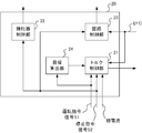
- 1 is a block diagram showing a configuration of a power conversion system for a railway vehicle according to an embodiment of the present invention.
- 1 is a block diagram illustrating a configuration of a railway vehicle control device according to an embodiment.
- 9 is a flowchart illustrating an example of an operation of an overvoltage suppression process performed by the railway vehicle control device according to the embodiment.
- a power conversion system for a railway vehicle (hereinafter referred to as a power conversion system) 1 according to the embodiment of the present invention shown in FIG. 1 is mounted on an electric railway vehicle.
- An operation command is input to the power conversion system 1 from a cab of the electric railway vehicle.
- the operation command includes a powering command for instructing acceleration of the electric railway vehicle or a brake command for instructing deceleration of the electric railway vehicle.
- the power conversion system 1 acquires DC power from an unillustrated substation which is an example of a DC power supply via the overhead wire 2 which is an example of a power supply line.
- the power conversion system 1 drives the motor 8 by converting the DC power into AC power and supplying the AC power to the motor 8.
- the electric motor 8 is driven, the propulsion of the electric railway vehicle is obtained.
- the operation command includes a brake command, that is, at the time of braking, the power conversion system 1 converts the power generated by the electric motor 8 operating as a generator into DC power, and mounts the DC power on another electric railway vehicle via the overhead line 2. To the power conversion system 1.
- the power conversion system 1 is an example of a power collection device, and includes a pantograph 3 that obtains DC power from a substation via an overhead line 2, and power conversion that converts DC power into AC power and supplies the AC power to a motor 8.
- a unit 12 is provided.
- the power conversion system 1 also controls the power conversion unit 12 and controls the contactors 4 and 5 that switch the electrical connection between the pantograph 3 and the power conversion unit 12. ) 20.
- the control device 20 operates the chopper circuit 14 in addition to the control described above.
- the chopper circuit 14 is provided as an example of a step-down circuit, and is connected to the pantograph 3 of the power conversion unit 12 in parallel with the pantograph 3.
- the chopper circuit 14 includes a switching element 15 and a brake resistor 16 connected in series.
- the control device 20 increases the conduction ratio of the switching element 15 included in the chopper circuit 14. As a result, the power output from the power converter 12 is consumed by the chopper circuit 14, and the voltage of the filter capacitor 11 connected to the primary side of the power converter 12 is reduced.
- the power conversion system 1 further includes a voltage detection unit 13 that detects a voltage EFC of the filter capacitor 11 and a current detection unit 9 that detects each of U-phase, V-phase, and W-phase currents flowing through the motor 8.
- the pantograph 3 rises in accordance with the operation on the cab and comes into contact with the overhead wire 2. Thereafter, the control device 20 turns on the contactor 5 with the contactor 4 opened. A resistor 6 is connected to the contactor 5 in series, and power is supplied from the pantograph 3 to the power converter 12 via the contactor 5 and the resistor 6, so that an inrush current may flow through the power converter 12. Is suppressed. Thereafter, when the voltage EFC of the filter capacitor 11 reaches the reference input voltage, the control device 20 turns on the contactor 4 and opens the contactor 5.
- the control device 20 performs the control described below based on the operation command signal S1 and the stop command signal S2.
- the operation command signal S1 is a signal according to the operation of the master controller in the cab, and indicates a powering notch or a brake notch.
- the stop command signal S2 is assumed to be input from an abnormality detection device that detects an abnormality of the electric railway vehicle.
- the stop command signal S2 becomes H (High) level when instructing to turn off the switching element of the power conversion unit 12, and becomes L (Low) level when instructing to maintain the switching operation of the power conversion unit 12.
- the abnormality detection device detects various abnormalities such as an overvoltage and an overcurrent of the power conversion unit 12, an overcurrent of the electric motor 8, and a state where the pantograph 3 is separated from the overhead line 2.
- the control device 20 supplies the power conversion unit 12 from the pantograph 3 via the contactor 4 and the smoothing reactor 7.
- the switching elements of the power conversion unit 12 are turned on and off so as to convert DC power into AC power.
- the power converter 12 supplies the AC power to the electric motor 8 connected to the secondary side.
- the control device 20 calculates a target torque for obtaining the target acceleration indicated by the powering notch, and calculates an actual torque of the electric motor 8 from a current flowing through the electric motor 8. Then, control device 20 controls the operation of the switching element of power conversion unit 12 in order to bring the actual torque closer to the target torque.
- a three-phase induction motor is used as the motor 8, and the control device 20 acquires a current value flowing through the motor 8 from a current detection unit 9 that detects a U-phase, V-phase, and W-phase current flowing through the motor 8.
- the control device 20 causes the power conversion unit 12 to convert regenerative power generated by the motor 8 operating as a generator into DC power.
- the operation of the switching element of the power conversion unit 12 is controlled.
- the DC power is supplied to the power conversion system 1 mounted on another electric railway vehicle via the overhead line 2.
- the voltage EFC of the filter capacitor 11 needs to be higher than the overhead line voltage.
- the voltage EFC is too large than the overhead wire voltage, an overvoltage occurs in the overhead wire voltage.
- control device 20 operates chopper circuit 14 when voltage EFC is equal to or higher than the reference voltage.
- the chopper circuit 14 has a switching element 15 and a brake resistor 16 connected in series.
- the control device 20 has a positive correlation with the voltage EFC, and adjusts the duty ratio of the switching element 15 based on the duty ratio that changes with the time of the voltage EFC.
- the control device 20 operates the chopper circuit 14 without depending on the magnitude relationship between the voltage EFC and the reference voltage. In other words, when the operation command signal S1 indicates a power running notch and the stop command signal S2 goes to the H level, the control device 20 controls the switching element 15 of the chopper circuit 14 even if the voltage EFC is lower than the reference voltage. Increase the flow rate to greater than zero.
- the control device 20 includes a torque control unit 21 that switches on and off a switching element included in the power conversion unit 12, a contactor control unit 22 that turns on or off the contactors 4 and 5, and a chopper circuit 14. It includes a circuit control unit 23 that operates and a target calculation unit 24 that calculates a target torque of the electric motor 8. The outline of each part of the control device 20 will be described.
- the target calculation unit 24 calculates a target torque of the electric motor 8 required to obtain a target acceleration indicated by the power running notch or a target deceleration indicated by the brake command, and sends the target torque to the torque control unit 21.
- the torque controller 21 calculates the actual torque or the regenerative torque of the electric motor 8 from the phase current detected by the current detector 9.
- the torque control unit 21 controls the operation of the switching element of the power conversion unit 12 so that the actual torque or the regenerative torque approaches the target torque. Further, when the operation command signal S1 indicates a power running notch and the stop command signal S2 becomes H level, the torque control unit 21 turns off the switching element of the power conversion unit 12.
- the circuit controller 23 obtains the voltage EFC of the filter capacitor 11 from the voltage detector 13 and, when the voltage EFC is equal to or higher than the reference voltage, switches the chopper circuit 14 based on the conduction ratio having a positive correlation with the voltage EFC.
- the chopper circuit 14 is operated by adjusting the flow rate of the element 15.
- the circuit control unit 23 sets a duty ratio having a positive correlation with the voltage EFC regardless of the magnitude relationship between the voltage EFC and the reference voltage.
- the chopper circuit 14 is operated by switching on and off the switching element 15 of the chopper circuit 14. Note that the circuit control unit 23 can set a limit on the time during which the chopper circuit 14 operates.
- the torque control unit 21 switches on / off of a switching element included in the power conversion unit 12 according to the operation command signal S1 and the stop command signal S2. Specifically, when the operation command signal S1 indicates a power running notch and the stop command signal S2 is at the L level, the torque control unit 21 controls the switching element of the power conversion unit 12 to bring the actual torque close to the target torque. Control behavior. When the operation command signal S1 includes the brake command and the stop command signal S2 is at the L level, the torque control unit 21 controls the operation of the switching element included in the power conversion unit 12 to bring the regenerative torque closer to the target torque. I do. Further, when the stop command signal S2 becomes H level, the torque control unit 21 turns off the switching element of the power conversion unit 12.
- the contactor control unit 22 turns on the contactor 5 with the contactor 4 opened. Thereafter, the contactor control unit 22 turns on the contactor 4 and then opens the contactor 5. That is, during operation of the electric railway vehicle, the contactor 4 is turned on and the contactor 5 is opened.
- the stop command signal S2 becomes H level during operation of the electric railway vehicle, the contactor control unit 22 opens the contactor 4. Thereafter, the closing operation of the contactors 4 and 5 is the same as when the electric railway vehicle starts operating.
- the circuit control unit 23 has a positive correlation with the voltage EFC of the filter capacitor 11 detected by the voltage detection unit 13 when the operation command signal S1 indicates a brake notch and the stop command signal S2 is at the L level.
- the duty ratio of the switching element 15 included in the chopper circuit 14 is adjusted based on the duty ratio of the EFC that changes with time. Specifically, when the voltage EFC of the filter capacitor 11 becomes equal to or higher than the reference voltage E1, the conduction ratio of the switching element 15 included in the chopper circuit 14 is adjusted based on the conduction ratio described above.
- An example of the conduction ratio having a positive correlation with the voltage EFC is shown by a thick solid line in FIG. The conduction ratio indicated by the thick solid line in FIG.
- the conduction ratio when the voltage EFC is equal to or lower than the reference voltage E1 is defined as a minimum conduction ratio R MIN .
- the conduction ratio when the voltage EFC is equal to or higher than the voltage E2 is defined as a maximum conduction ratio R MAX .
- the timing at which the circuit control unit 23 operates the chopper circuit 14 is not limited to the case where the above-described operation command signal S1 indicates a brake notch.
- the circuit control unit 23 determines that the voltage EFC is positive regardless of the magnitude relationship between the voltage EFC of the filter capacitor 11 and the reference voltage E1.
- the duty ratio of the switching element 15 of the chopper circuit 14 is adjusted based on the duty ratio of the voltage EFC that changes with time.
- the circuit control unit 23 has a positive correlation with the voltage EFC.
- the conduction ratio of the switching element 15 is adjusted based on the conduction ratio.
- An example of a conduction ratio having a positive correlation with the voltage EFC when the operation command signal S1 indicates a power running notch and the stop command signal S2 is at the H level is shown by a thin solid line in FIG.
- the conduction ratio indicated by a thin solid line in FIG. 3 increases from the minimum conduction ratio R MIN to the maximum conduction ratio R ′ MAX as the voltage EFC increases.
- the operation command signal S1 indicates a power running notch
- the stop command signal S2 is at the H level
- the conduction ratio when the voltage EFC matches the reference voltage E1 is R1.
- the duty ratio is the minimum duty ratio R MIN as described above.
- the operation command signal S1 indicates a power running notch and the flow rate when the stop command signal S2 is at the H level is determined so that R1> minimum flow rate R MIN .
- the conduction ratio is determined, so that when the stop command signal S2 is acquired, the voltage EFC is quickly reduced. It is possible to do.
- the stop command signal S2 indicates an H level
- the maximum duty ratio R'MAX indicates an operation command signal S1 indicates a brake notch.
- the value is set to a value sufficiently smaller than the maximum conduction ratio R MAX when the command signal S2 is at the L level.
- the pantograph 3 remains in a state from when the switching element of the power conversion unit 12 is turned off until the contactor 4 is opened. Electric power obtained from the substation via the overhead line 2 is supplied to the chopper circuit 14 and may be consumed by the brake resistor 16. Therefore, by setting the maximum conduction ratio R ′ MAX to a value sufficiently smaller than the maximum conduction ratio R MAX , the chopper circuit 14 is prevented from consuming the power acquired by the pantograph 3.
- control device 20 starts the overvoltage suppression process shown in FIG.
- the operation command signal S1 indicates a brake notch, that is, when the operation command signal S1 does not indicate a powering notch
- the circuit control unit 23 compares the voltage EFC of the filter capacitor 11 with the reference voltage E1. (Step S12).
- the processing of steps S11 and S12 is repeated.
- the circuit control unit 23 When the operation command signal S1 indicates a brake notch (Step S11; N) and the voltage EFC is equal to or higher than the reference voltage E1 (Step S12; Y), the circuit control unit 23 has a positive correlation with the voltage EFC, and The duty ratio of the switching element 15 of the chopper circuit 14 is adjusted based on the duty ratio of the EFC that changes with time with time (step S13). Upon completion of the process in the step S13, the process returns to the step S12, and the voltage EFC is compared with the reference voltage E1.
- Step S11; Y When the operation command signal S1 indicates a power running notch (step S11; Y) and the stop command signal S2 is at the L level (step S14; N), the processing of steps S11 and S14 is repeated.
- the operation command signal S1 indicates a power running notch (Step S11; Y) and the stop command signal S2 is at the H level (Step S14; Y), the processes of Steps S15, S16, and S17 described later are performed in parallel.
- the torque control unit 21 turns off the switching element of the power conversion unit 12 (Step S15). Further, the contactor control unit 22 opens the contactor 4 (Step S16).
- the circuit control unit 23 adjusts the duty ratio of the switching element 15 of the chopper circuit 14 (Step S17). Specifically, in step S17, the circuit control unit 23 switches the switching element 15 included in the chopper circuit 14 on and off at a conduction ratio having a positive correlation with the voltage EFC. If the operation time at the minimum flow rate is less than the predetermined time (step S18; N), the processing of step S17 is repeated. Specifically, the circuit control unit 23 has a time measurement circuit, measures the time during which the flow rate is set to the minimum flow rate, and determines whether the measurement time is equal to or longer than a certain time.
- Step S19 the circuit control unit 23 stops the chopper circuit 14 (Step S19). Specifically, in step S19, the circuit control unit 23 turns off the switching element 15 of the chopper circuit 14.
- the control device 20 ends the overvoltage suppression processing. Thereafter, as described above, when the contactor 5 is opened after the contactor 5 and the contactor 4 are turned on in this order and an operation command is input, the control device 20 starts the process of step S11 again.
- the filter capacitor 11 when the stop command is acquired, the filter capacitor 11 is operated by operating the chopper circuit 14 without depending on the magnitude relationship between the voltage EFC and the reference voltage. Overvoltage can be suppressed.
- FIG. 5 is a diagram illustrating a configuration example of hardware of the control device for a railway vehicle according to the embodiment.
- the railway vehicle control device 20 includes a processor 31, a memory 32, and an interface 33 as hardware configurations for controlling the respective units. Each function of these devices is realized by the processor 31 executing a program stored in the memory 32.
- the interface 33 connects each device and establishes communication, and may include a plurality of types of interfaces as necessary.
- FIG. 5 illustrates an example in which the railway vehicle control device 20 includes one processor 31 and one memory 32, a plurality of processors 31 and a plurality of memories 32 may execute each function in cooperation with each other.
- the main part that has the processor 31, the memory 32, and the interface 33 and performs the control processing can be realized by using a normal computer system without using a dedicated system.
- a computer program for executing the above-described operation is stored in a computer-readable recording medium (such as a flexible disk, CD-ROM, or DVD-ROM) and distributed, and the computer program is installed in the computer.
- the railway vehicle control device 20 that executes the above-described processing may be configured.
- the computer program may be stored in a storage device of a server device on a communication network, and downloaded by an ordinary computer system to configure the railway vehicle control device 20.
- the functions of the railway vehicle control device 20 are realized by sharing an OS (operating system) with an application program or by cooperation between the OS and the application program, only the application program portion is recorded on a recording medium or a storage device. May be stored.
- OS operating system
- the computer program may be posted on a bulletin board (BBS: Bulletin Board System) on a communication network, and the computer program may be distributed via the communication network. Then, the above-described processing may be executed by activating the computer program and executing it in the same manner as other application programs under the control of the OS.
- BSS Bulletin Board System
- the circuit configuration of the power conversion system 1 is arbitrary, and is not limited to the above example.
- the contactors 4 and 5 may be connected in series, and the resistor 6 may be connected to the contactor 5 in parallel.
- the contactor 5 is turned on after the contactor 4 is turned on. That is, the contactors 4 and 5 are turned on during the operation of the electric railway vehicle.
- the stop command signal S2 becomes H level, both the contactors 4 and 5 are opened.
- the power collection system of the power conversion system 1 is not limited to the overhead line system described above, and any system that acquires power from a substation can be adopted.
- a surface power collection system, a third rail system, and the like can be given.
- the current collector is any device that acquires power from the overhead wire 2, and is, for example, a trolley pole, a bugel, or the like.
- the operation command may include a coasting command in addition to the powering command and the brake command.
- the circuit control unit 23 operates the chopper circuit 14.
- the configuration of the control device 20 is not limited to the above-described example, and may be any configuration that suppresses the overvoltage of the filter capacitor 11.
- the function of the contactor control unit 22 may be provided as a contactor control device separately from the control device 20. In this case, the contactor control device opens the contactor 4 when the stop command signal S2 becomes H level.
- the conduction ratio is calculated according to any function, table, or the like having a positive correlation with voltage EFC.
- the conduction ratio is calculated based on a linear function, a quadratic function, or the like that uses the voltage of the filter capacitor 11 as a variable.
- the step-down circuit provided on the pantograph 3 side of the power conversion unit 12 is not limited to the chopper circuit 14, and any step-down circuit can be provided.
- a switching regulator may be provided.
- the condition for stopping the chopper circuit 14 is not limited to the example of step S18 in FIG.
- a voltage detector for detecting the voltage on the pantograph 3 side from the contactor 4 is further provided, and the chopper circuit 14 is stopped based on the voltage on the pantograph 3 side of the contactor 4 detected by the voltage detector. Is also good.
- the operation of the chopper circuit 14 may be stopped when the voltage of the contactor 4 on the side of the pantograph 3 is within a desired range for a predetermined time or more.
Landscapes
- Engineering & Computer Science (AREA)
- Power Engineering (AREA)
- Transportation (AREA)
- Mechanical Engineering (AREA)
- Life Sciences & Earth Sciences (AREA)
- Sustainable Development (AREA)
- Sustainable Energy (AREA)
- Electric Propulsion And Braking For Vehicles (AREA)
Abstract
L'invention concerne un dispositif de commande (20) qui comprend une unité de commande de couple (21) et une unité de commande de circuit (23). L'unité de commande de couple (21) commute un élément de commutation dans une unité de conversion de puissance entre les fonctions marche et arrêt conformément à des instructions de fonctionnement. Si les instructions de fonctionnement comprennent une instruction de freinage et que la tension d'un condensateur de filtre est au moins une tension de référence, l'unité de commande de circuit (23) présente une corrélation positive avec la tension du condensateur de filtre et actionne un circuit abaisseur selon un rapport de conduction qui change au fil du temps en conjonction avec les changements dans le temps de la tension de condensateur de filtre. En outre, si l'instruction de fonctionnement comprend une instruction d'alimentation, l'unité de commande de circuit (23) actionne le circuit abaisseur lorsqu'une instruction d'arrêt a été obtenue, indépendamment de la relation entre les tailles de la tension de condensateur de filtre et de la tension de référence.
Priority Applications (3)
| Application Number | Priority Date | Filing Date | Title |
|---|---|---|---|
| PCT/JP2018/025397 WO2020008572A1 (fr) | 2018-07-04 | 2018-07-04 | Dispositif de commande pour véhicules ferroviaires |
| JP2020528609A JP6937913B2 (ja) | 2018-07-04 | 2018-07-04 | 鉄道車両用制御装置 |
| DE112018007793.4T DE112018007793T5 (de) | 2018-07-04 | 2018-07-04 | Steuervorrichtung für eisenbahnfahrzeuge |
Applications Claiming Priority (1)
| Application Number | Priority Date | Filing Date | Title |
|---|---|---|---|
| PCT/JP2018/025397 WO2020008572A1 (fr) | 2018-07-04 | 2018-07-04 | Dispositif de commande pour véhicules ferroviaires |
Publications (1)
| Publication Number | Publication Date |
|---|---|
| WO2020008572A1 true WO2020008572A1 (fr) | 2020-01-09 |
Family
ID=69060226
Family Applications (1)
| Application Number | Title | Priority Date | Filing Date |
|---|---|---|---|
| PCT/JP2018/025397 Ceased WO2020008572A1 (fr) | 2018-07-04 | 2018-07-04 | Dispositif de commande pour véhicules ferroviaires |
Country Status (3)
| Country | Link |
|---|---|
| JP (1) | JP6937913B2 (fr) |
| DE (1) | DE112018007793T5 (fr) |
| WO (1) | WO2020008572A1 (fr) |
Families Citing this family (1)
| Publication number | Priority date | Publication date | Assignee | Title |
|---|---|---|---|---|
| EP4446157A1 (fr) * | 2023-04-13 | 2024-10-16 | Stadler Rail AG | Véhicule ferroviaire comprenant un ensemble sélecteur de système et procédé de changement d'un véhicule ferroviaire dc pour fonctionnement ca ou d'un fonctionnement ca en mode cc |
Citations (3)
| Publication number | Priority date | Publication date | Assignee | Title |
|---|---|---|---|---|
| JPH08126101A (ja) * | 1994-10-20 | 1996-05-17 | Fuji Electric Co Ltd | 車両用電力変換装置の過電圧保護装置 |
| WO2011074045A1 (fr) * | 2009-12-18 | 2011-06-23 | 三菱電機株式会社 | Appareil de commande d'entraînement de véhicule électrique |
| JP2017184448A (ja) * | 2016-03-30 | 2017-10-05 | 三菱電機株式会社 | 電動機制御装置および電動機制御方法 |
-
2018
- 2018-07-04 JP JP2020528609A patent/JP6937913B2/ja active Active
- 2018-07-04 DE DE112018007793.4T patent/DE112018007793T5/de active Pending
- 2018-07-04 WO PCT/JP2018/025397 patent/WO2020008572A1/fr not_active Ceased
Patent Citations (3)
| Publication number | Priority date | Publication date | Assignee | Title |
|---|---|---|---|---|
| JPH08126101A (ja) * | 1994-10-20 | 1996-05-17 | Fuji Electric Co Ltd | 車両用電力変換装置の過電圧保護装置 |
| WO2011074045A1 (fr) * | 2009-12-18 | 2011-06-23 | 三菱電機株式会社 | Appareil de commande d'entraînement de véhicule électrique |
| JP2017184448A (ja) * | 2016-03-30 | 2017-10-05 | 三菱電機株式会社 | 電動機制御装置および電動機制御方法 |
Also Published As
| Publication number | Publication date |
|---|---|
| DE112018007793T5 (de) | 2021-04-01 |
| JPWO2020008572A1 (ja) | 2021-04-08 |
| JP6937913B2 (ja) | 2021-09-22 |
Similar Documents
| Publication | Publication Date | Title |
|---|---|---|
| CN104024029B (zh) | 电动车控制装置以及电动车 | |
| JP6972343B2 (ja) | 鉄道車両用制御装置および離線判定方法 | |
| JP5766640B2 (ja) | 電気車制御装置 | |
| JP5274723B1 (ja) | 電気車制御装置 | |
| US9731607B1 (en) | Vehicle brake control system | |
| CN102470763B (zh) | 电气列车的电力变换装置 | |
| JP2017225279A (ja) | 電力変換システム | |
| JP5968518B2 (ja) | 電気車用主変換装置 | |
| CN109982888B (zh) | 铁路车辆用电路系统 | |
| CN110435485B (zh) | 一种应用于逆变回馈装置的运行控制方法、装置及介质 | |
| JP3345249B2 (ja) | 電気車制御装置 | |
| JP6786268B2 (ja) | 蓄電システム | |
| CN111347941B (zh) | 轨道车辆辅助供电系统及其控制方法 | |
| JP6851502B2 (ja) | 鉄道車両用電力変換システム | |
| JP6937913B2 (ja) | 鉄道車両用制御装置 | |
| JPH02219401A (ja) | 電気車の制御装置 | |
| JP4153879B2 (ja) | 車両駆動制御装置 | |
| CN209813731U (zh) | 轨道车辆辅助供电系统及轨道车辆 | |
| JP7229425B2 (ja) | 電力変換装置 | |
| JP7301686B2 (ja) | 電力変換システム | |
| JPH04322107A (ja) | 交流電気車の制御装置 | |
| JP2007209200A (ja) | 電気車制御装置 | |
| JP2001354053A (ja) | 給電システム | |
| JP2004236397A (ja) | 車両用電力変換器の制御装置 | |
| JPS62221941A (ja) | 回生変電所の制御方法 |
Legal Events
| Date | Code | Title | Description |
|---|---|---|---|
| 121 | Ep: the epo has been informed by wipo that ep was designated in this application |
Ref document number: 18925246 Country of ref document: EP Kind code of ref document: A1 |
|
| ENP | Entry into the national phase |
Ref document number: 2020528609 Country of ref document: JP Kind code of ref document: A |
|
| 122 | Ep: pct application non-entry in european phase |
Ref document number: 18925246 Country of ref document: EP Kind code of ref document: A1 |