WO2020008604A1 - Structure de montage d'engrenage à crémaillère et engrenage à crémaillère - Google Patents
Structure de montage d'engrenage à crémaillère et engrenage à crémaillère Download PDFInfo
- Publication number
- WO2020008604A1 WO2020008604A1 PCT/JP2018/025574 JP2018025574W WO2020008604A1 WO 2020008604 A1 WO2020008604 A1 WO 2020008604A1 JP 2018025574 W JP2018025574 W JP 2018025574W WO 2020008604 A1 WO2020008604 A1 WO 2020008604A1
- Authority
- WO
- WIPO (PCT)
- Prior art keywords
- rack
- rack gear
- body member
- groove
- length direction
- Prior art date
- Legal status (The legal status is an assumption and is not a legal conclusion. Google has not performed a legal analysis and makes no representation as to the accuracy of the status listed.)
- Ceased
Links
Images

Classifications
-
- F—MECHANICAL ENGINEERING; LIGHTING; HEATING; WEAPONS; BLASTING
- F16—ENGINEERING ELEMENTS AND UNITS; GENERAL MEASURES FOR PRODUCING AND MAINTAINING EFFECTIVE FUNCTIONING OF MACHINES OR INSTALLATIONS; THERMAL INSULATION IN GENERAL
- F16H—GEARING
- F16H19/00—Gearings comprising essentially only toothed gears or friction members and not capable of conveying indefinitely-continuing rotary motion
- F16H19/02—Gearings comprising essentially only toothed gears or friction members and not capable of conveying indefinitely-continuing rotary motion for interconverting rotary or oscillating motion and reciprocating motion
- F16H19/04—Gearings comprising essentially only toothed gears or friction members and not capable of conveying indefinitely-continuing rotary motion for interconverting rotary or oscillating motion and reciprocating motion comprising a rack
-
- F—MECHANICAL ENGINEERING; LIGHTING; HEATING; WEAPONS; BLASTING
- F16—ENGINEERING ELEMENTS AND UNITS; GENERAL MEASURES FOR PRODUCING AND MAINTAINING EFFECTIVE FUNCTIONING OF MACHINES OR INSTALLATIONS; THERMAL INSULATION IN GENERAL
- F16H—GEARING
- F16H55/00—Elements with teeth or friction surfaces for conveying motion; Worms, pulleys or sheaves for gearing mechanisms
- F16H55/02—Toothed members; Worms
- F16H55/26—Racks
Definitions
- the present invention relates to a rack and pinion mechanism, and more particularly, to a rack gear mounting structure.
- the rack gear which is a component of the rack and pinion mechanism, undergoes deformation such as warpage or bending during the manufacturing process. For example, in a heat treatment process such as quenching and tempering, the rack gear is likely to be deformed. When the deformation occurs, the processing accuracy in the subsequent manufacturing process of the rack gear decreases.
- a rack gear is mounted on a predetermined rack gear mounting surface in a state where deformation is corrected by applying an external force, and in this state, a gear cutting process, a polishing process, an inspection process, and the like are performed. Further, the rack gear is deformed by applying a large force to the rack gear to plastically deform the rack gear, and the rack gear is mounted on an actual machine.
- Patent Document 1 proposes a method of plastically deforming a rack shaft on which a rack tooth row used for a steering device is formed to remove distortion.
- the cross-sectional area of the center portion is made smaller than that of both ends of the rack shaft, and a force for plastic deformation is applied to the portion of the rack tooth row at the center portion of the rack shaft to remove the warpage of the rack shaft.
- rack gears generally have high rigidity, deformation may not be reliably corrected even when an external force is applied.
- the rack gear is subjected to a gear cutting process, a polishing process, or the like with a deformation or distortion partially remaining.
- the rack gear may be mounted on the actual machine with the deformation or distortion remaining, and an adverse effect may occur such that the engagement with the pinion gear cannot be maintained in an appropriate state.
- An object of the present invention is to provide a rack gear mounting structure that can mount a rack gear on a predetermined rack gear mounting surface in a state in which deformation is reliably corrected during a manufacturing process or use of the rack gear (when mounted on an actual machine). .
- the present invention is a rack gear mounting structure for mounting a rack gear on a predetermined rack gear mounting surface in a state where deformation is corrected by applying an external force,
- the rack gear A rack body member extending linearly, Rack teeth formed on the outer peripheral side surface of the rack body member in the length direction thereof, A plurality of grooves that divide a portion of the rack body member that is different from the portion where the rack teeth are formed along the length direction of the rack body member at predetermined intervals; It is characterized by having.
- the rack gear is fastened and fixed to the reference rack gear mounting surface using fasteners such as bolts.
- a rack gear having a plurality of grooves and reduced rigidity is relatively easily deformed when an external force is applied by a fastener. Therefore, the rack gear can be fastened and fixed to the rack gear mounting surface in a state where the deformation is reliably corrected.
- gear cutting, polishing, and the like By performing gear cutting, polishing, and the like in this state, a rack gear can be manufactured with high accuracy.
- the rack gear returns to its deformed state when it is removed from the rack gear mounting surface after processing and the external force is released.
- the deformation is corrected as in the previous step. Therefore, processing accuracy is maintained.
- the rack gear can be accurately assembled, and the meshing state with the pinion gear can be maintained in an appropriate state. Further, the pinion gear can be accurately mounted on an actual machine without requiring a step of applying a large external force to plastically deform and remove the deformation.
- FIG. 2 is an explanatory diagram showing the rack gear of FIG. 1 and an explanatory diagram showing an example of a deformed state of the rack gear.
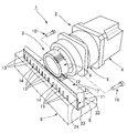
- FIG. 1 is an explanatory view showing an example of a feed mechanism provided with a rack and pinion mechanism.
- the feed mechanism 1 includes a rotary actuator 2 and a rack and pinion mechanism 3.
- the rotary actuator 2 includes a motor 4 and a speed reducer 5 that reduces the rotation of the motor 4 and outputs the rotation.
- the rack and pinion mechanism 3 includes a pinion gear 6 coaxially mounted on the output shaft of the rotary actuator 2, a rack gear 7 meshing with the pinion gear 6, and a mechanism frame 9 on which a rack gear mounting surface 8 is formed.
- the rack gear 7 is fastened and fixed to the rack gear mounting surface 8 by, for example, a fastening bolt 10.
- the feed mechanism 1 has a rack gear mounting structure, whereby the rack gear 7 is fastened and fixed to the rack mounting surface 8 of the mechanism frame 9 in a state where the deformation is corrected by the fastening force of the fastening bolt 10. It is formed.
- FIG. 2A is an explanatory view showing the rack gear 7.
- the rack gear 7 includes a rack body member 11 having a rectangular section and extending straight.
- the cross-sectional shape of the rack body member 11 is not limited to a rectangular cross section, but may be a polygonal or circular cross section.
- a rack tooth row 12 is formed in the length direction 11a.
- the part of the rack main body member 11 is divided at predetermined intervals in the length direction 11 a of the rack main body member 11. Are formed.
- first to fourth side surfaces 21 to 24 4Four flat outer peripheral side surfaces of the rack body member 11 having a rectangular cross section are referred to as first to fourth side surfaces 21 to 24.
- the rack tooth row 12 is formed on the first side surface 21.
- tooth ridges extending in a direction orthogonal to the length direction 11a or in a direction having a predetermined angle are arranged at a constant pitch in the length direction 11a.
- the plurality of grooves 13 are arranged at equal intervals along the length direction 11 a on the third side surface 23 opposite to the first side surface 21.
- Each groove 13 extends in parallel with a width direction 11b orthogonal to the length direction 11a or at a predetermined angle.
- Each groove 13 is provided with a groove opening 13a having a constant width exposed on the third side surface 23 of the rack body member 11, and is formed over the entire width in the width direction 11b on the third side surface 23. It is open on the second side surface 22 and the fourth side surface 24.
- the groove 13 has a rectangular cross section extending perpendicularly to the third side surface 23 from the third side surface 23 toward the first side surface on which the rack teeth 12 are formed.
- the groove 13 of this example is a groove having a groove depth that is approximately half the distance between the third side surface 23 and the first side surface 21, and the groove bottom surface portion is defined by a curved arc surface.
- the rack gear 7 is manufactured, for example, through the following steps. First, the rack body member 11 having a rectangular cross section without the rack teeth 12 and the grooves 13 is manufactured. The rack body member 11 is grooved to form a groove 13. In addition, holes are drilled to form fastening bolt mounting holes 14 and the like. Next, a tooth cutting process is performed to attach the rack teeth 12 to the rack body member 11 having the groove 13. A polishing step and a heat treatment step (hardening, annealing, etc.) are performed on the rack teeth 12 of the rack body member 11 having the rack teeth 12.
- the rack main body member 11 with the rack teeth 12 is deformed before the polishing step or the heat treatment step.
- the rack main body member 11 with the rack teeth 12 is deformed before the polishing step or the heat treatment step.
- the rack main body member 11 is deformed so that the side of the first side surface 21 on which the rack tooth row 12 is formed is slightly curved in the length direction 11a.
- a groove 13 is formed in the rack gear 7 of this example.
- the rack body member 11 in a deformed state is mounted on a rack gear mounting surface (not shown) for polishing by a fastening mechanism.
- the rack body member 11 is mounted on the rack gear mounting surface in a state where the deformation is corrected by applying an external force by the fastening mechanism.
- the portion of the rack body member 11 on the side of the third side surface 23 is divided at regular intervals by the grooves 13 along the length direction 11a, and has low rigidity.
- the rack gear 7 is attached to the actual machine while the deformation remains.
- the rack gear 7 is fastened and fixed to the rack gear mounting surface 8 of the mechanism frame 9 by fastening bolts 10 or the like. Since the rack gear 7 has the groove 13, the deformation of the rack gear 7 is reliably corrected by an external force applied to the rack gear 7 by fastening the fastening bolt 10 or the like. Therefore, the rack gear 7 is accurately assembled to the rack gear mounting surface 8 in a state where the deformation is corrected, and a state in which the rack gear 7 meshes with the pinion gear 6 with high accuracy can be formed.
- the rack gear 7 is formed with an elongated rectangular cross-sectional groove 13 having a constant width and a constant depth.
- the groove 13 may be a groove having a cross-sectional shape other than a rectangle.
- the groove bottom surface portion may not be a curved arc surface.
- the groove may have a triangular cross section that tapers from the groove opening toward the groove bottom.
- the intervals between the grooves 13 may not be equal.
- the gap between the grooves is increased near the mounting hole 14, and the gap between the grooves is reduced near the mounting hole 14. Thereby, the fastening force by the fastening bolt is ensured, and the deformation of the rack gear 7 is reliably corrected.
- a plurality of grooves 13 are formed in the rack body member 11 of the rack gear 7.
- the groove 13 divides a portion of the rack body member 11 that is different from the portion where the rack tooth row 12 is formed at predetermined intervals along the length direction 11a.
Landscapes
- Engineering & Computer Science (AREA)
- General Engineering & Computer Science (AREA)
- Mechanical Engineering (AREA)
- Transmission Devices (AREA)
- Gears, Cams (AREA)
Abstract
Priority Applications (5)
| Application Number | Priority Date | Filing Date | Title |
|---|---|---|---|
| KR1020207033224A KR102479307B1 (ko) | 2018-07-05 | 2018-07-05 | 랙기어 부착구조 및 랙기어 |
| JP2020528637A JP7019277B2 (ja) | 2018-07-05 | 2018-07-05 | ラックギヤ取付け構造およびラックギヤ |
| PCT/JP2018/025574 WO2020008604A1 (fr) | 2018-07-05 | 2018-07-05 | Structure de montage d'engrenage à crémaillère et engrenage à crémaillère |
| CN201880095228.XA CN112368493B (zh) | 2018-07-05 | 2018-07-05 | 齿条安装结构以及齿条 |
| TW108114246A TWI802686B (zh) | 2018-07-05 | 2019-04-24 | 齒條安裝構造及齒條 |
Applications Claiming Priority (1)
| Application Number | Priority Date | Filing Date | Title |
|---|---|---|---|
| PCT/JP2018/025574 WO2020008604A1 (fr) | 2018-07-05 | 2018-07-05 | Structure de montage d'engrenage à crémaillère et engrenage à crémaillère |
Publications (1)
| Publication Number | Publication Date |
|---|---|
| WO2020008604A1 true WO2020008604A1 (fr) | 2020-01-09 |
Family
ID=69060776
Family Applications (1)
| Application Number | Title | Priority Date | Filing Date |
|---|---|---|---|
| PCT/JP2018/025574 Ceased WO2020008604A1 (fr) | 2018-07-05 | 2018-07-05 | Structure de montage d'engrenage à crémaillère et engrenage à crémaillère |
Country Status (5)
| Country | Link |
|---|---|
| JP (1) | JP7019277B2 (fr) |
| KR (1) | KR102479307B1 (fr) |
| CN (1) | CN112368493B (fr) |
| TW (1) | TWI802686B (fr) |
| WO (1) | WO2020008604A1 (fr) |
Citations (7)
| Publication number | Priority date | Publication date | Assignee | Title |
|---|---|---|---|---|
| JPS6392860U (fr) * | 1986-12-08 | 1988-06-15 | ||
| JPH07208571A (ja) * | 1994-01-20 | 1995-08-11 | Teijin Seiki Co Ltd | 直線駆動装置 |
| JP3110937U (ja) * | 2005-03-01 | 2005-07-07 | 治巳 田中 | 棒状構成部材及び棒状構成部材を利用した運動変換機構 |
| JP2007171350A (ja) * | 2005-12-20 | 2007-07-05 | Wild Gmbh | 試料ステージ |
| JP2017032078A (ja) * | 2015-08-03 | 2017-02-09 | 株式会社ジェイテクト | ラックシャフト、ステアリング装置、及びラックシャフトの製造方法 |
| JP2017032034A (ja) * | 2015-07-30 | 2017-02-09 | 加茂精工株式会社 | ベルト・ラック型駆動装置 |
| JP2017096489A (ja) * | 2015-08-28 | 2017-06-01 | ヴィッテンシュタイン エスエー | 機械要素用の締結システム |
Family Cites Families (10)
| Publication number | Priority date | Publication date | Assignee | Title |
|---|---|---|---|---|
| JP2657376B2 (ja) * | 1986-10-07 | 1997-09-24 | マツダ株式会社 | 自動変速機のキツクダウン制御装置 |
| JPH05250821A (ja) * | 1991-07-31 | 1993-09-28 | Sanyo Electric Co Ltd | 送り機構 |
| JPH07332470A (ja) * | 1994-06-07 | 1995-12-22 | Olympus Optical Co Ltd | 精密駆動用ラックとその加工方法 |
| KR100799935B1 (ko) * | 2006-11-27 | 2008-01-31 | 주식회사 코우 | 랙바아의 랙성형방법 |
| JP5364479B2 (ja) * | 2009-07-14 | 2013-12-11 | 株式会社ケーヒン | ダンパ装置 |
| JP2012202421A (ja) * | 2011-03-23 | 2012-10-22 | Kamo Seiko Kk | 継足し用治具装置 |
| CN103792137A (zh) * | 2012-10-29 | 2014-05-14 | 河南工业大学 | 一种拆装灵活的齿条弯曲疲劳试验夹具 |
| CN203256139U (zh) * | 2013-04-09 | 2013-10-30 | 江西沃格光电科技有限公司 | 齿条校正装置 |
| JP6411744B2 (ja) * | 2014-01-28 | 2018-10-24 | 富士通周辺機株式会社 | プレス機 |
| CN107848018B (zh) * | 2015-09-03 | 2019-08-09 | 日本精工株式会社 | 齿条轴及其制造方法 |
-
2018
- 2018-07-05 WO PCT/JP2018/025574 patent/WO2020008604A1/fr not_active Ceased
- 2018-07-05 CN CN201880095228.XA patent/CN112368493B/zh active Active
- 2018-07-05 KR KR1020207033224A patent/KR102479307B1/ko active Active
- 2018-07-05 JP JP2020528637A patent/JP7019277B2/ja active Active
-
2019
- 2019-04-24 TW TW108114246A patent/TWI802686B/zh active
Patent Citations (7)
| Publication number | Priority date | Publication date | Assignee | Title |
|---|---|---|---|---|
| JPS6392860U (fr) * | 1986-12-08 | 1988-06-15 | ||
| JPH07208571A (ja) * | 1994-01-20 | 1995-08-11 | Teijin Seiki Co Ltd | 直線駆動装置 |
| JP3110937U (ja) * | 2005-03-01 | 2005-07-07 | 治巳 田中 | 棒状構成部材及び棒状構成部材を利用した運動変換機構 |
| JP2007171350A (ja) * | 2005-12-20 | 2007-07-05 | Wild Gmbh | 試料ステージ |
| JP2017032034A (ja) * | 2015-07-30 | 2017-02-09 | 加茂精工株式会社 | ベルト・ラック型駆動装置 |
| JP2017032078A (ja) * | 2015-08-03 | 2017-02-09 | 株式会社ジェイテクト | ラックシャフト、ステアリング装置、及びラックシャフトの製造方法 |
| JP2017096489A (ja) * | 2015-08-28 | 2017-06-01 | ヴィッテンシュタイン エスエー | 機械要素用の締結システム |
Also Published As
| Publication number | Publication date |
|---|---|
| JP7019277B2 (ja) | 2022-02-15 |
| KR20210002564A (ko) | 2021-01-08 |
| CN112368493A (zh) | 2021-02-12 |
| TW202006275A (zh) | 2020-02-01 |
| TWI802686B (zh) | 2023-05-21 |
| JPWO2020008604A1 (ja) | 2021-05-13 |
| KR102479307B1 (ko) | 2022-12-19 |
| CN112368493B (zh) | 2024-06-21 |
Similar Documents
| Publication | Publication Date | Title |
|---|---|---|
| CN104285074B (zh) | 紧固用摩擦板、波动齿轮装置与输出构件的紧固固定结构 | |
| KR20170062378A (ko) | 휨 맞물림식 기어장치 및 그 기진체의 제조방법 | |
| US8397859B2 (en) | Electric power steering system | |
| EP2907728A1 (fr) | Dispositif à direction assistée électrique | |
| JP7019277B2 (ja) | ラックギヤ取付け構造およびラックギヤ | |
| KR102291546B1 (ko) | 너트 | |
| JP7025835B2 (ja) | ボルト締結方法 | |
| KR20130103982A (ko) | 백래시 조정 웜감속기 | |
| JP2012189134A (ja) | 部品取付構造 | |
| KR20150029278A (ko) | 2축 웜샤프트 웜감속기의 백래시 조정기구 및 이에 의한 백래시 조정방법 | |
| JP2015190479A (ja) | ねじ部材の固定方法 | |
| JP3195433U (ja) | 六角穴付きボルト | |
| JP6275235B2 (ja) | 自動ドア装置 | |
| CN214641988U (zh) | 一种花键加工用的夹具装置 | |
| CN205552096U (zh) | 一种偏心销式双片直齿轮传动间隙消除装置 | |
| WO2017022061A1 (fr) | Dispositif d'engrenage à onde | |
| CN121715623A (zh) | 齿轮加工装置及齿轮加工方法 | |
| JP2010269429A (ja) | ホブ | |
| JP7170455B2 (ja) | 締結構造および産業機械 | |
| JPH07127693A (ja) | 駆動伝達機構 | |
| JP5415492B2 (ja) | 自動ドア装置 | |
| JPH04240020A (ja) | 歯車加工用の受け治具の製造方法 | |
| JP2006057794A (ja) | 遊星ローラネジ装置 | |
| JP2007237277A (ja) | 少数歯スプライン転造工具及び少数歯スプラインの転造方法 | |
| DE102023112442A1 (de) | Zahnstange und Verfahren zum Befestigen einer Zahnstange |
Legal Events
| Date | Code | Title | Description |
|---|---|---|---|
| 121 | Ep: the epo has been informed by wipo that ep was designated in this application |
Ref document number: 18925494 Country of ref document: EP Kind code of ref document: A1 |
|
| ENP | Entry into the national phase |
Ref document number: 2020528637 Country of ref document: JP Kind code of ref document: A |
|
| ENP | Entry into the national phase |
Ref document number: 20207033224 Country of ref document: KR Kind code of ref document: A |
|
| NENP | Non-entry into the national phase |
Ref country code: DE |
|
| 122 | Ep: pct application non-entry in european phase |
Ref document number: 18925494 Country of ref document: EP Kind code of ref document: A1 |