WO2020008607A1 - 搬送装置、被駆動ユニット、補助ユニット及びパレット - Google Patents
搬送装置、被駆動ユニット、補助ユニット及びパレット Download PDFInfo
- Publication number
- WO2020008607A1 WO2020008607A1 PCT/JP2018/025592 JP2018025592W WO2020008607A1 WO 2020008607 A1 WO2020008607 A1 WO 2020008607A1 JP 2018025592 W JP2018025592 W JP 2018025592W WO 2020008607 A1 WO2020008607 A1 WO 2020008607A1
- Authority
- WO
- WIPO (PCT)
- Prior art keywords
- unit
- pallet
- support frame
- driven unit
- transport
- Prior art date
- Legal status (The legal status is an assumption and is not a legal conclusion. Google has not performed a legal analysis and makes no representation as to the accuracy of the status listed.)
- Ceased
Links
Images










Classifications
-
- B—PERFORMING OPERATIONS; TRANSPORTING
- B65—CONVEYING; PACKING; STORING; HANDLING THIN OR FILAMENTARY MATERIAL
- B65G—TRANSPORT OR STORAGE DEVICES, e.g. CONVEYORS FOR LOADING OR TIPPING, SHOP CONVEYOR SYSTEMS OR PNEUMATIC TUBE CONVEYORS
- B65G25/00—Conveyors comprising a cyclically-moving, e.g. reciprocating, carrier or impeller which is disengaged from the load during the return part of its movement
- B65G25/04—Conveyors comprising a cyclically-moving, e.g. reciprocating, carrier or impeller which is disengaged from the load during the return part of its movement the carrier or impeller having identical forward and return paths of movement, e.g. reciprocating conveyors
- B65G25/06—Conveyors comprising a cyclically-moving, e.g. reciprocating, carrier or impeller which is disengaged from the load during the return part of its movement the carrier or impeller having identical forward and return paths of movement, e.g. reciprocating conveyors having carriers, e.g. belts
-
- B—PERFORMING OPERATIONS; TRANSPORTING
- B65—CONVEYING; PACKING; STORING; HANDLING THIN OR FILAMENTARY MATERIAL
- B65G—TRANSPORT OR STORAGE DEVICES, e.g. CONVEYORS FOR LOADING OR TIPPING, SHOP CONVEYOR SYSTEMS OR PNEUMATIC TUBE CONVEYORS
- B65G35/00—Mechanical conveyors not otherwise provided for
- B65G35/06—Mechanical conveyors not otherwise provided for comprising a load-carrier moving along a path, e.g. a closed path, and adapted to be engaged by any one of a series of traction elements spaced along the path
-
- B—PERFORMING OPERATIONS; TRANSPORTING
- B23—MACHINE TOOLS; METAL-WORKING NOT OTHERWISE PROVIDED FOR
- B23Q—DETAILS, COMPONENTS, OR ACCESSORIES FOR MACHINE TOOLS, e.g. ARRANGEMENTS FOR COPYING OR CONTROLLING; MACHINE TOOLS IN GENERAL CHARACTERISED BY THE CONSTRUCTION OF PARTICULAR DETAILS OR COMPONENTS; COMBINATIONS OR ASSOCIATIONS OF METAL-WORKING MACHINES, NOT DIRECTED TO A PARTICULAR RESULT
- B23Q7/00—Arrangements for handling work specially combined with or arranged in, or specially adapted for use in connection with, machine tools, e.g. for conveying, loading, positioning, discharging, sorting
- B23Q7/003—Cyclically moving conveyors
-
- B—PERFORMING OPERATIONS; TRANSPORTING
- B23—MACHINE TOOLS; METAL-WORKING NOT OTHERWISE PROVIDED FOR
- B23Q—DETAILS, COMPONENTS, OR ACCESSORIES FOR MACHINE TOOLS, e.g. ARRANGEMENTS FOR COPYING OR CONTROLLING; MACHINE TOOLS IN GENERAL CHARACTERISED BY THE CONSTRUCTION OF PARTICULAR DETAILS OR COMPONENTS; COMBINATIONS OR ASSOCIATIONS OF METAL-WORKING MACHINES, NOT DIRECTED TO A PARTICULAR RESULT
- B23Q7/00—Arrangements for handling work specially combined with or arranged in, or specially adapted for use in connection with, machine tools, e.g. for conveying, loading, positioning, discharging, sorting
- B23Q7/14—Arrangements for handling work specially combined with or arranged in, or specially adapted for use in connection with, machine tools, e.g. for conveying, loading, positioning, discharging, sorting co-ordinated in production lines
- B23Q7/1426—Arrangements for handling work specially combined with or arranged in, or specially adapted for use in connection with, machine tools, e.g. for conveying, loading, positioning, discharging, sorting co-ordinated in production lines with work holders not rigidly fixed to the transport devices
- B23Q7/1447—Arrangements for handling work specially combined with or arranged in, or specially adapted for use in connection with, machine tools, e.g. for conveying, loading, positioning, discharging, sorting co-ordinated in production lines with work holders not rigidly fixed to the transport devices using endless conveyors
- B23Q7/1452—Arrangements for handling work specially combined with or arranged in, or specially adapted for use in connection with, machine tools, e.g. for conveying, loading, positioning, discharging, sorting co-ordinated in production lines with work holders not rigidly fixed to the transport devices using endless conveyors comprising load-supporting surfaces
-
- B—PERFORMING OPERATIONS; TRANSPORTING
- B65—CONVEYING; PACKING; STORING; HANDLING THIN OR FILAMENTARY MATERIAL
- B65D—CONTAINERS FOR STORAGE OR TRANSPORT OF ARTICLES OR MATERIALS, e.g. BAGS, BARRELS, BOTTLES, BOXES, CANS, CARTONS, CRATES, DRUMS, JARS, TANKS, HOPPERS, FORWARDING CONTAINERS; ACCESSORIES, CLOSURES, OR FITTINGS THEREFOR; PACKAGING ELEMENTS; PACKAGES
- B65D19/00—Pallets or like platforms, with or without side walls, for supporting loads to be lifted or lowered
- B65D19/38—Details or accessories
- B65D19/40—Elements for spacing platforms from supporting surface
- B65D19/42—Arrangements or applications of rollers or wheels
-
- B—PERFORMING OPERATIONS; TRANSPORTING
- B65—CONVEYING; PACKING; STORING; HANDLING THIN OR FILAMENTARY MATERIAL
- B65G—TRANSPORT OR STORAGE DEVICES, e.g. CONVEYORS FOR LOADING OR TIPPING, SHOP CONVEYOR SYSTEMS OR PNEUMATIC TUBE CONVEYORS
- B65G35/00—Mechanical conveyors not otherwise provided for
- B65G35/08—Mechanical conveyors not otherwise provided for comprising trains of unconnected load-carriers, e.g. belt sections, movable in a path, e.g. a closed path, adapted to contact each other and to be propelled by means arranged to engage each load-carrier in turn
-
- B—PERFORMING OPERATIONS; TRANSPORTING
- B65—CONVEYING; PACKING; STORING; HANDLING THIN OR FILAMENTARY MATERIAL
- B65G—TRANSPORT OR STORAGE DEVICES, e.g. CONVEYORS FOR LOADING OR TIPPING, SHOP CONVEYOR SYSTEMS OR PNEUMATIC TUBE CONVEYORS
- B65G47/00—Article or material-handling devices associated with conveyors; Methods employing such devices
- B65G47/74—Feeding, transfer, or discharging devices of particular kinds or types
-
- B—PERFORMING OPERATIONS; TRANSPORTING
- B65—CONVEYING; PACKING; STORING; HANDLING THIN OR FILAMENTARY MATERIAL
- B65G—TRANSPORT OR STORAGE DEVICES, e.g. CONVEYORS FOR LOADING OR TIPPING, SHOP CONVEYOR SYSTEMS OR PNEUMATIC TUBE CONVEYORS
- B65G47/00—Article or material-handling devices associated with conveyors; Methods employing such devices
- B65G47/74—Feeding, transfer, or discharging devices of particular kinds or types
- B65G47/88—Separating or stopping elements, e.g. fingers
-
- B—PERFORMING OPERATIONS; TRANSPORTING
- B65—CONVEYING; PACKING; STORING; HANDLING THIN OR FILAMENTARY MATERIAL
- B65G—TRANSPORT OR STORAGE DEVICES, e.g. CONVEYORS FOR LOADING OR TIPPING, SHOP CONVEYOR SYSTEMS OR PNEUMATIC TUBE CONVEYORS
- B65G2201/00—Indexing codes relating to handling devices, e.g. conveyors, characterised by the type of product or load being conveyed or handled
- B65G2201/02—Articles
- B65G2201/0267—Pallets
-
- B—PERFORMING OPERATIONS; TRANSPORTING
- B65—CONVEYING; PACKING; STORING; HANDLING THIN OR FILAMENTARY MATERIAL
- B65G—TRANSPORT OR STORAGE DEVICES, e.g. CONVEYORS FOR LOADING OR TIPPING, SHOP CONVEYOR SYSTEMS OR PNEUMATIC TUBE CONVEYORS
- B65G2203/00—Indexing code relating to control or detection of the articles or the load carriers during conveying
- B65G2203/02—Control or detection
- B65G2203/0266—Control or detection relating to the load carrier(s)
- B65G2203/0283—Position of the load carrier
Definitions
- the present invention relates to a work transfer technique using a pallet.
- Patent Document 1 In transporting a work, there is known a system in which a work is placed on a pallet serving as a transfer body and the pallet is moved to convey the work (for example, Patent Document 1). When some processing is performed on a work during transportation, the work needs to be temporarily stopped. Patent Document 2 discloses a system having such a temporary stop function. The pallet is basically a dedicated product for each work. However, manufacturing a pallet from scratch every time the type of work is different or for each factory causes a cost increase. Patent Literature 3 discloses a technology that unitizes the configuration of a pallet and facilitates a change in pallet specifications.
- JP 2005-28459 A Utility Model Registration No. 2601873 Japanese Utility Model Publication No. 3-56138
- Patent Document 3 is advantageous in changing the specification of the pallet, but does not consider facilitation of changing the specification of the transport mechanism. Pallets are mass-produced products that need to be provided in large numbers corresponding to the number of works to be conveyed. Therefore, it is necessary to reduce costs as much as possible. Mounting a drive source such as a motor on a pallet causes a cost increase.
- An object of the present invention is to provide a technique that is advantageous for changing the specifications of a transfer device and reducing the manufacturing cost of a pallet.
- a pair of a first support frame and a second support frame which are provided in parallel with each other and define a trajectory of a pallet including a mounting member on which a work is mounted,
- a drive unit that is provided on the first support frame and applies a conveying force to the pallet;
- a unit constituting the pallet wherein the auxiliary unit is connected to the driven unit via the mounting member, and is capable of traveling along a second guide portion of the second support frame, A stop provided on the first support frame and engaging with a part of the driven unit, and temporarily stopping the movement of the pallet at a predetermined stop position along the transport path.
- a transfer device is provided.
- a driven unit constituting a pallet conveyed by the conveyance mechanism,
- the transport mechanism A pair of a first support frame and a second support frame that are provided in parallel with each other and that define a transfer trajectory of the pallet including a mounting member on which a work is mounted,
- a drive unit that is provided on the first support frame and applies a conveying force to the pallet;
- a stop unit that is provided on the first support frame and includes an engaging portion that engages with a part of the pallet, and that temporarily stops the movement of the pallet at a predetermined stop position along the transport path.
- the driven unit is a unit that travels along the first guide portion of the first support frame by receiving the transport force from the drive unit,
- the pallet is connected to the driven unit, the placement member, and the driven unit via the placement member, and the auxiliary pallet can travel along a second guide portion of the second support frame.
- the driven unit includes: A body member to which the placing member is fixed, A plurality of rollers provided rotatably with respect to the main body member and abutting on the first guide portion; A first engaging portion provided at a lower portion of the main body member and receiving a conveying force by frictionally engaging with the drive unit; A second engaging portion provided on the main body member and engaging with the engaging portion of the stop unit.
- a driven unit is provided.
- an auxiliary unit that constitutes a pallet conveyed by the conveyance mechanism, The transport mechanism, A pair of a first support frame and a second support frame that are provided in parallel with each other and that define a transfer trajectory of the pallet including a mounting member on which a work is mounted, A drive unit that is provided on the first support frame and applies a conveying force to the pallet; A stop unit that is provided on the first support frame and includes an engaging portion that engages with a part of the pallet, and that temporarily stops the movement of the pallet at a predetermined stop position along the transport path.
- the pallet includes a driven unit that receives the transfer force from the drive unit and travels along the first guide portion of the first support frame, a mounting member, and the auxiliary unit,
- the auxiliary unit is connected to the driven unit via the mounting member described above, and is a unit that can travel along a second guide portion of the second support frame,
- the auxiliary unit includes: A body member to which the placing member is fixed, The at least one roller provided rotatably with respect to the main body member and abutting on the second guide portion, An auxiliary unit is provided.
- a pallet transported by the transport mechanism, The transport mechanism, A pair of first support frames and a second support frame are provided parallel to each other and define a trajectory of the pallet, A drive unit that is provided on the first support frame and applies a conveying force to the pallet; A stop unit that is provided on the first support frame and includes an engaging portion that engages with a part of the pallet, and that temporarily stops the movement of the pallet at a predetermined stop position along the transport path.
- the pallet is A mounting member on which the work is mounted, A driven unit that travels along the first guide portion of the first support frame by receiving the transport force from the drive unit, An auxiliary unit that is connected to the driven unit via the mounting member, and that can travel along a second guide portion of the second support frame,
- the driven unit includes: A first body member to which the placing member is fixed, A plurality of rollers provided rotatably with respect to the first main body member and abutting on the first guide portion; A first engagement portion provided at a lower portion of the first main body member and receiving the conveyance force by frictionally engaging with the drive unit; A second engaging portion provided on the first main body member and engaging with the engaging portion of the stop unit;
- the auxiliary unit includes: A second body member to which the placing member is fixed, At least one roller provided rotatably with respect to the second main body member and abutting on the second guide portion, A pallet is provided.
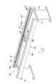
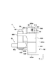
- FIG. 4 is an explanatory diagram of a transport mechanism.
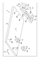
- the exploded perspective view of a pallet The exploded perspective view of a pallet.
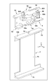
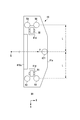
- FIG. 4 is an explanatory diagram of an arrangement of components of a driven unit. Explanatory drawing of arrangement
- FIG. 4 is a perspective view of a stop unit and a positioning unit.
- FIG. 3 is a perspective view of a stop unit.
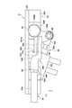
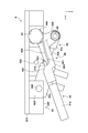
- FIG. 4 is an explanatory diagram of the operation of the stop unit.
- FIG. 4 is an explanatory diagram of an engagement operation of a movable member.
- FIG. 4 is an explanatory diagram of an arrangement of components of a driven unit.
- FIG. 13 is a perspective view of another example of a driven unit.
- FIG. 16 is an explanatory diagram of an arrangement of components of the driven unit in FIG. 15.
- arrows X and Y indicate horizontal directions orthogonal to each other, and arrow Z indicates a vertical direction.
- FIG. 1 is a perspective view of a work system 1 to which the present invention is applied.
- the work system 1 includes a gantry 2, a transfer device 3 for transferring a work (not shown), and a plurality of work devices 6.
- the transport device 3 includes a plurality of stop units 5.
- a work layout is formed by using a plurality of transfer devices 3 based on the work transfer specifications, and the working system is arranged by appropriately arranging the working device 6 at a predetermined position of the formed transfer layout. Be built.
- a configuration two in the example of FIG. 18 in which a plurality of the gantry 2 and the transfer device 3 of FIG. 1 are arranged in the Y direction may be constructed.
- the gantry 2 is a structure that supports the transport device 3 and the plurality of working devices 6.
- the gantry 2 includes a rectangular frame 20 and a base plate 21 supported on the frame 20.
- the transporting device 3 On the base plate 21, the transporting device 3, the respective stopping units 5, and the respective working devices 6 are installed.
- the transport device 3 is fixed to the base plate 21 via two leg members 8.
- Each stop unit 5 is fixed via a corresponding positioning unit 7.
- the transport device 3 includes a transport mechanism 3A, a pallet 4, and a plurality of stop units 5, and the transport mechanism 3A moves the pallet 4 in the Y direction, which is the workpiece transport direction.
- the pallet 4 includes a placing member 40 on which a work (not shown) to be worked is placed.
- FIG. 2 is an explanatory diagram of the transport mechanism 3A.
- the transport mechanism 3 ⁇ / b> A includes a pair of support frames 30 and 31 that define a transport trajectory of the pallet 4.
- the transport trajectory is a trajectory extending in the Y direction.
- the pair of support frames 30 and 31 extend in the Y direction in parallel with each other.
- the support frames 30 and 31 are separated from each other by a leg member 8 while being separated in the X direction, which is the width direction of the transfer device 3 (the width direction of the transfer track).
- the leg member 8 is a connecting member.
- the pair of support frames 30 and 31 are separate members. If it is desired to increase the width of the transport track, the distance between the support frames 30 and 31 in the X direction may be changed and these may be fixed to the leg member 8 or another connecting member corresponding to the leg member 8.
- the support frame 30 includes a frame body 30a and a guide 30b supported on the frame body 30a.
- the frame body 30a and the guide portion 30b extend in the Y direction.
- the guide section 30b has a rectangular cross section.
- the support frame 31 includes a frame main body 31a and a guide portion 31b supported on the frame main body 31a.
- the frame body 31a and the guide part 31b extend in the Y direction.
- the cross-sectional shape of the guide portion 31b is rectangular.
- the support frame 31 includes a support portion 31c that guides and supports movement of a drive transmission member 32c described below.
- the support portion 31c also extends in the Y direction.
- the support portion 31c guides a part of the inner peripheral surface of the drive transmission member 32c in the Y direction and a part of the side portion of the drive transmission member 32c in the Y direction.
- a second guide portion serving as a portion to be formed.
- the first guide portion guides the transmission member 32c while regulating the height thereof in the Y direction, and the second guide portion regulates the movement of the transmission member 32c in the width direction and guides the transmission member 32c in the Y direction.
- the support portion 31c may be provided integrally with the frame main body 31a, or may be provided separately.
- Each of the guide portions 30b and 31b guides the pallet 4 at a constant transport height.
- the guide portion 30b defines the transport height in the height direction (Z direction) on one side of the pallet 4 in the width direction
- the guide portion 31b defines the transport direction in the height direction (Z direction) on the other side of the pallet 4 in the width direction.
- the transfer height is specified.
- only the guide portion 31b functions as a transport guide portion in the width direction (X direction).
- the drive unit 32 is supported on the inner side surface of the support frame 31 that faces the frame body 30a of the frame body 31a.
- the drive unit 32 applies a conveying force to the pallet 4. That is, the pallet 4 is a driven body driven by the drive unit 32.
- the pallet 4 itself does not require a driving source such as a motor for moving the pallet. Thereby, the manufacturing cost of the pallet 4 can be reduced.
- the drive unit 32 is a belt transmission mechanism.
- the drive unit 32 includes a drive transmission member 32c which is an endless belt, a plurality of driven pulleys 32a and 32b, and a drive unit 32d.
- the drive unit 32d includes a motor as a drive source and a drive pulley (both not shown), and the drive transmission member 32c is wound around a drive pulley in the drive unit 32d and a plurality of driven pulleys 32a and 32b. It is turned and runs cyclically.
- the pallet 4 moves following the travel of the drive transmission member 32c.
- the driven pulleys 32b, 32b are rotatably supported at the respective ends of the frame body 31a in the Y direction, and the driven pulleys 32a, 32a are rotatably supported adjacent to each other at the center of the frame body 31a in the Y direction. Have been.
- the drive pulley (not shown) is rotatably supported at a position below the driven pulleys 32a, 32a in the frame body 31a.
- the drive transmission member 32c has an upper traveling portion extending from one driven pulley 32b to the other driven pulley 32b, and is guided by the support portion 31c while its height direction is defined.
- FIGS. 3 and 4 are exploded perspective views of the pallet 4 from different viewpoints.
- the pallet 4 is roughly divided into three units so that it can be disassembled and assembled.
- One of the three units is a mounting member 40, the other is a driven unit 41, and the other is an auxiliary unit 42.
- two auxiliary units 42 are provided.
- the driven unit 41 supports one wheel group (roller R1 described later) in the width direction of the pallet 4 (X direction in FIG. 1)
- the auxiliary unit 42 supports the other wheel group in the width direction of the pallet 4. By supporting the group (a roller R4 described later), the running stability of the pallet 4 is improved.
- the mounting member 40 is a member on which the work is mounted.
- the driven unit 41 is a traveling unit that travels along the guide portion 31b of the support frame 31 by receiving a conveying force from the driving unit 32.
- the auxiliary unit 42 is a traveling unit that is connected to the driven unit 41 via the mounting member 40 and that can travel along the guide portion 30b of the support frame 30.
- the mounting member 40 can be manufactured by a special design corresponding to the type of the work.
- the length of the mounting member 40 in the X and Y directions is designed according to the size of the work.
- the thickness (length in the Z direction) of the mounting member 40 can be designed according to the weight of the work.
- a protrusion, a depression, an opening (a hole or the like) and the like are provided on the mounting member 40 according to the shape of the work.
- the driven unit 41 and the auxiliary unit 42 are common parts that do not need to be designed according to the type of work, that is, are invariable parts whose design is not changed. Therefore, it is not necessary to redesign the entire pallet 4 every time the type of work changes, and the pallet 4 only needs to change the mounting member 40 prepared in advance according to the work to be conveyed. .
- the driven unit 41 and the auxiliary unit 42 can be regarded as the components of the pallet 4 and also the components of the transport mechanism 3A. That is, it can be said that the transport device 3 in the present embodiment is configured by the transport mechanism 3A and the pallet 4, and the transport mechanism 3A including the driven unit 41 and the auxiliary unit 42; It can also be said that it consists of.
- the pallet 4 including the driven unit 41 and the auxiliary unit 42 is formed by different transport mechanisms 3A in a system including a plurality of transport devices 3 arranged continuously as illustrated in FIG. Will move along the transport path.
- the mounting member 40 is a plate-shaped and rectangular member having a center of gravity position G as a whole, and a work is mounted on the upper surface thereof.
- the mounting member 40 has mounting holes 40a and 40b penetrating in the thickness direction.
- the mounting hole 40a is a hole for fixing the mounting member 40 and the driven unit 41, and the fixing member 43 is inserted therein.
- the fixing method is bolt fastening
- the fixing member 43 is a bolt.
- the fixing member 43 includes a head 43a and a screw shaft 43b, and the mounting hole 40a is a stepped hole having a large-diameter portion in which the head 43a is housed and a small-diameter portion into which the screw shaft 43b is inserted and screwed.
- the mounting hole 40b is a hole for fixing the mounting member 40 and the auxiliary unit 41.
- two auxiliary units 42 are provided apart from each other in the Y direction.
- two mounting holes 40b are also formed apart from each other in the Y direction.
- the fixing method is bolt fastening similarly to the driven unit 41, and the fixing member 43 is inserted into the mounting hole 40b.
- the mounting hole 40b is a stepped hole having a large-diameter portion in which the head 43a of the fixing member 43 is accommodated and a small-diameter portion into which the screw shaft 43b is screwed.
- an engaging portion 40c for positioning the driven unit 41 and an engaging portion 40d for positioning the auxiliary unit 42 are formed.
- the positioning structure is a fitting structure of a hole and a shaft, and each of the engaging portions 40c and 40d is a fitting hole having a lid.
- the driven unit 41 is provided with an engaging portion 41c corresponding to the engaging portion 40c, and the engaging portion 41c is a fitting shaft (fitting pin) fitted to the engaging portion 40c.
- the engaging portion 41c and the engaging portion 41c are provided apart from each other in the Y direction. That is, the driven unit 41 and the mounting member 40 are positioned at two positions, and more accurate positioning can be performed in both the X direction and the Y direction.
- the auxiliary unit 42 is provided with an engaging portion 42c corresponding to the engaging portion 40d, and the engaging portion 42c is a fitting body (fitting pin) fitted to the engaging portion 40d.
- FIG. FIG. 5 is an explanatory view showing the arrangement of the components of the driven unit 41 (the main body member 41a is shown by a virtual line).
- the driven unit 41 includes a plate-shaped main body member 41a.
- a mounting hole 41b and two engagement portions 41c are formed on the upper surface of the main body member 41a.
- the two engaging portions 41c are fitting shafts that are fitted to the engaging portions 40c to position the mounting member 40 and the driven unit 41.
- the mounting hole 41b is a hole for fixing the mounting member 40 and the driven unit 41.
- the mounting hole 41b is a screw hole, and the screw shaft 43b of the fixing member 43 that has passed through the mounting hole 40a (small diameter portion) of the mounting member 40 is screwed. Thereby, the mounting member 40 is fixed to the main body member 41a so as to overlap the upper surface of the main body member 41a.
- the main body member 41a has a plurality of openings 41d penetrating in the thickness direction thereof, and the rollers R1 are arranged in the respective openings 41d.
- the roller R1 is supported by a shaft fixed in the opening 41d and extending in the X direction.
- the roller R1 is rotatable with respect to the shaft.
- two pairs of the roller R1 and the opening 41d are provided, and are separated from each other in the transport direction (the Y direction in FIG. 5).
- the two rollers R1 are support rollers that contact the upper surface of the guide portion 31b, and are supported by the upper surface of the guide portion 31b from below, and roll on the guide portion 31b.
- rollers R2 and R3 are provided at a lower portion (bottom surface) of the main body member 41a so as to sandwich each opening 41d.
- the roller R2 is in contact with one side surface (outside guide surface) of the guide portion 31b
- the roller R3 is in contact with the other side surface (inside guide surface) of the guide portion 31b, in a direction perpendicular to the transport direction of the pallet 4 in the horizontal plane ( The position is regulated in the X direction in FIG.
- the rollers R2 and R3 are guide rollers rotatably supported by a shaft extending in the Z direction. Two sets of rollers R2 and R3 are provided apart from each other in the Y direction.
- the roller R2 and the roller R3 are arranged so as to be separated from each other in the X direction and face each other, and the gap between them is substantially equal to the width of the guide portion 31b. In other words, the rollers R2 and R3 are arranged so as to sandwich the guide portion 31b.
- a friction engagement unit 410 is also provided on the bottom surface of the main body member 41a.
- the friction engagement unit 410 is a unit that receives a conveying force from the drive unit 32.
- the friction engagement unit 410 presses the friction engagement member 410a downward (in the Z direction in FIG. 5), that is, the drive transmission member 32c, with the friction engagement member 410a abutting on the drive transmission member 32c.
- a pressing unit 410b has a built-in spring, and the frictional engagement member 410a is pressed against the drive transmission member 32c by the elastic force (biasing force) of the spring.
- the force of the friction engagement unit 410 pressing the friction engagement member 410a against the outer peripheral surface of the drive transmission member 32c is received by the support portion 31c.
- the drive transmission member 32c is sandwiched between the friction engagement member 410a and the support portion 31c.
- the elastic force of the spring of the pressing unit 410b is smaller than the weight of the pallet 4 and is within a range where a frictional force enough to move the pallet 4 can be obtained even when a work is placed on the pallet 4. Is set.
- An engagement portion 411 is provided on the bottom surface of the main body member 41a.
- the engaging portion 411 is disposed at one end in the X direction of the main body member 41a.
- the engaging portion 411 is a columnar body having a circular cross section.
- the engagement portion 411 may be a rolling member rotatable around the Z axis.
- the friction engagement unit 410 and the engagement portion 411 are provided between the two pairs of rollers R2 and R3 when viewed at the position in the Y direction.
- the two sets of rollers R2 and R3 are brought into contact with the guide portion 31b to restrict the displacement of the driven unit 41 in the X direction, when the transporting force is transmitted or when a temporary stopping force is applied.
- the inclination of the driven unit 41 around the X axis (pitching), the inclination around the Y axis (rolling), or the inclination around the Z axis (yawing) can be prevented, and the driven unit 41 moves or stops more stably. be able to.
- FIG. 6 is an explanatory diagram showing the arrangement of the components of the auxiliary unit 42 (the main body member 42a is shown by a virtual line).
- the auxiliary unit 42 includes a block-shaped main body member 42a.
- a mounting hole 42b and an engaging portion 42c are formed on the upper surface of the main body member 42a.
- the engaging portion 42c is a fitting pin that is fitted to the engaging portion 40d to position the mounting member 40 and the auxiliary unit 42.
- the mounting hole 42b is a mounting hole for fixing the mounting member 40 and the auxiliary unit 42.
- the mounting hole 42b is a screw hole, and the screw shaft 43b of the fixing member 43 that has passed through the mounting hole 40b of the mounting member 40 is screwed.
- the mounting member 40 is fixed to the main body member 42a so as to overlap the upper surface of the main body member 42a.
- the auxiliary unit 42 and the driven unit 41 are separably connected via the mounting member 40, and the pallet 4 is integrated as a whole.
- the case where the number of the auxiliary units 42 in the pallet 4 is two has been described as an example, but the number of the auxiliary units 42 is not particularly limited.
- the driven unit 41 may be left as it is, and the number of the auxiliary units 42 may be one.
- the auxiliary unit 42 is preferably provided at an intermediate portion in the transport direction (the Y direction in FIG. 3) on the mounting member 40 on the side of the frame main body 30a.
- a roller R4 is provided on the side surface of the main body member 42a.
- the roller R4 is rotatably supported by a shaft extending on a surface (the right side in FIG. 3) of the main body member 42a facing the driven unit 41 and extending in a direction orthogonal to the transport direction.
- the roller R4 contacts the upper surface of the guide portion 30b and rolls on the guide portion 30b.
- the driven unit 41 receives the transport force of the drive transmission member 32c, receives the temporary stop force of the stop unit 5, and further restricts displacement in the X direction. While the (rollers R2, R3) are performed, the auxiliary unit 42 only rolls on the guide portion 30b. That is, while the driven unit 41 has a configuration in which multiple functions are added, the auxiliary unit 42 has a simple configuration, so that the driving unit 32 and the driving unit 32 are provided on the support frame 31 side where the driven unit 41 is located.
- the stop unit 5 can be centrally arranged. This facilitates the study of the layout of the transport trajectory when a plurality of transport devices 3 are arranged side by side as shown in FIG. 18, and the alignment between the units can be performed in the support frame 31 and the driven unit 41. it can. Further, a space for arranging the working device 6 on the side of the auxiliary unit 42 and the support frame 30 can be easily secured.
- the working device 6 is a device that performs operations such as processing, assembling, and inspection on the work on the pallet 4.
- three working devices 6 are arranged along the transport direction (Y direction) of the transport device 3.
- Each working device 6 includes a working head 60 and a moving unit 61 that moves the working head 60.
- the moving unit 61 has a column shape extending in the Z direction, and stands upright on the installation part 21c.
- the moving unit 61 can move the working head 60 in the Z direction and the X direction.
- the work head 60 is a mechanism for performing work on a work.
- FIG. 7 is a perspective view (exploded perspective view) of the stop unit 5 and the positioning unit 7
- FIG. 8 is a perspective view of the stop unit 5
- FIG. 9 is a plan view of the stop unit 5
- FIG. 11 is a right side view of the stop unit 5
- FIG. 12 is an explanatory diagram of the operation of the stop unit 5
- FIG. 13 is an explanatory diagram of an engagement operation of the movable member 50. Note that the stop unit 5 described below is an example, and a stop unit having another configuration can be adopted.
- the positioning unit 7 is a member on which the stop unit 5 is installed and which positions the stop unit 5 with respect to the transport device 3.
- the positioning unit 7 is a member integrally provided with lower and upper mounting portions 71 and 72 and a vertical plate portion 73 connecting these.
- the mounting part 71 is a part for fixing the positioning unit 7 to the base plate 21 of the gantry 2.
- the fixing structure is, for example, bolt fastening.
- the mounting portion 72 is a portion to which the stop unit 5 is fixed, and the upper surface thereof forms a horizontal reference surface 72a.
- the reference surface 72a defines the position of the stop unit 5 in the Z direction.
- a reference engagement portion 73 is formed on the reference surface 72a.
- the reference engagement portion 73 is a pin-shaped shaft member protruding upward from the reference surface 72a.
- the reference engagement portion 73 defines the position of the stop unit 5 in the Y direction.
- the positioning unit 7 is fixed to the gantry 2 and the stop unit 5 is positioned with respect to the transport device 3.
- the positioning unit 7 may be fixed to the transport device 3 so that the stop unit 5 is positioned with respect to the transport device 3.
- the stop unit 5 is a device for temporarily stopping the pallet 4 by engaging with the engaging portion 411 of the pallet 4, and the engaging portion 411 of the pallet 4 is engaged with a concave portion 501 described later.
- the stop positions of the pallet 4 are positions corresponding to the work positions of the work devices 6, and are three places in the example of FIG. For this reason, a total of three stop units 5 are provided corresponding to each stop position.
- the pallet 4 is stopped at each stop position, so that the work position of each work device 6 is directly opposed to the work position of the work. Thereby, the work can be performed more accurately on the work.
- the stop unit 5 includes a movable member 50, a support member 52, and an actuator 53.
- the movable member 50 is a member that engages with the engaging portion 411 of the pallet 4 to temporarily stop the movement of the pallet 4 in the transport direction.
- the movable member 50 integrates the main body 500, the cylindrical portion 505, and the connecting portion 506. Prepare.
- the cylindrical portion 505 and the connecting portion 506 are located on the upstream side (one side) of the main body 500 in the transport direction of the pallet 4 (Y direction).
- the cylindrical portion 505 has a Z-direction shaft hole 505a (FIG. 13) into which the rotating shaft portion 54b (FIG. 10) of the shaft member 54 is inserted.
- the rotation shaft portion 54b is a shaft portion extending in the Z direction, and the shaft member 54 is supported by a support portion 520b provided on one side of the support member 52.
- the movable member 50 has a cylindrical portion 505 provided on one side supported by a support member 52 via a shaft member 54 so as to be rotatable around its axis 54a. Can be displaced between a disengaged position shown in FIG.
- the engagement position is a position where the other side of the movable member 50 separated from the cylindrical portion 505 engages with the engagement portion 411 of the pallet 4 to temporarily stop the pallet 4.
- the disengagement position is a position at which the other side of the movable member 50 separated from the cylindrical portion 505 disengages from the engagement portion 411 of the pallet 4 and makes the pallet 4 movable.
- the movable member 50 is rotated around the axis 54a, but may be moved in parallel.
- the stop unit 5 includes a shock absorber 51.
- the shock absorber 51 is fixed to the downstream end (the other side) of the main body 500 of the movable member 50.
- the shock absorber 51 is a cylinder damper, and includes a cylinder portion 51a and a rod portion 51b.
- a fluid that resists retraction of the rod portion 51b is sealed inside the cylinder portion 51a.
- the rod portion 51b has a contact portion 51c at the tip thereof, and the contact portion 51 protrudes into an inner space of the main body 500 surrounded by a concave portion 501 described later.
- the contact portion 51c is provided so as to protrude in the region of the contact portion of the concave portion 501 with which the engaging portion 411 of the pallet 4 contacts.
- the contact portion 51c is constantly urged so as to protrude into the region of the contact portion of the concave portion 501.
- the contact portion 51c retreats and enters the main body portion 500. Is done.
- the support member 52 is an L-shaped member integrally including the bottom wall 520 and the side wall 521.
- the bottom surface of the bottom wall portion 520 forms a defining portion 520a that is a surface that comes into contact with the reference surface 71a of the positioning unit 7.
- the position of the support member 52 in the Z direction (height position), that is, the position of the stop unit 5 in the Z direction (height direction) is defined by bringing the defining portion 520a into contact with the reference surface 71a.
- the bottom wall 520 is further provided with a defining portion 522 that engages with the reference engaging portion 73.
- the defining portion 522 is an engagement hole that passes through the bottom wall portion 520 in the thickness direction.
- the position of the support member 52 in the Y direction (position in the width direction), that is, the position of the stop unit 5 in the Y direction (width direction) is defined.
- the positioning unit 7 and the support member 52 are defined by the relationship between the reference surface 71a and the defining portion 520a and the relationship between the reference engaging portion 73 and the defining portion 522.
- the fastening unit (for example, a bolt and a nut) for fastening the texture unit 7 and the support member 52 may be fastened.
- the outer side surface of the side wall portion 521 that is in contact with the frame main body 31a forms a defining portion 521a that is a surface that is in contact with the outer side surface of the frame main body 31a.
- the side wall portion 521 is provided with a plurality of mounting holes 523 penetrating in the thickness direction thereof. A bolt (not shown) is inserted into the mounting hole 523, and a fastened portion (tapped hole or nut) prepared in the frame main body 31a is provided. ), The stop unit 5 is fixed to the frame main body 31a of the transport device 3.
- the positions of the stop unit 5 in the X, Y, and Z directions with respect to the transport trajectory of the pallet 4 are defined by the defining units 521a, 522, and 520a. Even when the stop unit 5 needs to be replaced due to wear, failure, or the like, the replacement is performed by the defining units 521a, 522, and 520a, making adjustment work for re-positioning the stop unit 5 substantially unnecessary. be able to.
- a bolt is inserted into the attachment hole 523, and the stop unit 5 is fixed to the transport device 3.
- the position of the stop unit 5 after replacement can be adjusted to the same position as the position of the stop unit 5 before replacement. Since the position before the replacement of the stop unit 5 and the position after the replacement can be re-aligned to the same position, it is not necessary to reset the work position of the work on the pallet 4 by the work device 6.
- a support portion 524 that supports a drive unit (actuator 53) described below that operates the movable member 50 is integrally formed on the bottom wall portion 520. Since the supporting portions 520b and 524 are formed integrally with the supporting member 52 together with the defining portions 521a, 522 and 520a, their mutual positional accuracy can be improved.
- the support portion 524 is formed as a pair perpendicular to the side wall portion 521 and spaced apart in the Z direction, and a shaft member 525 extending in the Z direction is fixed between the support members 524.
- the shaft member 525 has a rotation shaft portion 525b that extends in the Z direction and serves as a rotation center when one of the actuators 53 as a drive unit swings.
- the rotation shaft portion 525b is spaced downstream from the rotation shaft portion 54b of the shaft member 54 and a recess 501 described later, that is, on the other side of the support member 52, in the transport direction (Y direction) of the pallet 4, and is spaced apart from the support portion 520b.
- the actuator 53 is supported by the support member 52 so as to be rotatable around the axis 525a of the rotation shaft 525b.
- the actuator 53 as a drive unit is a fluid cylinder such as an air cylinder.
- the actuator 53 includes a driving unit 53a, a rod unit 53b, and an operation unit 53c.
- the driving part 53a moves the rod part 53b forward and backward in the axial direction by taking in and out of the fluid.
- the driving section 53a includes an insertion section in which a shaft hole through which the rotation shaft section 525b is inserted is formed.
- the operating portion 53c is provided at the tip of the rod portion 53b, and is rotatably connected to the connecting portion 506 of the movable member 50 via the shaft member 55 around the shaft 55a.
- the operating portion 53c is moved by the forward / backward movement of the rod portion 53b with respect to the driving portion 53a, thereby rotating the movable member 50 about the axis 54a.
- the connecting portion of the operation portion 53c connected to the connecting portion 506 is rotated (rotated counterclockwise in FIG. 8) about the axis 54a with the advance (extension) of the rod portion 53b.
- the operating portion 53c that is, the shaft 55a is moved counterclockwise on the circumferential orbit of the shaft center 55a while maintaining the distance from the shaft center 54a constant. Accordingly, the drive unit 53a is rotated around the axis 525a.
- the actuator 53 When the actuator 53 is retracted (contracted), the movement is reverse to the movement described above.
- the contraction of the actuator 53 urges the movable member 50 to the engagement position shown in FIG. 9, and the extension of the actuator 53 displaces the movable member 50 to the engagement release position shown in FIG.
- the actuator 53 contracts, the movable member 50 is urged to the engagement position shown in FIG. 9, but is not locked at that position.
- 9 can be turned counterclockwise in FIG.
- the fluid cylinder is illustrated as the actuator 53, but other actuators such as an electric cylinder and an electromagnetic solenoid can be adopted.
- a concave portion 501 that is concave in the X direction is formed on the side of the main body 500 on the side of the transport device 3 so as to face the transport trajectory of the pallet 4.
- the concave portion 501 is a portion that engages with the engaging portion 411, and has a shape that matches the engaging portion 411.
- the cross-sectional shape of the engaging portion 411 is circular, the inner surface of the concave portion 501 that comes into contact with the engaging portion 411 has a C shape in plan view.
- a guide 502 is also formed on the side of the main body 500 on the side of the transport device 3.
- the guide portion 502 of the present embodiment is an inclined surface extending from the concave portion 501 to the upstream side in the transport direction (Y direction). With reference to the case where the movable member 50 is at the engagement position, the guide portion 502 moves in the X direction so that it is relatively far from the transport device 3 on the upstream side in the transport direction and relatively close to the transport device 3 on the downstream side. It is a continuous surface that is connected to the concave portion 501 while being inclined.
- the concave part 501 is a continuous inclined surface that gradually separates in the direction away from the movement trajectory of the engaging portion 411 of the pallet 4 that moves the transfer device 3 in the transfer direction (Y direction).
- the deepest part (outer end in the X direction) of the concave part 501 is formed deeper than the downstream end of the guide part 502 (located outside in the X direction).
- An avoidance section 503 is formed on the side of the main body 500 on the side of the transport device 3.
- the avoiding portion 503 of the present embodiment is an inclined surface extending from the concave portion 501 to the downstream side in the transport direction (Y direction).
- the avoiding unit 503 is configured to move in the X direction so as to be relatively far from the transport device 3 on the upstream side in the transport direction and relatively close to the transport device 3 on the downstream side. It is a continuous surface extending from the downstream end of the concave portion 501 while being inclined.
- the deepest portion (outer end in the X direction) of the concave portion 501 is deeper than the upstream end of the avoidance portion 503 (located outside in the X direction).
- the state ST1 indicates a state immediately before the movable member 50 is at the engagement position, the pallet 4 is conveyed to the conveyance device 3, and the engagement portion 411 reaches the movable member 50.
- the chain double-dashed line indicates the movement trajectory T of the engaging portion 411 due to the transport of the pallet 4. Due to the above inclination, the guide portion 502 is located at a position away from the movement trajectory T on the upstream side, at a position approaching the movement trajectory T on the downstream side, and at a position on the movement trajectory T at an intermediate portion thereof.
- State ST2 indicates a state in which the conveyance of the pallet 4 has progressed.
- the pallet 4 is transported by surface engagement (frictional force) between the friction engagement member 410a and the outer peripheral surface of the drive transmission member 32c.
- the pallet 4 is transported from the upstream side (right side in the figure) to the downstream side (left side in the figure) as the drive transmission member 32c moves.
- the engaging portion 411 interferes with the guide portion 502.
- the pallet 4 receives a force F on the inside (toward the support frame 30) in the X direction.
- the engaging portion 411 presses the movable member 50 outward.
- the engaging portion 411 is at a position equidistant L from the roller R2 on the downstream side and the roller R2 on the upstream side in the transport direction. Since a triangle (in the present embodiment, an isosceles triangle) is formed and is in a stable state, it is possible to more reliably suppress the pallet 4 from tilting or meandering when receiving the force F.
- the position G of the center of gravity of the mounting member 40 is the same position as the position of the engaging portion 411 in the Y direction, and the line of action of the force F passes through the position G of the center of gravity or its vicinity. This further enhances the effect of suppressing the pallet 4 from tilting or meandering.
- the pallet 4 conveyed from the upstream side to the downstream side has the engaging portion 411 abutting on the guide portion 502, and the inclined portion of the guide portion 502 causes the engaging portion 411 to be gradually moved to the center side of the conveying device 3.
- the movement of the engaging portion 411 to the center side is defined by the rollers R2 and R2 of the pallet 4 abutting against the side surfaces of the guide portion 31b and the movement to the center side is regulated.
- the movement in the width direction is restricted).
- the engaging portion 411 moves together with the pallet 4, the contact force between the inclined surface of the guide portion 502 and the engaging portion 411 becomes larger than the urging force of the actuator 53, and the movable member 50 In the same manner, it rotates counterclockwise from the engagement position shown by the dotted line to the position shown by the solid line in FIG.
- the conveying force of the pallet 4 due to the friction force between the friction engagement member 410a and the drive transmission member 32c is larger than the urging force of the actuator 53.
- the engaging portion 411 gets over the guide portion 502 and enters the concave portion 501.
- the movable member 50 returns to the engagement position by the bias of the actuator 53.
- the concave portion 501 and the engaging portion 411 are engaged, and the pallet 4 is held between the driven unit 41 and the guide portion 31b, stopped at the stop position, and positioned and held. Is done.
- the engaging portion 411 comes into contact with the contact portion 51c of the shock absorber 51, and pushes the rod portion 51b toward the cylinder portion 51a.
- the shock at the time of engagement between the concave portion 501 and the engagement portion 411 is reduced.
- the concave portion 501 has a C-shape conforming to the shape of the engaging portion 411, and its deepest portion is located outside the upstream end as described above. For this reason, not only the movement of the engaging portion 411 to the downstream side, but also the movement to the upstream side, and the back of the pallet 4 to the upstream side due to the recoil at the time of engagement is also restricted.
- the pallet 4 By the engagement between the engaging portion 411 and the concave portion 501, the pallet 4 temporarily stops and the holding of the pallet 4 is completed. At this time, the drive transmission member 32c slides on the friction engagement member 410a.
- the pallet 4 can be temporarily stopped and held by one movable member 50, and the back of the pallet 4 due to the recoil when stopped can be restricted. Therefore, the number of members can be reduced and the pallet 4 can be temporarily stopped and held for a mechanism that realizes these with a plurality of members.
- the mounting member 40 may be newly designed corresponding to the work, and the driven unit 41 and the auxiliary unit 42 do not need to be redesigned.
- the existing driven unit 41 and the auxiliary unit 42 can be used.
- the drive unit 32 and the stop unit 5 are provided intensively on the support frame 31 side, and the driven unit 41 is provided with a configuration corresponding to these.
- the driven unit 41 is also provided with rollers R2 and R3 that regulate the displacement of the pallet 4 in the X direction. Provided. Therefore, there is almost no need to adjust the position of the device after changing the specifications.
- the drive unit 32 is arranged inside (the support frame 30 side) and the stop unit 5 is arranged outside (opposite side) with respect to the support frame 31, sufficient space for disposing them can be secured.
- the frictional engagement member 410a (the frictional engagement unit 410) with respect to the rolling center line XR of the two rollers R1.
- the engaging portions 411 are arranged on the outside, so that the driven unit 41 can secure a sufficient space for disposing them.
- ⁇ Second embodiment> By detecting that the pallet 4 has reached the stop position, the timing at which the working device 6 starts to work on the work can be used as a guide. Therefore, a sensor for detecting that the pallet 4 has reached the stop position may be provided. In this case as well, by arranging the sensor on the support frame 31 and providing the driven unit 41 with the detected part to be detected by the sensor, alignment and the like at the time of specification change become easy.
- FIG. 15 is a perspective view showing an example of the driven unit 41 provided with the detection unit 412.
- the detected part 412 is fixed to the inner side surface of the main body member 41a.
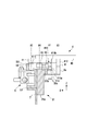
- FIG. 16 is a cross-sectional view showing an example of the arrangement of the sensor 9 for detecting the detection target 412.
- the sensor 9 is, for example, an optical sensor or a magnetic sensor, and detects whether or not the detection target 412 exists immediately above the sensor.
- the sensor 9 is fixed to the frame main body 31a of the support frame 31 via a bracket 9a at a position corresponding to the stop position of the work.
- the position of the detected part 412 in the X direction needs to be appropriately set with respect to the stop unit 5, the guide part 31b, and the like.
- the rotation center X0 of the roller R2 is set as a reference position, and the position X2 of the contact portion 411, the position X1 of the friction engagement unit 410, The position X3 of the part 412 can be determined. Since these are all determined in the driven unit 41, there is no need for position adjustment when assembling the transport device 3.
- FIG. 17 illustrates another configuration example of the pallet 4.
- the illustrated example is a configuration example of the pallet 4 suitable for a relatively large work.
- Six auxiliary units 42 are provided. Two of them are arranged before and after the driven unit 41 and run on the support unit 31 (not shown in the figure), and the remaining four auxiliary units 42 are supported by the support unit 30 (not shown in the figure). (Shown).
- the driven unit 41 and the auxiliary unit 42 do not need to be redesigned. Only the placing member 40 has to be newly designed.
Landscapes
- Engineering & Computer Science (AREA)
- Mechanical Engineering (AREA)
- Automatic Assembly (AREA)
- Reciprocating Conveyors (AREA)
- Intermediate Stations On Conveyors (AREA)
Abstract
Description
互いに平行に設けられ、ワークが載置される載置部材を含むパレットの搬送軌道を画定する一対の第一の支持フレーム及び第二の支持フレームと、
前記第一の支持フレームに設けられ、前記パレットに搬送力を付与する駆動ユニットと、
前記パレットを構成するユニットであって、前記駆動ユニットから前記搬送力を受けて前記第一の支持フレームの第一のガイド部に沿って走行する被駆動ユニットと、
前記パレットを構成するユニットであって、前記載置部材を介して前記被駆動ユニットと連結され、前記第二の支持フレームの第二のガイド部に沿って走行自在な補助ユニットと、
前記第一の支持フレームに設けられ、前記被駆動ユニットの一部と係合する係合部を含むとともに、前記搬送軌道に沿った所定の停止位置で前記パレットの移動を一時的に停止させる停止ユニットと、を備える、
ことを特徴とする搬送装置が提供される。
搬送機構によって搬送されるパレットを構成する被駆動ユニットであって、
前記搬送機構は、
互いに平行に設けられ、ワークが載置される載置部材を含む前記パレットの搬送軌道を画定する一対の第一の支持フレーム及び第二の支持フレームと、
前記第一の支持フレームに設けられ、前記パレットに搬送力を付与する駆動ユニットと、
前記第一の支持フレームに設けられ、前記パレットの一部と係合する係合部を含むとともに、前記搬送軌道に沿った所定の停止位置で前記パレットの移動を一時的に停止させる停止ユニットと、を備え、
前記被駆動ユニットは、前記駆動ユニットから前記搬送力を受けて前記第一の支持フレームの第一のガイド部に沿って走行するユニットであり、
前記パレットは、前記被駆動ユニットと、前記載置部材と、前記載置部材を介して前記被駆動ユニットと連結され、前記第二の支持フレームの第二のガイド部に沿って走行自在な補助ユニットと、を備え、
前記被駆動ユニットは、
前記載置部材が固定される本体部材と、
前記本体部材に対して回転自在に設けられ、前記第一のガイド部と当接する複数のローラと、
前記本体部材の下部に設けられ、前記駆動ユニットと摩擦係合して搬送力を受ける第一の係合部と、
前記本体部材に設けられ、前記停止ユニットの前記係合部と係合する第二の係合部と、を備える、
ことを特徴とする被駆動ユニットが提供される。
前記搬送機構は、
互いに平行に設けられ、ワークが載置される載置部材を含む前記パレットの搬送軌道を画定する一対の第一の支持フレーム及び第二の支持フレームと、
前記第一の支持フレームに設けられ、前記パレットに搬送力を付与する駆動ユニットと、
前記第一の支持フレームに設けられ、前記パレットの一部と係合する係合部を含むとともに、前記搬送軌道に沿った所定の停止位置で前記パレットの移動を一時的に停止させる停止ユニットと、を備え、
前記パレットは、前記駆動ユニットから前記搬送力を受けて前記第一の支持フレームの第一のガイド部に沿って走行する被駆動ユニットと、前記載置部材と、前記補助ユニットと、を備え、
前記補助ユニットは、前記載置部材を介して前記被駆動ユニットと連結され、前記第二の支持フレームの第二のガイド部に沿って走行自在なユニットであり、
前記補助ユニットは、
前記載置部材が固定される本体部材と、
前記本体部材に対して回転自在に設けられ、前記第二のガイド部と当接する少なくとも一つのローラを含む、
ことを特徴とする補助ユニットが提供される。
搬送機構により搬送されるパレットであって、
前記搬送機構は、
互いに平行に設けられ、前記パレットの搬送軌道を画定する一対の第一の支持フレームおよび第二の支持フレームと、
前記第一の支持フレームに設けられ、前記パレットに搬送力を付与する駆動ユニットと、
前記第一の支持フレームに設けられ、前記パレットの一部と係合する係合部を含むとともに、前記搬送軌道に沿った所定の停止位置で前記パレットの移動を一時的に停止させる停止ユニットと、を備え、
前記パレットは、
ワークが載置される載置部材と、
前記駆動ユニットから前記搬送力を受けて前記第一の支持フレームの第一のガイド部に沿って走行する被駆動ユニットと、
前記載置部材を介して前記被駆動ユニットと連結され、前記第二の支持フレームの第二のガイド部に沿って走行自在な補助ユニットと、を備え、
前記被駆動ユニットは、
前記載置部材が固定される第一の本体部材と、
前記第一の本体部材に対して回転自在に設けられ、前記第一のガイド部と当接する複数のローラと、
前記第一の本体部材の下部に設けられ、前記駆動ユニットと摩擦係合して前記搬送力を受ける第一の係合部と、
前記第一の本体部材に設けられ、前記停止ユニットの前記係合部と係合する第二の係合部と、を備え、
前記補助ユニットは、
前記載置部材が固定される第二の本体部材と、
前記第二の本体部材に対して回転自在に設けられ、前記第二のガイド部と当接する少なくとも一つのローラと、を備える、
ことを特徴とするパレットが提供される。
<作業システム>
図1は本発明を適用した作業システム1の斜視図である。作業システム1は、架台2、ワーク(不図示)を搬送する搬送装置3及び複数の作業装置6を含む。搬送装置3は、複数の停止ユニット5を含む。実際の工場等においては、ワークの搬送仕様に基づいて、複数の搬送装置3を用いて搬送レイアウトを形成し、形成された搬送レイアウトの所定の位置に作業装置6を適宜配置させて作業システムが構築される。例えば、図18のレイアウト例のように、図1の架台2、搬送装置3をY方向に複数配置する構成(図18の例では2つ)も構築され得る。
本発明の一実施形態に係る搬送装置3は、搬送機構3Aとパレット4と複数の停止ユニット5を備え、搬送機構3Aはパレット4をワークの搬送方向となるY方向に移動させる。パレット4は、作業対象である不図示のワークが載置される載置部材40を含む。
図3及び図4を参照して本実施形態のパレット4の構造を説明する。図3及び図4は視点を変えた、パレット4の分解斜視図である。本実施形態の場合、パレット4は大別すると、3つのユニットから分解・組立自在に構成されている。3つのユニットの一つは、載置部材40であり、他の一つは被駆動ユニット41であり、残りの一つは補助ユニット42である。図示の例の場合、補助ユニット42は2つ設けられている。被駆動ユニット41が、パレット4の幅方向(図1中ではX方向)における一方側の輪群(後述するローラR1)を支持し、補助ユニット42が、パレット4の幅方向における他方側の輪群(後述するローラR4)を支持することで、パレット4の走行安定性を向上する。
図1を参照して作業装置6について説明する。作業装置6はパレット4上のワークに対して、加工、組み付け、検査等の作業を行う装置である。本実施形態では、搬送装置3の搬送方向(Y方向)に沿って三つの作業装置6が配置されている。各作業装置6は、作業ヘッド60と、作業ヘッド60を移動する移動ユニット61とを含む。移動ユニット61はZ方向に延びる支柱形状を有しており、設置部21cに立設されている。移動ユニット61は作業ヘッド60をZ方向とX方向とに移動可能である。作業ヘッド60はワークに対する作業を行う機構である。
搬送装置3に設けられた停止ユニット5の構成について、図1、図7~図13を参照して説明する。図7は停止ユニット5と位置決めユニット7との斜視図(分解斜視図)、図8は停止ユニット5の斜視図、図9は停止ユニット5の平面図、図10は停止ユニット5の正面図、図11は停止ユニット5の右側面図、図12は停止ユニット5の動作説明図、図13は可動部材50の係合動作の説明図である。なお、以下に説明する停止ユニット5は一例であり、他の構成の停止ユニットも採用可能である。
以上の構成からなる搬送装置3においては、異なるワークへの適用の際の仕様変更にも容易に対応できる。すなわち、パレット4においては載置部材40をワークに対応して新たに設計すればよく、被駆動ユニット41及び補助ユニット42は改めて設計し直す必要はない。既存の被駆動ユニット41及び補助ユニット42の流用も可能である。
パレット4が停止位置に到達したことを検知することで、作業装置6がワークに対する作業を開始するタイミングの目安となる。そこで、パレット4が停止位置に到達したことを検知するセンサを設けてもよい。この場合も、支持フレーム31にセンサを配置し、被駆動ユニット41にセンサが検知する被検知部を設けることで、仕様変更時の位置合わせ等が容易になる。
パレット4における被駆動ユニット41及び補助ユニット42の数や位置は適宜選択できる。図17はパレット4の他の構成例を例示している。図示の例は比較的大型のワークに適したパレット4の構成例である。補助ユニット42は6つ設けられている。そのうちの2つは、被駆動ユニット41の前後に配置され、支持ユニット31(同図で不図示)上を走行する構成であり、残りの4つの補助ユニット42が支持ユニット30(同図で不図示)上を走行する構成である。ワークの種類の変更により、パレット4の仕様変更の必要が生じた場合、このような仕様変更も可能であり、この場合も、被駆動ユニット41及び補助ユニット42を改めて設計する必要はなく、載置部材40のみを新たに設計すればよいことになる。
Claims (12)
- 互いに平行に設けられ、ワークが載置される載置部材を含むパレットの搬送軌道を画定する一対の第一の支持フレーム及び第二の支持フレームと、
前記第一の支持フレームに設けられ、前記パレットに搬送力を付与する駆動ユニットと、
前記パレットを構成するユニットであって、前記駆動ユニットから前記搬送力を受けて前記第一の支持フレームの第一のガイド部に沿って走行する被駆動ユニットと、
前記パレットを構成するユニットであって、前記載置部材を介して前記被駆動ユニットと連結され、前記第二の支持フレームの第二のガイド部に沿って走行自在な補助ユニットと、
前記第一の支持フレームに設けられ、前記被駆動ユニットの一部と係合する係合部を含むとともに、前記搬送軌道に沿った所定の停止位置で前記パレットの移動を一時的に停止させる停止ユニットと、を備える、
ことを特徴とする搬送装置。 - 請求項1に記載の搬送装置であって、
前記被駆動ユニットは、
前記載置部材が固定される本体部材と、
前記本体部材に対して回転自在に設けられ、前記第一のガイド部に当接する複数のローラと、
前記本体部材の下部に設けられ、前記駆動ユニットと摩擦係合して前記搬送力を受ける第一の係合部と、
前記本体部材に設けられ、前記停止ユニットの前記係合部と係合する第二の係合部と、を備える、
ことを特徴とする搬送装置。 - 請求項2に記載の搬送装置であって、
前記第一のガイド部は、前記搬送軌道の幅方向で外側のガイド面と内側のガイド面とを含み、
前記複数のローラは、上下方向の軸回りに回転自在に前記本体部材の下面に設けられた複数のガイドローラを含み、
前記複数のガイドローラは、前記外側のガイド面に当接する外側のガイドローラと、前記内側のガイド面に当接する内側のガイドローラとを含む、
ことを特徴とする搬送装置。 - 請求項1に記載の搬送装置であって、
前記被駆動ユニットが前記所定の停止位置に到達したことを検知するセンサを更に備え、
前記被駆動ユニットは、前記センサに検知される検知部を含む、
ことを特徴とする搬送装置。 - 搬送機構によって搬送されるパレットを構成する被駆動ユニットであって、
前記搬送機構は、
互いに平行に設けられ、ワークが載置される載置部材を含む前記パレットの搬送軌道を画定する一対の第一の支持フレーム及び第二の支持フレームと、
前記第一の支持フレームに設けられ、前記パレットに搬送力を付与する駆動ユニットと、
前記第一の支持フレームに設けられ、前記パレットの一部と係合する係合部を含むとともに、前記搬送軌道に沿った所定の停止位置で前記パレットの移動を一時的に停止させる停止ユニットと、を備え、
前記被駆動ユニットは、前記駆動ユニットから前記搬送力を受けて前記第一の支持フレームの第一のガイド部に沿って走行するユニットであり、
前記パレットは、前記被駆動ユニットと、前記載置部材と、前記載置部材を介して前記被駆動ユニットと連結され、前記第二の支持フレームの第二のガイド部に沿って走行自在な補助ユニットと、を備え、
前記被駆動ユニットは、
前記載置部材が固定される本体部材と、
前記本体部材に対して回転自在に設けられ、前記第一のガイド部と当接する複数のローラと、
前記本体部材の下部に設けられ、前記駆動ユニットと摩擦係合して搬送力を受ける第一の係合部と、
前記本体部材に設けられ、前記停止ユニットの前記係合部と係合する第二の係合部と、を備える、
ことを特徴とする被駆動ユニット。 - 請求項5に記載の被駆動ユニットであって、
前記本体部材は、開口部を有し、
前記複数のローラは、
上下方向の軸回りに回転自在に前記本体部材の下部に設けられ、前記搬送軌道の幅方向での前記被駆動ユニットの移動を規制する複数のガイドローラと、
左右方向の軸回りに回転自在に前記開口部内に配置され、前記第一のガイド部によって下方から支持される複数の支持ローラと、を含む、
ことを特徴とする被駆動ユニット。 - 請求項5に記載の被駆動ユニットであって、
前記複数のローラは、前記搬送軌道の方向に離間した第一のガイドローラ及び第二のガイドローラを含み、
前記第二の係合部の前記搬送軌道の方向の位置は、前記第一のガイドローラと前記第二のガイドローラとの間の位置である、
ことを特徴とする被駆動ユニット。 - 請求項7に記載の被駆動ユニットであって、
前記搬送軌道の方向における前記載置部材の重心位置が、前記第二の係合部の前記搬送軌道の方向の位置と同じ位置である、
ことを特徴とする被駆動ユニット。 - 請求項5に記載の被駆動ユニットであって、
前記被駆動ユニットが前記所定の停止位置に到達したことを検知するセンサに検知される検知部を含む、
ことを特徴とする被駆動ユニット。 - 請求項5に記載の被駆動ユニットであって、
前記複数のローラは、前記搬送軌道の方向に離間した第一のガイドローラ及び第二のガイドローラを含み、
前記第一の係合部の前記搬送軌道の方向の位置は、前記第一のガイドローラと前記第二のガイドローラとの間の位置である、
ことを特徴とする被駆動ユニット。 - 搬送機構によって搬送されるパレットを構成する補助ユニットであって、
前記搬送機構は、
互いに平行に設けられ、ワークが載置される載置部材を含む前記パレットの搬送軌道を画定する一対の第一の支持フレーム及び第二の支持フレームと、
前記第一の支持フレームに設けられ、前記パレットに搬送力を付与する駆動ユニットと、
前記第一の支持フレームに設けられ、前記パレットの一部と係合する係合部を含むとともに、前記搬送軌道に沿った所定の停止位置で前記パレットの移動を一時的に停止させる停止ユニットと、を備え、
前記パレットは、前記駆動ユニットから前記搬送力を受けて前記第一の支持フレームの第一のガイド部に沿って走行する被駆動ユニットと、前記載置部材と、前記補助ユニットと、を備え、
前記補助ユニットは、前記載置部材を介して前記被駆動ユニットと連結され、前記第二の支持フレームの第二のガイド部に沿って走行自在なユニットであり、
前記補助ユニットは、
前記載置部材が固定される本体部材と、
前記本体部材に対して回転自在に設けられ、前記第二のガイド部と当接する少なくとも一つのローラを含む、
ことを特徴とする補助ユニット。 - 搬送機構により搬送されるパレットであって、
前記搬送機構は、
互いに平行に設けられ、前記パレットの搬送軌道を画定する一対の第一の支持フレームおよび第二の支持フレームと、
前記第一の支持フレームに設けられ、前記パレットに搬送力を付与する駆動ユニットと、
前記第一の支持フレームに設けられ、前記パレットの一部と係合する係合部を含むとともに、前記搬送軌道に沿った所定の停止位置で前記パレットの移動を一時的に停止させる停止ユニットと、を備え、
前記パレットは、
ワークが載置される載置部材と、
前記駆動ユニットから前記搬送力を受けて前記第一の支持フレームの第一のガイド部に沿って走行する被駆動ユニットと、
前記載置部材を介して前記被駆動ユニットと連結され、前記第二の支持フレームの第二のガイド部に沿って走行自在な補助ユニットと、を備え、
前記被駆動ユニットは、
前記載置部材が固定される第一の本体部材と、
前記第一の本体部材に対して回転自在に設けられ、前記第一のガイド部と当接する複数のローラと、
前記第一の本体部材の下部に設けられ、前記駆動ユニットと摩擦係合して前記搬送力を受ける第一の係合部と、
前記第一の本体部材に設けられ、前記停止ユニットの前記係合部と係合する第二の係合部と、を備え、
前記補助ユニットは、
前記載置部材が固定される第二の本体部材と、
前記第二の本体部材に対して回転自在に設けられ、前記第二のガイド部と当接する少なくとも一つのローラと、を備える、
ことを特徴とするパレット。
Priority Applications (8)
| Application Number | Priority Date | Filing Date | Title |
|---|---|---|---|
| MYPI2020007078A MY201853A (en) | 2018-07-05 | 2018-07-05 | Conveyance device, driven unit, auxiliary unit, and pallet |
| JP2019521491A JP6764530B2 (ja) | 2018-07-05 | 2018-07-05 | 搬送装置、被駆動ユニット、補助ユニット及びパレット |
| CN201880095287.7A CN112384455B (zh) | 2018-07-05 | 2018-07-05 | 搬送装置、被驱动单元、辅助单元及托盘 |
| SG11202013093WA SG11202013093WA (en) | 2018-07-05 | 2018-07-05 | Transport device, driven unit, auxiliary unit, and pallet |
| EP18925132.5A EP3812315A4 (en) | 2018-07-05 | 2018-07-05 | TRANSPORT DEVICE, DRIVEN UNIT, AUXILIARY UNIT AND PALLET |
| PCT/JP2018/025592 WO2020008607A1 (ja) | 2018-07-05 | 2018-07-05 | 搬送装置、被駆動ユニット、補助ユニット及びパレット |
| KR1020207036847A KR102456611B1 (ko) | 2018-07-05 | 2018-07-05 | 반송 장치, 피구동 유닛 및 파렛트 |
| US17/136,182 US11396429B2 (en) | 2018-07-05 | 2020-12-29 | Conveyance device, driven unit, auxiliary unit, and pallet |
Applications Claiming Priority (1)
| Application Number | Priority Date | Filing Date | Title |
|---|---|---|---|
| PCT/JP2018/025592 WO2020008607A1 (ja) | 2018-07-05 | 2018-07-05 | 搬送装置、被駆動ユニット、補助ユニット及びパレット |
Related Child Applications (1)
| Application Number | Title | Priority Date | Filing Date |
|---|---|---|---|
| US17/136,182 Continuation US11396429B2 (en) | 2018-07-05 | 2020-12-29 | Conveyance device, driven unit, auxiliary unit, and pallet |
Publications (1)
| Publication Number | Publication Date |
|---|---|
| WO2020008607A1 true WO2020008607A1 (ja) | 2020-01-09 |
Family
ID=69060458
Family Applications (1)
| Application Number | Title | Priority Date | Filing Date |
|---|---|---|---|
| PCT/JP2018/025592 Ceased WO2020008607A1 (ja) | 2018-07-05 | 2018-07-05 | 搬送装置、被駆動ユニット、補助ユニット及びパレット |
Country Status (8)
| Country | Link |
|---|---|
| US (1) | US11396429B2 (ja) |
| EP (1) | EP3812315A4 (ja) |
| JP (1) | JP6764530B2 (ja) |
| KR (1) | KR102456611B1 (ja) |
| CN (1) | CN112384455B (ja) |
| MY (1) | MY201853A (ja) |
| SG (1) | SG11202013093WA (ja) |
| WO (1) | WO2020008607A1 (ja) |
Families Citing this family (5)
| Publication number | Priority date | Publication date | Assignee | Title |
|---|---|---|---|---|
| CN111216234B (zh) * | 2020-02-28 | 2025-06-10 | 民航机场建设工程有限公司 | 用于预制箱梁腹部钢筋架的加工设备 |
| CN113732350B (zh) * | 2021-08-23 | 2023-12-08 | 重庆永生压铸有限责任公司 | 一种铝合金轮毂自动钻孔系统 |
| CN114162531A (zh) * | 2021-12-15 | 2022-03-11 | 江苏新惕姆智能装备有限公司 | 输送装置、其输送方法、推送机构及组装线 |
| CN115557179A (zh) * | 2022-10-12 | 2023-01-03 | 江苏立讯机器人有限公司 | 治具往返输送装置及生产线 |
| DE102023119475A1 (de) * | 2023-07-24 | 2025-01-30 | EPA Gbr (vertretungsberechtigte Gesellschafter: Georg Leiritz, 91788 Pappenheim und Otto Leiritz, 91788 Pappenheim) | Werkstückträgersystem |
Citations (8)
| Publication number | Priority date | Publication date | Assignee | Title |
|---|---|---|---|---|
| JPS5934972A (ja) * | 1982-08-24 | 1984-02-25 | 株式会社椿本チエイン | パレツト搬送装置 |
| JPS62161114U (ja) * | 1986-04-04 | 1987-10-13 | ||
| JPH0356138U (ja) | 1989-10-04 | 1991-05-30 | ||
| JPH03205213A (ja) * | 1989-12-29 | 1991-09-06 | Matsushita Electric Ind Co Ltd | パレット規正装置 |
| JP2601873Y2 (ja) | 1992-04-17 | 1999-12-06 | 松下電器産業株式会社 | パレットコンベアのパレット位置決め装置 |
| JP2005028459A (ja) | 2003-07-07 | 2005-02-03 | Fuji Photo Film Co Ltd | 搬送パレット |
| JP2008133130A (ja) * | 2006-11-27 | 2008-06-12 | Hiroshima Ryoju Engineering Kk | シート積層体搬送装置 |
| JP2014091613A (ja) * | 2012-11-02 | 2014-05-19 | Hirata Corp | 搬送装置 |
Family Cites Families (9)
| Publication number | Priority date | Publication date | Assignee | Title |
|---|---|---|---|---|
| US3818837A (en) * | 1972-10-06 | 1974-06-25 | Si Handling Systems | Vehicle and track system |
| US4428300A (en) * | 1981-12-14 | 1984-01-31 | Si Handling Systems, Inc. | Vehicle precision stop assembly |
| US4691641A (en) * | 1986-02-21 | 1987-09-08 | Si Handling Systems, Inc. | Vehicle accumulation system |
| US4793261A (en) * | 1987-02-11 | 1988-12-27 | Durr Industries, Inc. | Accumulating pallet chain-dog conveyor and method of conveying pallets |
| US4964343A (en) * | 1987-07-15 | 1990-10-23 | Tsubakimoto Chain Co. | Pallet in frictionally driven roller type transfer apparatus |
| JP2601873B2 (ja) | 1988-04-30 | 1997-04-16 | 鹿島建設株式会社 | 長尺部材の配設機械 |
| JP2788293B2 (ja) | 1989-07-21 | 1998-08-20 | 東京濾器株式会社 | 排気ガス浄化用触媒 |
| DE19543797A1 (de) * | 1995-11-24 | 1997-05-28 | Grob Gmbh & Co Kg | Vorrichtung für die Steuerung einer Palette auf einer Förderbahn |
| CN103803251B (zh) * | 2012-11-02 | 2016-05-25 | 平田机工株式会社 | 输送系统及作业系统 |
-
2018
- 2018-07-05 MY MYPI2020007078A patent/MY201853A/en unknown
- 2018-07-05 JP JP2019521491A patent/JP6764530B2/ja active Active
- 2018-07-05 WO PCT/JP2018/025592 patent/WO2020008607A1/ja not_active Ceased
- 2018-07-05 SG SG11202013093WA patent/SG11202013093WA/en unknown
- 2018-07-05 CN CN201880095287.7A patent/CN112384455B/zh active Active
- 2018-07-05 EP EP18925132.5A patent/EP3812315A4/en active Pending
- 2018-07-05 KR KR1020207036847A patent/KR102456611B1/ko active Active
-
2020
- 2020-12-29 US US17/136,182 patent/US11396429B2/en active Active
Patent Citations (8)
| Publication number | Priority date | Publication date | Assignee | Title |
|---|---|---|---|---|
| JPS5934972A (ja) * | 1982-08-24 | 1984-02-25 | 株式会社椿本チエイン | パレツト搬送装置 |
| JPS62161114U (ja) * | 1986-04-04 | 1987-10-13 | ||
| JPH0356138U (ja) | 1989-10-04 | 1991-05-30 | ||
| JPH03205213A (ja) * | 1989-12-29 | 1991-09-06 | Matsushita Electric Ind Co Ltd | パレット規正装置 |
| JP2601873Y2 (ja) | 1992-04-17 | 1999-12-06 | 松下電器産業株式会社 | パレットコンベアのパレット位置決め装置 |
| JP2005028459A (ja) | 2003-07-07 | 2005-02-03 | Fuji Photo Film Co Ltd | 搬送パレット |
| JP2008133130A (ja) * | 2006-11-27 | 2008-06-12 | Hiroshima Ryoju Engineering Kk | シート積層体搬送装置 |
| JP2014091613A (ja) * | 2012-11-02 | 2014-05-19 | Hirata Corp | 搬送装置 |
Non-Patent Citations (1)
| Title |
|---|
| See also references of EP3812315A4 |
Also Published As
| Publication number | Publication date |
|---|---|
| MY201853A (en) | 2024-03-20 |
| KR102456611B1 (ko) | 2022-10-19 |
| CN112384455B (zh) | 2022-07-05 |
| CN112384455A (zh) | 2021-02-19 |
| US20210114815A1 (en) | 2021-04-22 |
| US11396429B2 (en) | 2022-07-26 |
| SG11202013093WA (en) | 2021-01-28 |
| EP3812315A4 (en) | 2021-07-07 |
| EP3812315A1 (en) | 2021-04-28 |
| JPWO2020008607A1 (ja) | 2020-07-16 |
| JP6764530B2 (ja) | 2020-09-30 |
| KR20210011439A (ko) | 2021-02-01 |
Similar Documents
| Publication | Publication Date | Title |
|---|---|---|
| JP6764530B2 (ja) | 搬送装置、被駆動ユニット、補助ユニット及びパレット | |
| JP6949114B2 (ja) | テーブル循環案内装置 | |
| TWI591006B (zh) | 多模式及多間距輸送機系統 | |
| TWI778738B (zh) | 曝光裝置、平板顯示器之製造方法及元件製造方法 | |
| KR101606259B1 (ko) | 트랜스퍼용 수평 운송 암 및 이 수평 운송 암이 적용된 트랜스퍼 로봇 | |
| CN103782239B (zh) | 基板处理装置及基板处理方法、曝光方法及曝光装置、以及元件制造方法、及平板显示器的制造方法 | |
| KR20180058798A (ko) | 노광 장치, 노광 방법, 플랫 패널 디스플레이의 제조 방법, 및 디바이스 제조 방법 | |
| KR20160013199A (ko) | 테이블 장치 및 반송 장치 | |
| US10466028B2 (en) | Coordinate measuring apparatus | |
| KR20160015329A (ko) | 테이블 장치 및 반송 장치 | |
| CN110114725A (zh) | 搬运装置、曝光装置、曝光方法、平板显示器的制造方法、元件制造方法以及搬运方法 | |
| KR101218772B1 (ko) | 유연기구를 이용한 회전 오차 보상 스테이지 | |
| KR20180059861A (ko) | 이동체 장치, 노광 장치, 플랫 패널 디스플레이의 제조 방법, 및 디바이스 제조 방법, 그리고 물체의 이동 방법 | |
| CN113424018B (zh) | 用于定位物体的定位系统 | |
| CN111895909B (zh) | 一种石膏板楔形边检测调整装置 | |
| JPH0839463A (ja) | 搬送装置 | |
| CN113167984B (zh) | 对准装置、透镜对准系统 | |
| JP6992151B2 (ja) | 停止装置、搬送装置及び作業システム | |
| JP2952166B2 (ja) | 門型駆動装置 | |
| JP2008103663A (ja) | 摩擦駆動搬送装置 | |
| JP5818241B2 (ja) | 球体駆動モジュール及びそれを用いた搬送装置 | |
| US6178836B1 (en) | Positioning apparatus | |
| JPH0858938A (ja) | パレット搬送装置 | |
| KR20150107047A (ko) | 피이송물의 정밀한 위치이송 및 회전가능한 볼어레이 이송장치 | |
| CN118486643B (zh) | 一种微转动载台及芯片巨量转移设备 |
Legal Events
| Date | Code | Title | Description |
|---|---|---|---|
| ENP | Entry into the national phase |
Ref document number: 2019521491 Country of ref document: JP Kind code of ref document: A |
|
| 121 | Ep: the epo has been informed by wipo that ep was designated in this application |
Ref document number: 18925132 Country of ref document: EP Kind code of ref document: A1 |
|
| ENP | Entry into the national phase |
Ref document number: 20207036847 Country of ref document: KR Kind code of ref document: A |
|
| NENP | Non-entry into the national phase |
Ref country code: DE |
|
| ENP | Entry into the national phase |
Ref document number: 2018925132 Country of ref document: EP Effective date: 20210125 |