WO2020008625A1 - Dispositif à cycle frigorifique - Google Patents
Dispositif à cycle frigorifique Download PDFInfo
- Publication number
- WO2020008625A1 WO2020008625A1 PCT/JP2018/025709 JP2018025709W WO2020008625A1 WO 2020008625 A1 WO2020008625 A1 WO 2020008625A1 JP 2018025709 W JP2018025709 W JP 2018025709W WO 2020008625 A1 WO2020008625 A1 WO 2020008625A1
- Authority
- WO
- WIPO (PCT)
- Prior art keywords
- pressure
- section
- refrigerant
- refrigeration cycle
- compressor
- Prior art date
- Legal status (The legal status is an assumption and is not a legal conclusion. Google has not performed a legal analysis and makes no representation as to the accuracy of the status listed.)
- Ceased
Links
Images



Classifications
-
- F—MECHANICAL ENGINEERING; LIGHTING; HEATING; WEAPONS; BLASTING
- F25—REFRIGERATION OR COOLING; COMBINED HEATING AND REFRIGERATION SYSTEMS; HEAT PUMP SYSTEMS; MANUFACTURE OR STORAGE OF ICE; LIQUEFACTION SOLIDIFICATION OF GASES
- F25B—REFRIGERATION MACHINES, PLANTS OR SYSTEMS; COMBINED HEATING AND REFRIGERATION SYSTEMS; HEAT PUMP SYSTEMS
- F25B49/00—Arrangement or mounting of control or safety devices
- F25B49/005—Arrangement or mounting of control or safety devices of safety devices
-
- F—MECHANICAL ENGINEERING; LIGHTING; HEATING; WEAPONS; BLASTING
- F25—REFRIGERATION OR COOLING; COMBINED HEATING AND REFRIGERATION SYSTEMS; HEAT PUMP SYSTEMS; MANUFACTURE OR STORAGE OF ICE; LIQUEFACTION SOLIDIFICATION OF GASES
- F25B—REFRIGERATION MACHINES, PLANTS OR SYSTEMS; COMBINED HEATING AND REFRIGERATION SYSTEMS; HEAT PUMP SYSTEMS
- F25B13/00—Compression machines, plants or systems, with reversible cycle
-
- F—MECHANICAL ENGINEERING; LIGHTING; HEATING; WEAPONS; BLASTING
- F25—REFRIGERATION OR COOLING; COMBINED HEATING AND REFRIGERATION SYSTEMS; HEAT PUMP SYSTEMS; MANUFACTURE OR STORAGE OF ICE; LIQUEFACTION SOLIDIFICATION OF GASES
- F25B—REFRIGERATION MACHINES, PLANTS OR SYSTEMS; COMBINED HEATING AND REFRIGERATION SYSTEMS; HEAT PUMP SYSTEMS
- F25B41/00—Fluid-circulation arrangements
- F25B41/20—Disposition of valves, e.g. of on-off valves or flow control valves
- F25B41/24—Arrangement of shut-off valves for disconnecting a part of the refrigerant cycle, e.g. an outdoor part
-
- F—MECHANICAL ENGINEERING; LIGHTING; HEATING; WEAPONS; BLASTING
- F25—REFRIGERATION OR COOLING; COMBINED HEATING AND REFRIGERATION SYSTEMS; HEAT PUMP SYSTEMS; MANUFACTURE OR STORAGE OF ICE; LIQUEFACTION SOLIDIFICATION OF GASES
- F25B—REFRIGERATION MACHINES, PLANTS OR SYSTEMS; COMBINED HEATING AND REFRIGERATION SYSTEMS; HEAT PUMP SYSTEMS
- F25B49/00—Arrangement or mounting of control or safety devices
- F25B49/02—Arrangement or mounting of control or safety devices for compression type machines, plants or systems
-
- F—MECHANICAL ENGINEERING; LIGHTING; HEATING; WEAPONS; BLASTING
- F25—REFRIGERATION OR COOLING; COMBINED HEATING AND REFRIGERATION SYSTEMS; HEAT PUMP SYSTEMS; MANUFACTURE OR STORAGE OF ICE; LIQUEFACTION SOLIDIFICATION OF GASES
- F25B—REFRIGERATION MACHINES, PLANTS OR SYSTEMS; COMBINED HEATING AND REFRIGERATION SYSTEMS; HEAT PUMP SYSTEMS
- F25B2313/00—Compression machines, plants or systems with reversible cycle not otherwise provided for
- F25B2313/031—Sensor arrangements
- F25B2313/0314—Temperature sensors near the indoor heat exchanger
-
- F—MECHANICAL ENGINEERING; LIGHTING; HEATING; WEAPONS; BLASTING
- F25—REFRIGERATION OR COOLING; COMBINED HEATING AND REFRIGERATION SYSTEMS; HEAT PUMP SYSTEMS; MANUFACTURE OR STORAGE OF ICE; LIQUEFACTION SOLIDIFICATION OF GASES
- F25B—REFRIGERATION MACHINES, PLANTS OR SYSTEMS; COMBINED HEATING AND REFRIGERATION SYSTEMS; HEAT PUMP SYSTEMS
- F25B2313/00—Compression machines, plants or systems with reversible cycle not otherwise provided for
- F25B2313/031—Sensor arrangements
- F25B2313/0315—Temperature sensors near the outdoor heat exchanger
-
- F—MECHANICAL ENGINEERING; LIGHTING; HEATING; WEAPONS; BLASTING
- F25—REFRIGERATION OR COOLING; COMBINED HEATING AND REFRIGERATION SYSTEMS; HEAT PUMP SYSTEMS; MANUFACTURE OR STORAGE OF ICE; LIQUEFACTION SOLIDIFICATION OF GASES
- F25B—REFRIGERATION MACHINES, PLANTS OR SYSTEMS; COMBINED HEATING AND REFRIGERATION SYSTEMS; HEAT PUMP SYSTEMS
- F25B2400/00—Component parts or details not otherwise provided for in this subclass
- F25B2400/12—Inflammable refrigerants
-
- F—MECHANICAL ENGINEERING; LIGHTING; HEATING; WEAPONS; BLASTING
- F25—REFRIGERATION OR COOLING; COMBINED HEATING AND REFRIGERATION SYSTEMS; HEAT PUMP SYSTEMS; MANUFACTURE OR STORAGE OF ICE; LIQUEFACTION SOLIDIFICATION OF GASES
- F25B—REFRIGERATION MACHINES, PLANTS OR SYSTEMS; COMBINED HEATING AND REFRIGERATION SYSTEMS; HEAT PUMP SYSTEMS
- F25B2500/00—Problems to be solved
- F25B2500/22—Preventing, detecting or repairing leaks of refrigeration fluids
- F25B2500/222—Detecting refrigerant leaks
-
- F—MECHANICAL ENGINEERING; LIGHTING; HEATING; WEAPONS; BLASTING
- F25—REFRIGERATION OR COOLING; COMBINED HEATING AND REFRIGERATION SYSTEMS; HEAT PUMP SYSTEMS; MANUFACTURE OR STORAGE OF ICE; LIQUEFACTION SOLIDIFICATION OF GASES
- F25B—REFRIGERATION MACHINES, PLANTS OR SYSTEMS; COMBINED HEATING AND REFRIGERATION SYSTEMS; HEAT PUMP SYSTEMS
- F25B2600/00—Control issues
- F25B2600/01—Timing
-
- F—MECHANICAL ENGINEERING; LIGHTING; HEATING; WEAPONS; BLASTING
- F25—REFRIGERATION OR COOLING; COMBINED HEATING AND REFRIGERATION SYSTEMS; HEAT PUMP SYSTEMS; MANUFACTURE OR STORAGE OF ICE; LIQUEFACTION SOLIDIFICATION OF GASES
- F25B—REFRIGERATION MACHINES, PLANTS OR SYSTEMS; COMBINED HEATING AND REFRIGERATION SYSTEMS; HEAT PUMP SYSTEMS
- F25B2600/00—Control issues
- F25B2600/25—Control of valves
- F25B2600/2513—Expansion valves
-
- F—MECHANICAL ENGINEERING; LIGHTING; HEATING; WEAPONS; BLASTING
- F25—REFRIGERATION OR COOLING; COMBINED HEATING AND REFRIGERATION SYSTEMS; HEAT PUMP SYSTEMS; MANUFACTURE OR STORAGE OF ICE; LIQUEFACTION SOLIDIFICATION OF GASES
- F25B—REFRIGERATION MACHINES, PLANTS OR SYSTEMS; COMBINED HEATING AND REFRIGERATION SYSTEMS; HEAT PUMP SYSTEMS
- F25B2600/00—Control issues
- F25B2600/25—Control of valves
- F25B2600/2519—On-off valves
-
- F—MECHANICAL ENGINEERING; LIGHTING; HEATING; WEAPONS; BLASTING
- F25—REFRIGERATION OR COOLING; COMBINED HEATING AND REFRIGERATION SYSTEMS; HEAT PUMP SYSTEMS; MANUFACTURE OR STORAGE OF ICE; LIQUEFACTION SOLIDIFICATION OF GASES
- F25B—REFRIGERATION MACHINES, PLANTS OR SYSTEMS; COMBINED HEATING AND REFRIGERATION SYSTEMS; HEAT PUMP SYSTEMS
- F25B2700/00—Sensing or detecting of parameters; Sensors therefor
- F25B2700/19—Pressures
- F25B2700/193—Pressures of the compressor
- F25B2700/1931—Discharge pressures
-
- F—MECHANICAL ENGINEERING; LIGHTING; HEATING; WEAPONS; BLASTING
- F25—REFRIGERATION OR COOLING; COMBINED HEATING AND REFRIGERATION SYSTEMS; HEAT PUMP SYSTEMS; MANUFACTURE OR STORAGE OF ICE; LIQUEFACTION SOLIDIFICATION OF GASES
- F25B—REFRIGERATION MACHINES, PLANTS OR SYSTEMS; COMBINED HEATING AND REFRIGERATION SYSTEMS; HEAT PUMP SYSTEMS
- F25B2700/00—Sensing or detecting of parameters; Sensors therefor
- F25B2700/19—Pressures
- F25B2700/193—Pressures of the compressor
- F25B2700/1933—Suction pressures
-
- F—MECHANICAL ENGINEERING; LIGHTING; HEATING; WEAPONS; BLASTING
- F25—REFRIGERATION OR COOLING; COMBINED HEATING AND REFRIGERATION SYSTEMS; HEAT PUMP SYSTEMS; MANUFACTURE OR STORAGE OF ICE; LIQUEFACTION SOLIDIFICATION OF GASES
- F25B—REFRIGERATION MACHINES, PLANTS OR SYSTEMS; COMBINED HEATING AND REFRIGERATION SYSTEMS; HEAT PUMP SYSTEMS
- F25B2700/00—Sensing or detecting of parameters; Sensors therefor
- F25B2700/21—Temperatures
- F25B2700/2116—Temperatures of a condenser
- F25B2700/21163—Temperatures of a condenser of the refrigerant at the outlet of the condenser
-
- F—MECHANICAL ENGINEERING; LIGHTING; HEATING; WEAPONS; BLASTING
- F25—REFRIGERATION OR COOLING; COMBINED HEATING AND REFRIGERATION SYSTEMS; HEAT PUMP SYSTEMS; MANUFACTURE OR STORAGE OF ICE; LIQUEFACTION SOLIDIFICATION OF GASES
- F25B—REFRIGERATION MACHINES, PLANTS OR SYSTEMS; COMBINED HEATING AND REFRIGERATION SYSTEMS; HEAT PUMP SYSTEMS
- F25B2700/00—Sensing or detecting of parameters; Sensors therefor
- F25B2700/21—Temperatures
- F25B2700/2117—Temperatures of an evaporator
- F25B2700/21174—Temperatures of an evaporator of the refrigerant at the inlet of the evaporator
-
- Y—GENERAL TAGGING OF NEW TECHNOLOGICAL DEVELOPMENTS; GENERAL TAGGING OF CROSS-SECTIONAL TECHNOLOGIES SPANNING OVER SEVERAL SECTIONS OF THE IPC; TECHNICAL SUBJECTS COVERED BY FORMER USPC CROSS-REFERENCE ART COLLECTIONS [XRACs] AND DIGESTS
- Y02—TECHNOLOGIES OR APPLICATIONS FOR MITIGATION OR ADAPTATION AGAINST CLIMATE CHANGE
- Y02B—CLIMATE CHANGE MITIGATION TECHNOLOGIES RELATED TO BUILDINGS, e.g. HOUSING, HOUSE APPLIANCES OR RELATED END-USER APPLICATIONS
- Y02B30/00—Energy efficient heating, ventilation or air conditioning [HVAC]
- Y02B30/70—Efficient control or regulation technologies, e.g. for control of refrigerant flow, motor or heating
Definitions
- the present invention relates to a refrigeration cycle device provided with a refrigeration cycle circuit for circulating a refrigerant.
- Patent Document 1 describes an air conditioning system.
- This air conditioning system includes an electromagnetic valve provided in a pipe for separating an outdoor unit and an indoor unit, an outdoor unit-side pressure sensor that detects a refrigerant pressure on the outdoor unit side, and a refrigerant pressure sensor on the indoor unit side.
- An indoor unit side pressure sensor for detecting pressure.
- the estimated normal pressure of the refrigerant on the outdoor unit side (that is, the saturation pressure of the outdoor temperature) is calculated based on the outdoor temperature, and the estimated normal pressure between the refrigerant pressure detected by the outdoor unit side pressure sensor and the estimated normal pressure is calculated. From the comparison, the leakage of the refrigerant on the outdoor unit side is determined.
- the estimated normal pressure of the refrigerant on the indoor unit side (that is, the saturation pressure of the indoor temperature) is calculated based on the indoor temperature, and the pressure of the refrigerant detected by the indoor unit side pressure sensor and the estimated normal pressure From the comparison with the above, it is determined that the refrigerant leaks on the indoor unit side.
- the present invention has been made to solve the above-described problems, and has as its object to provide a refrigeration cycle apparatus that can more accurately detect refrigerant leakage.
- a refrigeration cycle device includes a compressor, an outdoor heat exchanger that functions as an evaporator, and an indoor heat exchanger that functions as a condenser, and a refrigeration cycle circuit that circulates a refrigerant;
- a section between the outdoor heat exchanger that passes through the compressor and the indoor heat exchanger is defined as a first section, and the outdoor heat exchanger that does not pass through the compressor and the indoor heat exchanger in the refrigeration cycle circuit.
- a section between the heat exchanger and the heat exchanger is defined as a second section, a first valve provided in the first section, a second valve provided in the second section, and the indoor heat in the refrigeration cycle circuit.
- a pressure sensor provided in the third section and an ambient temperature of the third section are detected.
- a temperature sensor and the refrigerant An informing unit configured to announce the leakage, and a control unit, wherein the control unit closes the first valve at a first timing when the compressor is stopped;
- the second valve is also closed at a later second timing, and the first timing, during the period from the first timing to the second timing, the second timing, or during the operation of the compressor, the second valve is closed.
- the pressure Pb of three sections is acquired, and the pressure Pb and the pressure Pa of the third section and the saturated gas pressure Pc of the ambient temperature detected during the period when the compressor is stopped are Pa ⁇
- the leakage of the refrigerant is notified to the notification unit.
- the present invention when the pressure Pa becomes lower than the saturated gas pressure Pc and the pressure Pa becomes lower than the pressure Pb, it is determined that the refrigerant has leaked, and the leakage of the refrigerant is reported. Therefore, according to the present invention, not only when the refrigerant in the third section is in the two-phase state but also when the refrigerant in the third section is in the superheated gas state, it is possible to more accurately detect the leakage of the refrigerant. it can.
- FIG. 2 is a refrigerant circuit diagram illustrating a schematic configuration of a refrigeration cycle device according to Embodiment 1 of the present invention.
- 4 is a flowchart illustrating an example of a control flow executed by a control unit 201 of the refrigeration cycle apparatus according to Embodiment 1 of the present invention. Operation timing of the compressor 21, the solenoid valve 23, and the expansion valve 27 in the refrigeration cycle apparatus according to Embodiment 1 of the present invention, and timing showing an example of a temporal change in the pressure of the third section 103 detected by the pressure sensor 61. It is a chart.
- FIG. 3 is a ph diagram showing a state of a refrigerant in the refrigeration cycle apparatus according to Embodiment 1 of the present invention.
- FIG. 3 is a conceptual diagram showing an example of a range of a pressure Pa in which the refrigerant is determined to leak in the refrigeration cycle apparatus according to Embodiment 1 of the present invention.
- FIG. 11 is a ph diagram showing a state of a refrigerant in a refrigeration cycle apparatus according to Embodiment 2 of the present invention.
- FIG. 1 is a refrigerant circuit diagram illustrating a schematic configuration of a refrigeration cycle apparatus according to the present embodiment.
- an air conditioner capable of performing at least a heating operation is exemplified as a refrigeration cycle device.
- the refrigeration cycle apparatus includes a refrigeration cycle circuit 10 for circulating a refrigerant, a control unit 201 for controlling the operation of the entire refrigeration cycle apparatus including the refrigeration cycle circuit 10, and an operation unit for receiving various operations by a user. 202, and a notifying section 203 for notifying the leakage of the refrigerant when the refrigerant leaks from the refrigeration cycle circuit 10.
- the refrigeration cycle circuit 10 has a configuration in which a compressor 21, a refrigerant flow switching device 22, an electromagnetic valve 23, an outdoor heat exchanger 24, an expansion valve 27, and an indoor heat exchanger 29 are sequentially connected in a ring through a refrigerant pipe. Have.
- the solenoid valve 23 is provided downstream of the outdoor heat exchanger 24 and upstream of the compressor 21 in the refrigeration cycle circuit 10 during the heating operation.
- the expansion valve 27 is provided downstream of the indoor heat exchanger 29 and upstream of the outdoor heat exchanger 24 in the refrigeration cycle circuit 10 during the heating operation.
- the refrigeration cycle device has, for example, an outdoor unit 30 installed outdoors and an indoor unit 40 installed indoors, for example.
- the outdoor unit 30 houses at least the outdoor heat exchanger 24.
- a compressor 21, a refrigerant flow switching device 22, an electromagnetic valve 23, an expansion valve 27, a pressure sensor 61, and a temperature sensor 62 are housed.
- At least the indoor heat exchanger 29 is housed in the indoor unit 40.
- the indoor unit 40 of the present embodiment accommodates a temperature sensor 63 in addition to the indoor heat exchanger 29.
- the outdoor unit 30 and the indoor unit 40 are connected via an extension pipe 51 and an extension pipe 52 that are part of the refrigerant pipe.
- One end of the extension pipe 51 is connected to the outdoor unit 30 via the joint part 31.
- the other end of the extension pipe 51 is connected to the indoor unit 40 via the joint 41.
- the extension pipe 51 mainly serves as a gas pipe through which a gas refrigerant flows.
- One end of the extension pipe 52 is connected to the outdoor unit 30 via the joint 32.
- the other end of the extension pipe 52 is connected to the indoor unit 40 via the joint 42.
- the extension pipe 52 is a liquid pipe through which a liquid refrigerant mainly flows.
- the compressor 21 is a fluid machine that draws in and compresses a low-pressure gas refrigerant and discharges it as a high-pressure gas refrigerant.
- the compressor 21 for example, an inverter-driven compressor whose rotational speed is adjustable is used.
- the refrigerant flow switching device 22 is configured to switch the flow direction of the refrigerant in the refrigeration cycle circuit 10 between a heating operation and a cooling operation. In FIG. 1, the flow direction of the refrigerant during the heating operation is indicated by solid arrows, and the flow direction of the refrigerant during the cooling operation is indicated by broken arrows.
- a four-way valve is used as the refrigerant flow switching device 22.
- the compressor 21 and the refrigerant flow switching device 22 are connected via a discharge flow path 11 and a suction flow path 12 which constitute a part of the refrigeration cycle circuit 10, respectively.
- the high-pressure refrigerant discharged from the compressor 21 flows through the discharge passage 11 in both the heating operation and the cooling operation.
- the low-pressure refrigerant drawn into the compressor 21 flows through the suction passage 12 in both the heating operation and the cooling operation.
- the indoor heat exchanger 29 is a heat exchanger that functions as a condenser during a heating operation and functions as an evaporator during a cooling operation. In the indoor heat exchanger 29, heat exchange between the refrigerant flowing inside and the indoor air blown by an indoor fan (not shown) is performed.
- the expansion valve 27 is a valve for reducing the pressure of the refrigerant by restricting expansion.
- an electronic expansion valve whose opening can be adjusted under the control of the control unit 201 is used.
- the expansion valve 27 is normally controlled to be open while the compressor 21 is operating.
- the degree of opening of the expansion valve 27 in the open state is controlled so that the degree of superheat or degree of supercooling of the refrigerant approaches the target value.
- the expansion valve 27 is controlled to be closed when a predetermined time has elapsed after the compressor 21 stopped. An example of the opening / closing timing of the expansion valve 27 will be described later.
- the outdoor heat exchanger 24 is a heat exchanger that functions as an evaporator during the heating operation and functions as a condenser during the cooling operation. In the outdoor heat exchanger 24, heat exchange between the refrigerant flowing inside and the outdoor air blown by an outdoor fan (not shown) is performed.
- the solenoid valve 23 is a valve that opens and closes under the control of the control unit 201. The solenoid valve 23 is normally controlled to be in an open state while the compressor 21 is operating. An example of the opening / closing timing of the solenoid valve 23 will be described later.
- a section between the outdoor heat exchanger 24 and the indoor heat exchanger 29 passing through the compressor 21 is defined as a first section 101.
- a section between the outdoor heat exchanger 24 and the indoor heat exchanger 29 that does not pass through the compressor 21 is defined as a second section 102.
- the solenoid valve 23 is provided at any position in the first section 101.
- the solenoid valve 23 is an example of a first valve provided in the first section 101 of the refrigeration cycle circuit 10.
- the expansion valve 27 is provided at any position in the second section 102.
- the expansion valve 27 is an example of a second valve provided in the second section 102 of the refrigeration cycle circuit 10.
- a section between the solenoid valve 23 and the expansion valve 27 that passes through the indoor heat exchanger 29 is defined as a third section 103.
- the third section 103 is a section on the indoor unit 40 side in the refrigeration cycle circuit 10.
- a section between the solenoid valve 23 and the expansion valve 27 passing through the outdoor heat exchanger 24 is defined as a fourth section 104.
- the fourth section 104 is a section on the outdoor unit 30 side in the refrigeration cycle circuit 10.
- the electromagnetic valve 23 is provided in the first section 101 as a first valve, but an electric valve, an expansion valve, or a check valve may be provided in the first section 101 as a first valve.
- the expansion valve 27 is provided in the second section 102 as a second valve, but an electromagnetic valve, an electric valve, or a check valve is provided in the second section 102 as a second valve. Is also good.
- the pressure sensor 61 is provided in the third section 103 of the refrigeration cycle circuit 10.
- the pressure sensor 61 is configured to detect the pressure of the refrigerant in the third section 103 and output a detection signal.
- the pressure sensor 61 is provided in the suction passage 12 in the third section 103 so that the suction pressure of the compressor 21, that is, the low pressure side pressure of the refrigeration cycle circuit 10 can be detected.
- a pressure sensor different from the pressure sensor 61 may be provided in the discharge channel 11 of the third section 103 so that the discharge pressure of the compressor 21, that is, the high-pressure side pressure of the refrigeration cycle circuit 10 can be detected. .
- the temperature sensor 62 is provided downstream of the expansion valve 27 and upstream of the outdoor heat exchanger 24 in the flow of the refrigerant during the heating operation.
- the temperature sensor 62 is configured to detect a temperature and output a detection signal.
- the temperature sensor 62 detects the temperature of the refrigerant flowing into the outdoor heat exchanger 24 during the heating operation, and detects the temperature of the refrigerant flowing out of the outdoor heat exchanger 24 during the cooling operation.
- the temperature sensor 63 is provided downstream of the indoor heat exchanger 29 and upstream of the expansion valve 27 in the flow of the refrigerant during the heating operation.
- the temperature sensor 63 is configured to detect a temperature and output a detection signal.
- the temperature sensor 63 detects the temperature of the refrigerant flowing out of the indoor heat exchanger 29 during the heating operation, and detects the temperature of the refrigerant flowing into the indoor heat exchanger 29 during the cooling operation.
- the ambient temperature of the third section 103 on the indoor unit 40 side is detected by the temperature sensor 63 during the period when the compressor 21 is stopped.
- the refrigerant circulating in the refrigeration cycle circuit 10 for example, a combustible refrigerant is used.
- the flammable refrigerant refers to a refrigerant having a flammability level equal to or higher than a slight flammability level (for example, 2 L or higher in the ASHRAE34 classification).
- a non-combustible refrigerant may be used, or a toxic refrigerant may be used.
- a single refrigerant, an azeotropic mixed refrigerant, or a pseudo-azeotropic mixed refrigerant is used as the refrigerant. In these refrigerants, the saturated liquid pressure and the saturated gas pressure at the same temperature are substantially the same.
- the control unit 201 includes a microcomputer including a CPU, a ROM, a RAM, an I / O port, and the like.
- the control unit 201 controls the operation of the compressor 21, the solenoid valve 23, and the expansion valve 27 based on detection signals from various sensors provided in the refrigeration cycle circuit 10 and operation signals from the operation unit 202. Control the whole operation.
- the control unit 201 may be provided in the outdoor unit 30 or may be provided in the indoor unit 40.
- the control unit 201 may include an outdoor unit control unit provided in the outdoor unit 30 and an indoor unit control unit provided in the indoor unit 40 and capable of communicating with the outdoor unit control unit.
- the operation unit 202 is configured to receive various operations by the user, such as a start operation and a stop operation of the refrigeration cycle apparatus. When various operations are performed by the user on the operation unit 202, an operation signal corresponding to the performed operation is output from the operation unit 202 to the control unit 201.
- the operation unit 202 is provided in, for example, the indoor unit 40.
- the notifying unit 203 is configured to notify various kinds of information such as leak information indicating that the refrigerant has leaked to the outside according to a command from the control unit 201.
- the notification unit 203 has at least one of a display unit that visually notifies information and a voice output unit that notifies information audibly.
- the notification unit 203 is provided, for example, in the indoor unit 40.
- the operation of the refrigeration cycle device will be described. First, the operation when the operation of the refrigeration cycle apparatus is started will be described using a heating operation as an example.
- an operation start signal is output from the operation unit 202 to the control unit 201.
- the control unit 201 that has received the operation start signal starts the operation of the compressor 21, opens the solenoid valve 23 and the expansion valve 27, and performs control for switching the flow path of the refrigerant flow switching device 22 as necessary. .
- the heating operation of the refrigeration cycle circuit 10 is started.
- the operating frequency of the compressor 21 is controlled such that, for example, the high-pressure side pressure and the low-pressure side pressure of the refrigeration cycle circuit 10 each approach a target value.
- the opening degree of the expansion valve 27 is controlled, for example, so that the degree of superheat of the refrigerant drawn into the compressor 21 approaches the target value.
- the high-temperature and high-pressure gas refrigerant discharged from the compressor 21 flows into the indoor heat exchanger 29 via the discharge flow path 11, the refrigerant flow switching device 22, and the extension pipe 51.
- the indoor heat exchanger 29 heat exchange between the refrigerant and the indoor air is performed, and heat of condensation of the refrigerant is radiated to the indoor air.
- the gas refrigerant flowing into the indoor heat exchanger 29 is condensed and becomes a high-pressure liquid refrigerant. Further, the indoor air is heated by heat radiation from the refrigerant.
- the high-pressure liquid refrigerant flowing out of the indoor heat exchanger 29 flows into the expansion valve 27 via the extension pipe 52, and is reduced in pressure by the expansion valve 27 to become a low-pressure two-phase refrigerant.
- the low-pressure two-phase refrigerant flowing out of the expansion valve 27 flows into the outdoor heat exchanger 24.
- heat exchange between the refrigerant and the outdoor air is performed, and the heat of evaporation of the refrigerant is absorbed from the outdoor air. Thereby, the two-phase refrigerant flowing into the outdoor heat exchanger 24 evaporates and becomes a low-pressure gas refrigerant.
- the low-pressure gas refrigerant flowing out of the outdoor heat exchanger 24 is sucked into the compressor 21 via the solenoid valve 23, the refrigerant flow switching device 22, and the suction flow channel 12.
- the refrigerant sucked into the compressor 21 is compressed into a high-temperature and high-pressure gas refrigerant.
- the above cycle is continuously repeated.
- the pressure of the refrigerant in the refrigeration cycle circuit 10 is higher than the atmospheric pressure even in a low pressure state.
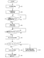
- FIG. 2 is a flowchart illustrating an example of a control flow executed by the control unit 201 of the refrigeration cycle apparatus according to the present embodiment.
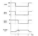
- FIG. 3 shows an example of operation timings of the compressor 21, the solenoid valve 23, and the expansion valve 27 in the refrigeration cycle apparatus according to the present embodiment, and an example of a time change of the pressure in the third section 103 detected by the pressure sensor 61. It is a timing chart.
- the compressor 21 is operating at a predetermined frequency, and the solenoid valve 23 which is an example of the first valve is in an open state.
- the expansion valve 27 which is an example of the second valve is in an open state at a predetermined opening degree.
- the pressure in the third section 103 detected by the pressure sensor 61 during the operation of the refrigeration cycle apparatus is the low-pressure side pressure of the refrigeration cycle circuit 10.
- the compressor 21 stops, the refrigerant on the indoor unit 40 side is collected in the outdoor heat exchanger 24.
- the pressure in the third section 103 detected by the pressure sensor 61 gradually increases as the low-pressure side pressure and the high-pressure side pressure in the refrigeration cycle circuit 10 are equalized.
- control unit 201 When a predetermined time has elapsed since the compressor 21 stopped (step S3 in FIG. 2), the control unit 201 performs control to close the expansion valve 27 (step S4 in FIG. 2 and time t2 in FIG. 3). . Since the electromagnetic valve 23 is already in the closed state, the space in the third section 103 and the space in the fourth section 104 are separated from each other when the expansion valve 27 is closed.
- the control unit 201 acquires the pressure Pb of the third section 103 based on the detection signal from the pressure sensor 61 (time t2 in FIG. 3).
- the pressure Pb is used as one of reference values for determining whether or not refrigerant has leaked during a period in which the compressor 21 is stopped. Therefore, the value of the pressure Pb is stored in the control unit 201 until the operation of the compressor 21 is started next. The actual determination of the presence or absence of refrigerant leakage is performed during the stop period of the compressor 21 after the pressure Pb is obtained.
- the pressure in the third section 103 is detected by the pressure sensor 61 that detects the low-pressure side pressure of the refrigeration cycle circuit 10.
- the pressure Pb may be acquired at time t2 as in the present embodiment, or the compressor 21 operates at time t1, between time t1 and time t2, or before time t1. May be acquired during a certain period.
- the pressure in the third section 103 decreases during the period from when the pressure Pb is obtained to when the compressor 21 is next started, in the following two cases. Almost limited.
- the refrigerant leaks in the third section 103 and the case where the saturated gas pressure at the ambient temperature becomes lower than the pressure Pb due to the decrease in the ambient temperature of the third section 103.
- the pressure in the third section 103 becomes lower than the pressure Pb during a period from when the pressure Pb is obtained to when the compressor 21 is next started, the refrigerant leaks in the third section 103.
- the pressure in the third section 103 may be detected by a pressure sensor that detects the high pressure of the refrigeration cycle circuit 10. In this case, the pressure Pb is obtained after the low pressure side pressure and the high pressure side pressure of the refrigeration cycle circuit 10 are equalized.
- Step S6 the control unit 201 acquires the pressure Pa and the pressure Pc at that time before starting the operation of the refrigeration cycle apparatus.
- the pressure Pa is the pressure in the third section 103 detected by the pressure sensor 61.
- the pressure Pc is a saturated gas pressure at the ambient temperature of the third section 103.
- the ambient temperature of the third section 103 is detected by a temperature sensor 63 provided in the third section 103.
- the temperature sensor that detects the temperature of the third section 103 is provided only in the indoor unit 40, but may be provided in the outdoor unit 30, the extension pipe 51, or the extension pipe 52. Further, as the ambient temperature of the third section 103, an indoor air temperature or an outdoor air temperature may be selected.
- control unit 201 determines whether or not the pressure Pb and the current pressures Pa and Pc satisfy the relationships Pa ⁇ Pb and Pa ⁇ Pc (step S7). If both the relationship of Pa ⁇ Pb and the relationship of Pa ⁇ Pc are satisfied, the process proceeds to step S8. If at least one of the relationship of Pa ⁇ Pb and the relationship of Pa ⁇ Pc is not satisfied, the process proceeds to step S10.
- step S8 the control unit 201 performs a process of informing the notification unit 203 of the leakage of the refrigerant.
- step S9 the control unit 201 performs processing for prohibiting the start of operation of the refrigeration cycle apparatus. Thereby, the compressor 21 is maintained in the stopped state, and the solenoid valve 23 and the expansion valve 27 are maintained in the closed state, so that the third section 103 including the indoor heat exchanger 29 is separated from the fourth section 104. The state continues.
- the amount of the refrigerant leaking into the room can be suppressed to a small amount. Further, since it is possible to prevent the operation of the refrigeration cycle apparatus from being started in a state where the refrigerant leaks in the third section 103, it is possible to prevent an increase in the amount of refrigerant leakage due to the operation of the compressor 21. .
- step S10 the control unit 201 starts the operation of the compressor 21 and does not perform the process of informing the notification unit 203 of the leakage of the refrigerant, and performs the process of opening the solenoid valve 23 and the expansion valve 27. Do. Thereby, the operation of the refrigeration cycle apparatus is started (time t3 in FIG. 3).
- a process of acquiring the pressure Pa and the pressure Pc (Step S6), and a determination process using the acquired pressure Pa and the pressure Pc and the already acquired pressure Pb (Step S7). Is performed only immediately before the start of operation of the refrigeration cycle apparatus upon receipt of the operation start signal. However, the processing of step S6 and step S7 may be periodically performed at predetermined time intervals during the suspension period of the refrigeration cycle device.
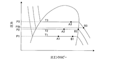
- FIG. 4 is a ph diagram showing the state of the refrigerant in the refrigeration cycle apparatus according to the present embodiment.
- the horizontal axis in FIG. 4 represents the specific enthalpy, and the vertical axis represents the pressure.
- P1 state A1
- the pressure P1 is equal to the saturation pressure of the refrigerant at the ambient temperature T1.
- the pressure of the refrigerant increases from P1 to P2 (state A2). Since the state A2 is a gas-liquid two-phase state, the pressure P2 is equal to the saturation pressure of the refrigerant at the ambient temperature T2. Further, when the ambient temperature of the closed space increases from T2 to T3, the pressure of the refrigerant increases from P2 to P3 (state A3). Since the state A3 is a gas-liquid two-phase state, the pressure P3 is equal to the saturation pressure of the refrigerant at the ambient temperature T3.
- the pressure of the refrigerant changes according to the change in the ambient temperature, and becomes equal to the saturation pressure of the ambient temperature. Therefore, when the pressure of the refrigerant is lower than the saturation pressure of the ambient temperature, it can be determined that the refrigerant is leaking from the closed space. Therefore, as long as the liquid refrigerant is always present in the closed space, it is possible to determine the presence or absence of the refrigerant leakage from the closed space only by comparing the pressure of the refrigerant with the saturation pressure of the ambient temperature.
- the pressure of the refrigerant existing in the closed space at the ambient temperature T1 is P1 as in the state A1, but the state of the refrigerant is a state B1 having a higher degree of dryness than the state A1. Since the state B1 is a gas-liquid two-phase state, the pressure P1 is equal to the saturation pressure of the refrigerant at the ambient temperature T1. When the ambient temperature of the closed space increases from T1 to T2, the pressure of the refrigerant increases from P1 to P2 (state B2). Since the state B2 is a saturated gas state, the pressure P2 is equal to the saturation pressure of the refrigerant at the ambient temperature T2.
- the state of the refrigerant changes to state B3. Since the state B3 is a superheated gas state, the pressure P3b in the state B3 is lower than the saturation pressure P3 of the refrigerant at the ambient temperature T3. As described above, when the liquid refrigerant no longer exists in the closed space, the pressure of the refrigerant becomes lower than the saturation pressure at the ambient temperature. Therefore, considering that the refrigerant in the closed space may become a superheated gas, it is not possible to determine the presence or absence of refrigerant leakage from the closed space only by comparing the pressure of the refrigerant with the saturation pressure of the ambient temperature. .
- FIG. 5 is a conceptual diagram showing an example of a range of pressure Pa in which the refrigerant is determined to leak in the refrigeration cycle apparatus according to the present embodiment.
- the horizontal axis in FIG. 5 represents temperature [° C.], and the vertical axis represents pressure [MPaG].
- the pressure Pb is assumed to be approximately 1.3 MPaG.
- the refrigerant in the third section 103 when the compressor 21 is stopped is in a saturated gas state.
- the saturated gas pressure Pc of the ambient temperature acquired during the stop period of the compressor 21 increases as the ambient temperature increases.
- the saturation gas pressure Pc becomes lower than the pressure Pb.
- a region A indicated by hatching that rises to the right is a range of the pressure Pa that satisfies the relationship of Pa ⁇ Pb and Pa ⁇ Pc.
- a region B indicated by hatching that rises to the left is a range of the pressure Pa that satisfies the relationship of Pa ⁇ Pb and Pa ⁇ Pc.
- the presence / absence of refrigerant leakage is determined based on the comparison between the pressure Pa and the pressure Pb as well as the comparison between the pressure Pa and the saturated gas pressure Pc. Accordingly, when the pressure Pa is within the range of the region A, it is determined that the refrigerant has leaked, and when the pressure Pa is within the range of the region B, it is determined that the refrigerant has not leaked. That is, in the present embodiment, when Pa ⁇ Pb and Pa ⁇ Pc are satisfied during the stop period of the compressor 21, it is determined that the refrigerant has leaked, and the refrigerant leak is notified.
- the air conditioner is stopped for a long time. For example, the air conditioner is stopped in summer, and the presence or absence of refrigerant leakage is determined in autumn when the outside air temperature decreases.
- the pressure Pb obtained before and after the compressor 21 of the air conditioner is stopped is set to 1.23 MPa corresponding to a saturation temperature of 17 ° C.
- the saturated gas pressure at the ambient temperature (for example, the room temperature) when determining whether or not refrigerant has leaked Pc is set to 1.15 MPa corresponding to a saturation temperature of 15 ° C.
- the presence or absence of refrigerant leakage is determined after the air conditioner is stopped for a short period of time.
- the pressure Pb obtained before and after the stop of the compressor 21 of the air conditioner is set to 1.23 MPa corresponding to the saturation temperature of 17 ° C.
- the saturated gas pressure Pc of the ambient temperature when determining the presence or absence of refrigerant leakage is set to the saturation temperature of 25 ° C. 1.56 MPa corresponding to
- the pressure Pa in the third section 103 at the time of determining the presence or absence of refrigerant leakage is less than 1.23 MPa, it is determined that the refrigerant has leaked because the relationship Pa ⁇ Pb and Pa ⁇ Pc is satisfied. Is notified by the notification unit 203 to the effect that the is leaked.
- the refrigeration cycle apparatus includes compressor 21, outdoor heat exchanger 24 functioning as an evaporator, and indoor heat exchanger 29 functioning as a condenser, and circulates refrigerant.
- a section between the outdoor heat exchanger 24 and the indoor heat exchanger 29 passing through the compressor 21 in the refrigeration cycle circuit 10 and the compressor 21 in the refrigeration cycle circuit 10 is defined as a first section 101.
- a section between the outdoor heat exchanger 24 and the indoor heat exchanger 29 that does not pass through 21 is defined as a second section 102, the solenoid valve 23 provided in the first section 101 and the second section 102 are provided.
- a section between the expansion valve 27 and the solenoid valve 23 and the expansion valve 27 passing through the indoor heat exchanger 29 in the refrigeration cycle circuit 10 is defined as a third section 103
- the section is provided in the third section 103.
- the control unit 201 is configured to close the solenoid valve 23 at a time t1 when the compressor 21 is stopped, and to close the expansion valve 27 at a time t2 after the time t1.
- the control unit 201 is configured to acquire the pressure Pb of the third section 103 during the operation of the compressor 21 at the time t1, from the time t1 to the time t2, at the time t2, or before the time t1. Have been.
- the control unit 201 determines that the pressure Pb and the pressure Pa of the third section 103 and the saturated gas pressure Pc of the ambient temperature detected during the period in which the compressor 21 is stopped satisfy Pa ⁇ Pb and Pa ⁇ Pc, respectively.
- the notification unit 203 is configured to notify the leakage of the refrigerant.
- the solenoid valve 23 is an example of a first valve.
- the expansion valve 27 is an example of a second valve.
- Time t1 is an example of a first timing.
- Time t2 is an example of a second timing.
- the pressure Pa in the third section 103 during the stop period of the compressor 21 is not only compared with the saturated gas pressure Pc, but also in the third section 103 detected before and after the compressor 21 stops. It is also compared with the pressure Pb.
- the pressure Pa becomes lower than the saturation gas pressure Pc and the pressure Pa becomes lower than the pressure Pb the leakage of the refrigerant is reported. Therefore, not only when the refrigerant in the third section 103 is in a two-phase state, but also when the refrigerant in the third section 103 is in a superheated gas state, the leakage of the refrigerant can be detected more accurately.
- erroneous detection and notification of refrigerant leakage can be reduced, the reliability of notification of refrigerant leakage can be improved.
- control unit 201 when pressure Pa, pressure Pb, and saturated gas pressure Pc satisfy the relationship of Pa ⁇ Pb and Pa ⁇ Pc, control unit 201 reports a refrigerant leak. It is configured not to notify 203. According to this configuration, erroneous detection and notification of refrigerant leakage can be reduced.
- control unit 201 is configured to acquire pressure Pb at time t2. At time t1, from time t1 to time t2, at time t2, and during operation of the compressor 21, the highest pressure in the third section 103 is at time t2 (see FIG. 3). Therefore, when the pressure Pb is obtained at the time t2, the pressure Pb, which is one of the thresholds of the pressure Pa, is set to a higher value, that is, a value close to the pressure Pa. Accordingly, when the pressure Pa decreases due to the leakage of the refrigerant, the leakage of the refrigerant can be detected even if the decrease width of the pressure Pa is small. Therefore, according to the above configuration, it is possible to accurately or early detect leakage of the refrigerant.
- control unit 201 determines whether or not pressure Pa, pressure Pb, and saturated gas pressure Pc satisfy the relationship of Pa ⁇ Pb and Pa ⁇ Pc, at least by determining whether or not compression is performed.
- the operation is performed before the operation of the machine 21 is started. According to this configuration, when the refrigerant is leaking, the operation of the compressor 21 can be prevented from being started, so that an increase in the amount of refrigerant leakage due to the start of the operation of the compressor 21 is prevented. be able to.
- each of the first valve and the second valve may be any one of a solenoid valve, an electric valve, and an electronic expansion valve.
- the refrigeration cycle apparatus includes a compressor 21, an outdoor heat exchanger 24 functioning as an evaporator, and an indoor heat exchanger 29 functioning as a condenser, and circulates a refrigerant. 10 and a section between the outdoor heat exchanger 24 and the indoor heat exchanger 29 passing through the compressor 21 in the refrigeration cycle circuit 10 is defined as a first section 101, and does not pass through the compressor 21 in the refrigeration cycle circuit 10.
- the solenoid valve 23 provided in the first section 101 and the expansion valve 27 provided in the second section 102
- a pressure sensor provided in the third section 103 is provided.
- a temperature sensor 63 for detecting the ambient temperature of the third section 103, a control unit 201, a.
- the control unit 201 is configured to close the solenoid valve 23 at a time t1 when the compressor 21 is stopped, and to close the expansion valve 27 at a time t2 after the time t1.
- the pressure Pb in the third section 103 is acquired during the operation of the compressor 21 at the time t1, from the time t1 to the time t2, at the time t2, or before the time t1.
- the control unit 201 determines that the pressure Pb and the pressure Pa of the third section 103 and the saturated gas pressure Pc of the ambient temperature detected during the period in which the compressor 21 is stopped satisfy Pa ⁇ Pb and Pa ⁇ Pc, respectively. When the relationship is satisfied, it is configured to determine that the refrigerant has leaked.
- the solenoid valve 23 is an example of a first valve.
- the expansion valve 27 is an example of a second valve.
- Time t1 is an example of a first timing.
- Time t2 is an example of a second timing.
- the pressure Pa in the third section 103 during the stop period of the compressor 21 is not only compared with the saturated gas pressure Pc, but also in the third section 103 detected before and after the compressor 21 stops. It is also compared with the pressure Pb.
- the pressure Pa becomes lower than the saturated gas pressure Pc and the pressure Pa becomes lower than the pressure Pb it is determined that the refrigerant has leaked. Therefore, not only when the refrigerant in the third section 103 is in a two-phase state, but also when the refrigerant in the third section 103 is in a superheated gas state, the leakage of the refrigerant can be detected more accurately.
- controller 201 when pressure Pa, pressure Pb, and saturated gas pressure Pc satisfy the relationship of Pa ⁇ Pb and Pa ⁇ Pc, controller 201 does not leak refrigerant. Is determined. According to this configuration, erroneous detection and notification of refrigerant leakage can be reduced.
- Embodiment 2 FIG. A refrigeration cycle apparatus according to Embodiment 2 of the present invention will be described.
- a non-azeotropic mixed refrigerant is used as the refrigerant circulating in the refrigeration cycle circuit 10.
- FIG. 6 is a ph diagram showing the state of the refrigerant in the refrigeration cycle apparatus according to the present embodiment.
- the saturated gas pressure P1G at the ambient temperature T1 is lower than the saturated liquid pressure P1L at the same ambient temperature T1.
- the saturated gas pressure P2G at the ambient temperature T2 becomes lower than the saturated liquid pressure P2L at the same ambient temperature T2
- the saturated gas pressure P3G at the ambient temperature T3 becomes the saturated liquid pressure P3L at the same ambient temperature T3. Lower than.
- the saturated gas pressure is lower.
- the saturated gas pressure at the ambient temperature of the third section 103 is used as the pressure Pc when judging the presence or absence of refrigerant leakage.
- the present invention is not limited to the above embodiment, and various modifications are possible.
- a refrigeration cycle device that can be executed by switching between the heating operation and the cooling operation has been described as an example, but the present invention is also applicable to a refrigeration cycle device that can execute only the heating operation.
- an air conditioner is described as an example of a refrigeration cycle device.
- the present invention can be applied to other refrigeration cycle devices that can perform a heating operation such as a hot water supply device.
- the refrigeration cycle apparatus including one outdoor unit 30 and one indoor unit 40 has been described as an example.
- the refrigeration cycle apparatus includes a plurality of outdoor units 30.
- a plurality of indoor units 40 may be provided.
Landscapes
- Engineering & Computer Science (AREA)
- Physics & Mathematics (AREA)
- Mechanical Engineering (AREA)
- Thermal Sciences (AREA)
- General Engineering & Computer Science (AREA)
- Air Conditioning Control Device (AREA)
- Separation By Low-Temperature Treatments (AREA)
- Compression-Type Refrigeration Machines With Reversible Cycles (AREA)
Abstract
Dispositif à cycle frigorifique qui comprend : une première soupape disposée dans une première section; une seconde soupape disposée dans une seconde section; un capteur de pression disposé dans une troisième section qui se trouve entre la première soupape et la seconde soupape et passe à travers un échangeur de chaleur interne; un capteur de température qui détecte la température autour de la troisième section; et une unité de commande. L'unité de commande ferme la première soupape à un premier instant lorsqu'un compresseur est arrêté, ferme la seconde soupape à un second instant, acquiert la pression Pb de la troisième section au premier instant, dans la période entre le premier instant et le second instant, au second instant, ou pendant le fonctionnement du compresseur, et notifie une unité de notification d'une fuite de fluide frigorigène lorsque la pression Pb, la pression Pa dans la troisième section et la pression de gaz de saturation Pc à la température ambiante satisfont aux conditions suivantes: Pa<Pb et Pa<Pc.
Priority Applications (4)
| Application Number | Priority Date | Filing Date | Title |
|---|---|---|---|
| EP18925175.4A EP3819564B1 (fr) | 2018-07-06 | 2018-07-06 | Dispositif à cycle frigorifique |
| JP2020528653A JP6861897B2 (ja) | 2018-07-06 | 2018-07-06 | 冷凍サイクル装置 |
| ES18925175T ES2943107T3 (es) | 2018-07-06 | 2018-07-06 | Dispositivo de ciclo de refrigeración |
| PCT/JP2018/025709 WO2020008625A1 (fr) | 2018-07-06 | 2018-07-06 | Dispositif à cycle frigorifique |
Applications Claiming Priority (1)
| Application Number | Priority Date | Filing Date | Title |
|---|---|---|---|
| PCT/JP2018/025709 WO2020008625A1 (fr) | 2018-07-06 | 2018-07-06 | Dispositif à cycle frigorifique |
Publications (1)
| Publication Number | Publication Date |
|---|---|
| WO2020008625A1 true WO2020008625A1 (fr) | 2020-01-09 |
Family
ID=69059409
Family Applications (1)
| Application Number | Title | Priority Date | Filing Date |
|---|---|---|---|
| PCT/JP2018/025709 Ceased WO2020008625A1 (fr) | 2018-07-06 | 2018-07-06 | Dispositif à cycle frigorifique |
Country Status (4)
| Country | Link |
|---|---|
| EP (1) | EP3819564B1 (fr) |
| JP (1) | JP6861897B2 (fr) |
| ES (1) | ES2943107T3 (fr) |
| WO (1) | WO2020008625A1 (fr) |
Cited By (4)
| Publication number | Priority date | Publication date | Assignee | Title |
|---|---|---|---|---|
| CN113432212A (zh) * | 2021-06-30 | 2021-09-24 | 海信(广东)空调有限公司 | 控制除湿机的方法、除湿机和计算机可读存储介质 |
| CN114963522A (zh) * | 2021-06-29 | 2022-08-30 | 青岛海尔新能源电器有限公司 | 热水器的控制方法、装置及热水器 |
| WO2022244798A1 (fr) * | 2021-05-21 | 2022-11-24 | ダイキン工業株式会社 | Système de gestion de fuite de fluide frigorigène |
| WO2023084779A1 (fr) * | 2021-11-15 | 2023-05-19 | 三菱電機株式会社 | Climatiseur |
Families Citing this family (3)
| Publication number | Priority date | Publication date | Assignee | Title |
|---|---|---|---|---|
| WO2020008624A1 (fr) * | 2018-07-06 | 2020-01-09 | 三菱電機株式会社 | Dispositif à cycle frigorifique |
| US20230080672A1 (en) * | 2021-09-16 | 2023-03-16 | Trane International Inc. | Refrigerant leak mitigation system |
| FR3136548B1 (fr) * | 2022-06-09 | 2024-08-23 | Alsacienne De Maintenance Frigorifique | Dispositif mesurant la quantité de réfrigérant contenue dans les circuits frigorifiques pour en déterminer l’étanchéité |
Citations (3)
| Publication number | Priority date | Publication date | Assignee | Title |
|---|---|---|---|---|
| JP2004245457A (ja) * | 2003-02-12 | 2004-09-02 | Japan Climate Systems Corp | 車両用空調装置 |
| JP2005241050A (ja) | 2004-02-24 | 2005-09-08 | Mitsubishi Electric Building Techno Service Co Ltd | 空調システム |
| JP2015206509A (ja) * | 2014-04-18 | 2015-11-19 | 日立アプライアンス株式会社 | 冷温熱機器 |
-
2018
- 2018-07-06 ES ES18925175T patent/ES2943107T3/es active Active
- 2018-07-06 JP JP2020528653A patent/JP6861897B2/ja not_active Expired - Fee Related
- 2018-07-06 EP EP18925175.4A patent/EP3819564B1/fr active Active
- 2018-07-06 WO PCT/JP2018/025709 patent/WO2020008625A1/fr not_active Ceased
Patent Citations (3)
| Publication number | Priority date | Publication date | Assignee | Title |
|---|---|---|---|---|
| JP2004245457A (ja) * | 2003-02-12 | 2004-09-02 | Japan Climate Systems Corp | 車両用空調装置 |
| JP2005241050A (ja) | 2004-02-24 | 2005-09-08 | Mitsubishi Electric Building Techno Service Co Ltd | 空調システム |
| JP2015206509A (ja) * | 2014-04-18 | 2015-11-19 | 日立アプライアンス株式会社 | 冷温熱機器 |
Non-Patent Citations (1)
| Title |
|---|
| See also references of EP3819564A4 |
Cited By (7)
| Publication number | Priority date | Publication date | Assignee | Title |
|---|---|---|---|---|
| WO2022244798A1 (fr) * | 2021-05-21 | 2022-11-24 | ダイキン工業株式会社 | Système de gestion de fuite de fluide frigorigène |
| JP2022179217A (ja) * | 2021-05-21 | 2022-12-02 | ダイキン工業株式会社 | 冷媒漏洩管理システム |
| JP2024015433A (ja) * | 2021-05-21 | 2024-02-01 | ダイキン工業株式会社 | 冷媒漏洩管理システム |
| CN114963522A (zh) * | 2021-06-29 | 2022-08-30 | 青岛海尔新能源电器有限公司 | 热水器的控制方法、装置及热水器 |
| CN114963522B (zh) * | 2021-06-29 | 2023-08-18 | 青岛海尔新能源电器有限公司 | 热水器的控制方法、装置及热水器 |
| CN113432212A (zh) * | 2021-06-30 | 2021-09-24 | 海信(广东)空调有限公司 | 控制除湿机的方法、除湿机和计算机可读存储介质 |
| WO2023084779A1 (fr) * | 2021-11-15 | 2023-05-19 | 三菱電機株式会社 | Climatiseur |
Also Published As
| Publication number | Publication date |
|---|---|
| EP3819564A4 (fr) | 2021-06-23 |
| ES2943107T3 (es) | 2023-06-09 |
| EP3819564A1 (fr) | 2021-05-12 |
| JP6861897B2 (ja) | 2021-04-21 |
| EP3819564B1 (fr) | 2023-03-29 |
| JPWO2020008625A1 (ja) | 2020-12-17 |
Similar Documents
| Publication | Publication Date | Title |
|---|---|---|
| WO2020008625A1 (fr) | Dispositif à cycle frigorifique | |
| JP6798322B2 (ja) | 遮断弁を有する冷凍装置 | |
| US11181303B2 (en) | Air-conditioning apparatus and air-conditioning system | |
| JP6861804B2 (ja) | 空気調和機 | |
| EP2354724B1 (fr) | Climatiseur d'air et son procédé de commande | |
| CN100587350C (zh) | 一种空调器故障检测方法及系统 | |
| JP2017142039A (ja) | 空気調和装置 | |
| EP2728280A1 (fr) | Climatiseur et son procédé de fonctionnement | |
| JP6628833B2 (ja) | 冷凍サイクル装置 | |
| JP2017142038A (ja) | 冷凍サイクル装置 | |
| JP7621515B2 (ja) | 空気調和装置 | |
| JP2019002639A (ja) | 空気調和機の冷媒漏洩検知方法、および、空気調和機 | |
| US11340001B2 (en) | Refrigeration cycle apparatus | |
| AU2017408715A1 (en) | Outdoor unit of air-conditioning apparatus | |
| AU2013275605B2 (en) | Refrigerating Device | |
| EP4317836A1 (fr) | Climatiseur | |
| WO2016129027A1 (fr) | Dispositif de conditionnement d'air | |
| KR101769821B1 (ko) | 공기조화기 및 그 제어방법 | |
| JP7112051B2 (ja) | 冷凍サイクル装置 | |
| WO2023002520A1 (fr) | Dispositif à cycle frigorifique et dispositif de climatisation | |
| JP2017067397A (ja) | 冷凍装置 | |
| JP2023173581A (ja) | 空調システム |
Legal Events
| Date | Code | Title | Description |
|---|---|---|---|
| 121 | Ep: the epo has been informed by wipo that ep was designated in this application |
Ref document number: 18925175 Country of ref document: EP Kind code of ref document: A1 |
|
| ENP | Entry into the national phase |
Ref document number: 2020528653 Country of ref document: JP Kind code of ref document: A |
|
| NENP | Non-entry into the national phase |
Ref country code: DE |