WO2020008655A1 - Dispositif pour générer une fonction de transfert associée à la tête, procédé pour générer une fonction de transfert associée à la tête, et programme - Google Patents
Dispositif pour générer une fonction de transfert associée à la tête, procédé pour générer une fonction de transfert associée à la tête, et programme Download PDFInfo
- Publication number
- WO2020008655A1 WO2020008655A1 PCT/JP2018/029903 JP2018029903W WO2020008655A1 WO 2020008655 A1 WO2020008655 A1 WO 2020008655A1 JP 2018029903 W JP2018029903 W JP 2018029903W WO 2020008655 A1 WO2020008655 A1 WO 2020008655A1
- Authority
- WO
- WIPO (PCT)
- Prior art keywords
- head
- transfer function
- related transfer
- amplitude value
- listener
- Prior art date
- Legal status (The legal status is an assumption and is not a legal conclusion. Google has not performed a legal analysis and makes no representation as to the accuracy of the status listed.)
- Ceased
Links
Images


Classifications
-
- G—PHYSICS
- G10—MUSICAL INSTRUMENTS; ACOUSTICS
- G10K—SOUND-PRODUCING DEVICES; METHODS OR DEVICES FOR PROTECTING AGAINST, OR FOR DAMPING, NOISE OR OTHER ACOUSTIC WAVES IN GENERAL; ACOUSTICS NOT OTHERWISE PROVIDED FOR
- G10K15/00—Acoustics not otherwise provided for
Definitions
- the present invention relates to a head-related transfer function generation device, a head-related transfer function generation method, and a program.
- a head-related transfer function generation device a head-related transfer function generation method, and a program.
- a head-related transfer function selection device that selects a head-related transfer function that is similar to its own head-related transfer function is known (for example, see Patent Document 1).
- a measurement unit is configured to perform measurement based on a sound signal picked up by a microphone mounted on a listener's ear. Obtain the listener's head impulse response.
- the feature value extraction unit extracts a feature value of a frequency characteristic corresponding to the head impulse response.
- the characteristic selection unit selects one of the heads from a database in which the head-related transfer functions of the plurality of persons are associated with the feature amounts of the head-related transfer functions. Select the partial transfer function.
- An object of the present invention is to provide a head-related transfer function generation device, a head-related transfer function generation method, and a program that can easily obtain a function.
- the present inventors obtained by performing multiple regression analysis using the pinna shape as an explanatory variable and the amplitude value of the head-related transfer function or initial head-related transfer function as the objective variable at each frequency in each direction.
- the amplitude value of the head-related transfer function of each frequency in each direction is calculated, and the head-related transfer function of the listener itself is calculated. It has been found that it is possible to generate a head-related transfer function that is as accurate as the actually-measured head-related transfer function of the listener without actually performing the measurement.
- One aspect of the present invention is an auricle shape acquisition unit that acquires an auricle shape of a listener, the auricle shape acquired by the auricle shape acquisition unit, and the auricle shape at each frequency in each direction.
- Multiple regression coefficient data that is obtained by converting multiple regression coefficients obtained by performing multiple regression analysis using the head-related transfer function or the amplitude value of the initial head-related transfer function as the objective variable, or
- a head that calculates the amplitude value of the head-related transfer function of each frequency in each direction based on the correspondence between the pinna shape after learning using the teacher data and the amplitude value of the head-related transfer function
- a head-related transfer function generation device including a transfer function amplitude value generation unit.
- the head-related transfer function generation device further includes a multiple regression coefficient data acquisition unit that acquires the stored multiple regression coefficient data, wherein the head-related transfer function amplitude value generation unit includes the pinna Based on the pinna shape acquired by the shape acquisition unit and the multiple regression coefficient data acquired by the multiple regression coefficient data acquisition unit, calculate the amplitude value of the head-related transfer function of each frequency in each direction. You may.
- the head-related transfer function generation device includes a head-related impulse by performing an inverse Fourier transform on the amplitude value of the head-related transfer function of each frequency in each direction generated by the head-related transfer function amplitude value generation unit.
- a head impulse response generator for calculating a response may be further provided.
- the apparatus for generating a head related transfer function may further include a multiple regression coefficient database storing the multiple regression coefficient data.
- the head-related transfer function generation device may further include a multiple regression coefficient data generation unit that generates the multiple regression coefficient data.
- the head-related transfer function generation device may further include a binaural time difference adding unit that adds the impulse response.
- a head-related transfer function generation apparatus includes a teacher data acquisition unit that acquires the teacher data, and the teacher data acquired by the teacher data acquisition unit.
- a learning unit that learns a correspondence relationship between the amplitude value of the function and the teacher data, wherein the teacher data includes an auricle shape of a predetermined listener and an amplitude value of a head-related transfer function of the predetermined listener.
- the head-related transfer function amplitude value generation unit based on the pinna shape acquired by the pinna shape acquisition unit and the correspondence after learning by the learning unit, in each direction The amplitude value of the head-related transfer function at each frequency may be calculated.
- One aspect of the present invention is an auricle shape acquisition step of acquiring an auricle shape of a listener, the auricle shape acquired in the auricle shape acquisition step, and the auricle shape at each frequency in each direction.
- Multiple regression coefficient data that is obtained by converting multiple regression coefficients obtained by performing multiple regression analysis using the head-related transfer function or the amplitude value of the initial head-related transfer function as the objective variable, or
- a head that calculates the amplitude value of the head-related transfer function of each frequency in each direction based on the correspondence between the pinna shape after learning using the teacher data and the amplitude value of the head-related transfer function
- a head-related transfer function generation method comprising a transfer function amplitude value generation step.
- One embodiment of the present invention provides a computer with an auricle shape acquisition step of acquiring an auricle shape of a listener, the auricle shape acquired in the auricle shape acquisition step, and at each frequency in each direction, Multiple regression coefficient data obtained by performing multiple regression analysis using the pinna shape as an explanatory variable and performing multiple regression analysis using the head-related transfer function or the initial head-related transfer function amplitude as the target variable Or, based on the correspondence between the pinna shape and the amplitude value of the head-related transfer function after learning using the teacher data is performed, the amplitude value of the head-related transfer function of each frequency in each direction is calculated. And a head-related transfer function amplitude value generating step.
- a head-related transfer function generating apparatus, a head-related transfer function generating method, and a program can be provided.
- FIG. 1 It is a figure for explaining an ear axis coordinate system. It is a figure which shows the amplitude characteristic of the head-related transfer function measured from the front to the back in the median plane of the upper hemisphere at intervals of 30 [deg.]. It is a figure which shows the amplitude characteristic of the head-related transfer function in the right ear (solid line), the amplitude characteristic of the head-related transfer function in the left ear (dotted line), etc. with respect to the sound source whose rising angle ⁇ in the median plane is 0 [°]. . It is a figure for explaining individual difference of a head-related transfer function. It is a figure showing an example of the outline of the head transfer function generating device of a 1st embodiment. FIG.
- FIG. 3 is a front view of the left ear for explaining the pinna shapes x 1 to x 8 and x 10 to x 13 of the listener. It is a sectional view seen from the lower side of Fig. 5A the left ear in order to explain the pinna shape x 9 of the listener.
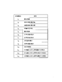
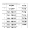
- FIG. 9 is a diagram showing names of measurement sites corresponding to the pinna shapes x 1 to x 13 of the listener. It is a figure for explaining other examples of a pinna shape of a listener acquired by a pinna shape acquisition part of a head-related transfer function generation device of a 1st embodiment.
- FIG. 7A It is a front view of the left ear for demonstrating a listener's pinna shape (each part of a listener's pinna). It is a sectional view seen from the lower side in FIG. 7A to the left ear in order to explain the pinna shape (the measurement site) x 14 of the listener.
- Listener auricle shape definition of (measurement portion) x 1 ⁇ x 14 is a diagram for explaining the like. It is a figure which shows the amplitude value of the head-related transfer function which the head-related transfer function amplitude value generation part produced
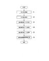
- FIG. 5 is a flowchart illustrating an example of a process performed when the head-related transfer function generation device of the first embodiment generates an amplitude value of a head-related transfer function.
- the head generated using multiple regression coefficient data obtained by performing multiple regression analysis using the pinna shapes x 1 to x 13 as explanatory variables and the amplitude value of the (all sections) head-related transfer function as an objective variable. It is a figure showing the amplitude value of a partial transfer function. Head transfer function generated using multiple regression coefficient data obtained by performing multiple regression analysis using the pinna shapes x 1 to x 13 as explanatory variables and the amplitude value of the initial head transfer function as the objective variable
- FIG. 6 is a diagram showing amplitude values of the.
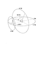
- FIG. 1 is a diagram for explaining the ear axis coordinate system.
- the ear axis coordinate system shown in FIG. 1 is defined as follows.
- the origin is the midpoint of a line connecting the left and right ear canal entrances of the listener.
- the horizontal plane is a plane connecting the right orbital point and the left and right tragus.
- the cross section (not shown) is a plane passing through the left and right ear canal entrances and orthogonal to the horizontal plane.
- the median plane is a plane orthogonal to both the horizontal plane and the transverse section (a plane that bisects the listener to the left and right).
- the sound source direction is represented by a lateral angle ⁇ and a rising angle ⁇ .
- the lateral angle ⁇ is the complementary angle of an angle formed by a straight line connecting the sound source (the portion indicated by a black circle “ ⁇ ” in FIG. 1) and the origin with the ear axis (a straight line passing through the left and right external auditory canal entrances).
- the rising angle ⁇ is an elevation angle in a sagittal plane passing through the sound source.
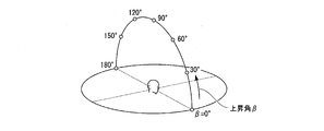
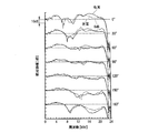
- FIG. 2A is a diagram showing the amplitude characteristics of the head-related transfer functions measured from the front to the rear in the median plane of the upper hemisphere at intervals of 30 °.
- FIG. 2A shows a sound source whose rise angle ⁇ in the median plane is 0 [°], a sound source whose rise angle ⁇ in the median plane is 30 [°], and a rise angle ⁇ in the median plane of 60 [°].
- ° a sound source with a rise angle ⁇ in the median plane of 90 °
- a sound source with a rise angle ⁇ in the median plane of 120 ° and a rise angle ⁇ in the median plane of 150 °.
- FIG. 2B shows the amplitude characteristic of the head-related transfer function at the right ear (solid line) and the amplitude characteristic of the head-related transfer function at the left ear (dotted line) for a sound source having an elevation angle ⁇ of 0 [°] in the median plane.
- FIG. 2B shows the amplitude characteristics of the head-related transfer function at the right ear (solid line) and the amplitude characteristics of the head-related transfer function at the left ear (solid line) for a sound source whose elevation angle ⁇ in the median plane is 0 [°].
- the amplitude characteristic of the head-related transfer function at the right ear (solid line) and the amplitude characteristic of the head-related transfer function at the left ear (dotted line) for a sound source with a rising angle ⁇ of 30 [°] in the median plane The amplitude characteristic of the head-related transfer function at the right ear (solid line) and the amplitude characteristic of the head-related transfer function at the left ear (dotted line) for a sound source having a rising angle ⁇ of 60 [°] in the median plane
- the amplitude characteristic of the head-related transfer function at the right ear (solid line) and the amplitude characteristic of the head-related transfer function at the left ear (dotted line) for a sound source with a rising angle ⁇ of 90 [°] and the rising angle ⁇ in the median plane are The amplitude characteristic of the head-related transfer function at the right ear (solid line) and the amplitude characteristic of the head-related transfer function at the left ear (dotted line) for a sound source of
- the vertical axis in FIG. 2B indicates the relative amplitude [dB], and the horizontal axis in FIG. 2B indicates the frequency [kHz].
- the head-related transfer function differs depending on the incident direction of the sound wave. This is because the head shape and the pinna shape of the listener are asymmetrical in any of the front, rear, left, right, up, and down directions. The listener perceives the direction of the sound using the incident direction dependency as a clue.
- the listener perceives a sound image in that direction. That is, for example, when reproducing the amplitude characteristic (solid line) of the head-related transfer function at the right ear for the sound source whose rising angle ⁇ in the median plane shown in FIG. 2B is 0 [°], it has the amplitude characteristic of the head-related transfer function.
- the listener perceives the sound image in the direction in which the elevation angle ⁇ in the median plane is 0 [°].
- the sound waves emitted from the sound source reach the eardrum of the listener, the listener has various perceptions. The whole of what the listener perceives with sound waves is called a sound image.
- a sound source is a physical entity, while a sound image is a psychological entity caused by a perceptual phenomenon.
- a sound image has a temporal property (such as a feeling of reverberation, a sense of rhythm, and a sense of persistence), a spatial property (such as a sense of direction, a sense of distance, and a sense of spaciousness) and a qualitative property (such as a size, a height, and a tone).
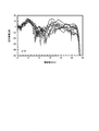
- FIG. 3 is a diagram for explaining individual differences in head-related transfer functions. More specifically, FIG. 3 shows the amplitude characteristics of the head-related transfer function for a sound source in the direction of 0 [°] in the median plane of 10 Japanese people. The vertical axis in FIG. 3 indicates the relative amplitude [dB], and the horizontal axis in FIG.
- the inventor's earnest research has confirmed that when a head-related transfer function of another person is reproduced, an erroneous determination in the front-back and up-down directions (an erroneous determination in the median plane) by the listener occurs.
- the front / back misjudgment is a phenomenon in which the front and rear of the target sound source direction and the perceived sound image direction are reversed.
- the inventor's earnest research has confirmed that when a head-related transfer function of another person is reproduced, a localization in the listener (a phenomenon in which the listener perceives a sound image in the head) occurs. I have.
- Convention three-dimensional sound systems and sound VR systems are effective only for specific listeners, and The biggest reason for the lack of widespread use is that individual differences in head related transfer functions have not been overcome.
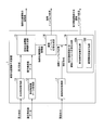
- FIG. 4 is a diagram illustrating an example of an outline of the head-related transfer function generation device 1 according to the first embodiment.
- the head-related transfer function generation device 1 includes an auricle shape acquisition unit 11, a multiple regression coefficient data acquisition unit 12, and a head-related transfer function amplitude value generation unit 13.
- the pinna shape acquisition unit 11 acquires the pinna shapes x 1 to x 13 (see FIGS. 5A to 5C) of the listener.
- FIGS. 5A to 5C show the shape of the pinna of the listener (measured value of each measurement site of the pinna of the listener) obtained by the pinna shape obtaining unit 11 of the head-related transfer function generation device 1 of the first embodiment. It is a figure for explaining an example.
- FIG. 5A is a front view of the left ear for describing the pinna shapes x 1 to x 8 and x 10 to x 13 of the listener.
- 5B is a sectional view viewed left ear from the lower side of FIG. 5A to explain the pinna shape x 9 of listener.
- FIG. 5C is a diagram showing names of measurement sites corresponding to the pinna shapes x 1 to x 13 of the listener.
- pinna shapes x 1 of the listener is a measure of the maximum ear width of the listener.
- Pinna shape x 2 of the listener is the measurement of the maximum width of the cavity of the concha of the listener.
- Pinna shape x 3 of the listener is the measurement of the maximum width of the listener's tragus and chopped marks.
- Pinna shape x 4 of the listener is the measurement of the maximum width of the helix of the listener.
- Pinna shape x 5 of the listener is the measured value of the maximum ear length of the listener.
- Pinna shape x 6 of the listener is the measurement of the length of the cavity of the concha of the listener.
- Pinna shape x 7 of the listener is the measurement of the length of a cavum Kaifune of the listener.
- Pinna shape x 8 of the listener is the height of the measurement values of the navicular fossa of the listener.
- the listener's pinna shape x 9 (see FIG. 5B) is a measurement of the depth of the concha of the listener.
- Pinna shape x 10 of the listener is the measured value of the slope of the via ear of the listener.
- Pinna shape x 11 of the listener is the length of the measurement values from the ear canal entrance of the listener to the triangular fossa.
- Pinna shape x 12 of the listener is the length of the measurement values from the ear canal entrance of the listener to the cavum Kaifune.
- Pinna shape x 13 of the listener is the length of the measurement values from the ear canal entrance of the listener to the cavum conchae.
- the pinna shapes x 1 to x 13 (see FIGS. 5A to 5C) of the listener acquired by the pinna shape acquisition unit 11 are measured from the pinna of the listener using calipers or the like. It was done.
- the ear type of the listener is first collected, and then the pinna shapes x 1 to x 13 of the listener are measured from the ear type of the listener using calipers or the like.
- the pinna shapes x 1 to x 13 of the listener are acquired by the pinna shape acquisition unit 11.
- an image of the listener's pinna is first captured, and then the listener's pinna shapes x 1 to x 13 are measured using the image. Next, the pinna shapes x 1 to x 13 of the listener are acquired by the pinna shape acquisition unit 11.
- FIG. 6 is another example of the auricle shape of the listener (measured value of each measurement site of the auricle of the listener) acquired by the auricle shape acquisition unit 11 of the head-related transfer function generation device 1 of the first embodiment.
- FIG. Listener pinna shape x 1 ⁇ x 8, x 10 in in FIG. 6 is similar to the pinna shape x 1 ⁇ x 8, x 10 of the listener in FIGS. 5A ⁇ FIG 5C.
- the pinna shape obtaining section 11, ear shape x 1 ⁇ x 13 of a listener as shown in FIGS. 5A ⁇ FIG. 5C is obtained.
- the pinna shape acquisition unit 11 uses the pinna shapes x 1 to x 8 and x 10 of the listener shown in FIG. 6 and the pinna shape x of the listener shown in FIG. 5B. 9 is obtained.
- the head-related transfer function generating apparatus 1 is configured to acquire the listener's pinna shape x 1 to x 8 and x 10 shown in FIG. 6 and the listener's pinna shape x 9 shown in FIG. 5B.
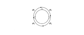
- FIGS. 7A to 7C show the shape of the listener's pinna (measured values of each measurement site of the listener's pinna) acquired by the pinna shape acquisition unit 11 of the head-related transfer function generation device 1 of the first embodiment. It is a figure for explaining another example. Specifically, FIG. 7A is a front view of the left ear for explaining the shape of the pinna of the listener (each part of the pinna of the listener). Figure 7B is a cross-sectional view of the left ear from the lower side of FIG. 7A to explain the pinna shape (the measurement site) x 14 of the listener. FIG. 7C is a diagram for explaining the definitions of the auricle shapes (measurement sites) x 1 to x 14 of the listener.
- portions C 1 is the inner boundary of the helix.
- Site C 2 are paired wheels.
- Site C 3 is outside the boundary line of the concha.
- Site p 0 is the origin (the ear canal entrance).
- Site p 1 is a straight line and the intersection of site C 1 rising angle 120 °.
- Site p 2 is a straight line and the intersection of site C 1 rising angle 150 °.
- Site p 3 is linear and the intersection portion C 1 of the rising angle 180 °.
- Sites p 4 is the intersection of the straight line and part C 2 rising angle 120 °.
- Site p 5 is the intersection of the straight line and part C 2 rising angle 150 °.
- Site p 6 is the intersection of the straight line and part C 2 rising angle 180 °.
- Site p 7 is the intersection of the straight line and part C 3 of the rising angle 120 °.
- Site p 8 is the intersection of the straight line and part C 3 of the rising angle 150 °.
- Site p 9 is the intersection of the straight line and part C 3 of the rising angle 180 °.
- Site p 10 is the intersection of the straight line and part C 3 of the rising angle 210 °.
- Site p 11 is the intersection of the straight line and part C 3 of the rising angle 240 °.
- Site p 12 is the intersection of the straight line and part C 3 of the rising angle 270 °.
- Listener pinna shape (measurement portion) x 1 is the length of the portion p 1 from the site p 0.
- Listener pinna shape (measurement portion) x 2 is the length of the portion p 2 from the site p 0.
- Listener pinna shape (the measurement site) x 3 is the length of the portion p 3 from the site p 0.
- Listener pinna shape (the measurement site) x 4 is the length of the portion p 4 from the site p 0.
- Listener pinna shape (the measurement site) x 5 is the length of the portion p 5 from the site p 0.
- Listener pinna shape (measurement portion) x 6 is the length of the portion p 6 from the site p 0.
- Pinna shape (the measurement site) x 7 of the listener is the length of the portion p 7 from the site p 0.
- Pinna shape (the measurement site) x 8 of the listener is the length of the portion p 8 from the site p 0.
- Listener pinna shape (the measurement site) x 9 is the length of the portion p 9 from the site p 0.
- Pinna shape (the measurement site) x 10 of the listener is the length of the portion p 10 from site p 0.
- Pinna shape (the measurement site) x 11 of the listener is the length of the portion p 11 from site p 0.
- Listener pinna shape (the measurement site) x 12 is the length of the portion p 12 from site p 0.
- Pinna shape x 13 of the listener is the measured value of the slope of the via ear of the listener.
- the listener's pinna shape x 14 is a measurement of the depth of the concha of the listener.
- the pinna shape acquiring unit 11 acquires the pinna shapes x 1 to x 14 of the listener shown in FIGS. 7A to 7C.
- the head-related transfer function generating apparatus 1 from which the auricle shapes x 1 to x 14 of the listener shown in FIGS. 7A to 7C are acquired can also be used for the listener shown in FIGS. 5A to 5C. It has been confirmed that a highly accurate head-related transfer function can be generated as in the head-related transfer function generating device 1 from which the pinna shapes x 1 to x 13 are acquired.
- the multiple regression coefficient data acquisition unit 12 acquires multiple regression coefficient data stored in, for example, a multiple regression coefficient database (not shown).
- the multiple regression coefficient data indicates that each frequency (for example, the direction in which the elevation angle ⁇ in the median plane shown in FIG. 2A is 0 [°], the direction of 30 [°], etc.) is 0 [kHz shown in FIG. ] To 24 [kHz] at 93.75 [Hz] intervals, the pinna shapes x 1 to x 13 (see FIGS. 5A to 5C) are used as explanatory variables, and the HRTF or the head-related transfer function is used.
- the data is a multiple regression coefficient obtained by performing multiple regression analysis using the amplitude value of the initial head-related transfer function as a target variable.
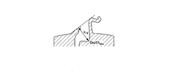
- the human perceives the left-right direction and the front-back and up-down directions using the interaural difference and the first notch N1 and the second notch N2 included in the head-related transfer function as clues. Therefore, if these cues are extracted or calculated from the head-related transfer functions and processed appropriately, three-dimensional sound image control becomes possible.
- the first notch N1 and the second notch N2 may not be clear depending on the listener and the sound source direction, and a method for easily and surely detecting the first notch N1 and the second notch N2 is required. .
- the head-related transfer function is generally affected by the pinna, the head, and the torso, but it is known that the first notch N1 and the second notch N2 are strongly affected by the pinna. ing.
- the present inventors filled each part of the pinna with clay, measured the head-related transfer function in the median plane and performed a sound image localization experiment, and filled the concha with the first notch N1 and the first notch N1. It has been found that the two notches N2 have disappeared and the sound image localization accuracy has significantly deteriorated.
- the present inventors have conducted intensive research to extract a part of the head impulse response by changing the cut-out time window length, and observed the appearance process of the first notch N1 and the second notch N2. As a result, the present inventors have found that the first notch N1 and the second notch N2 can be clearly detected by cutting out and analyzing about the initial 1 ms of the head impulse response. This is presumably because the response from the head or torso arrived, that is, only the response of the pinna was observed. About 1 ms of the initial head impulse response is the initial head impulse response, and the initial head impulse response obtained by Fourier transforming the initial head impulse response is the initial head related transfer function in the present invention.
- the head-related transfer function amplitude value generation unit 13 compares the pinna shapes x 1 to x 13 (see FIGS. 5A to 5C) of the listener with the pinna shape acquired by the pinna shape acquisition unit 11. Based on the multiple regression coefficient data acquired by the regression coefficient data acquisition unit 12, the amplitude value of the head-related transfer function at each frequency in each direction is calculated. More specifically, the head-related transfer function amplitude value generation unit 13 calculates each pinna shape x i (s) of the listener s and a multiple regression coefficient a i ( ⁇ , f) ( ⁇ is a rising angle, f is a frequency). Then, the amplitude value L (s, ⁇ , f) of the head-related transfer function of each frequency in each direction is calculated based on the following Expression 1.
- L (s, ⁇ , f) the amplitude value of the head-related transfer function of each frequency in each direction using the pinna shapes x 1 to x 13 shown in FIGS. 5A to 5C.
- n the value of n is “13”.
- ". b ( ⁇ , f) is a constant term.
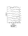
- FIG. 8 is a diagram illustrating the amplitude value of the head-related transfer function generated by the head-related transfer function amplitude value generation unit 13.
- the vertical axis of FIG. 8 indicates the relative amplitude [dB], and the horizontal axis of FIG. 8 indicates the frequency [Hz].
- the solid line indicates the pinna shapes x 1 to x 13 of the listener s (see FIGS. 5A to 5C) and the pinna shapes x 1 to x 13 at each frequency in each direction.
- the amplitude value L (s, ⁇ , f) of the head-related transfer function generated (calculated) by the transfer function amplitude value generation unit 13 is shown.
- the dotted lines indicate the pinna shapes x 1 to x 13 (see FIGS. 5A to 5C) of the listener s and the pinna shapes x 1 to x 13 as explanatory variables at each frequency in each direction.
- the head-related transfer function amplitude value generation unit 13 Shows the amplitude value L (s, ⁇ , f) of the head-related transfer function generated (calculated).
- the “initial head-related transfer function” in which the amplitude value is set as the target variable is obtained by cutting out about 1 ms of the initial head impulse response as the initial head impulse response, This is a Fourier transform of the impulse response.
- the “head-related transfer function” in which the amplitude value is used as the target variable is obtained by cutting out the entire head impulse response (5.3 ms) as a head impulse response and performing a Fourier transform on the head impulse response.
- FIG. 9 is a flowchart for explaining an example of processing executed when the head-related transfer function generation device 1 of the first embodiment generates an amplitude value L (s, ⁇ , f) of a head-related transfer function. .
- step S1 the pinna shape x 1 to x 13 of the listener s (see FIGS. 5A to 5C) or the pinna shape of the listener s by any of the methods described above.
- x 1 to x 8 and x 10 see FIG. 6
- the pinna shape x 9 of the listener s see FIG. 5B
- the pinna shape x 1 to x 14 of the listener s see FIGS.
- step S2 the pinna shape acquisition unit 11 sets the pinna shapes x 1 to x 13 of the listener s measured in step S1, or the pinna shapes x 1 to x 10 of the listener s, or The pinna shapes x 1 to x 14 of the listener s are obtained. Also, in step S3, for example, the auricle shapes x 1 to x 13 , or the auricle shapes x 1 to x 10 , or the auricle shape at each frequency in each direction by a multiple regression coefficient data generation unit (not shown).
- a multiple regression coefficient a obtained by performing a multiple regression analysis using the intermediary shapes x 1 to x 14 as explanatory variables and the amplitude value of the head-related transfer function or the initial head-related transfer function as the objective variable is converted into data.
- Certain multiple regression coefficient data is generated.
- step S4 the multiple regression coefficient data generated in step S3 is stored in, for example, a multiple regression coefficient database (not shown).
- step S5 the multiple regression coefficient data acquisition unit 12 acquires multiple regression coefficient data stored in the multiple regression coefficient database.
- step S6 the pinna shapes x 1 to x 13 of the listener s obtained in step S2, the pinna shapes x 1 to x 10 of the listener s, or the pinna shape x of the listener s and 1 ⁇ x 14, and multiple regression coefficient data obtained in step S5, on the basis of the equation 1 described above, the HRTF amplitude value generator 13, the amplitude of the head-related transfer function of the frequency in each direction
- the value L (s, ⁇ , f) is calculated (generated).
- the head-related transfer function generation device 1 of the first embodiment the head-related transfer function of the listener is not actually measured, but the pinna shape of the listener and the multiple regression coefficient data prepared in advance Then, the head-related transfer function amplitude value generation unit 13 calculates the amplitude value L (s, ⁇ , f) of the head-related transfer function at each frequency in each direction.
- the inventor of the present invention has earnestly studied that it is possible to calculate the amplitude value L (s, ⁇ , f) of the head-related transfer function with high accuracy equivalent to the amplitude value of the head-related transfer function of the listener actually measured. I found it.
- FIG. 10A and 10B are diagrams showing a comparison between the actually measured amplitude value of the head-related transfer function of the listener and the amplitude value of the head-related transfer function generated by the head-related transfer function generation device 1. is there.
- FIG. 10A is generated using multiple regression coefficient data obtained by performing multiple regression analysis using the pinna shapes x 1 to x 13 as explanatory variables and (all sections) the amplitude value of the head-related transfer function as an objective variable.
- FIG. 9 is a diagram showing the amplitude value of the head-related transfer function obtained. In detail, FIG.
- FIG. 10A shows the amplitude value (solid line) of the head-related transfer function actually measured for the sound source whose rising angle ⁇ in the median plane is 0 [°] and generated by the head-related transfer function generator 1.
- the head-related transfer function dotted line
- FIG. 10B shows a head generated using multiple regression coefficient data obtained by performing multiple regression analysis using the pinna shapes x 1 to x 13 as explanatory variables and using the amplitude value of the initial head-related transfer function as an objective variable. It is a figure showing the amplitude value of a partial transfer function.
- FIG. 10B shows the amplitude value (solid line) of the head-related transfer function actually measured for a sound source having a rising angle ⁇ in the median plane of 0 [°] and the head-related transfer function generator 1 generates the amplitude value.
- the amplitude value (dotted line) of the head-related transfer function generated by the head-related transfer function generation device 1 An amplitude value (solid line) of the head-related transfer function actually measured for a sound source whose elevation angle ⁇ is 120 [°] and an amplitude value (dotted line) of the head-related transfer
- the head-related transfer function generation device 1 of the first embodiment it is not necessary to actually measure the head-related transfer function of the listener himself, and the listener actually measured A head transfer function (dotted line in FIGS. 10A and 10B) that is as accurate as the person's head transfer function (solid line in FIGS. 10A and 10B) can be easily obtained.
- the head-related transfer function generation device 1 of the first embodiment does not need to actually measure the head-related transfer function of the listener himself, does not need to listen to the listener himself, and generates the head-related transfer function.
- the head-related transfer function suitable for the listener can be generated without the device 1 having to have a multiple regression coefficient database.
- the head-related transfer function generator is used. By using the head-related transfer function obtained by (1), three-dimensional sound reproduction and sound VR can be realized with high accuracy.
- the head-related transfer function generator 1 of the second embodiment has the same configuration as the head-related transfer function generator 1 of the first embodiment described above, except for the points described below. Therefore, according to the head-related transfer function generation device 1 of the second embodiment, the same effects as those of the head-related transfer function generation device 1 of the above-described first embodiment can be obtained except for the points described below.
- FIG. 11 is a diagram illustrating an example of an outline of the head-related transfer function generation device 1 according to the second embodiment.
- the head-related transfer function generation device 1 similarly to the example illustrated in FIG. 4, the head-related transfer function generation device 1 includes an auricle shape acquisition unit 11, a multiple regression coefficient data acquisition unit 12, and a head-related transfer function amplitude value generation unit. 13 is provided.
- the head-related transfer function generation device 1 further includes a head impulse response generation unit 14.
- the head impulse response generator 14 performs an inverse Fourier transform on the amplitude value of the head-related transfer function of each frequency in each direction generated by the head-related transfer function amplitude value generator 13, thereby obtaining a head impulse response in each direction.
- the phase of each frequency is assumed to be, for example, a minimum phase system. Since the head-related transfer function generator 1 of the second embodiment includes the head impulse response generator 14, the head-related transfer function is as accurate as the actually measured head-related transfer function of the listener. Not only can the function be easily obtained, but it is not necessary to actually measure both the listener's own head impulse response and the listener's head-related transfer function. , A head impulse response with high accuracy equivalent to that of the head impulse response can be easily obtained.
- the head-related transfer function generator 1 of the third embodiment has the same configuration as the head-related transfer function generator 1 of the above-described second embodiment, except for the points described below. Therefore, according to the head-related transfer function generation device 1 of the third embodiment, the same effects as those of the head-related transfer function generation device 1 of the above-described second embodiment can be obtained, except for the following points.
- FIG. 12 is a diagram illustrating an example of an outline of the head-related transfer function generation device 1 according to the third embodiment.
- the head-related transfer function generation device 1 similarly to the example illustrated in FIG. 11, the head-related transfer function generation device 1 includes an auricle shape acquisition unit 11, a multiple regression coefficient data acquisition unit 12, and a head-related transfer function amplitude value generation unit. 13 and a head impulse response generator 14.
- the head-related transfer function generation device 1 further includes a multiple regression coefficient database 15.
- the multiple regression coefficient database 15 stores multiple regression coefficient data generated by, for example, a multiple regression coefficient data generation unit (not shown) provided outside the head-related transfer function generation device 1.
- the head-related transfer function generator 1 of the third embodiment is provided with the multiple regression coefficient database 15, it accesses a multiple regression coefficient database (not shown) provided outside the head-related transfer function generator 1. Without having to perform the measurement of the head-related transfer function of the listener itself, and easily obtain a head-related transfer function that is as accurate as the actually measured head-related transfer function of the listener. be able to.
- the head-related transfer function generator 1 of the fourth embodiment has the same configuration as the head-related transfer function generator 1 of the third embodiment described above, except for the points described below. Therefore, according to the head-related transfer function generation device 1 of the fourth embodiment, the same effects as those of the head-related transfer function generation device 1 of the above-described third embodiment can be obtained, except for the following points.
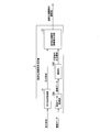
- FIG. 13 is a diagram illustrating an example of an outline of the head-related transfer function generation device 1 according to the fourth embodiment.
- the head-related transfer function generation device 1 includes an auricle shape acquisition unit 11, a multiple regression coefficient data acquisition unit 12, and a head-related transfer function amplitude value generation unit. 13, a head impulse response generator 14, and a multiple regression coefficient database 15.
- the head-related transfer function generation device 1 further includes a multiple regression coefficient data generation unit 16.
- the multiple regression coefficient data generation unit 16 uses the pinna shapes x 1 to x 13 , the pinna shapes x 1 to x 10 , or the pinna shapes x 1 to x 14 as explanatory variables at each frequency in each direction. Then, multiple regression coefficient data, which is obtained by converting a multiple regression coefficient a obtained by performing multiple regression analysis using the amplitude value of the head-related transfer function or the initial head-related transfer function as a target variable, is generated.
- the multiple regression coefficient data generated by the multiple regression coefficient data generator 16 is stored in the multiple regression coefficient database 15.
- the head-related transfer function generation device 1 of the fifth embodiment has substantially the same configuration as the head-related transfer function generation device 1 of the first embodiment described above, except for the points described below. Therefore, according to the head-related transfer function generation device 1 of the fifth embodiment, the same effects as those of the head-related transfer function generation device 1 of the above-described first embodiment can be obtained, except for the following points.
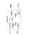
- FIG. 14 is a diagram illustrating an example of an outline of the head-related transfer function generation device 1 according to the fifth embodiment.
- the head-related transfer function generating device 1 includes an auricle shape obtaining unit 11, a multiple regression coefficient data obtaining unit 12, a head-related transfer function amplitude value generating unit 13, and a head impulse response generating unit 14, a head shape acquisition unit 17, and a head impulse response generation unit 18 with a binaural time difference.
- the pinna shape acquisition unit 11 is configured in the same manner as the pinna shape acquisition unit 11 shown in FIG. 4, and the pinna shapes x 1 to x 13 (see FIGS.
- the multiple regression coefficient data acquisition unit 12 is configured similarly to the multiple regression coefficient data acquisition unit 12 illustrated in FIG. 4 and acquires multiple regression coefficient data stored in, for example, a multiple regression coefficient database (not shown). I do.
- the multiple regression coefficient data indicates that each frequency (for example, the direction in which the elevation angle ⁇ in the median plane shown in FIG. 2A is 0 [°], the direction of 30 [°], etc.) is 0 [kHz shown in FIG.
- the pinna shapes x 1 to x 13 (see FIGS. 5A to 5C) or the pinna shapes x 1 to x 13 10 ) or multiple regression obtained by performing multiple regression analysis using the pinna shapes x 1 to x 14 (see FIGS. 7A to 7C) as explanatory variables and the amplitude value of the head-related transfer function as the objective variable. It is a data of coefficients.
- the head-related transfer function amplitude value generation unit 13 is configured similarly to the head-related transfer function amplitude value generation unit 13 illustrated in FIG. 4, and includes a pinna shape x i (s) of the listener s and a multiple regression coefficient.
- the amplitude value L (s, ⁇ , f) of the head-related transfer function at each frequency in each direction is calculated. calculate.
- the head impulse response generator 14 is configured in the same manner as the head impulse response generator 14 shown in FIG. 11, and transmits the head transfer of each frequency in each direction generated by the head transfer function amplitude value generator 13.
- the head impulse response in each direction is calculated by performing an inverse Fourier transform on the amplitude value of the function.
- the phase of each frequency is assumed to be, for example, a minimum phase system.
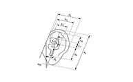
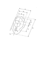
- the head shape acquisition unit 17 acquires the listener's head shapes p1 to p7 (see FIGS. 15A to 15C).
- FIGS. 15A to 15C show the listener's head shape (measurement of the listener's head and each measurement site around it) acquired by the head shape acquisition unit 17 of the head-related transfer function generation device 1 of the fifth embodiment.
- FIG. 9 is a diagram for explaining an example of a value.
- FIG. 15A is a front view of the listener for explaining the listener's head shape p1, p6 l, p6 r, p7.
- FIG. 15B is a diagram showing the listener's left side head for explaining the listener's head shapes p2 and p3.
- 15C is a diagram illustrating the top of the listener's head for describing the listener's head shapes p4 l , p4 r , p5 l , and p5 r .
- 15A to 15C the suffix “l” indicates the left ear, and the suffix “r” indicates the left ear.
- the head shapes p1 to p7 (see FIGS. 15A to 15C) of the listener acquired by the head shape acquiring unit 17 are transmitted from the listener's head and its surroundings to a tactile meter, a tape measure, or the like. It was measured using.
- an image of the listener's head and its surroundings is taken, and then the listener's head shapes p1 to p7 are measured using the image.
- the head shapes p1 to p7 of the listener are acquired by the head shape acquiring unit 17.
- the head impulse response generation unit 18 with the interaural time difference includes an interaural time difference calculation unit 18A and an interaural time difference addition unit 18B.
- the interaural time difference calculation unit 18A calculates an interaural time difference ITD (interaural time difference).
- the interaural time difference calculating unit 18A calculates the head shape p i (s) (p1 to p7) of the listener s acquired by the head shape acquiring unit 17 (see FIGS. 15A to 15C),
- the interaural time difference ITD (s, ⁇ ) of the listener s is calculated based on the multiple regression coefficient a i ( ⁇ ) and the following equation 2.
- Equation 2 ⁇ [°] is a lateral angle (see FIG. 1).
- ITD interaural time difference
- the interaural time difference calculation unit 18A calculates the head shape p1 (interaural distance D) of the listener s acquired by the head shape acquisition unit 17, the sound velocity c, and the following equation (3). , The binaural time difference ITD (s, ⁇ ) is calculated.
- the interaural time difference adding unit 18B adds the listener s calculated by the interaural time difference calculating unit 18A to the head impulse response in each direction generated by the head impulse response generating unit 14. Is added to the interaural time difference ITD (s, ⁇ ).
- the head-related transfer function generation device 1 of the fifth embodiment it is not necessary to actually measure the head-related transfer function of the listener, and the accuracy is as high as that of the actually measured head-related transfer function of the listener.
- the head related transfer function can be easily obtained, and the head impulse response of the listener himself added with the interaural time difference ITD (s, ⁇ ) of the listener himself can be obtained with high precision and ease.
- FIG. 16 is a diagram illustrating an example of an outline of the head-related transfer function generation device 1 according to the sixth embodiment.
- the head-related transfer function generation device 1 includes an auricle shape acquisition unit 11, a teacher data acquisition unit 19A, a learning unit 19B, and a head-related transfer function amplitude value generation unit 13. .
- the pinna shape acquisition unit 11 outputs the pinna shapes x 1 to x 13 (see FIGS. 5A to 5C) or the pinna shapes x 1 to x 10 of the listener or the pinna shapes x 1 to x 14. (See FIGS. 7A to 7C).
- the teacher data acquisition unit 19A acquires teacher data including the pinna shape of a predetermined listener and the amplitude value of the head-related transfer function of the predetermined listener.
- the learning unit 19B learns the correspondence between the pinna shape and the amplitude value of the head-related transfer function by using the teacher data acquired by the teacher data acquiring unit 19A.
- the learning unit 19B includes, for example, an NN (Neural Network) having an input layer, a hidden layer (hidden layer), and an output layer, and a DNN (Deep Neural Network) having an input layer, a plurality of hidden layers (hidden layers), and an output layer. And so on.
- the learning unit 19B outputs the correspondence between the pinna shape after learning and the amplitude value of the head-related transfer function to the head-related transfer function amplitude value generation unit 13.
- the head-related transfer function amplitude value generation unit 13 associates the pinna shape acquired by the pinna shape acquisition unit 11 with the pinna shape after learning output from the learning unit 19B and the amplitude value of the head-related transfer function. Based on the relationship, the amplitude value of the head-related transfer function of each frequency in each direction (see FIGS. 10A and 10B) is calculated.
- the head-related transfer function generation device 1 of the sixth embodiment similarly to the head-related transfer function generation device 1 of the first embodiment, it is not necessary to actually measure the head-related transfer function of the listener, and the measurement is actually performed. It is possible to easily obtain a highly accurate head-related transfer function equivalent to the measured head-related transfer function of the listener.
- an output signal y (t) at a certain time t is a product x ( ⁇ ) h (t) of an input signal x ( ⁇ ) at a time ⁇ and an impulse response at a time (t ⁇ ) calculated from ⁇ . ⁇ ) for all ⁇ .
- the output signal y (t) when the signal x (t) is input to the system of the impulse response h (t) is the sum of all the x ( ⁇ ) h (t ⁇ ) that reach the time t. It is represented by
- the convolution on the time axis is a multiplication of the sound source signal and the complex spectrum of the impulse response on the frequency axis. Compared to the amount of calculation on the time axis, the number is significantly reduced.
- the three-dimensional space characteristic of the original sound field can be reproduced in another space beyond time and space, or an arbitrary three-dimensional space characteristic can be obtained. Can be generated.
- the whole or a part of the function of each unit included in the head-related transfer function generation device 1 in the above-described embodiment is obtained by recording a program for realizing these functions on a computer-readable recording medium. May be realized by causing a computer system to read and execute the program recorded in the computer.
- the “computer system” includes an OS and hardware such as peripheral devices.
- the “computer-readable recording medium” refers to a portable medium such as a flexible disk, a magneto-optical disk, a ROM, and a CD-ROM, and a storage unit such as a hard disk built in a computer system.
- a “computer-readable recording medium” refers to a communication line for transmitting a program via a network such as the Internet or a communication line such as a telephone line, which dynamically holds the program for a short time.
- a program may include a program that holds a program for a certain period of time, such as a volatile memory in a computer system serving as a server or a client in that case.
- the above-mentioned program may be for realizing a part of the above-mentioned functions, or may be for realizing the above-mentioned functions in combination with a program already recorded in a computer system.
- SYMBOLS 1 Head-related transfer function generator, 11 ... Pinna shape acquisition part, 12 ... Multiple regression coefficient data acquisition part, 13 ... Head-related transfer function amplitude value generation part, 14 ... Head impulse response generation part, 15 ... Multiple regression Coefficient database, 16: multiple regression coefficient data generation unit, 17: head shape acquisition unit, 18: head impulse response generation unit with interaural time difference, 18A: interaural time difference calculation unit, 18B: interaural time difference addition Section, 19A: teacher data acquisition section, 19B: learning section
Landscapes
- Physics & Mathematics (AREA)
- Engineering & Computer Science (AREA)
- Acoustics & Sound (AREA)
- Multimedia (AREA)
- Stereophonic System (AREA)
Abstract
L'invention concerne un dispositif pour générer une fonction de transfert associée à la tête, comprenant : une unité d'acquisition de forme de pavillon d'oreille destinée à acquérir la forme d'un pavillon d'oreille d'un auditeur ; et une unité de génération de valeur d'amplitude de fonction de transfert associée à la tête destinée à calculer la valeur d'amplitude d'une fonction de transfert associée à la tête de chaque fréquence dans chaque direction sur la base de la forme du pavillon d'oreille acquise par l'unité d'acquisition de forme de pavillon d'oreille et de données de coefficient de régression multiple obtenues par numérisation d'un coefficient de régression multiple obtenu par une analyse de régression multiple en utilisant la forme de pavillon d'oreille comme variable explicative et la valeur d'amplitude de la fonction de transfert associée à la tête ou d'une fonction de transfert associée à la tête initiale en tant que variable objective, ou une corrélation entre la valeur d'amplitude de la fonction de transfert associée à la tête et la forme du pavillon d'oreille après avoir réalisé l'apprentissage en utilisant les données d'apprentissage.
Applications Claiming Priority (2)
| Application Number | Priority Date | Filing Date | Title |
|---|---|---|---|
| JP2018-127146 | 2018-07-03 | ||
| JP2018127146 | 2018-07-03 |
Publications (1)
| Publication Number | Publication Date |
|---|---|
| WO2020008655A1 true WO2020008655A1 (fr) | 2020-01-09 |
Family
ID=69059566
Family Applications (1)
| Application Number | Title | Priority Date | Filing Date |
|---|---|---|---|
| PCT/JP2018/029903 Ceased WO2020008655A1 (fr) | 2018-07-03 | 2018-08-09 | Dispositif pour générer une fonction de transfert associée à la tête, procédé pour générer une fonction de transfert associée à la tête, et programme |
Country Status (1)
| Country | Link |
|---|---|
| WO (1) | WO2020008655A1 (fr) |
Citations (1)
| Publication number | Priority date | Publication date | Assignee | Title |
|---|---|---|---|---|
| JP2008527821A (ja) * | 2005-01-10 | 2008-07-24 | フランス テレコム | モデル化によってhrtfを個別化するための方法および装置 |
-
2018
- 2018-08-09 WO PCT/JP2018/029903 patent/WO2020008655A1/fr not_active Ceased
Patent Citations (1)
| Publication number | Priority date | Publication date | Assignee | Title |
|---|---|---|---|---|
| JP2008527821A (ja) * | 2005-01-10 | 2008-07-24 | フランス テレコム | モデル化によってhrtfを個別化するための方法および装置 |
Non-Patent Citations (3)
| Title |
|---|
| ISHII, YOHJI: "Personalization of interaural difference cues based on the anthropometry of the listener's head", TRANSACTIONS OF THE VIRTUAL REALITY SOCIETY OF JAPAN, vol. 22, no. 3, 2017, pages 405 - 412, XP055669183 * |
| NISHINO, TAKANORI: "Estimating head related transfer function using multiple regression analysis", THE TRANSACTIONS OF THE INSTITUTE OF ELECTRONICS, INFORMATION AND COMMUNICATION ENGINEERS, vol. J84-A, no. 3, March 2001 (2001-03-01), pages 260 - 268 * |
| YANO, AKIHIRO: "Prediction of HRTF using neural network", PROCEEDINGS OF THE 2014 SPRING MEETING OF THE ACOUSTICAL SOCIETY OF JAPAN, March 2014 (2014-03-01), pages 885 - 886 * |
Similar Documents
| Publication | Publication Date | Title |
|---|---|---|
| US10939225B2 (en) | Calibrating listening devices | |
| KR102433613B1 (ko) | 개인 특징을 반영한 바이노럴 오디오 신호 처리 방법 및 장치 | |
| Keyrouz | Advanced binaural sound localization in 3-D for humanoid robots | |
| CN113889125B (zh) | 音频生成方法、装置、计算机设备和存储介质 | |
| US20170332186A1 (en) | Systems and methods of calibrating earphones | |
| Spagnol et al. | Current use and future perspectives of spatial audio technologies in electronic travel aids | |
| Udesen et al. | The effect of vision on psychoacoustic testing with headphone-based virtual sound | |
| MacDonald | A localization algorithm based on head-related transfer functions | |
| Bujacz et al. | Sound of Vision-Spatial audio output and sonification approaches | |
| Hwang et al. | Sound direction estimation using an artificial ear for robots | |
| JP6587047B2 (ja) | 臨場感伝達システムおよび臨場感再現装置 | |
| Geronazzo et al. | Auditory navigation with a tubular acoustic model for interactive distance cues and personalized head-related transfer functions: An auditory target-reaching task | |
| Zhang et al. | Platform for dynamic virtual auditory environment real-time rendering system | |
| Gamper | Enabling technologies for audio augmented reality systems | |
| Steffens et al. | Auditory orientation and distance estimation of sighted humans using virtual echolocation with artificial and self-generated sounds | |
| JP2018152834A (ja) | 仮想聴覚環境において音声信号出力を制御する方法及び装置 | |
| Yuan et al. | Sound image externalization for headphone based real-time 3D audio | |
| KR100927637B1 (ko) | 거리측정을 통한 가상음장 구현방법 및 그 기록매체 | |
| WO2020008655A1 (fr) | Dispositif pour générer une fonction de transfert associée à la tête, procédé pour générer une fonction de transfert associée à la tête, et programme | |
| Yu et al. | Effect of individualized head-related transfer functions on distance perception in virtual reproduction for a nearby sound source | |
| US11337021B2 (en) | Head-related transfer function generator, head-related transfer function generation program, and head-related transfer function generation method | |
| JP6986778B2 (ja) | 頭部伝達関数生成装置、頭部伝達関数生成プログラム及び頭部伝達関数生成方法 | |
| Tonnesen et al. | 3D sound synthesis | |
| Chen et al. | Individualization of head related impulse responses using division analysis | |
| Nambu et al. | Reinforcement-learning-based personalization of head-related transfer functions |
Legal Events
| Date | Code | Title | Description |
|---|---|---|---|
| 121 | Ep: the epo has been informed by wipo that ep was designated in this application |
Ref document number: 18925453 Country of ref document: EP Kind code of ref document: A1 |
|
| NENP | Non-entry into the national phase |
Ref country code: DE |
|
| 122 | Ep: pct application non-entry in european phase |
Ref document number: 18925453 Country of ref document: EP Kind code of ref document: A1 |
|
| NENP | Non-entry into the national phase |
Ref country code: JP |