WO2020008676A1 - Véhicule de travail - Google Patents
Véhicule de travail Download PDFInfo
- Publication number
- WO2020008676A1 WO2020008676A1 PCT/JP2019/006309 JP2019006309W WO2020008676A1 WO 2020008676 A1 WO2020008676 A1 WO 2020008676A1 JP 2019006309 W JP2019006309 W JP 2019006309W WO 2020008676 A1 WO2020008676 A1 WO 2020008676A1
- Authority
- WO
- WIPO (PCT)
- Prior art keywords
- oil receiving
- receiving portion
- transmission
- arm
- fork
- Prior art date
- Legal status (The legal status is an assumption and is not a legal conclusion. Google has not performed a legal analysis and makes no representation as to the accuracy of the status listed.)
- Ceased
Links
Images



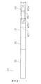
Classifications
-
- B—PERFORMING OPERATIONS; TRANSPORTING
- B60—VEHICLES IN GENERAL
- B60K—ARRANGEMENT OR MOUNTING OF PROPULSION UNITS OR OF TRANSMISSIONS IN VEHICLES; ARRANGEMENT OR MOUNTING OF PLURAL DIVERSE PRIME-MOVERS IN VEHICLES; AUXILIARY DRIVES FOR VEHICLES; INSTRUMENTATION OR DASHBOARDS FOR VEHICLES; ARRANGEMENTS IN CONNECTION WITH COOLING, AIR INTAKE, GAS EXHAUST OR FUEL SUPPLY OF PROPULSION UNITS IN VEHICLES
- B60K17/00—Arrangement or mounting of transmissions in vehicles
- B60K17/04—Arrangement or mounting of transmissions in vehicles characterised by arrangement, location or kind of gearing
- B60K17/06—Arrangement or mounting of transmissions in vehicles characterised by arrangement, location or kind of gearing of change-speed gearing
- B60K17/08—Arrangement or mounting of transmissions in vehicles characterised by arrangement, location or kind of gearing of change-speed gearing of mechanical type
-
- F—MECHANICAL ENGINEERING; LIGHTING; HEATING; WEAPONS; BLASTING
- F16—ENGINEERING ELEMENTS AND UNITS; GENERAL MEASURES FOR PRODUCING AND MAINTAINING EFFECTIVE FUNCTIONING OF MACHINES OR INSTALLATIONS; THERMAL INSULATION IN GENERAL
- F16H—GEARING
- F16H57/00—General details of gearing
- F16H57/04—Features relating to lubrication or cooling or heating
- F16H57/042—Guidance of lubricant
- F16H57/0421—Guidance of lubricant on or within the casing, e.g. shields or baffles for collecting lubricant, tubes, pipes, grooves, channels or the like
- F16H57/0423—Lubricant guiding means mounted or supported on the casing, e.g. shields or baffles for collecting lubricant, tubes or pipes
-
- F—MECHANICAL ENGINEERING; LIGHTING; HEATING; WEAPONS; BLASTING
- F16—ENGINEERING ELEMENTS AND UNITS; GENERAL MEASURES FOR PRODUCING AND MAINTAINING EFFECTIVE FUNCTIONING OF MACHINES OR INSTALLATIONS; THERMAL INSULATION IN GENERAL
- F16H—GEARING
- F16H57/00—General details of gearing
- F16H57/04—Features relating to lubrication or cooling or heating
- F16H57/042—Guidance of lubricant
- F16H57/0421—Guidance of lubricant on or within the casing, e.g. shields or baffles for collecting lubricant, tubes, pipes, grooves, channels or the like
- F16H57/0424—Lubricant guiding means in the wall of or integrated with the casing, e.g. grooves, channels, holes
-
- F—MECHANICAL ENGINEERING; LIGHTING; HEATING; WEAPONS; BLASTING
- F16—ENGINEERING ELEMENTS AND UNITS; GENERAL MEASURES FOR PRODUCING AND MAINTAINING EFFECTIVE FUNCTIONING OF MACHINES OR INSTALLATIONS; THERMAL INSULATION IN GENERAL
- F16H—GEARING
- F16H57/00—General details of gearing
- F16H57/04—Features relating to lubrication or cooling or heating
- F16H57/042—Guidance of lubricant
- F16H57/0432—Lubricant guiding means on or inside shift rods or shift forks
-
- F—MECHANICAL ENGINEERING; LIGHTING; HEATING; WEAPONS; BLASTING
- F16—ENGINEERING ELEMENTS AND UNITS; GENERAL MEASURES FOR PRODUCING AND MAINTAINING EFFECTIVE FUNCTIONING OF MACHINES OR INSTALLATIONS; THERMAL INSULATION IN GENERAL
- F16H—GEARING
- F16H57/00—General details of gearing
- F16H57/04—Features relating to lubrication or cooling or heating
- F16H57/0457—Splash lubrication
-
- F—MECHANICAL ENGINEERING; LIGHTING; HEATING; WEAPONS; BLASTING
- F16—ENGINEERING ELEMENTS AND UNITS; GENERAL MEASURES FOR PRODUCING AND MAINTAINING EFFECTIVE FUNCTIONING OF MACHINES OR INSTALLATIONS; THERMAL INSULATION IN GENERAL
- F16H—GEARING
- F16H57/00—General details of gearing
- F16H57/04—Features relating to lubrication or cooling or heating
- F16H57/0467—Elements of gearings to be lubricated, cooled or heated
- F16H57/0468—Shift rods or shift forks
-
- F—MECHANICAL ENGINEERING; LIGHTING; HEATING; WEAPONS; BLASTING
- F16—ENGINEERING ELEMENTS AND UNITS; GENERAL MEASURES FOR PRODUCING AND MAINTAINING EFFECTIVE FUNCTIONING OF MACHINES OR INSTALLATIONS; THERMAL INSULATION IN GENERAL
- F16H—GEARING
- F16H63/00—Control outputs from the control unit to change-speed- or reversing-gearings for conveying rotary motion or to other devices than the final output mechanism
- F16H63/02—Final output mechanisms therefor; Actuating means for the final output mechanisms
- F16H63/30—Constructional features of the final output mechanisms
- F16H63/32—Gear shift yokes, e.g. shift forks
-
- F—MECHANICAL ENGINEERING; LIGHTING; HEATING; WEAPONS; BLASTING
- F16—ENGINEERING ELEMENTS AND UNITS; GENERAL MEASURES FOR PRODUCING AND MAINTAINING EFFECTIVE FUNCTIONING OF MACHINES OR INSTALLATIONS; THERMAL INSULATION IN GENERAL
- F16H—GEARING
- F16H63/00—Control outputs from the control unit to change-speed- or reversing-gearings for conveying rotary motion or to other devices than the final output mechanism
- F16H63/02—Final output mechanisms therefor; Actuating means for the final output mechanisms
- F16H63/30—Constructional features of the final output mechanisms
- F16H63/32—Gear shift yokes, e.g. shift forks
- F16H2063/321—Gear shift yokes, e.g. shift forks characterised by the interface between fork body and shift rod, e.g. fixing means, bushes, cams or pins
Definitions
- the present invention relates to a work vehicle.
- the change of the transmission ratio in the transmission is performed by engaging a coupling sleeve, which is moved in the axial direction of the output shaft by a shift fork, with a desired transmission gear.
- Patent Literature 1 an oil receiving portion that opens upward is installed on a shift fork, and oil is supplied to an engagement portion between the shift fork and the coupling sleeve via a supply passage leading from the oil receiving portion to the coupling sleeve.
- An approach has been proposed.
- the oil receiving portion collects oil scattered in the transmission case.
- the present invention has an object to provide a transmission that can efficiently collect oil while suppressing an increase in the size of a fork, and a work vehicle including the same.
- a transmission according to the present invention includes a rotating shaft, a sleeve rotatable around an axis of the rotating shaft, a fork engaged with an outer periphery of the sleeve, and a shift disposed parallel to the rotating shaft and supporting the fork. And an axis.
- the fork has a support portion supported by the shift shaft, a first arm portion extending from the support portion in a circumferential direction of the rotation shaft, and disposed above the sleeve, and an oil receiver disposed on the first arm portion. And a part.
- the oil receiving portion includes a long hole extending in a direction perpendicular to the axial direction of the rotation shaft when viewed from above.
- a transmission including the transmission according to the present invention will be described with reference to the drawings.
- the transmission including the transmission according to the present invention can be applied to various vehicles such as work vehicles (construction vehicles, agricultural vehicles, transport vehicles, etc.), automobiles, motorcycles, and the like, and is particularly suitable for work vehicles. is there.
- work vehicles construction vehicles, agricultural vehicles, transport vehicles, etc.
- automobiles motorcycles, and the like
- up and down are terms based on the vertical direction.
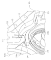
- FIGS. 1 and 2 are perspective views showing the internal structure of the transmission 100 according to the present embodiment.
- constituent members are appropriately omitted in order to illustrate main parts of the present invention.
- the transmission 100 includes the transmission case 10 and the transmission 20.
- Transmission case 10 The transmission case 10 houses the transmission 20. Inside the transmission case 10, oil is stored up to a predetermined height. A part of the transmission 20 is immersed in oil stored in the transmission case 10. The oil stored in the transmission case 10 is scattered into the case by the operation of the transmission 20, whereby the oil is supplied to the entire transmission 20.
- the transmission case 10 has a first inner wall 11 and a second inner wall 12.
- the first inner wall 11 extends along the vertical direction.
- the second inner wall 12 is continuous with the lower end of the first inner wall 11.
- the second inner wall 12 is inclined with respect to the first inner wall 11.
- the boundary 13 between the first inner wall 11 and the second inner wall 12 is formed in a convex shape toward the inside of the transmission case 10.
- the oil receiving portion 33 can collect not only oil dripping from the vicinity of the boundary portion 13 but also oil scattered in the transmission case 10.
- the transmission 20 includes a rotating shaft 21, a synchro hub 22, a coupling sleeve 23 (an example of a "sleeve"), a shift fork 24 (an example of a "fork”), and a shift shaft 25.
- the rotation shaft 21 is an output shaft of the transmission 20. In the present embodiment, the rotation shaft 21 extends in the horizontal direction.
- the synchro hub 22 is an annular member that surrounds the rotating shaft 21.
- the synchro hub 22 is fixed to the rotating shaft 21 by, for example, spline fitting.
- the coupling sleeve 23 is an annular member surrounding the sync hub 22.
- a gear 23a is formed on the inner peripheral surface of the coupling sleeve 23.
- the gear 23a of the coupling sleeve 23 meshes with the gear 22a of the synchro hub 22.
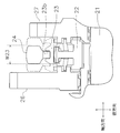
- FIG. 3 is a cross-sectional view of the transmission 20 parallel to the rotation shaft 21.
- transmission gears 26 and 27 are arranged on both sides of the coupling sleeve 23 in the axial direction of the rotating shaft 21. Each of the transmission gears 26 and 27 is loosely fitted to the rotating shaft 21.
- the coupling sleeve 23 moves toward the transmission gear 26 along the axial direction of the rotating shaft 21 and the coupling sleeve 23 synchronizes with the transmission gear 26, the rotation of the transmission gear 26 is synchronized via the coupling sleeve 23 to the synchro hub. 22. As a result, the rotation shaft 21 rotates.
- the shift fork 24 is an annular member that surrounds the coupling sleeve 23.
- the shift fork 24 is fixed to a shift shaft 25.
- the shift fork 24 is a member for moving the coupling sleeve 23 in the axial direction of the rotating shaft 21.
- the shift fork 24 is engaged with an engagement groove 23b (see FIG. 3) formed on the outer periphery of the coupling sleeve 23.
- the coupling sleeve 23 is a rotating member
- the shift fork 24 is a non-rotating member.
- the shift fork 24 As shown in FIG. 3, the shift fork 24 according to the present embodiment is disposed between the transmission gears 26 and 27 in the axial direction of the rotating shaft 21. Therefore, the movement range of the shift fork 24 is limited between the transmission gears 26 and 27. In the radial direction perpendicular to the axial direction of the rotating shaft 21, the outer diameter of the shift fork 24 is smaller than the outer diameter of the transmission gear 26 which is larger than the transmission gear 27. Thus, the transmission 20 is downsized by not projecting the shift fork 24 from the transmission gear 26.
- the outer diameter of the shift fork 24 is larger than the outer diameter of the transmission gear 27 in the radial direction, but may be smaller than the outer diameter of the transmission gear 27.
- the shift shaft 25 supports the shift fork 24.
- the shift shaft 25 is arranged parallel to the rotation shaft 21.
- the shift shaft 25 is movable in the axial direction of the rotation shaft 21.
- the shift shaft 25 is moved in the axial direction according to a shift change operation by an operator.
- the shift fork 24 moves in the axial direction of the rotating shaft 21.
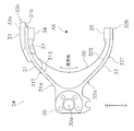
- FIG. 4 is a side view of the shift fork 24 as viewed from the axial direction of the rotating shaft 21.
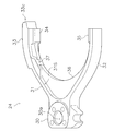
- FIG. 5 is a perspective view of the shift fork 24 as viewed from above.
- FIG. 6 is a perspective view of the shift fork 24 as viewed from below.
- the shift fork 24 includes a support portion 30, a first arm portion 31, a second arm portion 32, an oil receiving portion 33, a first claw portion 34, a second claw portion 35, a rib 36, an oil supply And a hole 37.
- the support part 30 is arranged between the first arm part 31 and the second arm part 32.
- the support 30 has an insertion hole 30a.
- the shift shaft 25 shown in FIG. 1 is inserted through the insertion hole 30a.
- the support portion 30 is supported and fixed to the shift shaft 25 inserted through the insertion hole 30a.
- the support force for supporting the shift fork 24 acts only between the shift shaft 25 and the support portion 30.
- the function of supporting the shift fork 24 is performed only by the support portion 30, and the first and second arms 31 and 32 do not have the function of supporting the shift fork 24. Accordingly, it can be said that a portion of the shift fork 24 on which the supporting force acts is the support portion 30, and portions on which the supporting force does not act are the first and second arm portions 31 and 32.
- the first arm portion 31 extends from the support portion 30 along a circumferential direction around the axis AX of the rotating shaft 21.
- the first arm 31 extends obliquely upward from the support 30.
- a proximal end 31a of the first arm 31 connected to the support 30 is a fixed end, and a distal end 31b opposite to the support 30 is a free end.
- the first arm 31 is disposed above the coupling sleeve 23 shown in FIG.
- the first arm portion 31 covers about 1/4 of the outer circumference of the coupling sleeve 23, but the entire length of the first arm portion 31 can be changed as appropriate.
- the first arm portion 31 has an inner peripheral surface 31S and an outer peripheral surface 31T.
- the inner peripheral surface 31S faces the coupling sleeve 23 shown in FIG.
- the outer peripheral surface 31T is provided on the opposite side of the inner peripheral surface 31S.
- Each of the inner peripheral surface 31S and the outer peripheral surface 31T extends in the circumferential direction.
- the second arm portion 32 extends from the support portion 30 along the circumferential direction around the axis AX of the rotating shaft 21.
- the second arm 32 extends obliquely downward from the support 30.
- a proximal end 32a of the second arm 32 connected to the support 30 is a fixed end, and a distal end 32b opposite to the support 30 is a free end.
- the second arm 32 is disposed below the coupling sleeve 23 shown in FIG.
- the second arm portion 32 covers about 1/4 of the outer circumference of the coupling sleeve 23, but the entire length of the second arm portion 32 can be changed as appropriate.
- the second arm 32 has an inner peripheral surface 32S and an outer peripheral surface 32T.
- the inner peripheral surface 32S faces the coupling sleeve 23 shown in FIG.
- the outer peripheral surface 32T is provided on the opposite side of the inner peripheral surface 32S.
- Each of the inner peripheral surface 32S and the outer peripheral surface 32T extends in the circumferential direction.
- the oil receiving portion 33 is disposed on the first arm portion 31.
- the oil receiving portion 33 is disposed on the outer peripheral surface 31T of the first arm portion 31.
- FIG. 7 is a top view of the shift fork 24 as viewed from above in the vertical direction.
- the oil receiving portion 33 has a long hole 33a extending in a direction perpendicular to the axial direction of the rotating shaft 21 (hereinafter, referred to as "vertical direction") when viewed from above.
- the long hole 33a is formed in the upper surface 33b of the oil receiving portion 33.
- the long hole 33a opens upward.
- the long hole 33a collects oil dripping from near the boundary 13 between the first inner wall 11 and the second inner wall 12 shown in FIG. 1 and oil scattered in the transmission case 10.
- the long hole 33a stores the collected oil.
- the oil stored in the long hole 33a is supplied to the outer peripheral surface of the coupling sleeve 23 via the oil supply hole 37.
- the length La of the elongated hole 33a in the vertical direction is larger than the maximum width Wa of the elongated hole 33a in the axial direction of the rotating shaft 21. Therefore, both the oil dripping from the vicinity of the boundary 13 and the oil scattered in the transmission case 10 can be efficiently collected, so that the lubrication of the coupling sleeve 23 can be favorably maintained.
- the length La of the elongated hole 33a is preferably 1.5 times or more the width Wa, and more preferably 2.0 times or more. Thereby, the oil collecting efficiency in the long hole 33a can be further improved.
- the first side surface 33p of the oil receiving portion 33 is smoothly connected to the first side surface 31p of the first arm portion 31. No bent step is provided between the first side surface 33p of the oil receiving portion 33 and the first side surface 31p of the first arm portion 31. In the present embodiment, the first side surface 33p of the oil receiving portion 33 is substantially flush with the first side surface 31p of the first arm portion 31.
- the second side surface 33q of the oil receiving portion 33 smoothly connects to the second side surface 31q of the first arm portion 31. No bent step is provided between the second side surface 33q of the oil receiving portion 33 and the second side surface 31q of the first arm portion 31. In the present embodiment, the second side surface 33q of the oil receiving portion 33 is substantially flush with the second side surface 31q of the first arm portion 31.
- the oil receiving portion 33 is disposed on the distal end portion 31 b of the first arm portion 31.
- the tip portion 33c of the oil receiving portion 33 projects from the tip portion 31b of the first arm portion 31 in the circumferential direction.
- the length of the distal end portion 33c of the oil receiving portion 33 projecting from the distal end portion 31b of the first arm portion 31 in the circumferential direction can be appropriately changed.
- the oil receiving portion 33 is located above the claw portion 34 in the vertical direction. Therefore, the oil receiving portion 33 overlaps the claw portion 34 in the vertical direction. In the present embodiment, only a part of the oil receiving portion 33 overlaps the claw portion 34 in the vertical direction. The length in the vertical direction where the oil receiving portion 33 overlaps the claw portion 34 can be changed as appropriate.
- the tip portion 33c of the oil receiving portion 33 protrudes from the claw portion 34 in the circumferential direction.
- the length of the distal end portion 33c of the oil receiving portion 33 protruding from the claw portion 34 in the circumferential direction can be appropriately changed.
- the oil receiving portion 33 is formed integrally with the first arm portion 31.
- the first arm portion 31 and the oil receiving portion 33 can be integrally formed by cutting a forged material component for the shift fork 24.
- the first claw portion 34 is disposed on the inner peripheral surface 31 ⁇ / b> S of the first arm portion 31.
- the second claw portion 35 is disposed on the inner peripheral surface 32S of the second arm portion 32.
- Each of the first claw portion 34 and the second claw portion 35 is engaged with the engagement groove 23b of the coupling sleeve 23 shown in FIG.
- the rib 36 extends from the inner peripheral surface 31S of the first arm 31 to the inner peripheral surface 32S of the second arm 32.
- the ribs 36 are arranged so as to be continuous from the first claw portion 34 to the second claw portion 35.
- the rib 36 is a member that reinforces the shift fork 24.
- the oil supply hole 37 communicates with the bottom surface of the long hole 33 a formed in the oil receiving portion 33 and the inner peripheral surface 31 ⁇ / b> S of the first arm 31.
- the oil supply hole 37 supplies the oil stored in the long hole 33a to the outer peripheral surface of the coupling sleeve 23.
- FIG. 8 is a development view in which the outer peripheral surface of the shift fork 24 is developed in a plane.
- the maximum width W33 of the oil receiving portion 33 is equal to or less than the maximum width W31 of the first arm portion 31.
- the maximum width W33 of the oil receiving portion 33 is substantially the same as the maximum width W31 of the first arm 31, but may be smaller than the maximum width W31 of the first arm 31.
- the maximum width W33 of the oil receiving portion 33 is smaller than the maximum width W23 of the coupling sleeve 23 (not shown in FIG. 8, see FIG. 3).
- the maximum width W33 of the oil receiving portion 33 is substantially the same as the maximum width W23 of the coupling sleeve 23, but may be smaller than the maximum width W23 of the coupling sleeve 23.
- the average width W24 of the entire shift fork 24 is smaller than the maximum width W33 ⁇ 10% of the oil receiving portion 33 and larger than the maximum width Wa of the long hole 33a.
- the average width W24 of the entire shift fork 24 is obtained by dividing the distance between two straight lines obtained by linearly approximating both end sides of the shift fork 24 in the axial direction by the least squares method. It is calculated by measuring at 10 points that divide the total length into 11 equal parts, and arithmetically averaging the measured values.
- the maximum width W33 ⁇ 10% of the oil receiving portion 33 means a range of 0.9 to 1.1 times the maximum width W33.
- the reason why the maximum width W33 of the oil receiving portion 33 has a range is that the forged material component for the shift fork 24 may be inevitably provided with a gradient, and that the material component is cut. This takes into account that an unavoidable step may be provided between the oil receiving portion 33 and the first arm portion 31 during processing.
- the shift fork 24 has an oil receiving portion 33 arranged on the first arm portion 31.
- the oil receiving portion 33 includes a long hole 33a extending in a direction perpendicular to the axis AX of the rotating shaft 21 in a top view. Therefore, oil dripping from the inner wall of the transmission case 10 and oil scattered inside the transmission case 10 can be efficiently collected while suppressing an increase in the size of the shift fork.
- the maximum width W33 of the oil receiving portion 33 is equal to or less than the maximum width W31 of the first arm portion 31. Therefore, the shift fork 24 can be made compact in the axial direction.
- the maximum width W33 of the oil receiving portion 33 is equal to or less than the maximum width W23 of the coupling sleeve 23. Accordingly, interference between the transmission gears 26 and 27 disposed on both sides of the coupling sleeve 23 and the oil receiving portion 33 can be suppressed, and the transmission 20 can be downsized by reducing the distance between the transmission gears 26 and 27. it can.
- the average width W24 of the shift fork 24 is smaller than the maximum width W33 ⁇ 10% of the oil receiving portion 33 and larger than the maximum width Wa of the long hole 33a. Therefore, the shift fork 24 can be made compact as a whole in the axial direction.
- the tip portion 33c of the oil receiving portion 33 protrudes from the claw portion 34 in the circumferential direction. Therefore, by increasing the length La of the long hole 33a, the efficiency of collecting oil in the long hole 33a can be further improved.
- a tip 33c of the oil receiving portion 33 protrudes from a tip 31b of the first arm 31 in the circumferential direction. Therefore, by increasing the length La of the long hole 33a, the efficiency of collecting oil in the long hole 33a can be further improved.
- the tip portion 33c of the oil receiving portion 33 protrudes from the claw portion 34 and the tip portion 31b of the first arm portion 31 in the circumferential direction, but the position of the oil receiving portion 33 is appropriately set. Can be changed.
- the oil receiving portion 33 is formed integrally with the first arm portion 31.
- the oil receiving portion 33 may be formed separately from the first arm portion 31.
- the oil receiving portion 33 is disposed below the boundary 13 between the first inner wall 11 and the second inner wall 12, but is disposed at a position shifted from below the boundary 13. Is also good. Even in this case, since the oil receiving portion 33 has the long holes 33a, it is possible to efficiently collect the oil.
- REFERENCE SIGNS LIST 100 transmission device 10 transmission case 11 first inner wall 12 second inner wall 13 boundary portion 20 transmission 21 rotation axis AX axis 22 synchro hub 23 coupling sleeve 24 shift fork 25 shift shaft 30 support portion 31 first arm portion 31b first One arm tip 32 Second arm 33 Oil receiving part 33a Slot 33b Upper surface 33c Oil receiving tip 34 First claw 35 Second claw 36 Rib 37 Oil supply hole Wa Maximum width W23 of long hole Maximum width of coupling sleeve W24 Average width of shift fork W31 Maximum width of first arm W33 Maximum width of oil receiving portion
Landscapes
- Engineering & Computer Science (AREA)
- General Engineering & Computer Science (AREA)
- Mechanical Engineering (AREA)
- Chemical & Material Sciences (AREA)
- Combustion & Propulsion (AREA)
- Transportation (AREA)
- General Details Of Gearings (AREA)
- Gear-Shifting Mechanisms (AREA)
Abstract
L'invention concerne une transmission (20) pourvue : d'un arbre rotatif (21) ; d'un manchon d'accouplement (23) susceptible de tourner autour de l'axe (AX) de l'arbre rotatif (21) ; d'une fourchette d'embrayage (24), qui vient en prise avec la circonférence extérieure du manchon d'accouplement (23) ; et d'un arbre de changement de vitesse (25), qui est disposé parallèlement à l'arbre rotatif (21) et qui soutient la fourchette d'embrayage (24). La fourchette d'embrayage (24) comprend : une partie de soutien (30), qui est soutenue par l'arbre de changement de vitesse (25) ; un premier bras (31), qui s'étend le long de la direction circonférentielle de l'arbre rotatif (21) à partir de la partie de soutien (30) et qui est disposé au-dessus du manchon d'accouplement (23) ; et un récepteur d'huile (33), qui est disposé sur le premier bras (31). Le récepteur d'huile (33) comprend un trou allongé (33a) qui, selon une vue de dessus, s'étend dans une direction perpendiculaire à la direction axiale de l'arbre rotatif (21).
Priority Applications (4)
| Application Number | Priority Date | Filing Date | Title |
|---|---|---|---|
| EP19830725.8A EP3751177A4 (fr) | 2018-07-03 | 2019-02-20 | Véhicule de travail |
| US16/979,578 US20210003215A1 (en) | 2018-07-03 | 2019-02-20 | Work vehicle |
| JP2020528682A JPWO2020008676A1 (ja) | 2018-07-03 | 2019-02-20 | 作業車両 |
| CN201980018420.3A CN111836981A (zh) | 2018-07-03 | 2019-02-20 | 工作车辆 |
Applications Claiming Priority (2)
| Application Number | Priority Date | Filing Date | Title |
|---|---|---|---|
| JP2018126841 | 2018-07-03 | ||
| JP2018-126841 | 2018-07-03 |
Publications (1)
| Publication Number | Publication Date |
|---|---|
| WO2020008676A1 true WO2020008676A1 (fr) | 2020-01-09 |
Family
ID=69060544
Family Applications (1)
| Application Number | Title | Priority Date | Filing Date |
|---|---|---|---|
| PCT/JP2019/006309 Ceased WO2020008676A1 (fr) | 2018-07-03 | 2019-02-20 | Véhicule de travail |
Country Status (5)
| Country | Link |
|---|---|
| US (1) | US20210003215A1 (fr) |
| EP (1) | EP3751177A4 (fr) |
| JP (1) | JPWO2020008676A1 (fr) |
| CN (1) | CN111836981A (fr) |
| WO (1) | WO2020008676A1 (fr) |
Families Citing this family (1)
| Publication number | Priority date | Publication date | Assignee | Title |
|---|---|---|---|---|
| CN112879558A (zh) * | 2021-02-06 | 2021-06-01 | 重庆凯瑞传动技术有限公司 | 换挡齿轮箱用无摩擦换挡机构 |
Citations (4)
| Publication number | Priority date | Publication date | Assignee | Title |
|---|---|---|---|---|
| JPS5460167U (fr) | 1977-10-04 | 1979-04-25 | ||
| JP2007139070A (ja) * | 2005-11-17 | 2007-06-07 | Aichi Mach Ind Co Ltd | 変速機 |
| JP2014095448A (ja) * | 2012-11-12 | 2014-05-22 | Honda Motor Co Ltd | シフトフォークの潤滑構造 |
| DE102016220306B3 (de) * | 2016-10-18 | 2017-12-28 | Audi Ag | Getriebeanordnung für ein Kraftfahrzeug |
Family Cites Families (4)
| Publication number | Priority date | Publication date | Assignee | Title |
|---|---|---|---|---|
| FR2836710B1 (fr) * | 2002-03-01 | 2005-06-03 | Renault | Fourchette de passage de vitesses |
| DE102007021686B4 (de) * | 2007-05-09 | 2017-01-19 | Audi Ag | Schmiervorrichtung für Geschwindigkeits-Wechselgetriebe |
| JP2010151184A (ja) * | 2008-12-24 | 2010-07-08 | Aisin Ai Co Ltd | トランスミッションのシフト装置 |
| JP2017219051A (ja) * | 2016-06-03 | 2017-12-14 | 本田技研工業株式会社 | 変速操作装置 |
-
2019
- 2019-02-20 JP JP2020528682A patent/JPWO2020008676A1/ja active Pending
- 2019-02-20 WO PCT/JP2019/006309 patent/WO2020008676A1/fr not_active Ceased
- 2019-02-20 EP EP19830725.8A patent/EP3751177A4/fr not_active Withdrawn
- 2019-02-20 CN CN201980018420.3A patent/CN111836981A/zh active Pending
- 2019-02-20 US US16/979,578 patent/US20210003215A1/en not_active Abandoned
Patent Citations (4)
| Publication number | Priority date | Publication date | Assignee | Title |
|---|---|---|---|---|
| JPS5460167U (fr) | 1977-10-04 | 1979-04-25 | ||
| JP2007139070A (ja) * | 2005-11-17 | 2007-06-07 | Aichi Mach Ind Co Ltd | 変速機 |
| JP2014095448A (ja) * | 2012-11-12 | 2014-05-22 | Honda Motor Co Ltd | シフトフォークの潤滑構造 |
| DE102016220306B3 (de) * | 2016-10-18 | 2017-12-28 | Audi Ag | Getriebeanordnung für ein Kraftfahrzeug |
Non-Patent Citations (1)
| Title |
|---|
| See also references of EP3751177A4 * |
Also Published As
| Publication number | Publication date |
|---|---|
| EP3751177A1 (fr) | 2020-12-16 |
| EP3751177A4 (fr) | 2021-10-27 |
| CN111836981A (zh) | 2020-10-27 |
| US20210003215A1 (en) | 2021-01-07 |
| JPWO2020008676A1 (ja) | 2021-07-08 |
Similar Documents
| Publication | Publication Date | Title |
|---|---|---|
| CN109483069A (zh) | 一种带有抽尘功能的卡盘 | |
| ITTO20110701A1 (it) | Metodo per la formatura di una dentatura frontale su un anello interno di un mozzo ruota | |
| WO2020008676A1 (fr) | Véhicule de travail | |
| CN104500715A (zh) | 行星轮系的润滑支路 | |
| CN105021398A (zh) | 一种自动变速箱跑合试验台 | |
| CN103016078A (zh) | 空气循环机轴支撑组件 | |
| JP2007512478A (ja) | 車両用変速機 | |
| JP2015521266A (ja) | フリーホイール装置 | |
| CN203857024U (zh) | 一种用于汽车变速箱的换挡轴总成 | |
| US11498362B2 (en) | Tone wheel assembly, an axle assembly made therewith, and a method of manufacturing an axle assembly | |
| CN104588787B (zh) | 汽车变速器齿轮剃齿夹具 | |
| FR2963747A1 (fr) | Ensemble comportant une fibre optique pour detecter un flan sur un serre-flan d'une presse d'emboutissage et serre-flan ainsi equipe | |
| CN215393612U (zh) | 定位对齿压具 | |
| CN205155030U (zh) | 换挡拉索配重块的连接卡子 | |
| CN207576809U (zh) | 在发动机油封内唇上涂润滑油的工具 | |
| CN101458145B (zh) | 用于流体旋转机械的转子的平衡组 | |
| CN211504521U (zh) | 一种电机标定测试用安装装置 | |
| CN109682606A (zh) | 车辆步进精度测量设备和车辆 | |
| CN223594714U (zh) | 曲轴组件、压缩机及车辆 | |
| CN202391978U (zh) | 轴承座 | |
| CN223424610U (zh) | 整体式单臂输出行星架和齿轮箱 | |
| CN208281452U (zh) | 一种传动系统内齿圈 | |
| CN106142533B (zh) | 一种护套管件装配工具 | |
| KR102477394B1 (ko) | 허브 캐리어 | |
| CN109058434B (zh) | 一种cg发动机曲轴箱传动系统的装配方法 |
Legal Events
| Date | Code | Title | Description |
|---|---|---|---|
| 121 | Ep: the epo has been informed by wipo that ep was designated in this application |
Ref document number: 19830725 Country of ref document: EP Kind code of ref document: A1 |
|
| ENP | Entry into the national phase |
Ref document number: 2020528682 Country of ref document: JP Kind code of ref document: A |
|
| ENP | Entry into the national phase |
Ref document number: 2019830725 Country of ref document: EP Effective date: 20200910 |
|
| NENP | Non-entry into the national phase |
Ref country code: DE |