WO2020008692A1 - Appareil et procédé de vulcanisation de pneus - Google Patents
Appareil et procédé de vulcanisation de pneus Download PDFInfo
- Publication number
- WO2020008692A1 WO2020008692A1 PCT/JP2019/014110 JP2019014110W WO2020008692A1 WO 2020008692 A1 WO2020008692 A1 WO 2020008692A1 JP 2019014110 W JP2019014110 W JP 2019014110W WO 2020008692 A1 WO2020008692 A1 WO 2020008692A1
- Authority
- WO
- WIPO (PCT)
- Prior art keywords
- mold
- plate
- side mold
- sector
- upper plate
- Prior art date
- Legal status (The legal status is an assumption and is not a legal conclusion. Google has not performed a legal analysis and makes no representation as to the accuracy of the status listed.)
- Ceased
Links
Images



Classifications
-
- B—PERFORMING OPERATIONS; TRANSPORTING
- B29—WORKING OF PLASTICS; WORKING OF SUBSTANCES IN A PLASTIC STATE IN GENERAL
- B29C—SHAPING OR JOINING OF PLASTICS; SHAPING OF MATERIAL IN A PLASTIC STATE, NOT OTHERWISE PROVIDED FOR; AFTER-TREATMENT OF THE SHAPED PRODUCTS, e.g. REPAIRING
- B29C33/00—Moulds or cores; Details thereof or accessories therefor
- B29C33/02—Moulds or cores; Details thereof or accessories therefor with incorporated heating or cooling means
-
- B—PERFORMING OPERATIONS; TRANSPORTING
- B29—WORKING OF PLASTICS; WORKING OF SUBSTANCES IN A PLASTIC STATE IN GENERAL
- B29C—SHAPING OR JOINING OF PLASTICS; SHAPING OF MATERIAL IN A PLASTIC STATE, NOT OTHERWISE PROVIDED FOR; AFTER-TREATMENT OF THE SHAPED PRODUCTS, e.g. REPAIRING
- B29C35/00—Heating, cooling or curing, e.g. crosslinking or vulcanising; Apparatus therefor
- B29C35/02—Heating or curing, e.g. crosslinking or vulcanizing during moulding, e.g. in a mould
Definitions
- the present invention relates to a tire vulcanizing apparatus and method, and more particularly, to a tire vulcanizing apparatus and method capable of more reliably closing a tire vulcanizing mold and producing a high quality tire. It is.
- the sectional type mold includes an upper side mold, a lower side mold, and a plurality of sector molds, and is closed so as to be in close contact with each other (for example, see Patent Document 1).
- Each sector mold is pressed toward the center mechanism by the container ring that moves downward, and is assembled in an annular shape.
- Each of the sector molds assembled in an annular shape and the lower side mold are assembled in close contact with each other.
- the upper side mold moves up and down together with the upper plate attached to the upper surface of the upper side mold. When the upper plate is disposed below the bolster plate to which the container ring is attached, the upper surface of the upper plate is pressed downward by the bolster plate when the mold is closed.
- a gap is easily generated between the lower surface of the bolster plate and the upper surface of the upper plate.
- the larger the gap is, the larger the amount of upward movement of the upper side mold together with the upper plate is increased, and the upper surface of each of the annularly assembled sector molds and the upper side mold are A gap occurs between the lower surface and the lower surface. That is, the mold cannot be maintained in a closed state without any gap.
- a step is formed on the upper side portion due to a gap between the upper surface of each sector mold and the lower surface of the upper side mold. Since there is a difference in the presence or absence of this step between the upper side portion and the lower side portion of the vulcanized tire, there is room for improvement in improving the tire quality.
- An object of the present invention is to provide a tire vulcanizing apparatus and a method capable of closing a tire vulcanizing mold more reliably and producing a tire of excellent quality.
- a tire vulcanizing apparatus of the present invention includes a segment attached to the outer peripheral surface of each of a plurality of sector molds arranged in a ring, an upper plate attached to an upper surface of an upper side mold, A lower plate attached to the lower surface of the side mold; a container ring disposed on the outer peripheral side of each segment; a bolster plate disposed above the upper plate and connected to the container ring; A pressurizing mechanism for moving the bolster plate, whereby the sector molds are annularly assembled between the upper plate and the lower plate, and these sector molds are attached to the upper side.
- a tire vulcanizing apparatus configured to be closed by being sandwiched vertically by a mold, the pressing mechanism and the sector mold, the upper side mold, and the lower side mold in a closed state. Independently has an upper closing mechanism for pressing the upper plate downward, and by activating the upper closing mechanism, the upper side molds are annularly assembled on the upper surfaces of the respective sector molds. Characterized in that it is configured to be pressed while maintaining the pressed state.
- a segment is attached to an outer peripheral surface of each of a plurality of sector molds arranged in a ring, an upper plate is attached to an upper surface of an upper side mold, and a lower plate is attached to a lower surface of a lower side mold.
- a container ring is arranged on the outer peripheral side of each segment, a bolster plate connected to the container ring is arranged above the upper plate, and a green tire is placed on the lower side mold sideways.
- the green tire in a tire vulcanizing method for vulcanizing by pressurizing and heating,
- the upper side mold In a state in which the sector mold, the upper side mold, and the lower side mold are closed, by operating an upper closing mechanism independent of the pressing mechanism, the upper side mold is It is characterized in that pressing is performed while maintaining a state of being annularly assembled on the upper surface of the sector mold.
- the upper side mold and the lower side mold are closed using the pressing mechanism, by operating the upper closing mechanism independent of the pressing mechanism, By moving the upper side mold downward, the upper side mold can be pressed while maintaining the state in which these sector molds are assembled on the upper surface of each sector mold.
- the gap can be eliminated or reduced by using the upper mold closing mechanism.
- the state in which each sector mold is assembled in an annular shape is maintained, it is advantageous to surely close the mold. Along with this, the difference in the finish of both side portions of the tire in the vulcanization process is less likely to occur, and a tire of excellent quality can be manufactured.
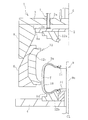
- FIG. 1 is an explanatory view exemplifying a left half of a tire vulcanizing apparatus of the present invention in an opened state in a longitudinal sectional view.
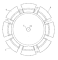
- FIG. 2 is an explanatory view illustrating the sector mold, the segment, and the upper closing mechanism of FIG. 1 in a plan view.
- FIG. 3 is an explanatory view exemplifying a state in which the bolster plate of FIG. 1 is moved downward and the segments are mounted on the lower plate in a longitudinal sectional view.
- FIG. 4 is an explanatory view exemplifying a state in which the bolster plate of FIG. 3 is further moved downward to assemble the respective sector molds in a ring shape in a longitudinal sectional view.
- FIG. 1 is an explanatory view exemplifying a left half of a tire vulcanizing apparatus of the present invention in an opened state in a longitudinal sectional view.
- FIG. 2 is an explanatory view illustrating the sector mold, the segment, and the upper closing mechanism of FIG
- FIG. 5 is an explanatory view exemplifying a state in which the mold is closed by operating the upper mold closing mechanism of FIG. 4 in a longitudinal sectional view.
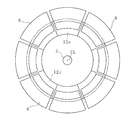
- FIG. 6 is an explanatory view illustrating the sector mold and the segment of FIG. 5 in plan view.
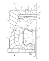
- FIG. 7 is an explanatory view exemplifying a left half of another embodiment of the vulcanizing apparatus in an opened state in a longitudinal sectional view.
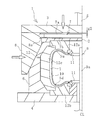
- FIG. 8 is an explanatory view exemplifying a state in which the mold is closed by operating the upper mold closing mechanism of FIG. 7 in a longitudinal sectional view.
- a tire vulcanizing apparatus 1 (hereinafter, referred to as a vulcanizing apparatus 1) of the present invention illustrated in FIGS. 1 and 2 includes a plurality of segments 6, an upper plate 2, a lower plate 4, a container ring 8, and a container ring.
- the bolster plate 3 includes a bolster plate 3, a pressure mechanism 5 for vertically moving the bolster plate 3, and a center mechanism 9 disposed at the center of the lower plate 4 in plan view.
- the vulcanizing apparatus 1 has an upper closing mechanism 7 that presses the upper plate 2 downward independently of the pressing mechanism 5.
- a tire vulcanizing mold 12 (hereinafter, referred to as a mold 12) is attached to the vulcanizing apparatus 1.
- the mold 12 includes an annular upper side mold 12a, an annular lower side mold 12b, and a plurality of sector molds 12c.
- the green tire T is placed on the lower side mold 12b and placed in the mold 12 in a sideways state. 1 and 2 illustrate a state where the mold 12 is open.
- the center post 9a constituting the center mechanism 9 is disposed at the center CL of the upper side mold 12a and the lower side mold 12b.
- a disk-shaped clamp portion 11 is attached to the center post 9a at an interval vertically.
- the upper end and the lower end of the cylindrical vulcanizing bladder 10 are gripped by the respective clamp portions 11.
- the upper plate 2 has the upper surface of the upper side mold 12a facing the lower surface thereof.
- the upper side mold 12a vulcanizes and molds the upper side part Su of the green tire T in a sideways state with its lower surface.
- the upper plate 2 moves up and down together with the upper side mold 12a.
- a lower surface of the upper side mold 12b is attached to an upper surface of the lower plate 4 so as to face the upper surface.
- the lower side mold 12b vulcanizes and forms the lower side portion Sd of the green tire T in a sideways state by its upper surface.
- the lower plate 4 is fixed to the ground base in a stationary state.
- Each segment 6 is annularly arranged around the center mechanism 9 (center CL).
- the outer peripheral surface of the sector mold 12c is attached to the inner periphery of each segment 6 so as to face each other.
- the outer peripheral surface of each segment 6 has a slope that is inclined upward from the outer peripheral side toward the inner peripheral side.
- the sector mold 12c vulcanizes and molds the tread portion of the green tire T in a sideways state by its inner peripheral surface.
- the annular container ring 8 is an annular body centered on the center mechanism 9 (center CL), and moves up and down on the outer peripheral side of the segments 6 arranged annularly. As the container ring 8 moves up and down, the inner peripheral inclined surface of the container ring 8 and the outer peripheral inclined surface of each segment 6 slide. Then, the outer peripheral surface of each segment 6 is pressed by the inner peripheral surface of the container ring 8 moving downward, so that each sector mold 12c moves closer to the annular center CL together with the segment 6.
- the bolster plate 3 is disposed above the upper plate 2 and is connected to the upper end of the container ring 8.
- a pressure mechanism 5 is connected to the upper surface of the bolster plate 3.
- a cylinder mechanism such as a hydraulic cylinder can be used as the pressurizing mechanism 5. The bolster plate 3 can be moved up and down by the vertical movement of the cylinder rod of the pressure mechanism 5.
- the upper closing mechanism 7 is arranged between the upper plate 2 and the bolster plate 3 in this embodiment.
- a cylinder mechanism such as a hydraulic cylinder can be used.
- the upper closing mechanism 7 can press the upper surface of the upper plate 2 and the lower surface of the bolster plate 3 by the vertical movement of the cylinder rod.
- the upper closing mechanism 7 has upper and lower flange portions 7a and 7b. Necessary components such as a heating plate and a heat insulating plate can be appropriately disposed between the upper closing mechanism 7 and the upper plate 2.
- the container ring 8 has an engaging portion 8a on its inner peripheral surface with which the upper plate 2 is directly or indirectly engaged.
- the lower flange portion 7b of the upper closing mechanism 7 is engaged with the engaging portion 8a protruding inward. Since the upper plate 2 is attached to the lower surface of the lower flange portion 7b, the upper plate 2 is indirectly engaged with the engaging portion 8a via the lower flange portion 7b. Thereby, in the opened state of the mold 12 illustrated in FIG. 1, the upper plate 2 is suspended from the container ring 8 via the engaging portion 8a.
- a predetermined gap g1 is formed between the upper closing mechanism 7 suspended from the container ring 8 and the bolster plate 3.
- the mold 12 When vulcanizing the green tire T, as shown in FIG. 1, the mold 12 is opened, and the green tire T in a sideways position is inserted through the center mechanism 9 to be expanded by shaping pressure. The green tire T is held by the bladder 10. The green tire T is placed on the lower side mold 12b.
- the bolster plate 3 is moved downward by the pressing mechanism 5, whereby the container ring 8, the upper plate 2, the upper side mold 12 a, and the upper closing mechanism 7 are integrally moved downward. . Thereby, each segment 6 is placed on the lower plate 4. In this step, a predetermined gap g1 is maintained between the upper closing mechanism 7 and the bolster plate 3.
- each sector mold 12c is annularly assembled between the upper plate 2 and the lower plate 4 between the upper and lower sides.
- each of the sector molds 12c assembled in an annular shape is divided into the upper side mold 12a and the lower side mold 12a.
- the mold 12 is sandwiched between the upper and lower sides of the green tire T, thereby closing the green tire T inside.
- the vulcanizing bladder 10 is further expanded inside the green tire T to apply a predetermined internal pressure to the green tire T and to perform vulcanization by heating at a predetermined temperature.
- the pneumatic tire is completed by vulcanizing the green tire T for a predetermined time.
- each sector mold 12 c can be pressed more strongly by the container ring 8. Therefore, the sector molds 12c that are adjacent to each other in the circumferential direction are assembled so as to be in close contact with each other, and a gap is hardly generated between the sector molds 12c.
- a predetermined gap g2 exists between the upper closing mechanism 7 and the bolster plate 3, when the vulcanizing bladder 10 is further expanded to apply a predetermined internal pressure to the green tire T, the upper side mold There is a possibility that the upper surface 12a may move away from the upper surface of each sector mold 12c by a gap g2.
- the upper closing mechanism 7 is operated independently of the pressurizing mechanism 5 to move the upper closing mechanism 7 to the upper plate 2 and the bolster plate. 3 to press the upper surface of the upper plate 2 and the lower surface of the bolster plate 3.
- the upper side mold 12a is pressed against the upper surface of each sector mold 12c.
- the vulcanizing apparatus 1 is easily made compact by arranging the upper closing mechanism 7 between the upper plate 2 and the bolster plate 3. Further, since the upper plate 2 is directly or indirectly engaged with the engaging portion 8a of the container ring 8 and suspended, the structure of the vulcanizing apparatus 1 is easily simplified.
- the upper closing mechanism 7 is not limited to the configuration illustrated in the above-described embodiment, and may employ a configuration illustrated in FIG. 7. This embodiment is different from the previous embodiment in the upper mold closing mechanism 7, and other configurations are substantially the same.
- the upper closing mechanism 7 is a cylinder mechanism such as a hydraulic cylinder that penetrates a through hole 3 a penetrating the bolster plate 3 up and down.
- the cylinder rod extends downward and presses the upper surface of the upper plate 2.
- a flange 2 a formed on the outer edge of the upper plate 2 is engaged with an engaging portion of the container ring 8. Therefore, the upper plate 2 is directly engaged with the engaging portion 8a. Thereby, in the open state of the mold 12 illustrated in FIG. 7, the upper plate 2 is suspended from the container ring 8 via the engaging portion 8a.
- the mold 12 When vulcanizing the green tire T, the mold 12 is closed using the pressing mechanism 5 as illustrated in FIG. When the upper side molds 12a that have moved downward together with the upper plate 2 are placed on the upper surfaces of the respective sector molds 12c, the suspended state of the upper plate 2 that has been suspended from the container ring 8 via the engaging portions 8a is set. It is released.
- the upper closing mechanism 7 is operated independently of the pressing mechanism 5 to press the upper surface of the upper plate 2 as illustrated in FIG. Thereby, the upper side mold 12a is pressed against the upper surface of each sector mold 12c.
- the gap g2 is eliminated by using the upper closing mechanism 7. Alternatively, it can be made smaller.
Landscapes
- Engineering & Computer Science (AREA)
- Mechanical Engineering (AREA)
- Physics & Mathematics (AREA)
- Health & Medical Sciences (AREA)
- Oral & Maxillofacial Surgery (AREA)
- Thermal Sciences (AREA)
- Moulds For Moulding Plastics Or The Like (AREA)
- Heating, Cooling, Or Curing Plastics Or The Like In General (AREA)
Abstract
L'invention concerne un appareil et un procédé de vulcanisation de pneus, avec lesquels des moules de vulcanisation de pneus peuvent être serrés de manière plus sûre et des pneus d'une excellente qualité peuvent être produits. Un anneau de récipient (8) est disposé sur le côté de circonférence externe de segments (6) montés sur les surfaces circonférentielles externes de moules de secteur (12c). Une plaque de traverse (3) est disposée au-dessus d'une plaque supérieure (2) montée sur la surface supérieure d'un moule latéral supérieur (12a). Un pneu cru est chargé latéralement sur un moule latéral inférieur (12b) monté sur la surface supérieure d'une plaque inférieure (4). Pendant le déplacement de la plaque de traverse (3) ainsi que de l'anneau de récipient (8) vers le bas en vue de serrer chacun des moules de secteur (12c) qui ont été assemblés en forme d'anneau depuis le dessus et le dessous avec les moules latéraux (12a, 12b) et de confiner et de serrer le pneu cru (T) à l'intérieur de ces derniers, le moule latéral supérieur (12a) est pressé sur la surface supérieure de chaque moule de secteur (12c) avec un mécanisme de serrage de moule supérieur (7) pendant le maintien de l'ensemble en forme d'anneau.
Applications Claiming Priority (2)
| Application Number | Priority Date | Filing Date | Title |
|---|---|---|---|
| JP2018126168A JP6604402B1 (ja) | 2018-07-02 | 2018-07-02 | タイヤ加硫装置および方法 |
| JP2018-126168 | 2018-07-02 |
Publications (1)
| Publication Number | Publication Date |
|---|---|
| WO2020008692A1 true WO2020008692A1 (fr) | 2020-01-09 |
Family
ID=68532210
Family Applications (1)
| Application Number | Title | Priority Date | Filing Date |
|---|---|---|---|
| PCT/JP2019/014110 Ceased WO2020008692A1 (fr) | 2018-07-02 | 2019-03-29 | Appareil et procédé de vulcanisation de pneus |
Country Status (2)
| Country | Link |
|---|---|
| JP (1) | JP6604402B1 (fr) |
| WO (1) | WO2020008692A1 (fr) |
Families Citing this family (1)
| Publication number | Priority date | Publication date | Assignee | Title |
|---|---|---|---|---|
| JP7469633B2 (ja) * | 2020-05-12 | 2024-04-17 | 横浜ゴム株式会社 | タイヤ加硫方法 |
Citations (2)
| Publication number | Priority date | Publication date | Assignee | Title |
|---|---|---|---|---|
| US20120177763A1 (en) * | 2009-07-01 | 2012-07-12 | Jean-Claude Aperce | Sector Mold with Radial Recoil |
| JP2017170643A (ja) * | 2016-03-18 | 2017-09-28 | 住友ゴム工業株式会社 | タイヤ加硫装置 |
-
2018
- 2018-07-02 JP JP2018126168A patent/JP6604402B1/ja active Active
-
2019
- 2019-03-29 WO PCT/JP2019/014110 patent/WO2020008692A1/fr not_active Ceased
Patent Citations (2)
| Publication number | Priority date | Publication date | Assignee | Title |
|---|---|---|---|---|
| US20120177763A1 (en) * | 2009-07-01 | 2012-07-12 | Jean-Claude Aperce | Sector Mold with Radial Recoil |
| JP2017170643A (ja) * | 2016-03-18 | 2017-09-28 | 住友ゴム工業株式会社 | タイヤ加硫装置 |
Also Published As
| Publication number | Publication date |
|---|---|
| JP2020001362A (ja) | 2020-01-09 |
| JP6604402B1 (ja) | 2019-11-13 |
Similar Documents
| Publication | Publication Date | Title |
|---|---|---|
| US3396221A (en) | Methods for the vulcanizing of preformed tires | |
| US3464090A (en) | Tire curing press | |
| JP4971887B2 (ja) | タイヤ加硫用コンテナ | |
| CN114126818A (zh) | 轮胎硫化装置及方法 | |
| JP2013103478A (ja) | ローカバー | |
| WO2020008692A1 (fr) | Appareil et procédé de vulcanisation de pneus | |
| US10576665B2 (en) | Tire vulcanizer | |
| JP3847463B2 (ja) | 空気ばね用ダイヤフラムの加硫金型 | |
| JP2017065232A (ja) | タイヤ加硫金型、タイヤ加硫装置及びタイヤの製造方法 | |
| JP6809443B2 (ja) | タイヤ加硫用コンテナの構造 | |
| JPH03253311A (ja) | ブラダ型・ブラダレス型兼用タイヤ加硫機 | |
| JP2010058396A (ja) | 空気ばね用ダイアフラムの製造方法および空気ばね用ダイアフラム | |
| JP3238268B2 (ja) | ブラダレスタイヤ加硫機の生タイヤ装着方法及び生タイヤ把持装置 | |
| CN112739514B (zh) | 轮胎硫化装置及方法 | |
| JP6130761B2 (ja) | タイヤ成型用金型及びタイヤ成型方法 | |
| JP7469633B2 (ja) | タイヤ加硫方法 | |
| JP6844203B2 (ja) | タイヤ加硫用コンテナ | |
| CN101600551B (zh) | 轮胎成形用双组合模具及使用该轮胎成形用双组合模具的轮胎的制造方法 | |
| WO2019039043A1 (fr) | Matrice pour moulage par vulcanisation de pneumatique | |
| JP7469638B2 (ja) | タイヤ加硫方法 | |
| JP4952925B2 (ja) | 空気入りタイヤの加硫成形方法及びその装置 | |
| JP6503824B2 (ja) | タイヤ加硫用コンテナ | |
| JP6753155B2 (ja) | 空気入りタイヤの製造方法および装置 | |
| JP2011116062A (ja) | 空気入りタイヤの加硫方法および加硫装置 | |
| JP2017217781A (ja) | タイヤ加硫用コンテナ |
Legal Events
| Date | Code | Title | Description |
|---|---|---|---|
| 121 | Ep: the epo has been informed by wipo that ep was designated in this application |
Ref document number: 19830088 Country of ref document: EP Kind code of ref document: A1 |
|
| NENP | Non-entry into the national phase |
Ref country code: DE |
|
| 122 | Ep: pct application non-entry in european phase |
Ref document number: 19830088 Country of ref document: EP Kind code of ref document: A1 |