WO2020008726A1 - 対象物体検出プログラム、および対象物体検出装置 - Google Patents
対象物体検出プログラム、および対象物体検出装置 Download PDFInfo
- Publication number
- WO2020008726A1 WO2020008726A1 PCT/JP2019/018629 JP2019018629W WO2020008726A1 WO 2020008726 A1 WO2020008726 A1 WO 2020008726A1 JP 2019018629 W JP2019018629 W JP 2019018629W WO 2020008726 A1 WO2020008726 A1 WO 2020008726A1
- Authority
- WO
- WIPO (PCT)
- Prior art keywords
- target object
- image
- region
- divided
- object detection
- Prior art date
- Legal status (The legal status is an assumption and is not a legal conclusion. Google has not performed a legal analysis and makes no representation as to the accuracy of the status listed.)
- Ceased
Links
Images





Classifications
-
- G—PHYSICS
- G06—COMPUTING OR CALCULATING; COUNTING
- G06T—IMAGE DATA PROCESSING OR GENERATION, IN GENERAL
- G06T7/00—Image analysis
- G06T7/70—Determining position or orientation of objects or cameras
- G06T7/73—Determining position or orientation of objects or cameras using feature-based methods
-
- G—PHYSICS
- G06—COMPUTING OR CALCULATING; COUNTING
- G06N—COMPUTING ARRANGEMENTS BASED ON SPECIFIC COMPUTATIONAL MODELS
- G06N3/00—Computing arrangements based on biological models
- G06N3/02—Neural networks
- G06N3/04—Architecture, e.g. interconnection topology
- G06N3/0464—Convolutional networks [CNN, ConvNet]
-
- G—PHYSICS
- G06—COMPUTING OR CALCULATING; COUNTING
- G06N—COMPUTING ARRANGEMENTS BASED ON SPECIFIC COMPUTATIONAL MODELS
- G06N3/00—Computing arrangements based on biological models
- G06N3/02—Neural networks
- G06N3/08—Learning methods
- G06N3/09—Supervised learning
-
- G—PHYSICS
- G06—COMPUTING OR CALCULATING; COUNTING
- G06V—IMAGE OR VIDEO RECOGNITION OR UNDERSTANDING
- G06V10/00—Arrangements for image or video recognition or understanding
- G06V10/20—Image preprocessing
- G06V10/25—Determination of region of interest [ROI] or a volume of interest [VOI]
-
- G—PHYSICS
- G06—COMPUTING OR CALCULATING; COUNTING
- G06V—IMAGE OR VIDEO RECOGNITION OR UNDERSTANDING
- G06V10/00—Arrangements for image or video recognition or understanding
- G06V10/40—Extraction of image or video features
- G06V10/44—Local feature extraction by analysis of parts of the pattern, e.g. by detecting edges, contours, loops, corners, strokes or intersections; Connectivity analysis, e.g. of connected components
- G06V10/443—Local feature extraction by analysis of parts of the pattern, e.g. by detecting edges, contours, loops, corners, strokes or intersections; Connectivity analysis, e.g. of connected components by matching or filtering
- G06V10/449—Biologically inspired filters, e.g. difference of Gaussians [DoG] or Gabor filters
- G06V10/451—Biologically inspired filters, e.g. difference of Gaussians [DoG] or Gabor filters with interaction between the filter responses, e.g. cortical complex cells
- G06V10/454—Integrating the filters into a hierarchical structure, e.g. convolutional neural networks [CNN]
-
- G—PHYSICS
- G06—COMPUTING OR CALCULATING; COUNTING
- G06V—IMAGE OR VIDEO RECOGNITION OR UNDERSTANDING
- G06V10/00—Arrangements for image or video recognition or understanding
- G06V10/40—Extraction of image or video features
- G06V10/50—Extraction of image or video features by performing operations within image blocks; by using histograms, e.g. histogram of oriented gradients [HoG]; by summing image-intensity values; Projection analysis
-
- G—PHYSICS
- G06—COMPUTING OR CALCULATING; COUNTING
- G06V—IMAGE OR VIDEO RECOGNITION OR UNDERSTANDING
- G06V10/00—Arrangements for image or video recognition or understanding
- G06V10/70—Arrangements for image or video recognition or understanding using pattern recognition or machine learning
- G06V10/82—Arrangements for image or video recognition or understanding using pattern recognition or machine learning using neural networks
-
- G—PHYSICS
- G06—COMPUTING OR CALCULATING; COUNTING
- G06V—IMAGE OR VIDEO RECOGNITION OR UNDERSTANDING
- G06V20/00—Scenes; Scene-specific elements
- G06V20/50—Context or environment of the image
- G06V20/52—Surveillance or monitoring of activities, e.g. for recognising suspicious objects
-
- G—PHYSICS
- G06—COMPUTING OR CALCULATING; COUNTING
- G06V—IMAGE OR VIDEO RECOGNITION OR UNDERSTANDING
- G06V40/00—Recognition of biometric, human-related or animal-related patterns in image or video data
- G06V40/10—Human or animal bodies, e.g. vehicle occupants or pedestrians; Body parts, e.g. hands
- G06V40/103—Static body considered as a whole, e.g. static pedestrian or occupant recognition
-
- G—PHYSICS
- G06—COMPUTING OR CALCULATING; COUNTING
- G06V—IMAGE OR VIDEO RECOGNITION OR UNDERSTANDING
- G06V40/00—Recognition of biometric, human-related or animal-related patterns in image or video data
- G06V40/20—Movements or behaviour, e.g. gesture recognition
-
- G—PHYSICS
- G06—COMPUTING OR CALCULATING; COUNTING
- G06N—COMPUTING ARRANGEMENTS BASED ON SPECIFIC COMPUTATIONAL MODELS
- G06N3/00—Computing arrangements based on biological models
- G06N3/02—Neural networks
- G06N3/04—Architecture, e.g. interconnection topology
- G06N3/045—Combinations of networks
-
- G—PHYSICS
- G06—COMPUTING OR CALCULATING; COUNTING
- G06T—IMAGE DATA PROCESSING OR GENERATION, IN GENERAL
- G06T2207/00—Indexing scheme for image analysis or image enhancement
- G06T2207/20—Special algorithmic details
- G06T2207/20021—Dividing image into blocks, subimages or windows
-
- G—PHYSICS
- G06—COMPUTING OR CALCULATING; COUNTING
- G06T—IMAGE DATA PROCESSING OR GENERATION, IN GENERAL
- G06T2207/00—Indexing scheme for image analysis or image enhancement
- G06T2207/20—Special algorithmic details
- G06T2207/20084—Artificial neural networks [ANN]
Definitions
- the present invention relates to a target object detection program and a target object detection device.
- Japan's life expectancy has been remarkably prolonged due to the improvement of living standards, improvement of sanitary conditions, and improvement of medical care standards following the postwar economic growth. For this reason, coupled with a decrease in the birth rate, the aging society has a high aging rate. In such an aging society, an increase in the number of care-requirers and the like who need to take care of care and the like due to illness, injury, and aging is expected.
- ⁇ ⁇ Care recipients may fall down while walking or fall out of bed and get injured in facilities such as hospitals and welfare facilities for the elderly. Therefore, a system for detecting the condition of a person requiring care or the like from a captured image so that staff such as a caregiver or a nurse can immediately rush to the care recipient or the like in such a state. Is being developed. In order to detect the state of a care recipient or the like in such a system, it is necessary to detect a detection target object (a target person or the like) from a captured image with high accuracy.
- a detection target object a target person or the like
- Patent Document 1 discloses the following technique.
- a plurality of images obtained by rotating a fisheye image taken by a fisheye camera by a predetermined angle are created, a plurality of images before and after rotation, and an image of a target object to be detected stored in a database in advance, The target object is detected by comparing.
- the target object can be detected with high accuracy from the fisheye image in which the distortion increases from the center of the image toward the periphery.
- Patent Document 2 discloses the following technology.
- a feature map is generated from the captured image using a deep neural network. Based on the feature map, a candidate rectangle, which is a region where an object is presumed to be present, is detected. Then, a target object is detected by calculating a reliability score for each candidate category for each candidate rectangle. Thus, by calculating both the candidate rectangle and the reliability score using one feature map generated from the entire captured image, the target object can be detected with high accuracy and high speed.
- Patent Literature 1 needs to generate a plurality of images obtained by rotating an input fisheye image, and requires a plurality of detection processes on the plurality of images, thereby increasing processing time. There is a problem of doing.
- Patent Literature 2 when a target object is detected from an image having relatively large image distortion such as a fisheye image, there is a possibility that erroneous detection of the target object due to the image distortion occurs. There is a problem that there is.
- the present invention has been made to solve such a problem. That is, it is an object of the present invention to provide a target object detection program and a target object detection device capable of reducing erroneous detection of a target object due to a change in an object for each region in a captured image and capable of detecting the target object at high speed and with high accuracy. Aim.
- a procedure (a) for acquiring a captured image a procedure (b) for generating a feature map from the image acquired in the procedure (a), and a divided area for dividing the image into a plurality of areas.
- a dictionary for detecting a target object corresponding to each divided region based on the region-based estimation parameters set, for each of the divided regions, using the dictionary corresponding to the divided region,
- a target object detection program for causing a computer to execute a process having a step (c) of detecting a target object from a feature map.
- the image is an image in which the ratio between the size of the object on the image and the actual size of the object changes in accordance with the distance from the camera that captured the image to the object in the shooting direction.
- a reliability score for each predetermined category of the object is calculated for each of the divided areas using the dictionary corresponding to the divided area, based on the estimated parameters for each area.
- the step (c) includes, for each of the divided regions, detecting an object from the feature map using the dictionary corresponding to the divided region, based on the region-based estimation parameters.
- C2 detecting the target object from the objects by calculating a reliability score for each predetermined category of the objects detected in the step (c1).
- the target object detection program according to any one of (1) to (3).
- the step (c) includes, for each of the divided regions, using the feature map and the dictionary, a shift amount and a scale of a position of a reference rectangle set in the image from a rectangular region where an object exists. Estimating the shift amount of the object, detecting the candidate rectangle including the object by minimizing the shift amount of the position and the shift amount of the scale, for each predetermined category of the object included in the candidate rectangle Calculating a reliability score, detecting the target object by outputting the candidate rectangle in which the category with the highest reliability score has become the category of the target object as an output rectangle including the target object,
- the target object detection program according to any one of (1) to (3), wherein the shape of the reference rectangle is different for each of the divided areas.
- the region-based estimation parameters used for detecting the target object correspond to the distortion characteristics of the lens.
- the area-based estimation parameter used for detecting the target object is set to correspond to the installation height of the camera.
- the area-based estimation parameter used for detecting the target object is set based on the size of the imaging range of the image.
- an acquisition unit that acquires a captured image; a feature map generation unit that generates a feature map from the acquired image; a divided region that divides the image into a plurality of regions; A dictionary for detecting the target object, and detecting the target object from the feature map, for each of the divided regions, using the dictionary corresponding to the divided region, based on the region-based estimation parameters set. And a detection unit that performs the detection.
- the image is an image in which the ratio of the size of the object on the image to the actual size of the object changes in accordance with the distance from the camera that captured the image to the object in the shooting direction.
- the detection unit calculates, for each of the divided regions, a reliability score for each predetermined category of the object based on the region-based estimation parameters, using the dictionary corresponding to the divided region.
- the target object detection device according to any one of (10) to (12), wherein the target object is detected.
- the detection unit detects, for each of the divided regions, an object from the feature map using the dictionary corresponding to the divided region, based on the region-specific estimation parameter; (10) to (12), including a target object detection unit that detects the target object from among the objects by calculating a reliability score for each of predetermined categories of the object detected by the detection unit.
- the object detection device according to any one of the above.
- the detection unit uses, for each of the divided areas, the feature map and the dictionary to shift the position and the scale of the reference rectangle set in the image from the rectangular area where the object exists. Estimating the amount, detecting the candidate rectangle including the object by minimizing the shift amount of the position and the shift amount of the scale, and the reliability of the object included in the candidate rectangle for each predetermined category Calculating a score, detecting the target object by outputting the candidate rectangle in which the category having the highest reliability score has become the category of the target object as an output rectangle including the target object,
- the target object detection device according to any one of (10) to (12), wherein the shape of the rectangle is different for each of the divided regions.
- the detecting unit is configured to, based on a distortion characteristic of a lens of a camera that has captured the wide-angle image, use the region-based estimation parameter used for detecting the target object in accordance with the distortion characteristic of the lens.
- the target object detection device according to (11), wherein the target region detection parameter is switched to the region-based estimation parameter in which a divided region is set.
- the detection unit may be configured to, based on an installation height of a camera that has captured the wide-angle image, convert the area-based estimation parameter used for detecting the target object into a plurality of areas corresponding to the installation height of the camera.
- the detection unit sets the estimation parameter for each area used for detecting the target object based on the size of the imaging range of the image, by the divided area corresponding to the size of the imaging range.
- a target object is detected from a feature map generated from the captured image using a dictionary corresponding to each divided region.
- FIG. 1 is a diagram illustrating a schematic configuration of a target object detection system.
- FIG. 3 is an explanatory diagram illustrating a wide-angle image captured by a wide-angle camera.
- FIG. 3 is an explanatory diagram showing a wide-area photographed image photographed by a wide-area photographing camera.
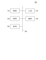
- FIG. 2 is a block diagram illustrating a hardware configuration of the target object detection device. It is a figure showing an example of a divided area. It is a figure showing an example of a divided area.
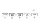
- FIG. 3 is a block diagram illustrating functions of a control unit of the target object detection device.
- FIG. 9 is an explanatory diagram for describing a method of detecting a candidate rectangle based on a feature map.
- FIG. 9 is an explanatory diagram for describing a method of detecting a candidate rectangle based on a feature map.
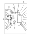
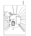
- 9 is an explanatory diagram for describing an example of a candidate rectangle. It is a figure showing an example of an output rectangle outputted as a detection result of a subject. It is explanatory drawing which shows the example of the estimated joint point. 5 is a flowchart illustrating an operation of the target object detection device.
- FIG. 1 is a diagram showing a schematic configuration of a target object detection system including the target object detection device according to the embodiment.
- the target object detection system 10 includes a target object detection device 100, a photographing device 200, a communication network 300, and a mobile terminal 400.
- the target object detection device 100 is communicably connected to the imaging device 200 and the portable terminal 400 via a communication network 300.
- the target object is an object to be detected by the target object detection device 100.
- the target object may include a plurality of categories.
- the category is a type of an object that can be recognized by the target object detection device 100, and includes a person, a bed, a desk, a chair, a walker, and the like.
- the category includes the type of an object other than the target object.
- the target object is the target person 50 (that is, a person).
- the target object detection device 100 receives an image (hereinafter, simply referred to as “captured image 250”) (see FIGS. 2A and 2B) captured by the capture device 200 from the capture device 200 and included in the captured image 250.
- the target person 500 to be detected is detected as a target object.
- the target object detection device 100 detects the target object 500 by detecting a region where the object exists on the captured image 250 and estimating the category of the object included in the detected region.
- the region where the object exists is detected on the captured image 250 as a rectangle including the object (hereinafter, the rectangle is referred to as a “candidate rectangle 253” (see FIG. 7)).
- the target object detection device 100 can further detect the posture and behavior of the target person 500 based on the output rectangle 254. Further, an event related to the subject 500 can be detected from the estimated behavior.
- the event is a change in the state of the target person 70 that is recognized by the target object detection device 100 or the like. For example, an alert (notification) should be issued to the staff 80 such as wake-up, leaving the bed, falling, and abnormal body movement. It is an event.
- the target object detecting device 100 transmits an event notification for notifying the content of the event to the mobile terminal 400.
- the target object detection device 100 can detect the target person 500 by a deep neural network (hereinafter, referred to as “DNN”). Examples of the method of detecting the target object by the DNN include known methods such as Fat @ R-CNN, Fast @ R-CNN, and R-CNN. Hereinafter, the description will be given on the assumption that the target object detection device 100 detects the target object using the Faster @ R-CNN.
- the target object detection device 100 is configured by a computer.
- the target object detection device 100 can be configured as a server.
- the imaging device 200 is configured by, for example, a near-infrared camera, and is installed at a predetermined position, and captures an image of an imaging region viewed from the predetermined position as a viewpoint. That is, the photographing apparatus 200 irradiates near infrared rays toward the photographing area by using an LED (Light Emitting Device), and receives reflected light of the near infrared rays reflected by an object in the photographing area by a CMOS (Complementary Metal Oxide Semiconductor) sensor. By doing so, the photographing area can be photographed.
- the photographed image 250 can be a monochrome image in which the near-infrared reflectance is each pixel.
- the predetermined position is, for example, the ceiling of the room of the subject 500.
- the imaging region is a three-dimensional region including the entire floor of the living room, for example.
- the photographing device 200 can photograph a photographing area as a moving image having a frame rate of, for example, 15 fps to 30 fps.
- the captured image 250 includes a moving image and a still image.
- the imaging device 200 transmits the captured image 250 to the target object detection device 100 and the like.
- the camera constituting the photographing device 200 may be a wide-angle camera.
- the wide-angle camera is a camera that can capture a captured image 250 having a relatively wide angle of view, and is a camera in which the magnitude of distortion changes according to a position on the captured image 250.
- the wide-angle camera includes, for example, a fish-eye lens camera.
- the camera constituting the photographing apparatus 200 has a wide angle of view by adjusting the installation height of the camera and the like (hereinafter, “wide-area photographing camera”) in order to make a relatively wide range the photographing range. ).
- the wide-area photographing camera is a camera that captures a photographed image 250 in which the ratio between the size of an object on the photographed image 250 and the actual size of the object changes according to the distance from the camera to the object in the photographing direction. It is.
- the wide-area photographing camera a general camera in which the magnitude of the distortion is not changed corresponding to the position on the photographed image 250 can be used as the wide-area photographing camera.
- FIG. 2A is an explanatory diagram showing a wide-angle image captured by a wide-angle camera.
- FIG. 2B is an explanatory diagram illustrating a wide-area captured image captured by the wide-area capturing camera.
- FIG. 2A shows a wide-angle image 251 when a person 501 in a living room is photographed by a wide-angle camera.
- the wide-angle image 251 the same person 501 is virtually shown as being photographed in one wide-angle image 251 at three different positions.
- the distortion of the wide-angle image 251 increases from the center of the image toward the outside of the image, as indicated by the dashed arrow.
- the shape or the like changes relatively largely depending on whether the position of the person 501 on the wide-angle image 251 is near or far from the center of the wide-angle image 251.
- FIG. 2B shows a wide-area photographed image 252 obtained by photographing a ship 502 existing on the sea 504 or the sandy beach 505 so as to include the sky 503, the sea 504, and the sandy beach 505 by the wide-area photographing camera.
- the same ship 502 is virtually shown as being photographed in one wide area photographed image 252 at three different positions.
- the distance from the wide-area capturing camera to the boat 502 in the capturing direction increases from the bottom of the image to the top, as indicated by the dashed arrow.
- the size of the ship 502 on the image decreases as the position of the ship 502 on the wide-area captured image 252 moves upward in the wide-area captured image 252.
- the wide-area photographed image 252 corresponds to the change in the distance from the wide-area photographing camera to the object in the photographing direction and the ratio of the size of the object on the image to the actual size of the object (the magnitude of the ratio). Changes).
- the imaging device 200 can be configured by a sensor box having a computer.
- the sensor box is a box-shaped device including a near-infrared camera, a body motion sensor, and the like. In this case, the sensor box may have some or all of the functions of the target object detection device 100.
- the body motion sensor is a Doppler shift type sensor that transmits and receives microwaves to and from the bed and detects Doppler shift of microwaves caused by body motion (for example, respiratory motion) of the subject 500.
- a network interface based on a wired communication standard such as Ethernet (registered trademark) can be used for the communication network 300.
- the communication network 300 may use a network interface based on a wireless communication standard such as Bluetooth (registered trademark) and IEEE 802.11.
- An access point 310 is provided in the communication network 300, and connects the mobile terminal 400 and the target object detection device 100 and the imaging device 200 so as to be able to communicate with each other via a wireless communication network.
- the mobile terminal 400 receives the event notification from the target object detection device 100 and displays the content of the event notification.
- the mobile terminal 400 receives the detection result of the target person 500 detected by the target object detection device 100 from the target object detection device 100, and displays the result.
- the portable terminal 400 can display the detection result of the target person 500 by displaying the output rectangle 254 on the captured image 250.
- the mobile terminal 400 can receive and display the detection result of the posture and the behavior of the target person 500 from the target object detection device 100.
- the posture detection result includes the estimation result of the joint point 119 (see FIG. 9) of the subject 500.
- the detection results of the behavior include detection results of behaviors corresponding to events such as wake-up, leaving the bed, falling, and abnormal body movement, as well as detection results of behaviors such as entering a room, sleeping, and sitting.
- the detection result of the action may be received and included in the event notification.
- the mobile terminal 400 can receive and display the captured image 250 from the imaging device 200 or the target object detection device 100.
- the mobile terminal 400 is configured by, for example, a smartphone.
- FIG. 3 is a block diagram showing a hardware configuration of the target object detection device.
- the target object detection device 100 includes a control unit 110, a storage unit 120, a display unit 130, an input unit 140, and a communication unit 150. These components are interconnected via a bus 160.
- the control unit 110 is configured by a CPU (Central Processing Unit), and performs control and arithmetic processing of each unit of the target object detection device 100 according to a program. Details of the function of the control unit 110 will be described later.
- CPU Central Processing Unit
- the storage unit 120 may be constituted by a RAM (Random Access Memory), a ROM (Read Only Memory), and an SSD (Solid State Drive).
- the RAM temporarily stores programs and data as a work area of the control unit 110.
- the ROM stores various programs and various data in advance.
- the SSD stores various programs including the operation system and various data.
- the storage unit 120 stores region-based estimation parameters in which a divided region (hereinafter, simply referred to as a “divided region”) that divides the captured image 250 into a plurality of regions and a dictionary corresponding to each divided region are set.
- the divided area may be set, for example, as coordinates of pixels included in a plurality of areas of the captured image 250 after division.
- the dictionary is data that defines the weight given between nodes in each layer of the DNN. By reflecting the dictionary on the DNN, the DNN can be used as a learned model.
- a dictionary corresponding to the divided area is reflected on the DNN, and the subject 500 is detected from a feature map (convolution feature map) described later.
- FIGS. 4A and 4B are diagrams showing examples of divided areas.
- FIG. 4A is an example of a divided area set for the wide-angle image 251.
- FIG. 4B is an example of a divided area set for the wide-area captured image 252.
- one rectangular divided region (region indicated by gray E) set at the center of the wide-angle image 251 and eight rectangular divided regions (gray region) set therearound.
- a to D and F to I) That is, the divided area is set so that the wide-angle image 251 is divided into an area where distortion is relatively small and an area where distortion is relatively large.
- a corresponding region-based estimation parameter is used for each divided region.
- different estimation parameters are used for the region of the wide-angle image 251 where the distortion is relatively small and the region where the distortion is relatively large.
- the divided area set in the upper part (area indicated by gray A), the divided area set in the middle part (area indicated by gray B), and the lower part of the wide-area captured image 252 are shown (areas indicated by gray C). That is, the ratio between the size of the object on the wide-area captured image 252 and the actual size of the object is large, the upper portion of the wide-area captured image 252, the lower ratio, and the lower portion of the wide-area captured image 252.
- a divided area is set so as to be divided into a middle part and a middle part of the wide area photographed image 252. Therefore, different region-based estimation parameters are used depending on the ratio of the size of the object on the wide-area captured image 252 to the actual size of the object.
- the display unit 130 is, for example, a liquid crystal display, and displays various information.
- the input unit 140 includes, for example, a touch panel and various keys.
- the input unit 140 is used for various operations and inputs.
- the communication unit 150 is an interface for communicating with an external device.
- a network interface based on standards such as Ethernet (registered trademark), SATA, PCI @ Express, USB, and IEEE1394 can be used.
- a wireless communication interface such as Bluetooth (registered trademark), IEEE 802.11, or 4G may be used for communication.
- the communication unit 150 receives the captured image 250 from the imaging device 200.
- the communication unit 150 transmits the event notification to the mobile terminal 400.
- the communication unit 150 transmits the detection result of the target person 500 from the captured image 250 to the mobile terminal 400.
- communication unit 150 may transmit a detection result of the posture and behavior of target person 500 to portable terminal 400.
- control unit 110 The details of the function of the control unit 110 will be described.
- FIG. 5 is a block diagram illustrating functions of a control unit of the target object detection device.
- the control unit 110 includes an image acquisition unit 111, a target object detection unit 112, a joint point estimation unit 113, a behavior estimation unit 114, and an output unit 115.
- the image acquisition unit 111 constitutes an acquisition unit.
- the target object detection unit 112 configures a feature map generation unit, a detection unit, an object detection unit, and a target object detection unit.
- the image acquisition unit 111 acquires the captured image 250 received from the imaging device 200 via the communication unit 150.
- the target object detection unit 112 detects the target person 500 from the captured image 250 as follows.
- a feature map in which the features of the pixels are extracted is generated by the convolution operation of the captured image 250 by the DNN.
- the estimation parameter for each area is read from the storage unit 120, and for each set division area, the subject 500 is detected from the feature map by the DNN reflecting the dictionary corresponding to the division area.
- a region where the object is present on the captured image 250 is detected as a candidate rectangle 253 based on the feature map by the DNN, and the category of the object included in the candidate rectangle 253 is estimated.
- the candidate rectangle 253 in which the category of the estimated object is a person is detected as the output rectangle 254 including the subject 500.
- a method for detecting the candidate rectangle 253 and the output rectangle 254 from the feature map will be described in detail.
- FIG. 6 is an explanatory diagram for describing a method of detecting a candidate rectangle based on a feature map.
- FIG. 7 is an explanatory diagram for describing an example of a candidate rectangle.
- a portion of the feature map 116 corresponding to the divided area is shown as the feature map 116.
- a grid 117 is set as a local area.
- Each grid 117 is associated with an anchor 118 that is a reference rectangle on the captured image 250.
- Each grid 117 is associated with a plurality of anchors 118 having a predetermined shape. The shape of the plurality of anchors 118 may be different for each divided region.
- the probability that an object exists at each anchor 118 is estimated, and the anchor 118 with the highest probability that the object exists is determined.
- the shift amount of the position and the scale shift amount of the determined anchor 118 from the rectangular area where the object exists are estimated, and the candidate rectangle 253 is detected by minimizing the shift amount.
- candidate rectangles 253 each including an object such as a person, a bed, a desk, a chair, a walker, a television, and a fan are shown. Note that only some of the objects (for example, moving objects such as animals) may be detected as the candidate rectangle 253.
- the target object detection unit 112 calculates a reliability score for each predetermined category for each detected candidate rectangle 253.
- the reliability score is a likelihood for each predetermined category.
- the predetermined category can be arbitrarily set including a person who is a category of the subject 500.
- the predetermined category may be, for example, people, chairs, desks, and equipment.
- the target object detection unit 112 detects, as the output rectangle 254, the candidate rectangle 253 in which the category having the highest reliability score is a person.
- the target object detection unit 112 outputs the detected output rectangle 254 together with the calculated reliability score for each category.
- FIG. 8 is a diagram illustrating an example of an output rectangle 254 output as a result of detection of a target person.
- the detection result of the target person 500 with respect to the wide-angle image 251 is shown.
- An output rectangle 254 output as a detection result is additionally provided with a reliability score for each predetermined category.
- the reliability score of the category of the person is 0.9
- the reliability score of the category of the device is 0.1
- the reliability scores of the other categories are 0.
- the candidate rectangle 253 having the highest reliability score of the category of the person is detected as the output rectangle 254, it can be seen that the subject 500 has been detected.
- the candidate rectangle 253 having the highest reliability score in a category other than “person” is not detected as the output rectangle 254. .
- the subject 500 is detected from the feature map 116 generated from the captured image 250 using a dictionary corresponding to each of the divided regions obtained by dividing the captured image 250.
- a dictionary corresponding to each of the divided regions obtained by dividing the captured image 250 thereby, it is possible to reduce erroneous detection of an object due to a change in the object for each region in the captured image 250.
- the subject 500 is detected from the feature map 116 using the same dictionary in all the regions of the photographed image 250, erroneous detection of the object due to a change in the object for each region in the photographed image 250 Can occur.
- the reliability score of the candidate rectangle 253 including the walker for a person becomes relatively large with respect to other categories, It may happen that the walker is erroneously detected as a person.
- the feature map 116 is generated from the entire captured image 250, and the feature map 116 is not generated for each divided region. That is, one feature map 116 is shared in the detection of the subject 500 from each divided region, and the feature map 116 is not generated for each divided region. Thus, the subject 500 can be detected at high speed and with high accuracy.
- the joint point estimating unit 113 estimates the joint point 119 as the posture of the subject 500 based on the output rectangle 254, and outputs the joint point 119 to the action estimating unit 114 as a detection result of the joint point 119.
- the joint point estimating unit 113 can estimate the joint point 119 based on the output rectangle 254 by a known method using DNN.
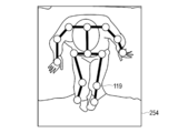
- FIG. 9 is an explanatory diagram showing an example of an estimated joint point.
- the joint point 119 is shown superimposed on the captured image 250, and the position of the joint point 119 is shown by a white circle.
- the joint points 119 include, for example, head, neck, shoulder, elbow, hand, hip, thigh, knee, and foot joint points 119.
- it can be recognized that the subject 500 is in a sitting posture from the relative positional relationship between the joint points 119.
- the behavior estimation unit 114 estimates the behavior of the subject 500 based on the joint points 119 estimated by the joint point estimation unit 113, and outputs the behavior to the output unit 115 as a detection result of the behavior of the subject 500.
- the behavior estimation unit 114 can estimate the behavior of the subject 500 based on a temporal change of the joint point 119 estimated from the plurality of captured images 250. For example, when the average speed of each joint point 119 suddenly decreases and the posture recognized by each joint point 119 after the average speed decreases is in the supine position, the behavior estimation unit 114 determines that the subject 500 "Fallover" can be estimated as the action of the user.
- the output unit 115 outputs the output rectangle 254 detected by the target object detection unit 112, the joint point 119 of the target person 500 detected by the joint point estimation unit 113, and the target rectangle 500 detected by the action estimation unit 114. Output actions.
- the operation of the target object detection device 100 will be described.
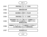
- FIG. 10 is a flowchart showing the operation of the target object detection device. This flowchart is executed by the control unit 110 according to a program stored in the storage unit 120.
- the control unit 110 causes the storage unit 120 to store the region estimation parameters (S101).
- the control unit 110 acquires the captured image 250 from the imaging device 200 via the communication unit 150 (S102).
- the control unit 110 uses the DNN to generate a feature map from the captured image 250 (S103).
- the control unit 110 switches by selecting the area-specific parameters used for the detection of the subject 500.
- the control unit 110 may select a parameter for each area based on distortion characteristics of the wide-angle camera.
- the distortion characteristics of the wide-angle camera are specified by the model number of the wide-angle camera. For this reason, for example, for each wide-angle camera, an area-specific parameter in which a divided area is set corresponding to the distortion characteristic of the wide-angle camera of the model is previously stored in the storage unit 120 in association with the model number of the wide-angle camera. .
- the control unit 110 can select an area-specific parameter corresponding to the model number of the wide-angle camera included in the data of the captured image 250 acquired from the wide-angle camera.
- the control unit 110 displays a screen for accepting the input of the distortion characteristic of the wide-angle camera of the imaging device 200 on the display unit 130, and, based on the distortion characteristic input to the user by the input unit 140, responds to the distortion characteristic.
- a region-specific parameter in which a divided region is set may be selected.
- the control unit 110 may select the parameter for each area based on the installation height of the wide-angle camera of the imaging device 200. For example, for each installation height of the wide-angle camera, an area-specific parameter in which a divided area is set corresponding to the installation height is stored in advance in the storage unit 120 in association with the installation height.
- the CAD Computer-Aided @ Design
- the control unit 110 includes a wide-angle camera installed in the living room based on the CAD data of the facility based on the room data of the room where the wide-angle camera is installed, which is included in the data of the captured image 250 acquired from the wide-angle camera. Calculate the height of the ceiling. Then, an area-specific parameter in which a divided area is set corresponding to the calculated installation height can be acquired.
- the control unit 110 displays a screen for accepting the input of the installation height of the wide-angle camera of the imaging device 200 on the display unit 130, and based on the installation height input by the user in the input unit 140, A region-specific parameter in which a divided region is set correspondingly may be selected.
- the control unit 110 can select a region-specific parameter based on the size of the imaging range of the imaging device 200. For example, for each size of the shooting range of the wide-area shot image 252, an area-specific parameter in which a divided area is set corresponding to the size of the shooting range is previously stored in the storage unit 120 in association with the size of the shooting range.
- the control unit 110 displays on the display unit 130 a screen for accepting an input of the size of the imaging range (for example, the imaging area or the angle of view) of the wide-area imaging camera of the imaging device 200, and inputs the input to the user via the input unit 140.
- the control unit 110 may select the area-specific parameter based on the installation height of the wide-area imaging camera of the imaging apparatus 200. For example, for each installation height of the wide-area photographing camera, an area-specific parameter in which a divided area is set corresponding to the installation height is stored in advance in the storage unit 120 in association with the installation height.
- the CAD data of the facility is stored in the storage unit 120 in advance.
- the control unit 110 determines the wide area in the living room based on the CAD data of the facility from the room number of the room in which the wide area shooting camera is installed, which is included in the data of the wide area shooting image 252 acquired from the wide area shooting camera. Calculate the height of the ceiling where the camera is installed. Then, an area-specific parameter in which a divided area is set corresponding to the calculated installation height can be acquired.
- the control unit 110 displays a screen for accepting the input of the installation height of the wide-area imaging camera of the imaging device 200 on the display unit 130, and based on the installation height input by the user at the input unit 140, the installation height. A parameter for each area in which a divided area is set may be selected correspondingly.
- the control unit 110 detects the candidate rectangle 253 including the object from the feature map using the dictionary corresponding to the divided region for each divided region based on the estimated parameters for each region (S105).
- the control unit 110 calculates the reliability score for each predetermined category for each candidate rectangle 253, and detects the output rectangle 254, thereby detecting the subject 500 (S106).
- the control unit 110 outputs the output rectangle 254 and the reliability score of the output rectangle 254 for each predetermined category to the portable terminal 400 by transmitting the rectangle to the portable terminal 400 (S107).
- a target object is detected from a feature map generated from the captured image using a dictionary corresponding to each divided region.
- the divided area is set according to the magnitude of the distortion that changes in accordance with the position on the captured image that is a wide-angle image.
- the captured image is an image in which the ratio between the size of the object on the captured image and the actual size of the object is changed in accordance with the distance from the camera that captured the captured image to the object in the capturing direction
- the divided area is set according to the ratio of the size of the object on the captured image to the actual size of the object.
- a target object is detected by calculating a reliability score for each predetermined category of the object using a dictionary corresponding to the divided region for each divided region. This makes it possible to calculate the reliability score using the dictionary corresponding to the divided region for each divided region and detect the target object, thereby erroneously detecting the target object due to a change in the target object for each region in the captured image. Can be reduced more effectively, and the target object can be detected at higher speed and with higher accuracy.
- an object is detected from the feature map using a dictionary corresponding to the divided region, and then a reliability score of each of the detected objects for each predetermined category is calculated.
- the target object is detected from the objects. Accordingly, the object detection accuracy and the accuracy of calculating the reliability score for each category of the object can be verified separately, so that the target object can be detected with higher accuracy.
- the shift amount of the position and the shift amount of the scale of the reference rectangle set in the captured image from the rectangular area where the object exists are estimated using the feature map and the dictionary, and the shift amount of the position is determined.
- the candidate rectangle 253 is detected by minimizing the shift amount and the shift amount of the scale.
- a reliability score for each predetermined category of the object included in the candidate rectangle 253 is calculated, and the candidate rectangle in which the category with the highest reliability score is the target object category is output to the output rectangle including the target object.
- the target object is detected by estimating.
- the reference rectangle has a different shape for each divided area. As a result, it is possible to more simply, quickly, and accurately detect a target object using the Faster @ R-CNN.
- the region-based estimation parameters used for detecting the target object are changed according to the region in which the divided region is set corresponding to the lens distortion characteristics. Switch to estimated parameters. Accordingly, the target object can be detected from the wide-angle image at high speed and with high accuracy by a simpler procedure.
- the estimation parameter for each area used to detect the target object is estimated based on the area where the divided area corresponding to the installation height of the camera is set. Switch to parameters. Accordingly, the target object can be detected from the wide-angle image at high speed and with high accuracy by a simpler procedure.
- the region-based estimation parameter used for detecting the target object is switched to the region-based estimation parameter in which a divided region corresponding to the size of the shooting range is set. .
- the target object can be detected from the wide-area captured image at high speed and with high accuracy by a simpler procedure.
- the configuration of the target object detection system 10 described above describes the main configuration in describing the features of the above-described embodiment, and is not limited to the above-described configuration, and may be variously modified within the scope of the claims. Can be. Also, this does not exclude a configuration provided in a general target object detection system.
- the function of the target object detection device 100 may be provided in the imaging device 200 configured by the sensor box or the mobile terminal 400.
- the target object detection device 100, the imaging device 200, and the mobile terminal 400 may each be configured by a plurality of devices, or any one of the plurality of devices may be configured as a single device.
- steps may be omitted from the flowchart described above, and other steps may be added. Further, some of the steps may be executed simultaneously, or one step may be divided into a plurality of steps and executed.
- the target object is not limited to a person but may be a ship, a cat, a dog, or the like, and the target object may include a plurality of categories.
- the means and method for performing various processes in the target object detection system 10 described above can be realized by either a dedicated hardware circuit or a programmed computer.
- the program may be provided by a computer-readable recording medium such as a USB memory or a DVD (Digital Versatile Disc) -ROM, or may be provided online via a network such as the Internet.
- the program recorded on the computer-readable recording medium is usually transferred and stored in a storage unit such as a hard disk.
- the above program may be provided as independent application software, or may be incorporated as one function into software of a device such as a detection unit.
Landscapes
- Engineering & Computer Science (AREA)
- Theoretical Computer Science (AREA)
- Physics & Mathematics (AREA)
- General Physics & Mathematics (AREA)
- Multimedia (AREA)
- Computer Vision & Pattern Recognition (AREA)
- General Health & Medical Sciences (AREA)
- Evolutionary Computation (AREA)
- Health & Medical Sciences (AREA)
- Artificial Intelligence (AREA)
- Human Computer Interaction (AREA)
- Software Systems (AREA)
- Molecular Biology (AREA)
- Computing Systems (AREA)
- Biomedical Technology (AREA)
- Life Sciences & Earth Sciences (AREA)
- Medical Informatics (AREA)
- Social Psychology (AREA)
- Biodiversity & Conservation Biology (AREA)
- Databases & Information Systems (AREA)
- Psychiatry (AREA)
- Biophysics (AREA)
- Computational Linguistics (AREA)
- Data Mining & Analysis (AREA)
- General Engineering & Computer Science (AREA)
- Mathematical Physics (AREA)
- Image Analysis (AREA)
Abstract
Description
Claims (18)
- 撮影された画像を取得する手順(a)と、
前記手順(a)により取得された前記画像から特徴マップを生成する手順(b)と、
前記画像を複数の領域に分割する分割領域と、各分割領域に対応して対象物体を検出するための辞書と、が設定された領域別推定パラメーターに基づいて、前記分割領域ごとに、前記分割領域に対応する前記辞書を用いて、前記特徴マップから、対象物体を検出する手順(c)と、
を有する処理をコンピューターに実行させるための対象物体検出プログラム。 - 前記画像は広角画像であり、
前記分割領域は、前記画像上の位置に対応して変化する歪みの大きさに応じて設定された、請求項1に記載の対象物体検出プログラム。 - 前記画像は、前記画像を撮影したカメラからの撮影方向の物体までの距離に対応して、前記画像上の前記物体の大きさと当該物体の実際の大きさとの比が変化した画像であり、
前記分割領域は、前記比の大きさに応じて設定された、請求項1に記載の対象物体検出プログラム。 - 前記手順(c)は、前記領域別推定パラメーターに基づいて、前記分割領域ごとに、前記分割領域に対応する前記辞書を用いて、物体の所定のカテゴリーごとの信頼度スコアを算出することで、前記対象物体を検出する、請求項1~3のいずれか一項に記載の対象物体検出プログラム。
- 前記手順(c)は、前記領域別推定パラメーターに基づいて、前記分割領域ごとに、前記分割領域に対応する前記辞書を用いて、前記特徴マップから物体を検出する手順(c1)と、前記手順(c1)により検出された前記物体の所定のカテゴリーごとの信頼度スコアを算出することで、前記物体の中から前記対象物体を検出する手順(c2)と、を含む、請求項1~3のいずれか一項に記載の対象物体検出プログラム。
- 前記手順(c)は、前記分割領域ごとに、前記特徴マップと前記辞書とを用いて、前記画像において設定した基準矩形の、物体が存在する矩形領域からの位置のシフト量およびスケールのシフト量を推定して、前記位置のシフト量およびスケールのシフト量を最小化することで前記物体が含まれる候補矩形を検出し、前記候補矩形に含まれた前記物体の所定のカテゴリーごとの信頼度スコアを算出し、前記信頼度スコアが最も高いカテゴリーが前記対象物体のカテゴリーとなった前記候補矩形を、前記対象物体が含まれる出力矩形として出力することで、前記対象物体を検出し、
前記基準矩形の形状は、前記分割領域ごとに異なる、請求項1~3のいずれか一項に記載の対象物体検出プログラム。 - 前記手順(c)は、前記広角画像を撮影したカメラのレンズの歪み特性に基づいて、前記対象物体を検出するために用いる前記領域別推定パラメーターを、当該レンズの歪み特性に対応して前記分割領域が設定された前記領域別推定パラメーターに切り替える、請求項2に記載の対象物体検出プログラム。
- 前記手順(c)は、前記広角画像を撮影したカメラの設置高さに基づいて、前記対象物体を検出するために用いる前記領域別推定パラメーターを、当該カメラの設置高さに対応した前記分割領域が設定された前記領域別推定パラメーターに切り替える、請求項2に記載の対象物体検出プログラム。
- 前記手順(c)は、前記画像の撮影範囲の広さに基づいて、前記対象物体を検出するために用いる前記領域別推定パラメーターを、当該撮影範囲の広さに対応した前記分割領域が設定された前記領域別推定パラメーターに切り替える、請求項3に記載の対象物体検出プログラム。
- 撮影された画像を取得する取得部と、
取得された前記画像から特徴マップを生成する特徴マップ生成部と、
前記画像を複数の領域に分割する分割領域と、各分割領域に対応して対象物体を検出するための辞書と、が設定された領域別推定パラメーターに基づいて、前記分割領域ごとに、前記分割領域に対応する前記辞書を用いて、前記特徴マップから、対象物体を検出する検出部と、
を有する対象物体検出装置。 - 前記画像は広角画像であり、
前記分割領域は、前記画像上の位置に対応して変化する歪みの大きさに応じて設定された、請求項10に記載の対象物体検出装置。 - 前記画像は、前記画像を撮影したカメラからの撮影方向の物体までの距離に対応して、前記画像上の前記物体の大きさと当該物体の実際の大きさとの比が変化した画像であり、
前記分割領域は、前記比の大きさに応じて設定された、請求項10に記載の対象物体検出装置。 - 前記検出部は、前記領域別推定パラメーターに基づいて、前記分割領域ごとに、前記分割領域に対応する前記辞書を用いて、物体の所定のカテゴリーごとの信頼度スコアを算出することで、前記対象物体を検出する、請求項10~12のいずれか一項に記載の対象物体検出装置。
- 前記検出部は、前記領域別推定パラメーターに基づいて、前記分割領域ごとに、前記分割領域に対応する前記辞書を用いて、前記特徴マップから物体を検出する物体検出部と、前記物体検出部により検出された前記物体の所定のカテゴリーごとの信頼度スコアを算出することで、前記物体の中から前記対象物体を検出する対象物体検出部と、を含む、請求項10~12のいずれか一項に記載の対象物体検出装置。
- 前記検出部は、前記分割領域ごとに、前記特徴マップと前記辞書とを用いて、前記画像において設定した基準矩形の、物体が存在する矩形領域からの位置のシフト量およびスケールのシフト量を推定して、前記位置のシフト量およびスケールのシフト量を最小化することで前記物体が含まれる候補矩形を検出し、前記候補矩形に含まれた前記物体の所定のカテゴリーごとの信頼度スコアを算出し、前記信頼度スコアが最も高いカテゴリーが前記対象物体のカテゴリーとなった前記候補矩形を、前記対象物体が含まれる出力矩形として出力することで、前記対象物体を検出し、
前記基準矩形の形状は、前記分割領域ごとに異なる、請求項10~12のいずれか一項に記載の対象物体検出装置。 - 前記検出部は、前記広角画像を撮影したカメラのレンズの歪み特性に基づいて、前記対象物体を検出するために用いる前記領域別推定パラメーターを、当該レンズの歪み特性に対応して前記分割領域が設定された前記領域別推定パラメーターに切り替える、請求項11に記載の対象物体検出装置。
- 前記検出部は、前記広角画像を撮影したカメラの設置高さに基づいて、前記対象物体を検出するために用いる前記領域別推定パラメーターを、当該カメラの設置高さに対応した前記分割領域が設定された前記領域別推定パラメーターに切り替える、請求項11に記載の対象物体検出装置。
- 前記検出部は、前記画像の撮影範囲の広さに基づいて、前記対象物体を検出するために用いる前記領域別推定パラメーターを、当該撮影範囲の広さに対応した前記分割領域が設定された前記領域別推定パラメーターに切り替える、請求項12に記載の対象物体検出装置。
Priority Applications (2)
| Application Number | Priority Date | Filing Date | Title |
|---|---|---|---|
| JP2020528701A JP7243725B2 (ja) | 2018-07-02 | 2019-05-09 | 対象物体検出プログラム、および対象物体検出装置 |
| EP19830090.7A EP3819864A4 (en) | 2018-07-02 | 2019-05-09 | TARGET OBJECT DETECTION PROGRAM AND TARGET OBJECT DETECTION DEVICE |
Applications Claiming Priority (2)
| Application Number | Priority Date | Filing Date | Title |
|---|---|---|---|
| JP2018-126305 | 2018-07-02 | ||
| JP2018126305 | 2018-07-02 |
Publications (1)
| Publication Number | Publication Date |
|---|---|
| WO2020008726A1 true WO2020008726A1 (ja) | 2020-01-09 |
Family
ID=69060638
Family Applications (1)
| Application Number | Title | Priority Date | Filing Date |
|---|---|---|---|
| PCT/JP2019/018629 Ceased WO2020008726A1 (ja) | 2018-07-02 | 2019-05-09 | 対象物体検出プログラム、および対象物体検出装置 |
Country Status (3)
| Country | Link |
|---|---|
| EP (1) | EP3819864A4 (ja) |
| JP (1) | JP7243725B2 (ja) |
| WO (1) | WO2020008726A1 (ja) |
Cited By (2)
| Publication number | Priority date | Publication date | Assignee | Title |
|---|---|---|---|---|
| WO2023181277A1 (ja) * | 2022-03-24 | 2023-09-28 | ファナック株式会社 | 外観検査装置、外観検査方法、及びコンピュータ読み取り可能な記録媒体 |
| JP7365729B1 (ja) | 2022-10-06 | 2023-10-20 | 株式会社アジラ | 姿勢推定システム |
Citations (5)
| Publication number | Priority date | Publication date | Assignee | Title |
|---|---|---|---|---|
| JP2012230546A (ja) | 2011-04-26 | 2012-11-22 | Hitachi Information & Communication Engineering Ltd | 物体認識方法及び認識装置 |
| JP2013141876A (ja) * | 2012-01-10 | 2013-07-22 | Denso Corp | 車両周辺監視装置 |
| JP2016171526A (ja) * | 2015-03-13 | 2016-09-23 | 株式会社東芝 | 画像センサ、人検出方法、制御システム、制御方法及びコンピュータプログラム |
| US20170206431A1 (en) | 2016-01-20 | 2017-07-20 | Microsoft Technology Licensing, Llc | Object detection and classification in images |
| JP2018126305A (ja) | 2017-02-08 | 2018-08-16 | 株式会社オリンピア | 遊技機 |
-
2019
- 2019-05-09 EP EP19830090.7A patent/EP3819864A4/en active Pending
- 2019-05-09 JP JP2020528701A patent/JP7243725B2/ja active Active
- 2019-05-09 WO PCT/JP2019/018629 patent/WO2020008726A1/ja not_active Ceased
Patent Citations (5)
| Publication number | Priority date | Publication date | Assignee | Title |
|---|---|---|---|---|
| JP2012230546A (ja) | 2011-04-26 | 2012-11-22 | Hitachi Information & Communication Engineering Ltd | 物体認識方法及び認識装置 |
| JP2013141876A (ja) * | 2012-01-10 | 2013-07-22 | Denso Corp | 車両周辺監視装置 |
| JP2016171526A (ja) * | 2015-03-13 | 2016-09-23 | 株式会社東芝 | 画像センサ、人検出方法、制御システム、制御方法及びコンピュータプログラム |
| US20170206431A1 (en) | 2016-01-20 | 2017-07-20 | Microsoft Technology Licensing, Llc | Object detection and classification in images |
| JP2018126305A (ja) | 2017-02-08 | 2018-08-16 | 株式会社オリンピア | 遊技機 |
Non-Patent Citations (2)
| Title |
|---|
| MIKI, DAISUKE ET AL.: "Robust Human Pose Estimation from Distorted Images", IEICE TECHNICAL REPORT, vol. 117, no. 238, 5 October 2017 (2017-10-05), pages 169 - 174, XP55672503, ISSN: 0913-5685 * |
| See also references of EP3819864A4 |
Cited By (5)
| Publication number | Priority date | Publication date | Assignee | Title |
|---|---|---|---|---|
| WO2023181277A1 (ja) * | 2022-03-24 | 2023-09-28 | ファナック株式会社 | 外観検査装置、外観検査方法、及びコンピュータ読み取り可能な記録媒体 |
| JPWO2023181277A1 (ja) * | 2022-03-24 | 2023-09-28 | ||
| JP7701553B2 (ja) | 2022-03-24 | 2025-07-01 | ファナック株式会社 | 外観検査装置、外観検査方法、及びコンピュータ読み取り可能な記録媒体 |
| JP7365729B1 (ja) | 2022-10-06 | 2023-10-20 | 株式会社アジラ | 姿勢推定システム |
| JP2024054909A (ja) * | 2022-10-06 | 2024-04-18 | 株式会社アジラ | 姿勢推定システム |
Also Published As
| Publication number | Publication date |
|---|---|
| EP3819864A1 (en) | 2021-05-12 |
| JPWO2020008726A1 (ja) | 2021-07-08 |
| JP7243725B2 (ja) | 2023-03-22 |
| EP3819864A4 (en) | 2021-08-18 |
Similar Documents
| Publication | Publication Date | Title |
|---|---|---|
| JP6137425B2 (ja) | 画像処理システム、画像処理装置、画像処理方法、および画像処理プログラム | |
| JP2020123239A (ja) | 姿勢推定装置、行動推定装置、姿勢推定プログラム、および姿勢推定方法 | |
| US10762761B2 (en) | Monitoring assistance system, control method thereof, and program | |
| CN105938540B (zh) | 行为检测方法和行为检测设备 | |
| JP6115692B1 (ja) | 行動検知装置、該方法および該プログラム、ならびに、被監視者監視装置 | |
| JP7403132B2 (ja) | 介護記録装置、介護記録システム、介護記録プログラムおよび介護記録方法 | |
| JP2022165483A (ja) | 検出装置、検出システム、検出方法、および検出プログラム | |
| JP6086468B2 (ja) | 被写体見守りシステム | |
| JP2020086819A (ja) | 画像処理プログラムおよび画像処理装置 | |
| JP7530222B2 (ja) | 検知装置、検知方法、画像処理方法、およびプログラム | |
| JPWO2016199504A1 (ja) | 行動検知装置および行動検知方法ならびに被監視者監視装置 | |
| US12445720B2 (en) | Device and method for controlling a camera | |
| JP7314939B2 (ja) | 画像認識プログラム、画像認識装置、学習プログラム、および学習装置 | |
| JP7243725B2 (ja) | 対象物体検出プログラム、および対象物体検出装置 | |
| JP7347577B2 (ja) | 画像処理システム、画像処理プログラム、および画像処理方法 | |
| JP6870514B2 (ja) | 見守り支援システム及びその制御方法 | |
| JPWO2019193899A1 (ja) | 演算装置の学習方法、学習装置、学習プログラム、および学習済みモデル | |
| JP2021033379A (ja) | 画像処理システム、画像処理プログラム、および画像処理方法 | |
| JP7786061B2 (ja) | 制御装置、制御方法、制御プログラム、および情報処理システム | |
| JP7351339B2 (ja) | 画像処理システム、画像処理プログラム、および画像処理方法 | |
| JP7435609B2 (ja) | 画像処理システム、画像処理プログラム、および画像処理方法 | |
| JP7606819B2 (ja) | 画像処理システム及び制御プログラム | |
| JP2021065617A (ja) | 画像処理装置および画像処理プログラム | |
| JP7388440B2 (ja) | 画像処理システム、画像処理プログラム、および画像処理方法 | |
| JP2024162612A (ja) | 見守り装置、および見守りシステム |
Legal Events
| Date | Code | Title | Description |
|---|---|---|---|
| 121 | Ep: the epo has been informed by wipo that ep was designated in this application |
Ref document number: 19830090 Country of ref document: EP Kind code of ref document: A1 |
|
| ENP | Entry into the national phase |
Ref document number: 2020528701 Country of ref document: JP Kind code of ref document: A |
|
| NENP | Non-entry into the national phase |
Ref country code: DE |
|
| ENP | Entry into the national phase |
Ref document number: 2019830090 Country of ref document: EP Effective date: 20210202 |
|
| WWW | Wipo information: withdrawn in national office |
Ref document number: 2019830090 Country of ref document: EP |