WO2020008743A1 - 音響波診断装置および音響波診断装置の制御方法 - Google Patents
音響波診断装置および音響波診断装置の制御方法 Download PDFInfo
- Publication number
- WO2020008743A1 WO2020008743A1 PCT/JP2019/020018 JP2019020018W WO2020008743A1 WO 2020008743 A1 WO2020008743 A1 WO 2020008743A1 JP 2019020018 W JP2019020018 W JP 2019020018W WO 2020008743 A1 WO2020008743 A1 WO 2020008743A1
- Authority
- WO
- WIPO (PCT)
- Prior art keywords
- measurement
- unit
- acoustic wave
- recognition
- target
- Prior art date
- Legal status (The legal status is an assumption and is not a legal conclusion. Google has not performed a legal analysis and makes no representation as to the accuracy of the status listed.)
- Ceased
Links
Images


Classifications
-
- A—HUMAN NECESSITIES
- A61—MEDICAL OR VETERINARY SCIENCE; HYGIENE
- A61B—DIAGNOSIS; SURGERY; IDENTIFICATION
- A61B8/00—Diagnosis using ultrasonic, sonic or infrasonic waves
- A61B8/08—Clinical applications
-
- A—HUMAN NECESSITIES
- A61—MEDICAL OR VETERINARY SCIENCE; HYGIENE
- A61B—DIAGNOSIS; SURGERY; IDENTIFICATION
- A61B5/00—Measuring for diagnostic purposes; Identification of persons
- A61B5/0093—Detecting, measuring or recording by applying one single type of energy and measuring its conversion into another type of energy
- A61B5/0095—Detecting, measuring or recording by applying one single type of energy and measuring its conversion into another type of energy by applying light and detecting acoustic waves, i.e. photoacoustic measurements
-
- A—HUMAN NECESSITIES
- A61—MEDICAL OR VETERINARY SCIENCE; HYGIENE
- A61B—DIAGNOSIS; SURGERY; IDENTIFICATION
- A61B8/00—Diagnosis using ultrasonic, sonic or infrasonic waves
- A61B8/46—Ultrasonic, sonic or infrasonic diagnostic devices with special arrangements for interfacing with the operator or the patient
- A61B8/461—Displaying means of special interest
- A61B8/463—Displaying means of special interest characterised by displaying multiple images or images and diagnostic data on one display
-
- A—HUMAN NECESSITIES
- A61—MEDICAL OR VETERINARY SCIENCE; HYGIENE
- A61B—DIAGNOSIS; SURGERY; IDENTIFICATION
- A61B8/00—Diagnosis using ultrasonic, sonic or infrasonic waves
- A61B8/46—Ultrasonic, sonic or infrasonic diagnostic devices with special arrangements for interfacing with the operator or the patient
- A61B8/461—Displaying means of special interest
- A61B8/465—Displaying means of special interest adapted to display user selection data, e.g. icons or menus
-
- A—HUMAN NECESSITIES
- A61—MEDICAL OR VETERINARY SCIENCE; HYGIENE
- A61B—DIAGNOSIS; SURGERY; IDENTIFICATION
- A61B8/00—Diagnosis using ultrasonic, sonic or infrasonic waves
- A61B8/46—Ultrasonic, sonic or infrasonic diagnostic devices with special arrangements for interfacing with the operator or the patient
- A61B8/467—Ultrasonic, sonic or infrasonic diagnostic devices with special arrangements for interfacing with the operator or the patient characterised by special input means
- A61B8/469—Ultrasonic, sonic or infrasonic diagnostic devices with special arrangements for interfacing with the operator or the patient characterised by special input means for selection of a region of interest
-
- A—HUMAN NECESSITIES
- A61—MEDICAL OR VETERINARY SCIENCE; HYGIENE
- A61B—DIAGNOSIS; SURGERY; IDENTIFICATION
- A61B8/00—Diagnosis using ultrasonic, sonic or infrasonic waves
- A61B8/52—Devices using data or image processing specially adapted for diagnosis using ultrasonic, sonic or infrasonic waves
- A61B8/5207—Devices using data or image processing specially adapted for diagnosis using ultrasonic, sonic or infrasonic waves involving processing of raw data to produce diagnostic data, e.g. for generating an image
-
- A—HUMAN NECESSITIES
- A61—MEDICAL OR VETERINARY SCIENCE; HYGIENE
- A61B—DIAGNOSIS; SURGERY; IDENTIFICATION
- A61B8/00—Diagnosis using ultrasonic, sonic or infrasonic waves
- A61B8/52—Devices using data or image processing specially adapted for diagnosis using ultrasonic, sonic or infrasonic waves
- A61B8/5215—Devices using data or image processing specially adapted for diagnosis using ultrasonic, sonic or infrasonic waves involving processing of medical diagnostic data
- A61B8/5223—Devices using data or image processing specially adapted for diagnosis using ultrasonic, sonic or infrasonic waves involving processing of medical diagnostic data for extracting a diagnostic or physiological parameter from medical diagnostic data
-
- A—HUMAN NECESSITIES
- A61—MEDICAL OR VETERINARY SCIENCE; HYGIENE
- A61B—DIAGNOSIS; SURGERY; IDENTIFICATION
- A61B8/00—Diagnosis using ultrasonic, sonic or infrasonic waves
- A61B8/54—Control of the diagnostic device
-
- G—PHYSICS
- G06—COMPUTING OR CALCULATING; COUNTING
- G06F—ELECTRIC DIGITAL DATA PROCESSING
- G06F3/00—Input arrangements for transferring data to be processed into a form capable of being handled by the computer; Output arrangements for transferring data from processing unit to output unit, e.g. interface arrangements
- G06F3/01—Input arrangements or combined input and output arrangements for interaction between user and computer
- G06F3/03—Arrangements for converting the position or the displacement of a member into a coded form
- G06F3/041—Digitisers, e.g. for touch screens or touch pads, characterised by the transducing means
-
- G—PHYSICS
- G06—COMPUTING OR CALCULATING; COUNTING
- G06F—ELECTRIC DIGITAL DATA PROCESSING
- G06F3/00—Input arrangements for transferring data to be processed into a form capable of being handled by the computer; Output arrangements for transferring data from processing unit to output unit, e.g. interface arrangements
- G06F3/01—Input arrangements or combined input and output arrangements for interaction between user and computer
- G06F3/048—Interaction techniques based on graphical user interfaces [GUI]
- G06F3/0487—Interaction techniques based on graphical user interfaces [GUI] using specific features provided by the input device, e.g. functions controlled by the rotation of a mouse with dual sensing arrangements, or of the nature of the input device, e.g. tap gestures based on pressure sensed by a digitiser
- G06F3/0488—Interaction techniques based on graphical user interfaces [GUI] using specific features provided by the input device, e.g. functions controlled by the rotation of a mouse with dual sensing arrangements, or of the nature of the input device, e.g. tap gestures based on pressure sensed by a digitiser using a touch-screen or digitiser, e.g. input of commands through traced gestures
-
- G—PHYSICS
- G16—INFORMATION AND COMMUNICATION TECHNOLOGY [ICT] SPECIALLY ADAPTED FOR SPECIFIC APPLICATION FIELDS
- G16H—HEALTHCARE INFORMATICS, i.e. INFORMATION AND COMMUNICATION TECHNOLOGY [ICT] SPECIALLY ADAPTED FOR THE HANDLING OR PROCESSING OF MEDICAL OR HEALTHCARE DATA
- G16H40/00—ICT specially adapted for the management or administration of healthcare resources or facilities; ICT specially adapted for the management or operation of medical equipment or devices
- G16H40/60—ICT specially adapted for the management or administration of healthcare resources or facilities; ICT specially adapted for the management or operation of medical equipment or devices for the operation of medical equipment or devices
- G16H40/63—ICT specially adapted for the management or administration of healthcare resources or facilities; ICT specially adapted for the management or operation of medical equipment or devices for the operation of medical equipment or devices for local operation
-
- G—PHYSICS
- G06—COMPUTING OR CALCULATING; COUNTING
- G06F—ELECTRIC DIGITAL DATA PROCESSING
- G06F2203/00—Indexing scheme relating to G06F3/00 - G06F3/048
- G06F2203/041—Indexing scheme relating to G06F3/041 - G06F3/045
- G06F2203/04105—Pressure sensors for measuring the pressure or force exerted on the touch surface without providing the touch position
Definitions
- the present invention relates to an acoustic wave diagnostic device and a control method of the acoustic wave diagnostic device, and more particularly to an acoustic wave diagnostic device that measures a part on an acoustic wave image and a control method of the acoustic wave diagnostic device.
- a medical acoustic wave diagnostic apparatus generally has a measurement function for measuring length, size, area, and the like of various organs, lesions, and the like included in an acquired acoustic wave image.
- a caliper that is, a cursor using an input device such as a touch pad, a track ball, and a mouse to set coordinates such as a measurement point and a region of interest on a display image. It has been done.
- a caliper that is, a cursor using an input device such as a touch pad, a track ball, and a mouse to set coordinates such as a measurement point and a region of interest on a display image. It has been done.
- the user's experience, skill level, and the like affect the operation, and various attempts have been made to automate the operation.
- Patent Literature 1 when a position of a caliper used for measurement of a measurement target is input from a user via an operation unit on an ultrasonic image, image processing is performed on a region around the input caliper.
- An ultrasonic diagnostic apparatus that corrects the position of the caliper to an appropriate position by performing the operation is disclosed.
- the ultrasonic diagnostic apparatus disclosed in Patent Literature 1 for example, when a user inputs a pair of calipers for measuring a distance between two points on an ultrasonic image, the pair of calipers is placed at an appropriate position. And the length of the measurement target is measured based on the corrected pair of calipers.
- the present invention has been made to solve such a conventional problem, and an object of the present invention is to provide an acoustic wave diagnostic apparatus and a control method of the acoustic wave diagnostic apparatus that can easily perform measurement. .
- an acoustic wave diagnostic apparatus of the present invention includes a display unit that displays an acquired acoustic wave image, an operation unit for a user to perform an input operation, and a display via the operation unit.
- a measurement position designation receiving unit that receives designation of a measurement position on the acoustic wave image displayed on the unit, and a measurement included in the acoustic wave image in a recognition range determined based on the measurement position received by the measurement position designation reception unit
- a measurement object recognition unit that recognizes an object, a measurement algorithm setting unit that sets a measurement algorithm based on the measurement object recognized by the measurement object recognition unit, and an acoustic wave based on the measurement algorithm set by the measurement algorithm setting unit.
- a measurement unit that measures the measurement target on the image and displays the measurement result on the display unit.
- the recognition range is determined by the recognition range determination unit
- the measurement target is recognized by the measurement target recognition unit
- the measurement algorithm is set by the measurement algorithm setting unit
- the measurement by the measurement unit is performed. It is preferable that the display of the measurement results is automatically performed sequentially.
- a measurement execution instruction receiving unit that receives an instruction to start measurement on the measurement target made by the user via the operation unit is provided. When the instruction to start measurement on the measurement target is received by the measurement execution instruction reception unit, recognition is performed.
- the measurement algorithm setting unit sets a measurement algorithm for each of the plurality of measurement targets. , And each measurement result can be displayed on the display unit. At this time, the measurement unit can display the measurement results for the plurality of measurement targets on the display unit in association with the plurality of measurement targets on the acoustic wave image.
- the measurement order determination unit determines a measurement order of the plurality of measurement targets. According to the determined measurement order, a measurement algorithm is set for a plurality of measurement objects sequentially, and the measurement unit sequentially performs measurement from the measurement objects for which the measurement algorithm is set by the measurement algorithm setting unit and displays measurement results for the plurality of measurement objects. Section. At this time, the measurement order determination unit can assign the measurement order to the plurality of measurement targets such that the shorter the distance from the measurement position on the acoustic wave image, the faster the measurement order.
- a measurement target selection reception unit that receives a selection of one of the plurality of measurement targets from the user via the operation unit is provided.
- the measurement algorithm setting unit sets a measurement algorithm based on one measurement target whose selection has been received by the measurement target selection reception unit, and the measurement unit performs measurement on one measurement target based on the measurement algorithm.
- the measurement result can be displayed on the display unit.
- the operation unit includes a touch sensor arranged on the display unit, and the measurement position designation receiving unit receives a position touched by a user's finger on the acoustic wave image displayed on the display unit as a measurement position. be able to.
- the recognition range can have a defined size.
- a recognition range determination unit that sets the size of the recognition range in accordance with a touch operation with the user's finger can be provided.
- the recognition range determination unit can set the size of the recognition range according to the length of time when the measurement position on the acoustic wave image is touched by the user's finger. Further, the recognition range determination unit, when the measurement position on the acoustic wave image is touched by the user's finger and the user's finger is moved on the acoustic wave image, the moving direction of the user's finger on the acoustic wave image and The size of the recognition range can be set according to the moving distance.
- the operation unit includes a pressure sensor disposed on the display unit and the touch sensor, and the recognition range determination unit determines the size of the recognition range according to the magnitude of the pressure of the user's finger detected by the pressure sensor. Can also be set.
- the control method of the acoustic wave diagnostic apparatus of the present invention displays the acquired acoustic wave image, accepts designation of a measurement position on the acoustic wave image by the user, and recognizes the acoustic wave image based on the accepted measurement position. Determine the range, recognize the measurement target included in the determined recognition range, set the measurement algorithm based on the recognized measurement target, and measure the measurement target from the acoustic wave image based on the set measurement algorithm And displaying a measurement result for the measurement target.
- an acoustic wave diagnostic apparatus includes an operation unit for a user to perform an input operation, and a measurement for receiving a designation of a measurement position on an acoustic wave image displayed on a display unit from the user via the operation unit.
- a position specification receiving unit a recognition range determining unit that determines a recognition range on the acoustic wave image based on the measurement position received by the measurement position specification receiving unit, and an acoustic wave image of the recognition range determined by the recognition range determining unit
- the measurement algorithm set by the measurement algorithm recognition unit which sets the measurement algorithm based on the measurement object recognized by the measurement object recognition unit, and the measurement algorithm set by the measurement algorithm recognition unit
- Measurement unit that measures the measurement target on the acoustic wave image and displays the measurement result on the display unit.
- FIG. 1 is a block diagram illustrating a configuration of an ultrasonic diagnostic apparatus according to Embodiment 1 of the present invention.
- FIG. 3 is a block diagram illustrating an internal configuration of an image generation unit according to Embodiment 1 of the present invention.
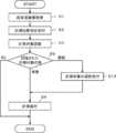
- 5 is a flowchart illustrating an operation of the ultrasonic diagnostic apparatus according to Embodiment 1 of the present invention.
- FIG. 3 is a diagram illustrating an example of a recognition range according to the first embodiment of the present invention.
- 5 is a flowchart illustrating a measurement operation according to the first embodiment of the present invention.
- FIG. 5 is a diagram illustrating an example of a measurement result according to the first embodiment of the present invention.
- FIG. 1 is a block diagram illustrating a configuration of an ultrasonic diagnostic apparatus according to Embodiment 1 of the present invention.
- FIG. 3 is a block diagram illustrating an internal configuration of an image generation unit according to Embodiment 1 of the present invention.
- 5 is a flowchart illustrating
- FIG. 6 is a block diagram illustrating a configuration of an ultrasonic diagnostic apparatus according to Embodiment 2 of the present invention.
- 9 is a flowchart illustrating an operation of the ultrasonic diagnostic apparatus according to Embodiment 2 of the present invention.
- FIG. 9 is a diagram illustrating a measurement execution button according to Embodiment 2 of the present invention.
- FIG. 9 is a block diagram illustrating a configuration of an ultrasonic diagnostic apparatus according to Embodiment 3 of the present invention.
- 9 is a flowchart illustrating an operation of the ultrasonic diagnostic apparatus according to Embodiment 3 of the present invention.
- FIG. 14 is a diagram illustrating an example of a recognition range according to Embodiment 3 of the present invention.
- FIG. 15 is a diagram illustrating an example of a measurement result in a modification of the third embodiment of the present invention.
- FIG. 14 is a block diagram illustrating a configuration of an ultrasonic diagnostic apparatus according to Embodiment 4 of the present invention.
- 13 is a flowchart illustrating an operation of the ultrasonic diagnostic apparatus according to Embodiment 4 of the present invention.
- FIG. 14 is a diagram illustrating an example of a measurement result list according to Embodiment 4 of the present invention.
- FIG. 21 is a diagram showing an example of a target area line in a modification of the fourth embodiment of the present invention.
- FIG. 13 is a block diagram illustrating a configuration of an ultrasonic diagnostic apparatus according to Embodiment 5 of the present invention.
- FIG. 15 is a flowchart illustrating an operation of the ultrasonic diagnostic apparatus according to Embodiment 5 of the present invention.
- FIG. 21 is a diagram illustrating an example of a recognition range according to Embodiment 5 of the present invention.
- FIG. 21 is a diagram illustrating an example of a recognition range in a modification of the fifth embodiment of the present invention.
- FIG. 21 is a diagram illustrating an example of a recognition range according to another modification of the fifth embodiment of the present invention.
- FIG. 21 is a diagram showing an example of a recognition range in still another modification of the fifth embodiment of the present invention.
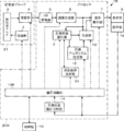
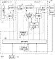
- FIG. 1 shows a configuration of an ultrasonic diagnostic apparatus 1 according to Embodiment 1 of the present invention.
- the ultrasonic diagnostic apparatus 1 includes a vibrator array 2, and a transmitting unit 3 and a receiving unit 4 are connected to the vibrator array 2.
- An AD (Analog Digital) converter 5, an image generator 6, a display controller 7, and a display unit 8 are sequentially connected to the receiving unit 4, and an operation unit 15 is arranged so as to overlap the display unit 8.
- the measurement object recognition unit 9 and the measurement unit 10 are connected to the image generation unit 6, respectively.
- the measurement unit 10 is connected to the measurement object recognition unit 9, and the display control unit 7 is connected to the measurement unit 10. I have.
- the measurement algorithm setting unit 12 is connected to the measurement object recognition unit 9, and the measurement unit 10 is connected to the measurement algorithm setting unit 12.
- a device control unit 13 is connected to the transmission unit 3, the reception unit 4, the image generation unit 6, the display control unit 7, the measurement target recognition unit 9, the measurement unit 10, the measurement algorithm setting unit 12, and the device control unit
- the measurement position designation receiving unit 14, the operation unit 15, and the storage unit 16 are connected to 13.
- an ultrasonic probe 21 is configured by the transducer array 2, the transmission unit 3, and the reception unit 4, and includes an AD conversion unit 5, an image generation unit 6, a display control unit 7, a measurement target recognition unit 9, and a measurement unit 10.
- the processor 22 includes the measurement algorithm setting unit 12, the device control unit 13, and the measurement position designation receiving unit 14.
- the transducer array 2 of the ultrasonic probe 21 shown in FIG. 1 has a plurality of one-dimensional or two-dimensional ultrasonic transducers. These ultrasonic transducers each transmit an ultrasonic wave according to the drive signal supplied from the transmission unit 3, receive a reflected wave from the subject, and output a reception signal.
- Each ultrasonic vibrator is made of, for example, a piezoelectric ceramic represented by PZT (Lead Zirconate Titanate: lead zirconate titanate), a polymer piezoelectric element represented by PVDF (Poly Vinylidene DiDiFluoride: polyvinylidene fluoride), and PMN-.
- the transmitting unit 3 of the ultrasonic probe 21 includes, for example, a plurality of pulse generators, and based on the transmission delay pattern selected according to the control signal from the device control unit 13, the transmitting unit 3 of the transducer array 2
- Each drive signal is supplied to a plurality of ultrasonic transducers by adjusting the amount of delay so that ultrasonic waves transmitted from the ultrasonic transducer form an ultrasonic beam.
- a pulse or continuous wave voltage is applied to the electrodes of the ultrasonic transducers of the transducer array 2
- the piezoelectric body expands and contracts, and the pulse or continuous wave ultrasonic waves are generated from the respective ultrasonic transducers. Is generated, and an ultrasonic beam is formed from a composite wave of the ultrasonic waves.
- the transmitted ultrasonic beam is reflected by a target such as a part of a subject, and propagates toward the transducer array 2 of the ultrasonic probe 21.
- the ultrasonic waves propagating toward the transducer array 2 are received by the respective ultrasonic transducers constituting the transducer array 2.
- each of the ultrasonic vibrators constituting the vibrator array 2 expands and contracts by receiving the propagating ultrasonic echo to generate electric signals, and receives the electric signals as the receiving signals.
- the receiving unit 4 has an amplifying unit for amplifying the received signal input from each ultrasonic transducer, and the signal amplified by the amplifying unit is sent to the AD converting unit 5. .
- the AD converter 5 of the processor 22 converts the received signal sent from the receiver 4 into digitized element data and sends the element data to the image generator 6.
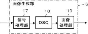
- the image generating unit 6 of the processor 22 has a configuration in which a signal processing unit 17, a DSC (Digital Scan Converter) 18 and an image processing unit 19 are connected in series.
- the signal processing unit 17 gives each element data according to the set sound velocity, based on the reception delay pattern selected according to the control signal from the device control unit 13, and performs addition (phasing addition). Perform reception focus processing. By this reception focus processing, a sound ray signal in which the focus of the ultrasonic echo is narrowed is generated.
- the signal processing unit 17 performs an envelope detection process on the generated sound ray signal after correcting the attenuation due to the propagation distance according to the depth of the position where the ultrasonic wave is reflected, A B-mode image signal, which is tomographic image information on a tissue in the subject, is generated.
- the B-mode image signal generated in this way is output to the DSC 18.
- the DSC 18 raster-converts the B-mode image signal into an image signal according to a normal television signal scanning method, that is, a B-mode image.
- the image processing unit 19 performs various necessary image processing such as brightness correction, gradation correction, sharpness correction, and color correction on the image data obtained by the DSC 18, and then outputs a B-mode image signal to the display control unit. 7. Output to the measurement object recognition unit 9 and the measurement unit 10.
- this B-mode image is simply referred to as an ultrasonic image.
- the display controller 7 of the processor 22 performs a predetermined process on the ultrasonic image generated by the image generator 6 under the control of the device controller 13 and causes the display 8 to display the ultrasonic image. Further, the display control unit 7 causes the display unit 8 to display the measurement result calculated by the measurement unit 10 as described later.
- the display unit 8 of the ultrasonic diagnostic apparatus 1 has a display screen (not shown), and under the control of the display control unit 7, the ultrasonic image generated by the image generation unit 6 and the measurement calculated by the measurement unit 10. The result is displayed on the display screen.
- the display unit 8 includes a display device such as an LCD (Liquid Crystal Display) and an organic EL display (Organic Electroluminescence Display).
- the operation unit 15 of the ultrasonic diagnostic apparatus 1 is used by a user to perform an input operation, and includes a touch sensor that is arranged on the display unit 8.
- the touch sensor is disposed so as to be superimposed on the display screen of the display unit 8, and performs an input operation by a so-called touch operation in which a user's finger, a stylus pen, and the like are brought into contact with or close to the display screen.
- Information input by the user via the touch sensor of the operation unit 15 is transmitted to the device control unit 13 and the measurement position designation reception unit 14.
- the measurement position specification receiving unit 14 of the processor 22 receives the specification of the measurement position on the ultrasonic image displayed on the display unit 8 from the user via the operation unit 15.
- the measurement position is an approximate position of the measurement target included in the ultrasonic image.
- the measurement position specification receiving unit 14 receives the specification of the measurement position by the user.
- the measurement target recognition unit 9 of the processor 22 performs image recognition on the ultrasonic image within the recognition range determined based on the measurement position received by the measurement position specification reception unit 14, and includes the ultrasonic image in the ultrasonic image.
- the recognition range is a range on an ultrasonic image in which the measurement target recognition unit 9 recognizes the measurement target, and includes, for example, the measurement position received by the measurement position specification reception unit 14 and has a predetermined size. It is the range which has the.
- the measurement target may include a site to be measured, such as an organ, and a lesion site such as a tumor, a cyst, and a hemorrhage.
- the measurement target recognition unit 9 can recognize the measurement target in the ultrasonic image using, for example, machine learning such as deep learning.
- machine learning such as deep learning.
- a large amount of typical pattern data for the measurement target is learned as positive data in advance by the measurement target recognition unit 9 and negative pattern data other than typical pattern data for the measurement target is used.
- a large amount of pattern data can be learned in advance to construct a neural network.
- the measurement object recognition unit 9 calculates the length of a characteristic portion of the pattern included in the ultrasonic image, and uses the calculation result and the constructed neural network to calculate these patterns. By classifying the data, the measurement target can be recognized.
- the measurement object recognition unit 9 recognizes the measurement object by assigning the likelihood for the learned pattern data to the pattern included in the ultrasound image and performing a threshold determination on the likelihood.
- the likelihood is a value indicating the likelihood of a pattern included in an ultrasonic image with respect to a plurality of learned pattern data. For example, if the likelihood of a pattern included in the ultrasound image is high with respect to the gallbladder pattern data, the pattern included in the ultrasound image has a high probability of being a gall bladder.
- the method of machine learning is described in, for example, Csurka et al .: Visual Categorization with Bags of Keypoints, Proc. Of ECCV Workshop on Statistical Learning in Computer Vision, pp.59-74 (2004) and the like. Techniques can be used.
- the measurement target recognition unit 9 stores typical pattern data in advance as a template, calculates the similarity to the pattern data while searching for the template in the image. The measurement target can be recognized by considering that the measurement target exists at the new location.
- the measurement algorithm setting unit 12 of the processor 22 sets a measurement algorithm for the measurement target recognized by the measurement target recognition unit 9.
- the measurement algorithm setting unit 12 previously stores measurement algorithms corresponding to a plurality of parts that can be a measurement target as an association table, and sets the measurement algorithm with reference to the association table when the measurement target is determined. .
- the measurement rule is a rule regarding which part and how to measure a specific measurement target.
- the measurement target is the gall bladder
- a measurement rule a line segment having two points on the inner wall of the gall bladder region included in the ultrasound image and passing through the center of gravity of the gall bladder region and having the maximum distance as a measurement line
- the measurement target is a kidney
- a measurement rule is to measure a length between two points at which the distance is maximum among two points on the boundary of the kidney region included in the ultrasound image.
- the measurement algorithm defines a calculation means for executing such a measurement rule, and differs for each measurement target.
- the algorithm is an algorithm that defines a calculation means for achieving a purpose such as measurement.
- the algorithm is implemented in a device as a software program and executed by a CPU (Central Processing Unit). Things.
- a CPU Central Processing Unit
- Things As the measurement algorithm set in the measurement algorithm setting unit 12, a commonly used well-known algorithm can be used.
- the measurement unit 10 of the processor 22 measures the measurement target recognized by the measurement target recognition unit 9 based on the measurement algorithm set by the measurement algorithm setting unit 12, and displays the display unit 8 via the display control unit 7. To display the measurement result.
- the measurement result displayed by the measurement unit 10 on the display unit 8 may include the name of the measurement target, a measurement line used for measurement, a caliper, and the like, in addition to the measurement value for the measurement target.
- the storage unit 16 of the ultrasonic diagnostic apparatus 1 stores an operation program of the ultrasonic diagnostic apparatus 1 and the like, and includes a hard disk drive (HDD), a solid state drive (SSD), and a flexible state drive (FD).
- Disc Flexible disk, MO disk (Magneto-Optical disk: magneto-optical disk), MT (Magnetic Tape: magnetic tape), RAM (Random Access Memory: random access memory), CD (Compact Disc: compact disk), DVD ( A recording medium such as a Digital Versatile Disc: an SD card (Secure Digital Card), a USB memory (Universal Serial Bus memory), a server, or the like can be used.
- the processor 22 including the AD conversion unit 5, the image generation unit 6, the display control unit 7, the measurement target recognition unit 9, the measurement unit 10, the measurement algorithm setting unit 12, the device control unit 13, and the measurement position designation reception unit 14 includes: It is composed of a CPU (Central Processing Unit) and a control program for causing the CPU to perform various kinds of processing.
- An FPGA Field Programmable Gate Array
- DSP Digital Signal Processor: A digital signal processor
- ASIC Application Specific Integrated Circuit
- GPU Graphics Processing Unit
- another IC Integrated Circuit
- the AD conversion unit 5, the image generation unit 6, the display control unit 7, the measurement target recognition unit 9, the measurement unit 10, the measurement algorithm setting unit 12, the device control unit 13, and the measurement position designation reception unit 14 of the processor 22 are partially configured. Alternatively, it may be configured to be integrated into one CPU or the like as a whole.
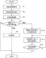
- step S1 at least one ultrasonic image is acquired by the ultrasonic diagnostic apparatus 1, and the acquired one ultrasonic image is displayed on the display unit 8.
- one ultrasonic image displayed on the display unit 8 for example, an ultrasonic image captured on the spot using the ultrasonic probe 21 can be used.
- the user performs an input operation via the operation unit 15. Is performed, one ultrasonic image can be freeze-displayed on the display unit 8.
- an ultrasonic image acquired from an external memory (not shown) can be used as one ultrasonic image displayed on the display unit 8.
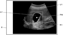
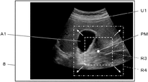
- step S2 as shown in FIG. 4, when the measurement position PM on the ultrasonic image U1 displayed on the display unit 8 is touched and designated by the user, the measurement position designation receiving unit 14 The measurement position PM specified by the user is received. At this time, the user may designate a point located in or near the region representing the measurement target in the ultrasonic image U1 as the measurement position PM.
- the gall bladder A1 is included in the ultrasound image U1, and the measurement position PM is specified on the gall bladder A1 in the ultrasound image U1. In this way, when the designation of the measurement position PM is accepted by the measurement position designation accepting unit 14, the following steps S3 and S4 are automatically executed sequentially by the ultrasonic diagnostic apparatus 1.
- the measurement target recognition unit 9 includes the measurement position PM specified by the user and in the ultrasonic image U1 within the recognition range R1 having a predetermined size. Recognize the measurement target.
- the recognition range R1 is a square range arranged so that the measurement position PM is the center, and includes the gall bladder A1. At this time, the measurement target recognition unit 9 recognizes the gallbladder A1 as a measurement target.
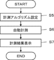
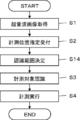
- Step S4 will be described in detail with reference to the flowchart of FIG. Step S4, as shown in FIG. 5, includes three steps of steps S5 to S7.
- step S5 the measurement algorithm setting unit 12 sets a measurement algorithm for the measurement target recognized in step S3.
- the measurement algorithm setting unit 12 sets the maximum to two points arranged on the inner wall of the region representing the gall bladder A1 in the ultrasonic image U1 as the end points.
- a line segment of the distance is determined as a measurement line, and a measurement algorithm for measuring the length of the measurement line is set.
- the measurement line ML1 having the calipers C1A and C1B as end points and the measurement line ML1 perpendicular to the measurement line ML1 and the caliper C2A are set so that the distance between the inner walls of the gallbladder A1 is maximized in two directions orthogonal to each other.
- C2B are set as the end points.
- the measurement algorithm setting unit 12 sets a measurement algorithm according to the measurement target recognized in step S3. At this time, the measurement algorithm setting unit 12 can set a measurement algorithm for measuring the area in addition to the measurement algorithm for measuring the length, for example, according to the measurement target. It is also possible to set a measurement algorithm to be performed.
- the measurement unit 10 performs automatic measurement on the measurement target based on the measurement algorithm set in step S5.
- the measurement unit 10 displays the measurement result on the display unit 8 in step S7.
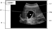
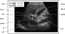
- the measurement unit 10 measures the measurement line ML1 having the calipers C1A and C1B as end points, the measurement line ML2 having the calipers C2A and C2B as end points, the name of the measurement target, and the measurement result, as shown in FIG.
- the measurement result panel PR representing the value can be displayed so as to be superimposed on the ultrasonic image U1.
- step S5 shows that the length of the measurement line ML1, that is, the length of the gallbladder A1 in the long axis direction is 5.6 cm, and that the length of the measurement line ML2, that is, the length of the gall bladder A1 in the short axis direction. Is shown to be 3.1 cm.
- the measurement position PM that is the approximate position of the measurement target included in the ultrasonic image U1 displayed on the display unit 8 is specified by the user, and the measurement position
- the specification of the measurement position PM is received by the specification receiving unit 14
- a series of operations including recognition of the measurement target within the recognition range R1, setting of the measurement algorithm, measurement of the measurement target, and display of the measurement result are automatically performed. Therefore, measurement can be easily performed.
- the measurement target recognition unit 9 includes the measurement position PM received by the measurement position designation reception unit 14 and is within the recognition range R1 having a predetermined size. Since the measurement target is recognized only in, the calculation load required for the recognition of the measurement target can be reduced, and the measurement target can be quickly recognized.
- the measurement target is included in the recognition range R1
- the measurement target may not be included in the recognition range R1.
- the measurement target recognition unit 9 cannot recognize the measurement target within the recognition range R1 in step S3, for example, the operation of the ultrasonic diagnostic apparatus 1 is performed without performing the automatic measurement in step S4. Can be finished. At this time, a message indicating that the measurement target cannot be found can be displayed on the display unit 8.
- the measurement algorithm setting unit 12 automatically sets the measurement algorithm according to the measurement target recognized in step S3, but sets the measurement algorithm to be set in advance according to the user's preference or the like. I can put it.
- a first length that measures both the length in the long axis direction, ie, the length of the measurement line ML1, and the length in the short axis direction, ie, the length of the measurement line ML2.
- a measurement algorithm, a second measurement algorithm that measures only the length of the measurement line ML1 in the long axis direction, and a third measurement algorithm that measures only the length of the measurement line ML2 in the short axis direction are prepared.
- the measurement algorithm for the gallbladder A1 can be set to one that suits the user's preference.
- the measurement unit 10 calculates a plurality of measurement values, a corresponding plurality of measurement target names, and a corresponding plurality of measurement lines. And a plurality of corresponding calipers and the like can be displayed in different modes for each measurement value.
- the measurement unit 10 displays at least one of the color, thickness, type of line such as a solid line and a dashed line, and transmittance of each item related to each measurement value on the display unit 8 with different measurement values. can do.
- the recognition range R1 having a square is illustrated, but the shape of the recognition range R1 is not limited to a square.
- the recognition range R1 may be rectangular, circular, or polygonal, and may have any shape as long as it is a closed range.
- Embodiment 2 In the first embodiment, when the ultrasonic image U1 displayed on the display unit 8 is touched by the user to specify the measurement position PM, the measurement position specification receiving unit 14 receives the specification of the measurement position PM, and performs recognition. A series of operations including the determination of the range R1, the recognition of the measurement target, the setting of the measurement algorithm, the measurement of the measurement target, and the display of the measurement result are automatically performed. The instruction from the user via the operation unit 15 is used as a trigger. , A series of operations may be performed.
- FIG. 7 shows a configuration of an ultrasonic diagnostic apparatus 1A according to the second embodiment.
- the ultrasonic diagnostic apparatus 1A according to the second embodiment is different from the ultrasonic diagnostic apparatus 1 according to the first embodiment shown in FIG. 1 in that a device control unit 13A is provided instead of the device control unit 13, and a measurement execution instruction receiving unit 23 is added. It was done.
- the device control unit 13A is connected to the unit 14, the operation unit 15, and the storage unit 16.
- a measurement execution instruction receiving unit 23 is connected to the device control unit 13A, and the measurement execution instruction receiving unit 23 is further connected to the operation unit 15.
- the AD conversion unit 5, the image generation unit 6, the display control unit 7, the measurement target recognition unit 9, the measurement unit 10, the measurement algorithm setting unit 12, the device control unit 13A, the measurement position designation reception unit 14, and the measurement execution instruction reception unit 23 constitutes a processor 22A.
- the measurement execution instruction receiving unit 23 of the processor 22A receives a measurement execution instruction input from the user via the operation unit 15 for the measurement target recognized by the measurement target recognition unit 9.
- the information indicating the measurement execution instruction received by the measurement execution instruction reception unit 23 is sent to the device control unit 13A, and a series of operations related to measurement is started based on the information indicating the measurement execution instruction.
- step S8 is provided between steps S2 and S3.
- step S1 one ultrasonic image U1 is acquired, and the acquired ultrasonic image U1 is displayed on the display unit 8.
- step S2 when the user touches the ultrasonic image U1 displayed on the display unit 8 to specify the measurement position PM, the measurement position specification receiving unit 14 receives the user's specification of the measurement position PM.
- the measurement execution instruction receiving unit 23 causes the display unit 8 to display a measurement execution button B for instructing measurement execution, for example, as shown in FIG. By touching the measurement execution button B, the user gives an instruction to execute the measurement.
- the measurement execution instruction receiving unit 23 receives the measurement execution instruction given by the user in this way, and sends information representing the measurement execution instruction to the device control unit 13A.
- step S3 upon receiving information indicating a measurement execution instruction from the device control unit 13A, the measurement target recognition unit 9 recognizes a measurement target included in the recognition range R1 as illustrated in FIG.
- the recognition range R1 is a square range arranged so that the measurement position PM is the center, and has a determined size.
- step S4 automatic measurement is performed on the measurement target recognized in step S3, and the operation of the ultrasonic diagnostic apparatus 1A ends.
- the reception of the measurement execution instruction from the user via the operation unit 15 by the measurement execution instruction reception unit 23 triggers the recognition range R ⁇ b> 1. Since a series of operations consisting of recognition of the measurement target, setting of the measurement algorithm, measurement of the measurement target, and display of the measurement result are automatically performed, for example, the user specifies a position away from the measurement target as the measurement position. Even if the measurement has been completed, the measurement position can be specified again before a series of operations is started.
- Step S8 for receiving a measurement execution instruction may be provided immediately after step S3 for recognizing the measurement target instead of immediately after step S2 for receiving the designation of the measurement position.
- the measurement execution button B shown in FIG. 9 can be displayed on the display unit 8, and the name of the measurement target recognized in step S3 can be displayed. Thereby, the user can instruct the execution of the measurement after grasping the measurement target recognized by the measurement target recognition unit 9.
- FIG. 10 shows a configuration of an ultrasonic diagnostic apparatus 1B according to the third embodiment.
- An ultrasonic diagnostic apparatus 1B according to the third embodiment includes an apparatus control unit 13B instead of the apparatus control unit 13 in the ultrasonic diagnostic apparatus 1 according to the first embodiment shown in FIG. It is a thing.
- the measurement order determination unit 24 is connected to the measurement target recognition unit 9.
- the measurement object recognition unit 9 and the measurement order determination unit 24 are connected so that information can be transmitted bidirectionally.
- the transmission unit 3, the reception unit 4, the image generation unit 6, the display control unit 7, the measurement target recognition unit 9, the measurement unit 10, the measurement algorithm setting unit 12, the measurement position designation reception unit 14, the operation unit 15, and the storage unit 16 Is connected to the device control unit 13B.
- the AD conversion unit 5, the image generation unit 6, the display control unit 7, the measurement target recognition unit 9, the measurement unit 10, the measurement algorithm setting unit 12, the device control unit 13B, the measurement position designation reception unit 14, and the measurement order determination unit 24 Constitutes a processor 22B.
- the measurement order determination unit 24 of the processor 22B determines the measurement order of the plurality of measurement targets when the measurement target recognition unit 9 recognizes the plurality of measurement targets in the recognition range. Further, the measurement order determination unit 24 sends the determined measurement order to the measurement unit 10 via the measurement target recognition unit 9. The measurement unit 10 measures a plurality of measurement targets according to the measurement order determined by the measurement order determination unit 24 under the control of the device control unit 13B.
- Step S1 to S4 in the flowchart of FIG. 11 are the same as steps S1 to S4 in the flowchart shown in FIG.
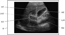
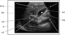
- step S1 one ultrasonic image is acquired, and the acquired ultrasonic image U2 is displayed on the display unit 8 as shown in FIG.
- step S2 when the user touches the ultrasonic image U2 displayed on the display unit 8 to specify the measurement position PM, the measurement position specification receiving unit 14 receives the user's specification of the measurement position PM.
- the measurement target recognition unit 9 recognizes a measurement target included in the recognition range R2 as shown in FIG.
- the recognition range R2 is a square range having a predetermined size and arranged so that the measurement position PM is the center, and the recognition range R2 includes the gall bladder A2 and the gate. Two measurement targets of the pulse A3 are included.
- the measurement target recognition unit 9 can recognize two measurement targets, the gallbladder A2 and the portal vein A3, included in the recognition range R2.
- step S9 the measurement object recognition unit 9 determines the number of measurement objects recognized in step S3. If the number of measurement targets recognized in step S3 is one, the process proceeds to step S4, where automatic measurement is performed on one measurement target, and the operation of the ultrasonic diagnostic apparatus 1B ends.
- step S10 the measurement order determination unit 24 determines the measurement order for the plurality of measurement objects.
- the measurement order determination unit 24 determines the measurement order of the plurality of measurement targets so that the measurement order is shorter as the measurement target is closer to the measurement position PM specified by the user on the ultrasonic image U2. Can be determined.
- the gallbladder A2 is closer to the measurement position PM than the portal vein A3 among the two measurement targets to be recognized, and therefore, the measurement order determination unit 24 determines the gall bladder A2 and the portal vein A3.
- the measurement order can be determined so that automatic measurement is performed in order.
- step S11 automatic measurement is first performed on the measurement target having the earliest measurement order according to the measurement order determined in step S10.
- the automatic measurement performed in step S11 is the same as the automatic measurement performed in step S4.
- step S12 it is determined whether the automatic measurement has been completed for all the measurement objects among the plurality of measurement objects recognized in step S3. Is done. If the automatic measurement has not been completed for all the measurement objects, the process returns to step S11, and the automatic measurement of the measurement objects having the next measurement order is performed.
- the measurement results for each measurement target can be simultaneously displayed on the display unit 8, for example.
- steps S11 and S12 are sequentially repeated until the automatic measurement is completed for all the measurement targets.
- the ultrasonic diagnostic apparatus 1 Operation ends.
- step S9 when it is determined in step S9 that there is no measurement target confirmed in step S3 because no measurement target is included in the recognition range R2, the ultrasonic diagnosis is performed without performing the automatic measurement.
- the operation of the device 1B ends. At this time, a message to the effect that the measurement target cannot be found can be displayed on the display unit 8.
- the ultrasonic diagnostic apparatus 1B of the third embodiment when a plurality of measurement targets included in the recognition range R2 are recognized, the measurement order for the plurality of measurement targets is determined, and the determined measurement is performed. Since the automatic measurement is performed sequentially according to the order, even when a plurality of measurement targets are included in the recognition range, the measurement can be easily performed as in the case of the first embodiment.
- the measurement order determination unit 24 determines the measurement order for all the measurement targets recognized by the measurement target recognition unit 9.
- the measurement order can be determined for only some of the measurement targets.
- the measurement order determination unit 24 determines two, three, and the like such that among the plurality of measurement targets recognized by the measurement target recognition unit 9, the measurement target closer to the measurement position has the earlier measurement order.
- the measurement order can be determined for only the number of measurement targets.
- the ultrasonic diagnostic apparatus 1B can perform automatic measurement only on the measurement target whose measurement order is determined.
- the measurement order is determined for only some of the measurement targets, and the automatic measurement is performed in accordance with the determined measurement order. It is possible to perform automatic measurement only on a highly useful measurement object located near the measurement position designated by.
- the measurement unit 10 converts the obtained measurement results into various types. It can be displayed on the display unit 8 in a manner. For example, as shown in FIG. 13, when the measurement target recognition unit 9 recognizes the gall bladder A2 and the portal vein A3 as the measurement targets, the measurement unit 10 uses the pair of calipers C3A for measuring the length of the gall bladder A2. , C3B and a pair of calipers C4A, C4B for measuring the length of the portal vein A3 can be made different from each other. At this time, as shown in FIG.
- the measurement unit 10 uses the mark corresponding to the pair of calipers C3A and C3B used for the measurement of the gallbladder A2 and the measurement of the portal vein A3 on the result display panel PR.
- the marks corresponding to the pair of calipers C4A and C4B can be displayed side by side with the names of the measurement targets. Thus, the user can easily grasp each measurement target and the measurement result in association with each other.
- the measurement unit 10 displays names and measurement values corresponding to a plurality of measurement targets on the display unit 8, and leads lines connecting the respective measurement targets with the corresponding names and measurement values. Can also be displayed. Further, for example, although not shown, the measuring unit 10 can display the names and measured values corresponding to the respective measurement targets in the vicinity of the plurality of measurement targets on the ultrasonic image U2. Further, for example, the measurement unit 10 may display at least one of a measurement line and a caliper displayed in a superimposed manner on a plurality of measurement targets, and a corresponding name and measurement value by color for each measurement target. it can.
- the user can easily grasp each measurement target and the measurement result in association with each other.
- various modes for displaying the measurement result can be used in appropriate combination.
- Embodiment 4 in the third embodiment, when a plurality of measurement targets are included in the recognition range R2, the measurement is automatically performed on the plurality of measurement targets. Can be selected by the user.
- FIG. 14 shows a configuration of an ultrasonic diagnostic apparatus 1C according to the fourth embodiment.
- the ultrasonic diagnostic apparatus 1C according to the fifth embodiment includes an apparatus control unit 13C instead of the apparatus control unit 13 in the ultrasonic diagnostic apparatus 1 according to the first embodiment illustrated in FIG. It was done.
- the device control unit 13C is connected to the unit 14, the operation unit 15, and the storage unit 16.
- the measurement target selection receiving unit 25 is connected to the device control unit 13C, and the measurement target selection receiving unit 25 is connected to the operation unit 15.
- the AD conversion unit 5, the image generation unit 6, the display control unit 7, the measurement target recognition unit 9, the measurement unit 10, the measurement algorithm setting unit 12, the device control unit 13C, the measurement position designation reception unit 14, and the measurement target selection reception unit 25 constitutes a processor 22C.
- the measurement target selection reception unit 25 of the processor 22C includes the measurement position PM received by the measurement position specification reception unit 14 by the measurement target recognition unit 9, and a plurality of measurement targets are recognized in a recognition range having a predetermined size. When it is recognized, a selection of one of the plurality of measurement targets is received from the user via the operation unit 15. One measurement target whose selection has been received by the measurement target selection receiving unit 25 is automatically measured under the control of the device control unit 13C.
- step S1 one ultrasonic image U2 as shown in FIG. 16 is acquired, and the acquired ultrasonic image U2 is displayed on the display unit 8.
- step S2 when the user touches the ultrasonic image U2 displayed on the display unit 8 to specify the measurement position PM, the measurement position specification receiving unit 14 receives the user's specification of the measurement position PM.
- step S3 the measurement target recognition unit 9 recognizes a measurement target included in the recognition range R2 as illustrated in FIG.
- the measurement target recognition unit 9 determines the gall bladder A2 and the portal vein A3 included in the recognition range R2. recognize.
- step S9 the measurement object recognition unit 9 determines the number of measurement objects recognized in step S3. If the number of measurement objects recognized in step S3 is one, the process proceeds to step S4, where automatic measurement is performed on one measurement object, and the operation of the ultrasonic diagnostic apparatus 1C ends.
- step S13 the measurement target selection receiving unit 25 selects one of the plurality of measurement targets from the user via the operation unit 15. Accept.
- the names of a plurality of measurement targets such as “gall bladder” and “portal vein” recognized in step S3 are displayed in a list, and the names of the measurement targets are displayed on the operation unit 15. Can be displayed on the display unit 8 via the display.
- the measurement target selection receiving unit 25 receives, for example, the gall bladder A2 as the measurement target when the user touches “gall bladder” of the “gall bladder” and the “portal vein” displayed in the measurement target list LT. .
- step S4 automatic measurement is performed on the measurement target selected by the user in step S13 and selected by the measurement target selection receiving unit 25. In this way, when the automatic measurement of one measurement target selected in step S3 is completed, the operation of the ultrasonic diagnostic apparatus 1C ends.
- step S9 If it is determined in step S9 that there is no measurement target recognized in step S3 because no measurement target is included in the recognition range R2, for example, the ultrasonic diagnosis is performed without performing the automatic measurement.
- the operation of the device 1C ends. At this time, a message to the effect that the measurement target cannot be found can be displayed on the display unit 8.
- the ultrasonic diagnostic apparatus 1 ⁇ / b> C of the fourth embodiment when a plurality of measurement targets are recognized by the measurement target recognition unit 9, the user inputs one of the plurality of measurement targets via the operation unit 15. One is selected, and automatic measurement is performed on the selected measurement target. Therefore, even if a plurality of measurement targets are recognized, automatic measurement can be performed only on the measurement target intended by the user.
- the measurement target list LT is displayed on the display unit 8, and one of a plurality of measurement target names on the measurement target list LT is selected by the user via the operation unit 15.
- the method for selecting the measurement target is not limited to this.
- the display unit 8 displays a target region line LA1 representing a closed region including only the gallbladder A2 as a measurement target and a target region line LA2 representing a closed region including only the portal vein A3 as a measurement target.
- the user can touch either the inside of the target area line LA1 or the inside of the target area line LA2 to select the measurement target.
- the measurement target can be selected by displaying the target region line for each of the plurality of measurement targets and allowing the user to touch the inside of each target region line.
- the plurality of target area lines displayed on the display unit 8 in this manner can be displayed in different colors from each other. Also, instead of the target area line, a contour line representing the contour of each measurement target can be displayed, and the inside of each contour line can be displayed in different colors.
- the measurement target selection receiving unit 25 receives the selection of the set number of measurement targets from among the plurality of measurement targets. Can be.
- FIG. 18 shows a configuration of an ultrasonic diagnostic apparatus 1D according to the fifth embodiment.
- the ultrasonic diagnostic apparatus 1D according to the fifth embodiment is different from the ultrasonic diagnostic apparatus 1 according to the first embodiment shown in FIG. 1 in that a device control unit 13D is provided instead of the device control unit 13 and a recognition range determination unit 26 is provided. It was done.
- a recognition range determination unit 26 is connected to the measurement target recognition unit 9, and a display control unit 7 is connected to the recognition range determination unit 26.
- the transmission unit 3, the reception unit 4, the image generation unit 6, the display control unit 7, the measurement target recognition unit 9, the measurement unit 10, the measurement algorithm setting unit 12, the measurement position designation reception unit 14, the operation unit 15, and the storage unit 16 The device control unit 13D is connected to the recognition range determination unit 26.
- the AD converter 5, the image generator 6, the display controller 7, the measurement object recognition unit 9, the measurement unit 10, the measurement algorithm setting unit 12, the device control unit 13C, the measurement position designation reception unit 14, the recognition range determination unit 26 Constitutes a processor 22D.
- the recognition range determination unit 26 of the processor 22D can determine the recognition range after setting the size of the recognition range in accordance with the touch operation of the user's finger via the operation unit 15. At this time, for example, the recognition range determination unit 26 enlarges and reduces the recognition range of a predetermined size set in advance in accordance with a touch operation by a user's finger, thereby changing the size of the recognition range. Can be determined.
- Step S1 to S4 in the flowchart of FIG. 19 are the same as steps S1 to S4 in the flowchart of FIG.
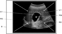
- step S1 one ultrasonic image is acquired, and the acquired ultrasonic image U1 is displayed on the display unit 8 as shown in FIG.
- step S2 when the user touches the ultrasonic image U1 displayed on the display unit 8 to specify the measurement position PM, the measurement position specification receiving unit 14 receives the user's specification of the measurement position PM.
- the recognition range determination unit 26 sets the size of the recognition range in accordance with the touch operation of the user's finger through the operation unit 15, and determines the recognition range. For example, as shown in FIG. 20, the recognition range determination unit 26 can set the recognition range to be larger as the time during which the user touches the measurement range PM is longer.
- FIG. 20 shows a recognition range R3 of a square having a predetermined size and arranged so that the measurement position PM is at the center. Although the recognition range R3 includes only a part of the area of the gall bladder A1, the recognition range R3 includes the entire area of the gall bladder A1 by continuously touching the measurement position PM with the user's finger. The range is expanded to the range R4.
- the recognition range determination unit 26 displays, via the display control unit 7, the display unit 8 that the recognition range is gradually expanded with time. To be displayed.
- a recognition range R3 having a predetermined size set as an initial value is displayed on the display unit 8, and the user's finger is moved to the ultrasonic image U2.
- the display unit 8 displays a state in which the recognition range R3 is gradually expanded as time elapses until the user moves away from above. If the user's finger moves away from the ultrasonic image U2 when the recognition range is expanded, for example, to the recognition range R4, the recognition range R4 is set as the recognition range in which the measurement target recognition unit 9 performs recognition of the measurement target. Is determined.
- the measurement target recognition unit 9 recognizes a measurement target included in the recognition range R4 determined in step S13.
- the gall bladder A1 is included in the recognition range R4, and the measurement target recognition unit 9 can recognize the gall bladder A1.
- step S4 automatic measurement is performed on the measurement object recognized in step S3, and the operation of the ultrasonic diagnostic apparatus 1D ends.
- the ultrasonic diagnostic apparatus 1D of the fifth embodiment when the user touches the position on the ultrasonic image U1 and specifies the measurement position PM, the user's finger moves to the position on the ultrasonic image U1. The longer the time that is touched, the larger the recognition range is set.For example, even if the user specifies a position away from the target measurement target as the measurement position, the target measurement is set within the recognition range. The measurement can be reliably performed by including the target.
- the recognition range R4 is determined by enlarging the recognition range R3 having the determined size.
- the recognition range can be reduced.
- the recognition range determination unit 26 can also set the recognition range smaller as the time during which the user touches the measurement position PM becomes longer.
- the recognition range R5 including the entire display area of the ultrasound image U1 on the display unit 8 is changed to include only the gallbladder A1 as a measurement target.
- a recognition range R6 As a recognition range R6.
- the recognition range determination unit 26 displays, via the display control unit 7, the display unit 8 via the display control unit 7 how the recognition range is gradually reduced with time. To be displayed. At this time, for example, when the measurement position PM is touched by the user's finger, the recognition range R5 including the entire display area of the ultrasonic image U1 is displayed on the display unit 8, and the user's finger leaves the ultrasonic image U1. Until then, a state in which the recognition range R5 is gradually reduced is displayed on the display unit 8.
- the recognition range R6 is set as a recognition range in which the measurement target recognition unit 9 performs recognition of the measurement target. Is determined.
- the recognition range can be set so that the user includes only the area necessary for recognition of the target measurement target. Therefore, the calculation load when the measurement target recognition unit 9 recognizes the measurement target can be reduced, and the measurement target recognition unit 9 can more quickly recognize the measurement target.
- the ultrasound image U2 includes the gallbladder A2 and the portal vein A3, and the measurement position PM on the ultrasound image U2 is continuously touched by the user, so that the gallbladder A2 and the portal vein are displayed.
- the recognition range R7 including a part of A3 can be expanded to the recognition range R8 including the entire gallbladder A2 and the portal vein A3.
- the ultrasonic diagnostic apparatus 1 ⁇ / b> D of the fifth embodiment when the measurement is performed on a plurality of measurement targets, the plurality of target measurement targets can be easily included in the recognition range. Can be.
- the recognition range R9 including the entire display area of the ultrasonic image U2 on the display unit 8 is limited to only the gallbladder A2. It can also be reduced to the recognition range R10 included as a measurement target. In this manner, by reducing the recognition range, the recognition range can be set so that the user includes only the target measurement target. Thereby, the calculation load when the measurement target recognition unit 9 recognizes the measurement target can be reduced, and the measurement target recognition unit 9 can more quickly recognize the measurement target.
- the recognition range determination unit 26 determines the time at which the user's finger touches the position on the ultrasonic image.
- the size of the recognition range can be set according to the length of the recognition range, but the mode of setting the size of the recognition range is not limited to this.
- the recognition range determination unit 26 specifies the measurement position PM by touching the display screen of the display unit 8 so that the user's finger overlaps the ultrasonic image, and further moves while the user's finger touches the display screen. Then, the size of the recognition range can be set according to the moving direction and the moving distance of the user's finger on the ultrasonic image. For example, when the user's finger moves to the right while touching the display screen of the display unit 8, the recognition range determination unit 26 gradually expands the recognition range according to the moving distance, and the user's finger When the display screen 8 is moved to the left while touching the display screen, the recognition range can be gradually reduced according to the movement distance.
- the moving direction of the user's finger for enlarging and reducing the recognition range is not limited to the left-right direction, but may be set to any direction such as a vertical direction, an oblique direction, and the like.
- the recognition range determination unit 26 can more easily set the size of the recognition range to the size of the recognition range according to the purpose of the user.
- the recognition range determination unit 26 can detect the pressure of the user's finger detected by the pressure sensor.
- the size of the recognition range can be set according to the size of.
- the recognition range determination unit 26 can expand the recognition range as the pressure detected by the pressure sensor increases.
- the recognition range determination unit 26 can reduce the recognition range as the pressure detected by the pressure sensor increases.
- the operation unit 15 in the first to fifth embodiments includes a touch sensor
- the configuration of the operation unit 15 is not limited to this.
- an interface such as a keyboard, a mouse, and a trackball that can be input by a user can be used.
- the measurement target is measured based on the ultrasonic image.
- the measurement target can be measured also on acoustic wave images other than the ultrasonic image.
- the measurement target can be measured also for a photoacoustic wave image and a composite image in which an ultrasonic image and a photoacoustic wave image are superimposed.
Landscapes
- Health & Medical Sciences (AREA)
- Life Sciences & Earth Sciences (AREA)
- Engineering & Computer Science (AREA)
- Physics & Mathematics (AREA)
- Biomedical Technology (AREA)
- Public Health (AREA)
- Medical Informatics (AREA)
- General Health & Medical Sciences (AREA)
- Veterinary Medicine (AREA)
- Biophysics (AREA)
- Heart & Thoracic Surgery (AREA)
- Molecular Biology (AREA)
- Surgery (AREA)
- Animal Behavior & Ethology (AREA)
- Pathology (AREA)
- Radiology & Medical Imaging (AREA)
- Nuclear Medicine, Radiotherapy & Molecular Imaging (AREA)
- Theoretical Computer Science (AREA)
- General Engineering & Computer Science (AREA)
- Human Computer Interaction (AREA)
- General Physics & Mathematics (AREA)
- Computer Vision & Pattern Recognition (AREA)
- Physiology (AREA)
- Acoustics & Sound (AREA)
- Primary Health Care (AREA)
- Epidemiology (AREA)
- Business, Economics & Management (AREA)
- General Business, Economics & Management (AREA)
- Ultra Sonic Daignosis Equipment (AREA)
Abstract
Description
もしくは、操作部を介してユーザによりなされた、計測対象に対する計測を開始する指示を受け付ける計測実行指示受付部を備え、計測実行指示受付部により計測対象に対する計測を開始する指示が受け付けられると、認識範囲決定部による認識範囲の決定、計測対象認識部による計測対象の認識、計測アルゴリズム設定部による計測アルゴリズムの設定、および、計測部による計測と計測結果の表示が、順次、自動的になされてもよい。
この際に、計測部は、複数の計測対象に対する計測結果を、それぞれ、音響波画像上の複数の計測対象に対応付けて表示部に表示させることができる。
この際に、計測順序決定部は、音響波画像上において計測位置からの距離が近いほど計測順序が早くなるように、複数の計測対象に計測順序を付与することができる。
あるいは、ユーザの指によるタッチ操作に応じて認識範囲の大きさを設定する認識範囲決定部を備えることもできる。
また、認識範囲決定部は、音響波画像上の計測位置がユーザの指によりタッチされ且つユーザの指が音響波画像上において移動された場合に、音響波画像上におけるユーザの指の移動方向および移動距離に応じて認識範囲の大きさを設定することもできる。
また、操作部は、表示部およびタッチセンサに重ねて配置された圧力センサを含み、認識範囲決定部は、圧力センサにより検知されたユーザの指の圧力の大きさに応じて認識範囲の大きさを設定することもできる。
実施の形態1
図1に、本発明の実施の形態1に係る超音波診断装置1の構成を示す。図1に示すように、超音波診断装置1は、振動子アレイ2を備えており、振動子アレイ2に、それぞれ送信部3および受信部4が接続されている。受信部4には、AD(Analog Digital:アナログデジタル)変換部5、画像生成部6、表示制御部7および表示部8が順次接続されており、表示部8に重ねて操作部15が配置されている。また、画像生成部6に計測対象認識部9および計測部10がそれぞれ接続されており、計測対象認識部9に、計測部10が接続され、計測部10に、表示制御部7が接続されている。また、計測対象認識部9に、計測アルゴリズム設定部12が接続されており、計測アルゴリズム設定部12に、計測部10が接続されている。
さらに、振動子アレイ2、送信部3および受信部4により、超音波プローブ21が構成されており、AD変換部5、画像生成部6、表示制御部7、計測対象認識部9、計測部10、計測アルゴリズム設定部12、装置制御部13、計測位置指定受付部14により、プロセッサ22が構成されている。
プロセッサ22の画像生成部6は、図2に示すように、信号処理部17、DSC(Digital Scan Converter:デジタルスキャンコンバータ)18および画像処理部19が直列接続された構成を有している。信号処理部17は、装置制御部13からの制御信号に応じて選択された受信遅延パターンに基づき、設定された音速に従う各素子データにそれぞれの遅延を与えて加算(整相加算)を施す、受信フォーカス処理を行う。この受信フォーカス処理により、超音波エコーの焦点が絞り込まれた音線信号が生成される。また、信号処理部17は、生成された音線信号に対して、超音波が反射した位置の深度に応じて伝搬距離に起因する減衰の補正を施した後、包絡線検波処理を施して、被検体内の組織に関する断層画像情報であるBモード画像信号を生成する。このように生成されたBモード画像信号は、DSC18に出力される。
超音波診断装置1の表示部8は、図示しない表示画面を有しており、表示制御部7の制御の下、画像生成部6により生成された超音波画像、計測部10により算出された計測結果等を、表示画面に表示する。また、表示部8は、例えば、LCD(Liquid Crystal Display:液晶ディスプレイ)、有機ELディスプレイ(Organic Electroluminescence Display)等のディスプレイ装置を含む。
また、例えば、計測対象認識部9は、典型的なパターンデータをテンプレートとして予め記憶しておき、画像内をテンプレートでサーチしながらパターンデータに対する類似度を算出し、類似度が閾値以上かつ最大となった場所に計測対象が存在するとみなすことにより、計測対象を認識することもできる。
ここで、アルゴリズムとは、計測等の目的を達成するための計算手段を定めたものであって、例えば、ソフトウェアのプログラムとして装置に実装され、CPU(Central Processing Unit:中央処理装置)により実行されるものである。計測アルゴリズム設定部12に設定される計測アルゴリズムとしては、一般的に使用される公知のアルゴリズムを使用することができる。
まず、ステップS1において、超音波診断装置1により少なくとも1枚の超音波画像が取得され、取得された1枚の超音波画像が表示部8に表示される。表示部8に表示される1枚の超音波画像として、例えば、超音波プローブ21を用いてその場で撮影された超音波画像が使用されることができる。この場合には、例えば、超音波プローブ21により複数の超音波画像が連続的に撮影され、超音波画像が表示部8に順次表示されている状態において、ユーザが操作部15を介した入力操作を行うことにより、表示部8において1枚の超音波画像をフリーズ表示させることができる。また、表示部8に表示される1枚の超音波画像として、図示しない外部メモリから取得された超音波画像が使用されることもできる。
ステップS4は、図5に示すように、ステップS5~ステップS7の3つのステップにより構成されている。まず、ステップS5において、計測アルゴリズム設定部12は、ステップS3で認識された計測対象に対する計測アルゴリズムを設定する。
このようにして表示部8に計測結果が表示されると、ステップS5~ステップS7からなるステップS5の処理が完了し、超音波診断装置1の動作が終了する。
実施の形態1では、表示部8に表示されている超音波画像U1がユーザによりタッチされて計測位置PMが指定されると、計測位置指定受付部14により計測位置PMの指定が受け付けられ、認識範囲R1の決定、計測対象の認識、計測アルゴリズムの設定、計測対象の計測、計測結果の表示からなる一連の動作が自動的に行われるが、操作部15を介したユーザからの指示をトリガとして、一連の動作が実行されることもできる。
実施の形態2の超音波診断装置1Aにおいて、送信部3、受信部4、画像生成部6、表示制御部7、計測対象認識部9、計測部10、計測アルゴリズム設定部12、計測位置指定受付部14、操作部15および格納部16に、装置制御部13Aが接続されている。また、装置制御部13Aに、計測実行指示受付部23が接続され、計測実行指示受付部23は、さらに、操作部15に接続している。
まず、ステップS1において、1枚の超音波画像U1が取得され、取得された超音波画像U1が表示部8に表示される。
ステップS2において、ユーザが表示部8に表示されている超音波画像U1をタッチして計測位置PMを指定すると、計測位置指定受付部14は、ユーザによる計測位置PMの指定を受け付ける。
続くステップS4において、ステップS3で認識された計測対象に対する自動計測が行われ、超音波診断装置1Aの動作が終了する。
実施の形態1および実施の形態2では、超音波画像U1に含まれる1つの計測対象に対する認識および計測がなされているが、複数の計測対象に対する認識および計測がなされることもできる。
図10に、実施の形態3に係る超音波診断装置1Bの構成を示す。実施の形態3の超音波診断装置1Bは、図1に示す実施の形態1の超音波診断装置1において、装置制御部13の代わりに装置制御部13Bを備え、計測順序決定部24が追加されたものである。
計測部10は、装置制御部13Bの制御の下、計測順序決定部24により決定された計測順序に従って複数の計測対象の計測を行う。
ステップS1において、1枚の超音波画像が取得され、図12に示すように、取得された超音波画像U2が表示部8に表示される。
ステップS2において、ユーザが表示部8に表示されている超音波画像U2をタッチして計測位置PMを指定すると、計測位置指定受付部14は、ユーザによる計測位置PMの指定を受け付ける。
例えば、図13に示すように、計測対象として胆嚢A2および門脈A3が計測対象認識部9により認識された場合に、計測部10は、胆嚢A2の長さを計測するための一対のキャリパC3A,C3Bの形状と、門脈A3の長さを計測するための一対のキャリパC4A、C4Bの形状とを、互いに異ならせることができる。この際に、図13に示すように、計測部10は、結果表示パネルPRにおいて、胆嚢A2の計測に使用された一対のキャリパC3A、C3Bに対応するマークと、門脈A3の計測に使用された一対のキャリパC4A、C4Bに対応するマークを、計測対象の名称に並べて表示させることができる。これにより、ユーザは、それぞれの計測対象と計測結果とを、容易に対応付けて把握することができる。
また、例えば、図示しないが、計測部10は、超音波画像U2上の複数の計測対象の近傍に、それぞれの計測対象に対応する名称および計測値を表示させることもできる。
また、例えば、計測部10は、複数の計測対象に重畳して表示される計測線およびキャリパの少なくとも一方と、それぞれ対応する名称および計測値とを、計測対象毎に色分けして表示させることもできる。
実施の形態3では、認識範囲R2内に複数の計測対象が含まれている場合に、複数の計測対象に対して自動的に計測がなされているが、複数の計測対象のうち、実際に計測を行う計測対象をユーザに選択させることもできる。
実施の形態5の超音波診断装置1Cにおいて、送信部3、受信部4、画像生成部6、表示制御部7、計測対象認識部9、計測部10、計測アルゴリズム設定部12、計測位置指定受付部14、操作部15および格納部16に、装置制御部13Cが接続されている。また、装置制御部13Cに、計測対象選択受付部25が接続されており、計測対象選択受付部25は、操作部15に接続している。
まず、ステップS1において、図16に示すような1枚の超音波画像U2が取得され、取得された超音波画像U2が表示部8に表示される。
ステップS2において、ユーザが表示部8に表示されている超音波画像U2をタッチして計測位置PMを指定すると、計測位置指定受付部14は、ユーザによる計測位置PMの指定を受け付ける。
例えば、図17に示すように、計測対象として胆嚢A2のみを含む閉じた領域を表す対象領域線LA1と、計測対象として門脈A3のみを含む閉じた領域を表す対象領域線LA2を表示部8に表示させ、対象領域線LA1の内側と対象領域線LA2の内側のいずれか一方をユーザにタッチさせることにより、計測対象を選択させることができる。このように、複数の計測対象に対してそれぞれ対象領域線を表示させ、それぞれの対象領域線の内側をユーザにタッチさせることにより、計測対象を選択させることができる。
このようにして表示部8に表示された複数の対象領域線は、それぞれ互いに異なる色で表示されることができる。また、対象領域線の代わりに、それぞれの計測対象の輪郭を表す輪郭線が表示されることもでき、それぞれの輪郭線の内側が、互いに異なる色で表示されることもできる。
実施の形態1、2における認識範囲R1および実施の形態3、4における認識範囲R2は、いずれも定められた大きさを有しているが、操作部15を介したユーザの操作により、認識範囲の大きさを変更することもできる。図18に、実施の形態5の超音波診断装置1Dの構成を示す。実施の形態5の超音波診断装置1Dは、図1に示す実施の形態1の超音波診断装置1において、装置制御部13の代わりに装置制御部13Dが備えられ、認識範囲決定部26が設けられたものである。
さらに、AD変換部5、画像生成部6、表示制御部7、計測対象認識部9、計測部10、計測アルゴリズム設定部12、装置制御部13C、計測位置指定受付部14、認識範囲決定部26により、プロセッサ22Dが構成されている。
ステップS1において、1枚の超音波画像が取得され、図20に示すように、取得された超音波画像U1が表示部8に表示される。
ステップS2において、ユーザが表示部8に表示されている超音波画像U1をタッチして計測位置PMを指定すると、計測位置指定受付部14は、ユーザによる計測位置PMの指定を受け付ける。
続くステップS4において、ステップS3で認識された計測対象に対する自動計測が行われ、超音波診断装置1Dの動作が終了する。
例えば、図21に示すように、認識範囲決定部26は、ユーザが計測位置PMをタッチしている時間が長くなるほど、認識範囲を小さく設定することもできる。図21に示す例では、超音波画像U1上の計測位置PMがユーザによりタッチされ続けることにより、表示部8における超音波画像U1の表示領域全体を含む認識範囲R5が、胆嚢A1のみを計測対象として含む認識範囲R6にまで縮小されている。
例えば、図22に示すように、超音波画像U2内に胆嚢A2と門脈A3が含まれており、超音波画像U2上の計測位置PMがユーザによりタッチされ続けることにより、胆嚢A2と門脈A3の一部とを含む認識範囲R7が、胆嚢A2と門脈A3の全体を含む認識範囲R8にまで拡大されることができる。このように、実施の形態5の超音波診断装置1Dによれば、複数の計測対象に対する計測が目的とされている場合に、目的とする複数の計測対象を認識範囲内に容易に含ませることができる。
これにより、認識範囲決定部26は、認識範囲の大きさをユーザの目的に応じた認識範囲の大きさに、さらに容易に設定することができる。
Claims (15)
- 取得した音響波画像を表示する表示部と、
ユーザが入力操作を行うための操作部と、
前記操作部を介して前記ユーザから、前記表示部に表示された前記音響波画像上の計測位置の指定を受け付ける計測位置指定受付部と、
前記計測位置指定受付部により受け付けられた前記計測位置に基づいて決定される認識範囲の前記音響波画像に含まれる計測対象を認識する計測対象認識部と、
前記計測対象認識部により認識された前記計測対象に基づいて計測アルゴリズムを設定する計測アルゴリズム設定部と、
前記計測アルゴリズム設定部により設定された前記計測アルゴリズムに基づいて、前記音響波画像上の前記計測対象に対する計測を行い、計測結果を前記表示部に表示させる計測部と
を備える音響波診断装置。 - 前記計測位置指定受付部により前記計測位置が受け付けられると、前記計測対象認識部による前記計測対象の認識、前記計測アルゴリズム設定部による前記計測アルゴリズムの設定、および、前記計測部による計測と前記計測結果の表示が、順次、自動的になされる請求項1に記載の音響波診断装置。
- 前記操作部を介してユーザによりなされた、前記計測対象に対する計測を開始する指示を受け付ける計測実行指示受付部を備え、
前記計測実行指示受付部により前記計測対象に対する計測を開始する指示が受け付けられると、前記計測対象認識部による前記計測対象の認識、前記計測アルゴリズム設定部による前記計測アルゴリズムの設定、および、前記計測部による計測と前記計測結果の表示が、順次、自動的になされる請求項1に記載の音響波診断装置。 - 前記計測対象認識部により、前記認識範囲において複数の前記計測対象が認識された場合に、
前記計測アルゴリズム設定部は、前記複数の計測対象に対してそれぞれ前記計測アルゴリズムを設定し、
前記計測部は、前記複数の計測対象に対してそれぞれ計測を行い、それぞれの計測結果を前記表示部に表示させる請求項1~3のいずれか一項に記載の音響波診断装置。 - 前記計測部は、前記複数の計測対象に対する計測結果を、それぞれ、前記音響波画像上の前記複数の計測対象に対応付けて前記表示部に表示させる請求項4に記載の音響波診断装置。
- 前記計測対象認識部により、前記認識範囲において複数の前記計測対象が認識された場合に、前記複数の計測対象の計測順序を決定する計測順序決定部を備え、
前記計測アルゴリズム設定部は、前記計測順序決定部により決定された前記計測順序に従って前記複数の計測対象に順次前記計測アルゴリズムを設定し、
前記計測部は、前記計測アルゴリズム設定部により前記計測アルゴリズムが設定された前記計測対象から順次計測を行い、前記複数の計測対象に対する計測結果を前記表示部に表示させる請求項4または5に記載の音響波診断装置。 - 前記計測順序決定部は、前記音響波画像上において前記計測位置からの距離が近いほど前記計測順序が早くなるように、前記複数の計測対象に前記計測順序を付与する請求項6に記載の音響波診断装置。
- 前記計測対象認識部により、前記認識範囲において複数の前記計測対象が認識された場合に、前記操作部を介してユーザから、前記複数の計測対象のうち1つの前記計測対象の選択を受け付ける計測対象選択受付部を備え、
前記計測アルゴリズム設定部は、前記計測対象選択受付部により選択が受け付けられた前記1つの計測対象に基づいて前記計測アルゴリズムを設定し、
前記計測部は、前記計測アルゴリズムに基づいて前記1つの計測対象に対する計測を行い、計測結果を前記表示部に表示させる請求項4または5に記載の音響波診断装置。 - 前記操作部は、前記表示部に重ねて配置されたタッチセンサを含み、
前記計測位置指定受付部は、前記表示部に表示された前記音響波画像上において前記ユーザの指によりタッチされた位置を前記計測位置として受け付ける請求項1~8のいずれか一項に記載の音響波診断装置。 - 前記認識範囲は、定められた大きさを有する請求項1~9のいずれか一項に記載の音響波診断装置。
- 前記ユーザの指によるタッチ操作に応じて前記認識範囲の大きさを設定する認識範囲決定部を備える請求項9に記載の音響波診断装置。
- 前記認識範囲決定部は、前記音響波画像上の前記計測位置が前記ユーザの指によりタッチされた時間の長さに応じて前記認識範囲の大きさを設定する請求項11に記載の音響波診断装置。
- 前記認識範囲決定部は、前記音響波画像上の前記計測位置が前記ユーザの指によりタッチされ且つ前記ユーザの指が前記音響波画像上において移動された場合に、前記音響波画像上における前記ユーザの指の移動方向および移動距離に応じて前記認識範囲の大きさを設定する請求項11に記載の音響波診断装置。
- 前記操作部は、前記表示部および前記タッチセンサに重ねて配置された圧力センサを含み、
前記認識範囲決定部は、前記圧力センサにより検知された前記ユーザの指の圧力の大きさに応じて前記認識範囲の大きさを設定する請求項11に記載の音響波診断装置。 - 取得した音響波画像を表示し、
ユーザによる、前記音響波画像上の計測位置の指定を受け付け、
受け付けられた前記計測位置に基づいて前記音響波画像上の認識範囲を決定し、
決定された前記認識範囲に含まれる計測対象を認識し、
認識された前記計測対象に基づいて計測アルゴリズムを設定し、
設定された前記計測アルゴリズムに基づいて、前記音響波画像から前記計測対象に対する計測を行い、
前記計測対象に対する計測結果を表示する
音響波診断装置の制御方法。
Priority Applications (5)
| Application Number | Priority Date | Filing Date | Title |
|---|---|---|---|
| CN201980044574.XA CN112367921B (zh) | 2018-07-02 | 2019-05-21 | 声波诊断装置及声波诊断装置的控制方法 |
| JP2020528707A JP6951576B2 (ja) | 2018-07-02 | 2019-05-21 | 音響波診断装置および音響波診断装置の制御方法 |
| CN202411282108.4A CN118902495A (zh) | 2018-07-02 | 2019-05-21 | 声波诊断装置及声波诊断装置的控制方法 |
| EP19831559.0A EP3818944B1 (en) | 2018-07-02 | 2019-05-21 | Acoustic diagnostic apparatus and method for controlling acoustic diagnostic apparatus |
| US17/134,887 US12419615B2 (en) | 2018-07-02 | 2020-12-28 | Acoustic wave diagnostic apparatus and method of controlling acoustic wave diagnostic apparatus |
Applications Claiming Priority (2)
| Application Number | Priority Date | Filing Date | Title |
|---|---|---|---|
| JP2018-126175 | 2018-07-02 | ||
| JP2018126175 | 2018-07-02 |
Related Child Applications (1)
| Application Number | Title | Priority Date | Filing Date |
|---|---|---|---|
| US17/134,887 Continuation US12419615B2 (en) | 2018-07-02 | 2020-12-28 | Acoustic wave diagnostic apparatus and method of controlling acoustic wave diagnostic apparatus |
Publications (1)
| Publication Number | Publication Date |
|---|---|
| WO2020008743A1 true WO2020008743A1 (ja) | 2020-01-09 |
Family
ID=69059574
Family Applications (1)
| Application Number | Title | Priority Date | Filing Date |
|---|---|---|---|
| PCT/JP2019/020018 Ceased WO2020008743A1 (ja) | 2018-07-02 | 2019-05-21 | 音響波診断装置および音響波診断装置の制御方法 |
Country Status (5)
| Country | Link |
|---|---|
| US (1) | US12419615B2 (ja) |
| EP (1) | EP3818944B1 (ja) |
| JP (1) | JP6951576B2 (ja) |
| CN (2) | CN112367921B (ja) |
| WO (1) | WO2020008743A1 (ja) |
Cited By (2)
| Publication number | Priority date | Publication date | Assignee | Title |
|---|---|---|---|---|
| JP2023512351A (ja) * | 2020-01-29 | 2023-03-24 | エアーズ メディカル カンパニー リミテッド | 身体の目的ターゲットの位置確認方法 |
| US20240423592A1 (en) * | 2022-03-09 | 2024-12-26 | Fujifilm Corporation | Ultrasound diagnostic apparatus, control method of ultrasound diagnostic apparatus, and distance measurement device |
Families Citing this family (4)
| Publication number | Priority date | Publication date | Assignee | Title |
|---|---|---|---|---|
| JP7379052B2 (ja) * | 2019-09-30 | 2023-11-14 | キヤノン株式会社 | 表示制御装置、方法及びプログラム |
| CN114063331B (zh) * | 2020-07-31 | 2023-10-24 | 京东方科技集团股份有限公司 | 超声调光系统及调光窗总成 |
| CN116529629A (zh) * | 2020-12-01 | 2023-08-01 | 皇家飞利浦有限公司 | 使用发射速度系统、设备和方法的回顾性发射聚焦 |
| JP2024039871A (ja) * | 2022-09-12 | 2024-03-25 | 富士フイルム株式会社 | 超音波診断装置および超音波診断装置の制御方法 |
Citations (2)
| Publication number | Priority date | Publication date | Assignee | Title |
|---|---|---|---|---|
| JP2013111434A (ja) | 2011-12-01 | 2013-06-10 | Toshiba Corp | 画像処理装置、超音波診断装置及び画像処理プログラム |
| JP2017164077A (ja) * | 2016-03-15 | 2017-09-21 | 株式会社日立製作所 | 超音波診断装置 |
Family Cites Families (23)
| Publication number | Priority date | Publication date | Assignee | Title |
|---|---|---|---|---|
| AU2006254689B2 (en) * | 2005-06-02 | 2012-03-08 | Salient Imaging, Inc. | System and method of computer-aided detection |
| JP4832518B2 (ja) * | 2005-11-02 | 2011-12-07 | オリンパス株式会社 | 画像処理装置、その画像処理方法及び画像処理プログラム |
| JP2010512218A (ja) * | 2006-12-12 | 2010-04-22 | コーニンクレッカ フィリップス エレクトロニクス エヌ ヴィ | 医用イメージングシステム |
| US20080267499A1 (en) * | 2007-04-30 | 2008-10-30 | General Electric Company | Method and system for automatic detection of objects in an image |
| US8968200B2 (en) | 2008-02-21 | 2015-03-03 | Hitachi Medical Corporation | Ultrasonic elastography for cross sectional tissue measurement method and apparatus |
| JP2010148811A (ja) * | 2008-12-26 | 2010-07-08 | Panasonic Corp | 超音波診断装置 |
| CN103347450B (zh) * | 2011-02-04 | 2015-07-08 | 株式会社日立医疗器械 | 超声波诊断装置及方法 |
| JP2014023715A (ja) * | 2012-07-26 | 2014-02-06 | Sharp Corp | 測定支援装置、測定支援方法、制御プログラム、および、記録媒体 |
| US9913625B2 (en) * | 2013-03-29 | 2018-03-13 | Hitachi, Ltd. | Medical diagnosis device and measurement method thereof |
| KR101653610B1 (ko) * | 2013-11-21 | 2016-09-02 | 삼성전자주식회사 | 압력 변화에 기초한 영상 표시 방법, 영상 처리 장치, 방사선 촬영 장치 및 자기 공명 영상 장치 |
| JP2015100479A (ja) * | 2013-11-22 | 2015-06-04 | 日立アロカメディカル株式会社 | 超音波画像処理装置 |
| KR102185726B1 (ko) * | 2014-01-28 | 2020-12-02 | 삼성메디슨 주식회사 | 관심 영역에 대응하는 초음파 영상 표시 방법 및 이를 위한 초음파 장치 |
| EP3127486B1 (en) * | 2014-03-20 | 2024-07-31 | Shenzhen Mindray Bio-Medical Electronics Co., Ltd. | Method and device for automatic identification of measurement item and ultrasound imaging apparatus |
| KR102294194B1 (ko) * | 2014-08-05 | 2021-08-26 | 삼성전자주식회사 | 관심영역의 시각화 장치 및 방법 |
| KR101599891B1 (ko) * | 2014-09-19 | 2016-03-04 | 삼성전자주식회사 | 초음파 진단장치, 방법 및 컴퓨터 판독 가능한 저장매체 |
| EP3106096B1 (en) * | 2015-06-12 | 2020-02-19 | Samsung Medison Co., Ltd. | Method and apparatus for displaying ultrasound images |
| WO2017216238A1 (en) * | 2016-06-15 | 2017-12-21 | Koninklijke Philips N.V. | A camera-based vital sign measurement device |
| JP6668214B2 (ja) * | 2016-10-12 | 2020-03-18 | 株式会社日立製作所 | 超音波撮像装置及び硬さの算出方法 |
| WO2018079852A1 (ja) * | 2016-10-31 | 2018-05-03 | 株式会社ディー・ディー・エス | 皮膚情報処理プログラム及び皮膚情報処理装置 |
| EP3673816B1 (en) * | 2017-08-25 | 2025-06-04 | FUJIFILM Corporation | Acoustic wave diagnostic apparatus and method for controlling acoustic wave diagnostic apparatus |
| EP3698722A4 (en) * | 2017-10-17 | 2020-12-23 | FUJIFILM Corporation | ACOUSTIC WAVES DIAGNOSIS APPARATUS AND PROCESS FOR CONTROLLING AN ACOUSTIC WAVE DIAGNOSIS APPARATUS |
| US11264135B2 (en) * | 2017-11-10 | 2022-03-01 | Siemens Medical Solutions Usa, Inc. | Machine-aided workflow in ultrasound imaging |
| EP3818943B1 (en) * | 2018-07-02 | 2024-08-21 | FUJIFILM Corporation | Acoustic wave diagnostic device and method for controlling acoustic wave diagnostic device |
-
2019
- 2019-05-21 CN CN201980044574.XA patent/CN112367921B/zh active Active
- 2019-05-21 JP JP2020528707A patent/JP6951576B2/ja active Active
- 2019-05-21 CN CN202411282108.4A patent/CN118902495A/zh active Pending
- 2019-05-21 WO PCT/JP2019/020018 patent/WO2020008743A1/ja not_active Ceased
- 2019-05-21 EP EP19831559.0A patent/EP3818944B1/en active Active
-
2020
- 2020-12-28 US US17/134,887 patent/US12419615B2/en active Active
Patent Citations (2)
| Publication number | Priority date | Publication date | Assignee | Title |
|---|---|---|---|---|
| JP2013111434A (ja) | 2011-12-01 | 2013-06-10 | Toshiba Corp | 画像処理装置、超音波診断装置及び画像処理プログラム |
| JP2017164077A (ja) * | 2016-03-15 | 2017-09-21 | 株式会社日立製作所 | 超音波診断装置 |
Non-Patent Citations (2)
| Title |
|---|
| CSURKA ET AL.: "Visual Categorization with Bags of Keypoints", PROC. OF ECCV WORKSHOP ON STATISTICAL LEARNING IN COMPUTER VISION, 2004, pages 59 - 74 |
| See also references of EP3818944A4 |
Cited By (3)
| Publication number | Priority date | Publication date | Assignee | Title |
|---|---|---|---|---|
| JP2023512351A (ja) * | 2020-01-29 | 2023-03-24 | エアーズ メディカル カンパニー リミテッド | 身体の目的ターゲットの位置確認方法 |
| US12205287B2 (en) | 2020-01-29 | 2025-01-21 | Airs Medical Co., Ltd. | Method for determining location of target of body |
| US20240423592A1 (en) * | 2022-03-09 | 2024-12-26 | Fujifilm Corporation | Ultrasound diagnostic apparatus, control method of ultrasound diagnostic apparatus, and distance measurement device |
Also Published As
| Publication number | Publication date |
|---|---|
| EP3818944A1 (en) | 2021-05-12 |
| US12419615B2 (en) | 2025-09-23 |
| EP3818944A4 (en) | 2021-09-01 |
| CN118902495A (zh) | 2024-11-08 |
| US20210113196A1 (en) | 2021-04-22 |
| CN112367921B (zh) | 2024-09-24 |
| CN112367921A (zh) | 2021-02-12 |
| EP3818944B1 (en) | 2026-03-25 |
| JPWO2020008743A1 (ja) | 2021-07-01 |
| JP6951576B2 (ja) | 2021-10-20 |
Similar Documents
| Publication | Publication Date | Title |
|---|---|---|
| JP6951576B2 (ja) | 音響波診断装置および音響波診断装置の制御方法 | |
| US12303331B2 (en) | Ultrasound diagnostic apparatus and control method of ultrasound diagnostic apparatus | |
| JP6937914B2 (ja) | 音響波診断装置および音響波診断装置の制御方法 | |
| EP3888557B1 (en) | Ultrasonic diagnostic device and method for controlling ultrasonic diagnostic device | |
| EP3673816B1 (en) | Acoustic wave diagnostic apparatus and method for controlling acoustic wave diagnostic apparatus | |
| CN114144120B (zh) | 超声波诊断装置及超声波诊断装置的控制方法 | |
| US11636616B2 (en) | Acoustic wave diagnostic apparatus and control method of acoustic wave diagnostic apparatus | |
| JP6625760B2 (ja) | 超音波診断装置及び超音波診断装置の制御方法 | |
| JP7794811B2 (ja) | 超音波診断装置および超音波診断装置の制御方法 | |
| WO2021014926A1 (ja) | 超音波診断装置および超音波診断装置の制御方法 | |
| WO2019163225A1 (ja) | 超音波診断装置および超音波診断装置の制御方法 | |
| US20250213213A1 (en) | Ultrasound diagnostic apparatus and method of controlling ultrasound diagnostic apparatus |
Legal Events
| Date | Code | Title | Description |
|---|---|---|---|
| 121 | Ep: the epo has been informed by wipo that ep was designated in this application |
Ref document number: 19831559 Country of ref document: EP Kind code of ref document: A1 |
|
| ENP | Entry into the national phase |
Ref document number: 2020528707 Country of ref document: JP Kind code of ref document: A |
|
| NENP | Non-entry into the national phase |
Ref country code: DE |
|
| ENP | Entry into the national phase |
Ref document number: 2019831559 Country of ref document: EP Effective date: 20210202 |
|
| WWG | Wipo information: grant in national office |
Ref document number: 2019831559 Country of ref document: EP |