WO2020008772A1 - 接合体 - Google Patents
接合体 Download PDFInfo
- Publication number
- WO2020008772A1 WO2020008772A1 PCT/JP2019/022014 JP2019022014W WO2020008772A1 WO 2020008772 A1 WO2020008772 A1 WO 2020008772A1 JP 2019022014 W JP2019022014 W JP 2019022014W WO 2020008772 A1 WO2020008772 A1 WO 2020008772A1
- Authority
- WO
- WIPO (PCT)
- Prior art keywords
- linear
- joined body
- joint
- linear portions
- metal member
- Prior art date
- Legal status (The legal status is an assumption and is not a legal conclusion. Google has not performed a legal analysis and makes no representation as to the accuracy of the status listed.)
- Ceased
Links
Images






Classifications
-
- B—PERFORMING OPERATIONS; TRANSPORTING
- B62—LAND VEHICLES FOR TRAVELLING OTHERWISE THAN ON RAILS
- B62D—MOTOR VEHICLES; TRAILERS
- B62D25/00—Superstructure or monocoque structure sub-units; Parts or details thereof not otherwise provided for
- B62D25/04—Door pillars ; windshield pillars
-
- B—PERFORMING OPERATIONS; TRANSPORTING
- B23—MACHINE TOOLS; METAL-WORKING NOT OTHERWISE PROVIDED FOR
- B23K—SOLDERING OR UNSOLDERING; WELDING; CLADDING OR PLATING BY SOLDERING OR WELDING; CUTTING BY APPLYING HEAT LOCALLY, e.g. FLAME CUTTING; WORKING BY LASER BEAM
- B23K26/00—Working by laser beam, e.g. welding, cutting or boring
- B23K26/20—Bonding
- B23K26/21—Bonding by welding
- B23K26/24—Seam welding
- B23K26/244—Overlap seam welding
-
- B—PERFORMING OPERATIONS; TRANSPORTING
- B21—MECHANICAL METAL-WORKING WITHOUT ESSENTIALLY REMOVING MATERIAL; PUNCHING METAL
- B21D—WORKING OR PROCESSING OF SHEET METAL OR METAL TUBES, RODS OR PROFILES WITHOUT ESSENTIALLY REMOVING MATERIAL; PUNCHING METAL
- B21D22/00—Shaping without cutting, by stamping, spinning, or deep-drawing
- B21D22/02—Stamping using rigid devices or tools
- B21D22/022—Stamping using rigid devices or tools by heating the blank or stamping associated with heat treatment
-
- B—PERFORMING OPERATIONS; TRANSPORTING
- B23—MACHINE TOOLS; METAL-WORKING NOT OTHERWISE PROVIDED FOR
- B23K—SOLDERING OR UNSOLDERING; WELDING; CLADDING OR PLATING BY SOLDERING OR WELDING; CUTTING BY APPLYING HEAT LOCALLY, e.g. FLAME CUTTING; WORKING BY LASER BEAM
- B23K26/00—Working by laser beam, e.g. welding, cutting or boring
- B23K26/0093—Working by laser beam, e.g. welding, cutting or boring combined with mechanical machining or metal-working covered by other subclasses than B23K
-
- B—PERFORMING OPERATIONS; TRANSPORTING
- B23—MACHINE TOOLS; METAL-WORKING NOT OTHERWISE PROVIDED FOR
- B23K—SOLDERING OR UNSOLDERING; WELDING; CLADDING OR PLATING BY SOLDERING OR WELDING; CUTTING BY APPLYING HEAT LOCALLY, e.g. FLAME CUTTING; WORKING BY LASER BEAM
- B23K2101/00—Articles made by soldering, welding or cutting
- B23K2101/006—Vehicles
Definitions
- the present invention relates to a joined body.
- Patent Documents 1 and 2 disclose a joined body manufactured by joining two metal members, that is, a first metal member and a second metal member by laser welding.
- Patent Literature 1 discloses that a joint formed by welding marks or welds of laser welding is a pair or a plurality of pairs of straight lines parallel to each other.
- Patent Literature 2 discloses that a joining portion has a plurality of C-shaped portions arranged continuously, and a part of adjacent C-shaped portions overlap.
- the present inventors have found new knowledge about a joined body in which two superposed metal members are joined at a joint constituted by a linear weld. Specifically, the present inventors have found that the strength of a part obtained by processing such a joined body is a linear component extending in a direction corresponding to a load at which the joint is expected to act on the part. Has found that it can be enhanced by having. For example, when a bending moment acts on a relatively long part obtained by processing such a joined body, the buckling strength of the part is obtained by the joint having a linear component extending in the direction of the bending moment. Was found to be enhanced.
- the present invention is based on such new findings.
- One embodiment of the present invention includes a first metal member, a second metal member stacked on the first metal member, and a linear welded portion in which the first metal member and the second metal member are joined.
- a joined body comprising: a joined part configured along a first direction that is a direction corresponding to a load assumed to act on a component obtained by processing the joined body.
- a main straight portion, the main straight portion is a portion of the joining portion and the angle between the first direction and the first direction is 0 degrees or more and 15 degrees or less, the joining portion,
- a joined body including a plurality of the main linear portions arranged at intervals in a second direction that is a direction intersecting with the first direction.
- the joint portion includes a linear portion extending along a first direction that is a direction corresponding to a load expected to act on a component obtained by processing the joined body, that is, a main linear portion. Therefore, the strength after processing into a part can be increased by the joint.
- the distance in the second direction between the pair of main linear portions adjacent to each other in the second direction may be 15 mm or less.
- the total length of the main straight portion can be set to be 74% or more and 97% or less of the total path length of the joint.
- the plurality of first main linear portions which are generally inclined in one direction of a second direction that is a direction intersecting with the first direction, are opposite to the directions in the two directions.
- a plurality of second main linear portions inclined as a whole, and the joint portion includes a plurality of first main linear portions connected to each other via a first inversion portion.
- the distance in the second direction between the pair of the first and second main linear portions adjacent to each other in the second direction is not more than 15 mm. May be.
- the arrangement density of the main linear portion in the second direction in the end region of the second metal member in the second direction is the same as that of the main portion in the center region of the second metal member in the second direction.
- the arrangement density of the linear portions in the second direction may be higher.
- the second metal member is separated from the first metal member in the end region of the second metal member due to the force acting on the end region of the second metal member when the joined body is pressed. Can be suppressed or prevented.
- the strength after processing into a component can be increased by the joined portion.
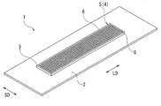
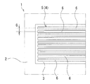
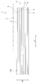
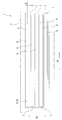
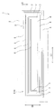
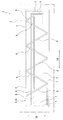
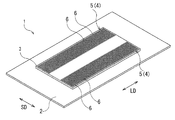
- FIG. 2 is a plan view of the joined body according to the first embodiment of the present invention.
- the perspective view of the joined body of FIG. The elements on larger scale of FIG.
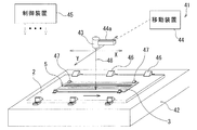
- FIG. 2 is a schematic perspective view of a laser welding device. 4 is a graph showing a relationship between an irradiation area ratio and a buckling stress.
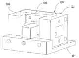
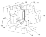
- FIG. 3 is an exploded perspective view of the crushing jig.
- FIG. 6 is a plan view of a joined body according to a second embodiment of the present invention.
- FIG. 10 is a plan view of a joined body according to a third embodiment of the present invention.
- FIG. 14 is a plan view of a joined body according to a fourth embodiment of the present invention.
- FIG. 14 is a plan view of a joined body according to a fifth embodiment of the present invention.
- FIG. 15 is a plan view of a joined body according to a sixth embodiment of the present invention.
- FIG. 16 is a plan view of a joined body according to a seventh embodiment of the present invention.
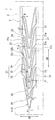
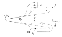
- FIG. 13B is a schematic view of an irradiation pattern in the joined body of FIG. 13A. The top view of the joined body concerning 8th Embodiment of this invention.
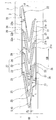
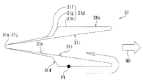
- FIG. 14B is a schematic view of an irradiation pattern in the joined body of FIG. 14A.
- FIG. 15B is a schematic view of an irradiation pattern in the joined body of FIG. 15A.
- FIG. 16B is a schematic view of an irradiation pattern in the joined body of FIG. 16A.
- the joined body 1 includes a blank 2 (first metal member), which is an example of a steel plate, and a reinforcing member 3 (second metal member), which is also an example of a steel plate.
- first metal member which is an example of a steel plate
- second metal member which is also an example of a steel plate.
- the reinforcing material 3 is narrower than the blank material 2.
- the reinforcing material 3 is overlaid on the blank material 2.
- the joined body 1 includes a joined portion 5 constituted by one continuous linear welding mark or welded portion 4.
- the blank 5 and the reinforcing member 3 are joined to each other by the joining portion 5.
- the bonded portion 5 includes ten linear portions 6 (main linear portions) extending in the longitudinal direction LD (first direction) of the reinforcing member 3.
- the joined body 1 of the present embodiment is processed into a B pillar 51 which is an example of a vehicle body structural component by a hot stamp (hot press).
- a hot stamp hot press
- two reinforcing members 3 are joined to the blank 2, and each reinforcing member 3 is joined to a ridge formed by hot stamping.
- only one reinforcing member 3 is illustrated for easy understanding.
- the reinforcing member 3 is fixed to the blank 2 by, for example, laser welding using a laser welding device 41 as shown in FIG.
- the laser welding device 41 includes a table 42, a laser oscillation system 43, a moving device 44, and a control device 45.
- the blank 2 is placed on the upper surface of the table 42 and fixed to the table 42 by a jig 46.
- the reinforcing member 3 stacked on the blank 2 is fixed to the blank 2 by a jig 47.
- the reinforcing material 3 may be fixed to the blank material 2 by temporary fixing welding such as spot welding.
- the blank 2 and the reinforcing member 3 may be fixed to the table 42 by magnetic attraction generated by a magnetic field generated by a magnetic field generator disposed below the table 42.
- the laser oscillation system 43 includes components necessary for generating laser light, such as a laser oscillation element, a drive circuit, and an optical system.
- Laser light 48 is emitted downward from the laser oscillation system 43.
- the moving device 44 moves the laser oscillation system 43.
- the laser oscillation system 43 is fixed to the movable arm 44a of the moving device 44 with the laser beam 48 facing downward.
- the movable arm 44a moves the laser oscillation system 43 in two directions in the horizontal plane, that is, in the X direction and the Y direction, so that the irradiation position of the laser beam 48 moves along the joint portion 5.
- the joining portion 5 that joins the reinforcing member 3 and the blank member 2 is formed by the laser beam 48 applied to the surface of the reinforcing member 3.
- the control device 45 controls the operation of various elements of the laser welding device 41 including the laser oscillation system 43 and the moving device 44 in an integrated manner.
- the present inventors have described a joined body 1 as in the present embodiment in which a reinforcing member 3 is joined to two metal members, that is, a blank material 2, at a joining portion 5 formed by a linear welded portion 4. , Found new findings. Hereinafter, this point will be described.
- the present inventors conducted a test simulating buckling of the web surface when the joined body 1 in which the reinforcing material 3 was welded to the blank material 2 was processed into a B pillar 51 as shown in FIG. 4 by hot stamping.
- the bonded body 1 which is an elongated flat plate is attached to the crushing jig 100 shown in FIGS. 7A to 7C, and the buckling stress of the bonded body 1 when a longitudinal in-plane compressive load is applied by a press machine is measured. did.
- the elements constituting the crushing jig 100 are assembled by bolts (not shown).
- the crushing jig 100 includes a base 101 arranged on a table of a press.
- a lower holding block 102 that holds the lower end side of the joined body 1, a pair of side blocks 103, a rear block 104, and a front block 105 are fixed to the base 101.
- the upper end side of the joined body 1 is held by the upper holding block 106.
- the upper holding block 106 is held by the side blocks 103 so as to be movable only in the vertical direction.
- the front block 105 has a protruding portion 105 a facing the joined body 1.
- the compression load of the press acts on the joined body 1 via the upper holding block 106.
- the direction of the compressive load indicated by the symbol CL shown in FIG. 7C corresponds to the bending moment M (see FIG. 4) acting on the B pillar 51 which is a relatively long member at the time of a vehicle collision.
- FIG. 6 shows the measurement results of the buckling load.
- the horizontal axis shows the ratio of the joint 5 to the area of the reinforcing material 3, that is, the irradiation area ratio, and the vertical axis shows the buckling stress.
- the symbol “ ⁇ ” indicates that the joint portion 5 is composed of a plurality of linear portions 6 extending in the longitudinal direction LD of the reinforcing member 3 as in the present embodiment, that is, the linear portion 6 has a compressive load.
- CL the direction of bending moment M that is expected to act on B pillar 51.
- the symbol “ ⁇ ” indicates that the joint portion 5 is composed of a plurality of linear portions extending in the lateral direction SD (second direction) of the reinforcing member 3, that is, the linear portion 6 has a compressive load.
- a case is shown in which it is provided so as to extend in a direction perpendicular to CL (a direction perpendicular to the direction of the bending moment M that is expected to act on the B pillar 51).
- the joining portion 6 is configured by a line extending in the longitudinal direction of the reinforcing member 3, that is, the direction of the bending moment M that is assumed to act on the B pillar 51. It can be seen that the buckling strength of the B pillar 51 is increased. As described above, the present inventors have found that the strength of a component obtained by processing a joined body has a linear component extending in a direction corresponding to a load in which the joint is expected to act on the component. I found that it could be enhanced.
- the joined portion 5 includes ten straight portions 6 (main straight portions) extending in the longitudinal direction LD of the reinforcing member 3.
- the linear portion 6 has no bent portion, and can be regarded as a substantially geometric straight line.
- the linear portion 6 in the present embodiment is a straight straight line.
- the angle ⁇ formed by the linear portion 6 of the present embodiment with respect to the longitudinal direction LD is 0 degree. That is, the linear portion 6 in the present embodiment is not inclined in the short direction SL.
- the linear portions 6 are provided at regular intervals G in a direction orthogonal to the longitudinal direction LD, that is, in the short direction SD of the reinforcing member 3.
- the angle ⁇ formed by the linear portion 6 in the present embodiment with respect to the longitudinal direction LD is 0 degree.
- the linear portion 6 does not necessarily need to extend parallel to the geometrical longitudinal direction LD. That is, if the angle ⁇ is 0 degrees or more and 15 degrees or less, the buckling strength of the B pillar 51 obtained by processing and manufacturing the joined body 1 can be increased.
- the joining portion 5 includes six linear portions arranged in the transverse direction SD with a constant interval G wider than that of the first embodiment. 6 is provided. Also in this embodiment, when the joined body 1 is processed into the B pillar 51, the total length of the linear portion 6 extending in the direction of the bending moment M occupies 100% of the entire path length of the joined portion 5, and the B pillar 51 can be increased in buckling strength.
- the bonded portion 5 includes six linear portions 6 arranged in the transverse direction SD with a constant interval G therebetween.
- the joint portion 5 includes a plurality of linear portions 7 that respectively connect one ends of a pair of linear portions 6 adjacent to each other in the transverse direction SD, and each linear portion 7 is orthogonal to the longitudinal direction LD.
- Direction that is, in the short direction SD.
- the straight portion 6 and the straight portion 7 form a crank shape.
- the total path length of the joint portion 5 in the present embodiment is the sum of the total length of the linear portions 6 and the total length of the linear portions 7.
- the total length of the linear portion 6 extending in the longitudinal direction LD occupies most of the entire path length of the joint portion 5, that is, about 97%. Therefore, the buckling strength of the B pillar 51 obtained by processing and manufacturing the joined body 1 can be further increased.
- the joint portion 5 extends in the longitudinal direction LD and is connected to seven linear portions 6 arranged in the lateral direction SD, and a short portion that sequentially connects them. And six linear portions 7 extending in the hand direction SD.
- the straight portion 6 and the straight portion 7 form a spiral shape.
- the joined portion 5 extends in the longitudinal direction LD and has five linear portions 6 arranged in the transverse direction SD, and a short portion that sequentially connects them. And four linear portions 7 extending in the hand direction SD.
- the straight portion 6 and the straight portion 7 form a spiral shape.
- two types of inclined linear portions 8, 9 inclined in different directions with respect to the longitudinal direction LD are provided alternately and repeatedly from the innermost end of the spiral shape. Since the joint 5 includes the linear portion 6 extending in the longitudinal direction LD, the buckling strength of the B pillar 51 obtained by processing and manufacturing the joint 1 can be increased.
- the total length of the linear portion 6 extending in the longitudinal direction LD occupies most of the entire path length of the joint portion 5, that is, about 74%. Therefore, the buckling strength of the B pillar 51 obtained by processing and manufacturing the joined body 1 can be further increased.
- the joint portion 5 of the present embodiment includes nine linear portions 6 extending in the longitudinal direction LD and arranged in the lateral direction SD.
- the distance Ge between the linear portions 6 in the end region of the reinforcing member 3 in the short direction SD is smaller than the distance Gc between the linear portions 6 in the central region of the reinforcing member 3 in the short direction SD. That is, the arrangement density of the linear portions 6 in the end region of the reinforcing member 3 in the lateral direction SD is higher than the arrangement density of the linear portions 6 in the central region of the reinforcing member 3 in the lateral direction SD.
- the irradiation pattern 31 in FIG. 13B has two wedge-shaped portions each having a shape that expands in the direction of movement MD, that is, an outer wedge-shaped portion 31b, and an inner wedge disposed inside the outer wedge-shaped portion 31b. And a shape part 31c.
- the outer wedge-shaped portion 31b includes a pair of oblique sides 31d that are inclined with respect to the moving direction MD as a whole, and an arc-shaped distal end 31e that connects these oblique sides 31d.
- Each of the oblique side portions 31d includes a linear first portion 31f having one end connected to the distal end portion 31e, a linear second portion 31g having one end connected to the other end of the first portion 31f, and a second portion 31g.
- Has a third portion 31h having one end connected to the other end of the third portion 31h.
- the angle with respect to the moving direction MD is larger in the order of the second portion 31g, the first portion 31f, and the third portion 31h, and the third portion 31h extends substantially in the same direction as the moving direction MD.
- the length of the second portion 31g is shorter than the first portion 31f and the second portion 31h.
- the inner wedge-shaped portion 31c includes a pair of linear oblique sides 31i that are inclined with respect to the moving direction MD, and an arc-shaped tip 31j that connects these oblique sides 31i.
- the tip 31j of the inner wedge 31c substantially overlaps the tip 31e of the outer wedge 31b.
- Each hypotenuse portion 31i has a linear first portion 31m having one end connected to the distal end portion 31j, a linear second portion 31n having one end connected to the other end of the first portion 31m, and a second portion 31n.
- Has a third portion 31o whose one end is connected to the other end of the third portion 31o.
- Each oblique side 31d of the outer wedge-shaped part 31b is connected to an adjacent one of the oblique sides 31i of the inner wedge-shaped part 31c via an arc-shaped inverted part 31k.
- the joint 5 obtained by the irradiation pattern 31 in FIG. 13B includes a plurality of first linear portions 21 (first main linear portions) and a plurality of second linear portions 22 (second 2 main linear portions).
- the individual first linear portions 21 generally extend in the longitudinal direction LD, but are inclined in the transverse direction SD as a whole to the lower right in the figure.
- the first linear portion 21 includes a first portion 21a extending in the longitudinal direction LD, a second portion 21b having one end connected to the first portion 21a, and a third portion 21c having one end connected to the second portion 21b. .
- the angle ⁇ between the first portion 21a and the longitudinal direction LD is set to 0 degree.
- the angle ⁇ formed by the third portion 21c with respect to the longitudinal direction LD is set to be more than 0 degrees and 15 degrees or less.
- the individual second linear portions 22 generally extend in the longitudinal direction LD, but are inclined as a whole to the right in the transverse direction SD in the figure.
- the second linear portion 22 includes a first portion 22a extending in the longitudinal direction LD, a second portion 22b having one end connected to the first portion 22a, and a third portion 22c having one end connected to the second portion 22b.
- the angle ⁇ between the first portion 22a and the longitudinal direction LD is set to 0 degree.
- the angle ⁇ formed by the third portion 22c with respect to the longitudinal direction LD is set to be more than 0 degrees and 15 degrees or less.
- the first unit 26 is constituted by the pair of first linear portions 21 and one inverting portion 23 (first inverting portion) connecting these.
- the second unit 27 is constituted by the pair of second linear portions 22 and one inverting portion 24 (second inverting portion) connecting these.
- the first unit 26 and the second unit 27 are alternately and repeatedly arranged via a reversing unit 25 (third reversing unit).
- the first linear portion 21 (excluding the second portion 21 b) and the second linear portion 22 (the second linear portion 22) whose angle ⁇ with respect to the longitudinal direction LD is 0 ° or more and 15 ° or less. (Excluding the two portions 22b), so that the buckling strength of the B pillar 51 obtained by processing and manufacturing the joined body 1 can be increased.
- the first linear portion 21 (excluding the second portion 21b) and the second linear portion 22 whose angle ⁇ with respect to the longitudinal direction LD is 0 ° or more and 15 ° or less.
- the total length of the joint portion 5 (excluding the second portion 22b), that is, the total length of the portion extending along the longitudinal direction LD occupies about 77% of the entire path length of the joint portion 5.
- the arrangement density of the first linear portion 21 and the second linear portion 22 in the end region in the lateral direction SD of the reinforcing member 3 depends on the lateral direction of the reinforcing member 3. It is higher than the arrangement density of the first linear portions 21 and the second linear portions 22 in the central region in SD.
- each of the first linear portions 21 and the second linear portions 22 is different from the other first linear portions 21 and the second linear portions 22, and the inverting portions 23 to 25. Does not intersect with any of Therefore, no part of the joint 5 forms a closed figure. Therefore, gas generated at the time of welding for forming the joint portion 5 is discharged to the outside from the mating surface of the blank material 2 and the joint material 3, so that a defect such as a blow hole does not occur at the connection portion.
- the joint 5 shown in FIG. 14A is obtained by moving the irradiation pattern 31 shown in FIG. 14B in the moving direction MD.
- the oblique side portion 31d of the outer wedge-shaped portion 31b has a linear first portion 31f having one end connected to the distal end portion 31e, and a third portion extending substantially in the same direction as the moving direction MD. And a portion 31h.
- the hypotenuse 31i of the inner wedge 31c is linear.
- Other shapes of the irradiation pattern 31 in FIG. 14B are the same as those in FIG. 13B.
- elements common to FIG. 13B are denoted by the same reference numerals.
- one of the pair of first linear portions 21 that constitute the first unit 26 is located outside the reinforcing member 3 in the width direction.
- those located inside the reinforcing member 3 in the width direction have an angle ⁇ with respect to the longitudinal direction LD of more than 0 ° and 15 ° or less. It is a set single straight line.
- the first portion 22a includes a second portion 22b in which the angle ⁇ is greater than 0 degrees and equal to or less than 15 degrees.
- those located in the width direction of the reinforcing member 3 have an angle ⁇ with respect to the longitudinal direction LD of more than 0 ° and 15 ° or less. It is a set single straight line.
- Other shapes of the joint 5 in FIG. 14A are the same as those in FIG. 13A.
- elements common to FIG. 13B are denoted by the same reference numerals.
- the 14A has the first linear portion 21 and the second linear portion 22 in which the angle ⁇ with respect to the longitudinal direction LD is 0 ° or more and 15 ° or less, so that the joined body 1 is processed.
- the buckling strength of the manufactured B pillar 51 can be increased.
- the total length of the first linear portion 21 and the second linear portion 22 whose angle ⁇ with respect to the longitudinal direction LD is 0 ° or more and 15 ° or less is about 96% of the total path length of the joint portion 5. Occupy. With this configuration, the buckling strength of the B pillar 51 obtained by processing and manufacturing the joined body 1 can be further increased.
- the arrangement density of the first linear portion 21 and the second linear portion 22 in the end region of the reinforcing member 3 in the short direction SD is the first straight line in the central region of the reinforcing member 3 in the short direction SD. Since the density is higher than the arrangement density of the linear portion 21 and the second linear portion 22, when the reinforcing material 3 is processed into the B pillar 51, peeling from the blank 2 in the end region in the short direction SD of the reinforcing material 3 is prevented. Can be suppressed or prevented. Further, the individual first linear portions 21 and second linear portions 22 do not intersect with any of the other first linear portions 21 and second linear portions 22 and any of the reversing portions 23 to 25. Gas generated during welding for forming the joint portion 5 can be discharged to the outside.
- the joint 5 shown in FIG. 15A is obtained by moving the irradiation pattern 31 shown in FIG. 15B in the moving direction MD.
- the irradiation pattern 31 shown in FIG. 15B is the same as the irradiation pattern 31 of FIG. 13B except that the oblique side 31i of the inner wedge-shaped portion 31c is linear.
- the angle ⁇ formed by the pair of first linear portions 21 that are located inside the reinforcing member 3 in the width direction among the pair of first linear portions 21 with respect to the longitudinal direction LD is 0 degrees. And a single straight line set at 15 degrees or less. Further, in the joint portion 5 in FIG. 15A, the angle ⁇ formed by the pair of the second linear portions 22 that are located inside the reinforcing member 3 in the width direction among the pair of second linear portions 22 configuring the second unit 27 has an angle ⁇ with respect to the longitudinal direction LD. It is a single straight line set at more than 0 degrees and 15 degrees or less. Except for these points, the joint 5 of FIG. 15A is similar to that of FIG. 13A. In FIG. 15A, elements common to FIG. 13A are denoted by the same reference numerals.
- the 15A has the first linear portion 21 and the second linear portion 22 in which the angle ⁇ with respect to the longitudinal direction LD is 0 ° or more and 15 ° or less, so that the joined body 1 is processed.
- the buckling strength of the manufactured B pillar 51 can be increased. Further, the total length of the first linear portion 21 and the second linear portion 22 whose angle ⁇ with respect to the longitudinal direction LD is 0 ° or more and 15 ° or less is about 89% of the total path length of the joint portion 5. Occupy. With this configuration, the buckling strength of the B pillar 51 obtained by processing and manufacturing the joined body 1 can be further increased.
- the arrangement density of the first linear portion 21 and the second linear portion 22 in the end region of the reinforcing member 3 in the short direction SD is the first straight line in the central region of the reinforcing member 3 in the short direction SD. Since the density is higher than the arrangement density of the linear portion 21 and the second linear portion 22, when the reinforcing material 3 is processed into the B pillar 51, peeling from the blank 2 in the end region in the short direction SD of the reinforcing material 3 is prevented. Can be suppressed or prevented. Further, the individual first linear portions 21 and second linear portions 22 do not intersect with any of the other first linear portions 21 and second linear portions 22 and any of the reversing portions 23 to 25. Gas generated during welding for forming the joint portion 5 can be discharged to the outside.
- (Tenth embodiment) 16A is obtained by moving the irradiation pattern 31 in the moving direction MD similar to that of FIG. 15B, as shown in FIG. 16B.
- the joint 5 of FIG. 16A has an intersection 28 where the first linear portion 21 overlaps the inversion portion 23, and an intersection 29 where the second linear portion 22 overlaps the inversion portion 24, except for the point shown in FIG.
- It is similar to that of 16A includes the first linear portion 21 and the second linear portion 22 whose angle ⁇ with respect to the longitudinal direction LD is 0 ° or more and 15 ° or less, and thus is obtained by processing the joined body 1. Buckling strength of the B pillar 51 can be increased.
- the total length of the first linear portion 21 and the second linear portion 22 whose angle ⁇ with respect to the longitudinal direction LD is 0 ° or more and 15 ° or less is about 88% of the total path length of the joint portion 5 Therefore, the buckling strength of the B pillar 51 obtained by processing the joined body 1 can be further increased. Further, since the arrangement density of the first linear portion 21 and the second linear portion 22 in the end region of the reinforcing member 3 in the short direction SD is high, when the joint 1 is processed into the B pillar 51, The peeling of the material 3 from the blank material 2 can be suppressed or prevented.
- the short direction SD of the first linear portion 21 and the second linear portion 22 is used. Is preferably 15 mm or less.
- the ratio of the total length of the linear portion extending in the longitudinal direction LD that is, the angle ⁇ being equal to or greater than 0 degree and equal to or less than 15 degrees, to the entire path length of the joint portion 5 is equal to the longitudinal length of the reinforcing member 3. This is a numerical value when the ratio between the dimension in the direction LD and the dimension in the lateral direction SD is 6: 1. Further, in the seventh to tenth embodiments, the ratio of the total length of the linear portion extending in the longitudinal direction LD to the entire path length of the joint 5 is the dimension of the reinforcing member 3 in the short direction SD, that is, the reinforcing member 3 This is a numerical value when the width is 40 mm.
- the size of the reinforcing member 3 is not limited to these, and can be changed as appropriate.
- the ratio of the total length of the linear portion extending in the longitudinal direction LD to the total path length of the joint 5 is equal to or more than 74% in accordance with the dimensions of the reinforcing member 3 in the longitudinal direction LD and the transverse direction SD. It is similarly changed to be 97% or less.
- one joint 5 is provided for one reinforcing member 3.
- a plurality of joints 5 may be provided for one reinforcing member 3.
- each joint portion 5 is the same as or similar to that of the first embodiment (see FIGS. 1 to 3), and includes a plurality of linear portions 6 extending in the longitudinal direction LD.
- the individual joints 5 may be the same as or similar to those of the second to tenth embodiments.
- the total length of the joints 5 having the total length of the linear portions extending in the longitudinal direction LD is provided for each individual joint 5.
- the ratio to the path length is set to 74% or more and 97% or less.
Landscapes
- Engineering & Computer Science (AREA)
- Physics & Mathematics (AREA)
- Mechanical Engineering (AREA)
- Optics & Photonics (AREA)
- Plasma & Fusion (AREA)
- Thermal Sciences (AREA)
- Chemical & Material Sciences (AREA)
- Combustion & Propulsion (AREA)
- Transportation (AREA)
- Body Structure For Vehicles (AREA)
- Laser Beam Processing (AREA)
Abstract
接合体1は、第1金属部材2と第2金属部材3とが接合された線状の溶接部4により構成された接合部5を備える。接合部5は、接合体1を加工して得られる部品に作用することが想定される荷重に対応した方向である第1方向LDに沿って延びる直線状である、主直線状部21を備える。主直線状部21は、接合部5のうち前記第1方向となす角度が0度以上15度以下の部分である。接合部5は、第1方向LDと交差する方向である第2方向SDに間隔をあけて並べられた複数の主直線状部分を備える。
Description
本発明は、接合体に関する。
特許文献1,2には、2つの金属部材、すなわち第1金属部材と第2金属部材をレーザ溶接によって接合することで製造される接合体が開示されている。特許文献1には、レーザ溶接の溶接痕ないし溶接部によって構成された接合部が、一対又は複数対の互いに平行な直線であることが開示されている。また、特許文献2には、接合部が連続して配置された複数のC字状部を有し、隣接するC状部の一部が重なることが開示されている。
特許文献1,2に開示されたものを含め、従来のこの種の接合体では、特定の形状の部品に加工した後の強度について考慮されてない。例えば、この種の接合体をホットスタンプ(熱間プレス)で車体構造部品に加工した場合に、想定される荷重(例えば衝突時に作用する荷重)に対し、どのような態様の接合部が当該車体構造部品の強度を高め得るか、考慮されていない。
本発明は、部品に加工した後の強度を高め得る接合部を有する接合体を提供することを課題とする。
本発明者らは、重ねられた2個の金属部材を、線状の溶接部によって構成された接合部で接合した接合体について、新たな知見を見出した。具体的には、本発明者らは、このような接合体を加工して得られる部品の強度は、接合部が当該部品に作用することが想定される荷重に対応した方向に延びる直線状成分が有することで高め得ることを見出した。例えば、このような接合体を加工して得られる比較的長尺な部品に曲げモーメントが作用する場合、接合部が当該曲げモーメンの方向に延びる直線状成分有することで、当該部品の座屈強度が高められることが見出された。本発明は、かかる新たな知見に基づく。
本発明の一態様は、第1金属部材と、前記第1金属部材に重ねられた第2金属部材と、前記第1金属部材と前記第2金属部材とが接合された線状の溶接部により構成された接合部とを備えた接合体であって、前記接合部は、前記接合体を加工して得られる部品に作用することが想定される荷重に対応した方向である第1方向に沿って延びる直線状である、主直線状部を備え、前記主直線状部は、前記接合部のうち前記第1方向となす角度が0度以上15度以下の部分であり、前記接合部は、前記第1方向と交差する方向である第2方向に間隔をあけて並べられた複数の前記主直線状部分を備える、接合体を提供する。
接合部は、接合体を加工して得られる部品に作用することが想定される荷重に対応した方向である第1方向に沿って延びる直線状部、つまり主直線状部を備える。そのため、部品に加工した後の強度を接合部によって高めることができる。
接合体を加工して得られる部品の強度を高めるためには、前記第2方向に互いに隣接する一対の前記主直線状部の前記第2方向の間隔は、15mm以下であってもよい。
前記主直線状部の総長さは、前記接合部の全経路長の74%以上97%以下に設定できる。
接合部の大部分を主直線状部が占めることで、部品に加工した後の強度を接合部によってさらに高めることができる。
前記主直線状部は、前記第1方向と交差する方向である第2方向の一つの向きに全体として傾いた、複数の第1主直線状部と、前記2方向の前記向きとは逆向きに全体として傾いた、複数の第2主直線状部とを含み、前記接合部は、第1反転部を介して互いに接続された一対の前記第1主直線状部により構成された複数の第1ユニットと、第2反転部を介して互いに接続された一対の前記第2主直線状部により構成された複数の第2ユニットとを備え、前記第1ユニットと前記第2ユニットが第3反転部を介して交互に配置されていてもよい。
接合体を加工して得られる部品の強度を高めるためには、前記第2方向に互いに隣接する一対の前記第1及び第2主直線状部の前記第2方向の間隔は、15mm以下であってもよい。
前記第2金属部材の前記第2方向での端部領域における、前記主直線状部の前記第2方向の配置密度は、前記第2金属部材の前記第2方向での中央領域における、前記主直線状部の前記第2方向の配置密度よりも高くてもよい。
この構成により、接合体をプレス加工する際に第2金属部材の端部領域に作用する力により、第2金属部材の端部領域において、第2金属部材の第1金属部材からの剥離が生じるのを抑制ないし防止できる。
本発明に係る接合体によれば、部品に加工した後の強度を接合部によって高めることができる。
(第1実施形態)
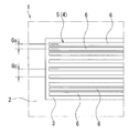
図1から図3は、本発明の第1実施形態に係る接合体1を示す。この接合体1は、鋼板の一例であるブランク材2(第1金属部材)と、同様に鋼板の一例である補強材3(第2金属部材)とを備える。本実施形態では、補強材3はブランク材2よりも幅狭である。
図1から図3は、本発明の第1実施形態に係る接合体1を示す。この接合体1は、鋼板の一例であるブランク材2(第1金属部材)と、同様に鋼板の一例である補強材3(第2金属部材)とを備える。本実施形態では、補強材3はブランク材2よりも幅狭である。
補強材3はブランク材2に重ねられている。接合体1は、連続する1本の線状の溶接痕ないし溶接部4によって構成された接合部5を備える。接合部5によって、ブランク材2と補強材3とが互いに接合されている。本実施形態の接合体1では、接合部5は補強材3の長手方向LD(第1方向)に延びる10個の直線状部6(主直線状部)を備える。
併せて図4を参照すると、本実施形態の接合体1は、ホットスタンプ(熱間プレス)によって車体構造部品の一例であるBピラー51に加工される。図4では、2枚の補強材3がブランク材2の接合されており、個々の補強材3はホットスタンプによって形成される稜線部に接合されている。図4以外の図面においては、理解を容易にするため、1枚の補強材3のみが図示されている。
補強材3は、例えば図5に示すようなレーザ溶接装置41を使用したレーザ溶接によって、ブランク材2に固定される。レーザ溶接装置41は、テーブル42、レーザ発振系43、移動装置44、及び制御装置45を備える。
ブランク材2はテーブル42の上面に載置され、治具46によってテーブル42に固定される。ブランク材2に重ねられた補強材3は、治具47によってブランク材2に固定される。補強材3は、スポット溶接のような仮止めの溶接によってブランク材2に固定されてもよい。また、テーブル42の下方に配置した磁界発生装置が発生する磁界による磁気的吸引力によって、ブランク材2と補強材3をテーブル42に対して固定してもよい。
レーザ発振系43は、レーザ発振素子、駆動回路、光学系等のレーザ光の生成に必要な要素を備える。レーザ発振系43から下向きにレーザ光48が出射される。
移動装置44は、レーザ発振系43を移動させる。移動装置44が備える可動アーム44aに、レーザ光48が下向きとなる姿勢でレーザ発振系43が固定されている。可動アーム44aはレーザ光48の照射位置が接合部5に沿って移動するように、レーザ発振系43を水平面内の2方向、つまりX方向とY方向に移動させる。補強材3の表面に照射されるレーザ光48によって、補強材3とブランク材2を接合する接合部5が形成される。
制御装置45は、レーザ発振系43及び移動装置44を含む、レーザ溶接装置41の種々の要素の動作を統括的に制御する。
本発明者らは、重ねられた2個の金属部材、つまりブランク材2に補強材3を線状の溶接部4によって構成された接合部5で接合した本実施形態のような接合体1について、新たな知見を見出した。以下、この点について説明する。
本発明者らは、ブランク材2に補強材3を溶接した接合体1をホットスタンプによって図4に示すようなBピラー51に加工した場合のウェブ面の座屈を模擬した試験を行った。この試験では、細長い平板である接合体1を図7A~7Cに示す圧壊治具100に取り付け、プレス機によって長手方向の面内圧縮荷重を加えた場合の、接合体1の座屈応力を測定した。
圧壊治具100を構成する要素は、図示しないボルトによって組み立てられる。圧壊治具100は、プレス機のテーブル上に配置されるベース101を備える。ベース101には、接合体1の下端側を保持する下側保持ブロック102、一対の側方ブロック103、後方ブロック104、及び前方ブロック105が固定されている。接合体1の上端側は上側保持ブロック106によって保持される。上側保持ブロック106は、側方ブロック103によって上下方向にのみ移動可能に保持されている。前方ブロック105は接合体1に臨む突出部105aを備える。プレス機の圧縮荷重は、上側保持ブロック106を介して接合体1に作用する。図7Cにおいて示す符号CLで示す圧縮荷重の方向は、車両の衝突時に比較的長尺な部材であるBピラー51に対して作用する曲げモーメントM(図4参照)と対応している。
図6は座屈荷重の測定結果を示し、横軸は補強材3の面積に対して接合部5が示す割合、つまり照射面積率を示し、縦軸は座屈応力を示す。図6において、記号「■」は、本実施形態のように接合部5が補強部材3の長手方向LDに延びる複数の直線状部6で構成されている場合、つまり直線状部6が圧縮荷重CLの方向(Bピラー51に作用することが想定される曲げモーメントMの方向)に延びるように設けられている場合を示す。また、同図において、記号「◆」は接合部5が補強部材3の短手方向SD(第2方向)に延びる複数の直線状部で構成されている場合、つまり直線状部6が圧縮荷重CLと直交する方向(Bピラー51に作用することが想定される曲げモーメントMの方向と直交する方向)に延びるように設けられている場合を示す。
図6のグラフから、本実施形態のように、接合部6が補強材3の長手方向、つまりBピラー51に作用することが想定される曲げモーメントMの方向に延びる線で構成されることで、Bピラー51の座屈強度が高められていることが分かる。このように、本発明者らは、接合体を加工して得られる部品の強度は、接合部が当該部品に作用することが想定される荷重に対応した方向に延びる直線状成分を有することで高め得ることを見出した。
また、図6のグラフから、接合部6が補強材3の長手方向に延びる線で構成されている場合、照射面積率が高いほど、座屈応力が高いことが分かる。このように、本発明者は、部品に作用することが想定される荷重に対応した方向に延びる直線状成分を接合部が有する場合、そのような直線状成分が接合部に占める割合が高い程、より効果的に接合体を加工して得られる部品の強度を高め得ることを見出した。
図1から図3を参照すると、前述のように、本実施形態の接合体1では、接合部5は補強材3の長手方向LDに延びる10個の直線状部6(主直線状部)を備える。本実施形態では、直線状部6は曲り部を有しておらず、実質的に幾何学的な直線とみなし得る。言い換えれば、本実施形態における直線状部6は、真っ直ぐな直線状である。本実施形態の直線状部6は、長手方向LDに対してなす角度θが0度である。つまり、本実施形態における直線状部6は、短手方向SLに傾いていない。また、直線状部6は、長手方向LDと直交する方向、つまり補強材3の短手方向SDに一定の間隔Gをあけて設けられている。
本実施形態の接合体1をホットスタンプによってBピラー51に加工した場合、接合部5を構成する複数の直線状部6はすべて、曲げモーメントMの方向に延びている。つまり、本実施形態では、曲げモーメントMの方向に延びる直線状部6の総長さ(個々の直線状部6の長さの総和)は、接合部5の全経路長の100%を占めている。この構成により、接合体1を加工して製造して得られたBピラー51の座屈強度を高めることができる。
加工により得られるBピラー51の座屈強度を高めるためには、直線状部6間の間隔Gは15mm以下に設定することが好ましい。
前述のように本実施形態における直線状部6が長手方向LDに対してなす角度θは0度である。しかし、直線状部6は幾何学的な長手方向LDに対して平行に延びている必要は必ずしもない。つまり、角度θが0度以上15度以下であれば、接合体1を加工して製造して得られたBピラー51の座屈強度を高めることができる。
(第2実施形態)
図8を参照すると、本実施形態の接合体1では、接合部5は、第1実施形態の場合よりも広い一定の間隔Gをあけて短手方向SDに配置された6個の直線状部6を備える。本実施形態においても、接合体1をBピラー51に加工した場合に曲げモーメントMの方向に延びている直線状部6の総長さが接合部5の全経路長の100%を占め、Bピラー51の座屈強度を高めることができる。
図8を参照すると、本実施形態の接合体1では、接合部5は、第1実施形態の場合よりも広い一定の間隔Gをあけて短手方向SDに配置された6個の直線状部6を備える。本実施形態においても、接合体1をBピラー51に加工した場合に曲げモーメントMの方向に延びている直線状部6の総長さが接合部5の全経路長の100%を占め、Bピラー51の座屈強度を高めることができる。
(第3実施形態)
図9を参照すると、本実施形態の接合体1では、接合部5は、一定の間隔Gをあけて短手方向SDに配置された6個の直線状部6を備える。また、接合部5は、短手方向SDに互いに隣接する一対の直線状部6の一端をそれぞれ接続する、複数の直線状部7を備え、個々の直線状部7は長手方向LDと直交する方向、つまり短手方向SDに延びている。直線状部6と直線状部7とによって、クランク形状が構成されている。接合部5が長手方向LDに延びる直線状部6を備えることで、接合体1を加工して製造して得られたBピラー51の座屈強度を高めることができる。
図9を参照すると、本実施形態の接合体1では、接合部5は、一定の間隔Gをあけて短手方向SDに配置された6個の直線状部6を備える。また、接合部5は、短手方向SDに互いに隣接する一対の直線状部6の一端をそれぞれ接続する、複数の直線状部7を備え、個々の直線状部7は長手方向LDと直交する方向、つまり短手方向SDに延びている。直線状部6と直線状部7とによって、クランク形状が構成されている。接合部5が長手方向LDに延びる直線状部6を備えることで、接合体1を加工して製造して得られたBピラー51の座屈強度を高めることができる。
本実施形態における接合部5の全経路長は、直線状部6の総長さと直線状部7の総長さの和である。長手方向LDに延びる直線状部6の総長さが接合部5の全経路長の大部分、つまり約97%を占めている。そのため、接合体1を加工して製造して得られたBピラー51の座屈強度をさらに高めることができる。
(第4実施形態)
図10を参照すると、本実施形態の接合部5では、接合部5は、長手方向LDに延びており短手方向SDに配置された7個の直線状部6と、これを順次接続する短手方向SDに延びる6個の直線状部7とを備える。直線状部6と直線状部7とによって、渦巻き形状が構成されている。接合部5が長手方向LDに延びる直線状部6を備えることで、接合体1を加工して製造して得られたBピラー51の座屈強度を高めることができる。また、長手方向LDに延びる直線状部6の総長さが接合部5の全経路長の大部分、つまり約92%を占めている。そのため、接合体1を加工して製造して得られたBピラー51の座屈強度をさらに高めることができる。
図10を参照すると、本実施形態の接合部5では、接合部5は、長手方向LDに延びており短手方向SDに配置された7個の直線状部6と、これを順次接続する短手方向SDに延びる6個の直線状部7とを備える。直線状部6と直線状部7とによって、渦巻き形状が構成されている。接合部5が長手方向LDに延びる直線状部6を備えることで、接合体1を加工して製造して得られたBピラー51の座屈強度を高めることができる。また、長手方向LDに延びる直線状部6の総長さが接合部5の全経路長の大部分、つまり約92%を占めている。そのため、接合体1を加工して製造して得られたBピラー51の座屈強度をさらに高めることができる。
(第5実施形態)
図11を参照すると、本実施形態の接合体1では、接合部5は、長手方向LDに延びており短手方向SDに配置された5個の直線状部6と、これらを順次接続する短手方向SDに延びる4個の直線状部7とを備える。直線状部6と直線状部7とによって、渦巻き形状が構成されている。また、接合部5では、長手方向LDに対して異なる向きに傾斜する2種類の傾斜直線状部8,9が、渦巻き形状の最内端から交互に繰り返して設けられている。接合部5が長手方向LDに延びる直線状部6を備えることで、接合体1を加工して製造して得られたBピラー51の座屈強度を高めることができる。長手方向LDに延びる直線状部6の総長さが接合部5の全経路長の、大部分、つまり約74%を占めている。そのため、接合体1を加工して製造して得られたBピラー51の座屈強度をさらに高めることができる。
図11を参照すると、本実施形態の接合体1では、接合部5は、長手方向LDに延びており短手方向SDに配置された5個の直線状部6と、これらを順次接続する短手方向SDに延びる4個の直線状部7とを備える。直線状部6と直線状部7とによって、渦巻き形状が構成されている。また、接合部5では、長手方向LDに対して異なる向きに傾斜する2種類の傾斜直線状部8,9が、渦巻き形状の最内端から交互に繰り返して設けられている。接合部5が長手方向LDに延びる直線状部6を備えることで、接合体1を加工して製造して得られたBピラー51の座屈強度を高めることができる。長手方向LDに延びる直線状部6の総長さが接合部5の全経路長の、大部分、つまり約74%を占めている。そのため、接合体1を加工して製造して得られたBピラー51の座屈強度をさらに高めることができる。
(第6実施形態)
図12を参照すると、本実施形態の接合部5は、長手方向LDに延びており短手方向SDに配置された9個の直線状部6を備える。補強材3の短手方向SDでの端部領域における直線状部6間の間隔Geは、補強材3の短手方向SDでの中央領域における直線状部6間の間隔Gcよりも狭い。つまり、補強材3の短手方向SDでの端部領域における直線状部6の配置密度は、補強材3の短手方向SDでの中央領域における直線状部6の配置密度よりも高い。この構成により、接合体1をホットスタンプによりBピラー51に加工する際、補強材3の短手方向SDの端部領域に作用する力(図4において符号Fで概念的に示す。)により、補強材3の短手方向SDの端部領域においてブランク材2からの剥離が生じるのを抑制ないし防止できる。
図12を参照すると、本実施形態の接合部5は、長手方向LDに延びており短手方向SDに配置された9個の直線状部6を備える。補強材3の短手方向SDでの端部領域における直線状部6間の間隔Geは、補強材3の短手方向SDでの中央領域における直線状部6間の間隔Gcよりも狭い。つまり、補強材3の短手方向SDでの端部領域における直線状部6の配置密度は、補強材3の短手方向SDでの中央領域における直線状部6の配置密度よりも高い。この構成により、接合体1をホットスタンプによりBピラー51に加工する際、補強材3の短手方向SDの端部領域に作用する力(図4において符号Fで概念的に示す。)により、補強材3の短手方向SDの端部領域においてブランク材2からの剥離が生じるのを抑制ないし防止できる。
(第7実施形態)
図13Aに示す接合部5は、図13Bに示すレーザ光48の照射位置P1が描く閉図形(照射パターン31)が、補強材3の一端側から他端側に向けて矢印MDで示すように移動することで得られる。
図13Aに示す接合部5は、図13Bに示すレーザ光48の照射位置P1が描く閉図形(照射パターン31)が、補強材3の一端側から他端側に向けて矢印MDで示すように移動することで得られる。
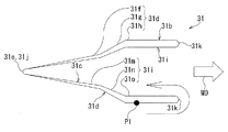
図13Bの照射パターン31は、いずれも移動方向MDの向きに幅が広がる形状を有する2個のくさび形部、つまり外側くさび形部31bと、外側くさび形部31bの内側に配置された内側くさび形部31cとを備える。
外側くさび形部31bは、全体としては移動方向MDに対して傾斜した一対の斜辺部31dと、これらの斜辺部31dを接続する円弧状の先端部31eとを備える。個々の斜辺部31dは、先端部31eに一端が接続された直線状の第1部分31f、第1部分31fの他端に一端が接続された直線状の第2部分31g、及び第2部分31gの他端に一端が接続された第3部分31hを有する。この例では、移動方向MDに対する角度は、第2部分31g、第1部分31f、第3部分31hの順で大きく、第3部分31hは概ね移動方向MDと同方向に延びている。また、この例では、第2部分31gの長さは、第1部分31f及び第2部分31hよりも短い。
内側くさび形部31cは、移動方向MDに対して傾斜している直線状の一対の斜辺部31iと、これらの斜辺部31iを接続する円弧状の先端部31jとを備える。内側くさび形部31cの先端部31jは、外側くさび形部31bの先端部31eと、概ね重なっている。個々の斜辺部31iは、先端部31jに一端が接続された直線状の第1部分31m、第1部分31mの他端に一端が接続された直線状の第2部分31n、及び第2部分31nの他端に一端が接続された第3部分31oを有する。
外側くさび形部31bの個々の斜辺部31dは、内側くさび形部31cの斜辺部31iのうち隣接するものと、円弧状の反転部31kを介して接続されている。
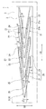
図13Aを併せて参照すると、図13Bの照射パターン31で得られる接合部5は、複数の第1直線状部21(第1主直線状部)と、複数の第2直線状部22(第2主直線状部)とを備える。
個々の第1直線状部21は、概ね長手方向LDに延びているが、短手方向SDに図において右下がりに全体として傾いている。第1直線状部21は、長手方向LDに延びる第1部分21a、第1部分21aに一端が接続された第2部分21b、及び第2部分21bに一端が接続された第3部分21cを備える。第1部分21aの長手方向LDに対してなす角度θは、0度に設定されている。第3部分21cの長手方向LDに対してなす角度θは、0度を上回り15度以下に設定されている。
個々の第2直線状部22は、概ね長手方向LDに延びているが、短手方向SDに図において右上がりに全体として傾いている。第2直線状部22は、長手方向LDに延びる第1部分22a、第1部分22aに一端が接続された第2部分22b、及び第2部分22bに一端が接続された第3部分22cを備える。第1部分22aの長手方向LDに対してなす角度θは、0度に設定されている。第3部分22cの長手方向LDに対してなす角度θは、0度を上回り15度以下に設定されている。
一対の第1直線状部21と、これらを互いに接続する1個の反転部23(第1反転部)とによって、第1ユニット26が構成されている。また、一対の第2直線状部22と、これらを互いに接続する1個の反転部24(第2反転部)とによって、第2ユニット27が構成されている。第1ユニット26と第2ユニット27は反転部25(第3反転部)を介して交互に繰り返して配置されている。
本実施形態の接合部5では、長手方向LDに対してなす角度θが0度以上15度以下である第1直線状部21(第2部分21bを除く)と第2直線状部22(第2部分22bを除く)とを有するので、接合体1を加工して製造して得られたBピラー51の座屈強度を高めることができる。
また、本実施形態の接合部5では、長手方向LDに対してなす角度θが0度以上15度以下である第1直線状部21(第2部分21bを除く)と第2直線状部22(第2部分22bを除く)の総長さ、つまり長手方向LDに沿って延びる部分の総長さが、接合部5の全経路長さの約77%を占めている。この構成により、接合体1を加工して製造して得られたBピラー51の座屈強度をさらに高めることができる。
図13Aを参照すれば明らかなように、補強材3の短手方向SDでの端部領域における第1直線状部21と第2直線状部22の配置密度は、補強材3の短手方向SDでの中央領域における第1直線状部21と第2直線状部22の配置密度よりも高い。この構成により、接合体1をホットスタンプによりBピラー51に加工する際、補強材3の短手方向SDの端部領域に作用する力F(図4参照)により、補強材3の短手方向SDの端部領域においてブランク材2からの剥離が生じるのを抑制ないし防止できる。
図13Aを参照すれば明らかなように、個々の第1直線状部21及び第2直線状部22は、他の第1直線状部21及び第2直線状部22、並びに反転部23~25のいずれとも交差していない。従って、接合部5のいかなる部分も閉図形を構成していない。そのため、接合部5を形成するための溶接時に発生するガスがブランク材2と接合材3の合わせ面から外部に排出されるため、接続部位にブローホール等の欠陥が生じることがない。
(第8実施形態)
図14Aに示す接合部5は、図14Bに示す照射パターン31の移動方向MDへの移動により得られる。
図14Aに示す接合部5は、図14Bに示す照射パターン31の移動方向MDへの移動により得られる。
図14Bの照射パターン31では、外側くさび形部31bの斜辺部31dは、先端部31eに一端が接続された直線状の第1部分31fと、概ね移動方向MDと同方向に延びている第3部分31hとにより構成されている。また、内側くさび形部31cの斜辺部31iは直線状である。図14Bの照射パターン31のその他の形状は図13Bのものと同様である。図14Bにおいて図13Bと共通する要素には、同一の符号を付している。
図14Aを併せて参照すると、図14Bの照射パターン31で得られる接合部5では、第1ユニット26を構成する一対の第1直線状部21のうち補強材3の幅方向外側に位置するものは、長手方向LDに対してなす角度θが0度に設定された第1部分21aと、この角度θが0度を上回り15度以下に設定された第2部分21bとを備える。また、第1ユニット26を構成する一対の第1直線状部21のうち補強材3の幅方向内側に位置するものは、長手方向LDに対してなす角度θが0度を上回り15度以下に設定された単一の直線状である。同様に、第1ユニット27を構成する一対の第2直線状部22のうち補強材3の幅方向外側に位置するものは、長手方向LDに対してなす角度θが0度に設定された第1部分22aと、この角度θが0度を上回り15度以下に設定された第2部分22bとを備える。また、第2ユニット27を構成する一対の第2直線状部22のうち補強材3の幅方向内に位置するものは、長手方向LDに対してなす角度θが0度を上回り15度以下に設定された単一の直線状である。図14Aの接合部5のその他の形状は、図13Aのものと同様である。図14Aにおいて図13Bと共通する要素には、同一の符号を付している。
図14Aの接合部5は、長手方向LDに対してなす角度θが0度以上15度以下である第1直線状部21と第2直線状部22を有するので、接合体1を加工して製造して得られたBピラー51の座屈強度を高めることができる。また、長手方向LDに対してなす角度θが0度以上15度以下である第1直線状部21と第2直線状部22の総長さが、接合部5の全経路長さの約96%を占めている。この構成により、接合体1を加工して製造して得られたBピラー51の座屈強度をさらに高めることができる。また、補強材3の短手方向SDでの端部領域における第1直線状部21と第2直線状部22の配置密度は、補強材3の短手方向SDでの中央領域における第1直線状部21と第2直線状部22の配置密度よりも高いので、Bピラー51に加工する際に、補強材3の短手方向SDの端部領域においてブランク材2からの剥離が生じるのを抑制ないし防止できる。さらに、個々の第1直線状部21及び第2直線状部22は、他の第1直線状部21及び第2直線状部22、並びに反転部23~25のいずれとも交差していないので、接合部5を形成するための溶接時に発生するガスを外部に排出できる。
(第9実施形態)
図15Aに示す接合部5は、図15Bに示す照射パターン31の移動方向MDへの移動により得られる。
図15Aに示す接合部5は、図15Bに示す照射パターン31の移動方向MDへの移動により得られる。
図15Bに示す照射パターン31は、内側くさび形部31cの斜辺部31iが直線状であることを除いて、図13Bの照射パターン31と同様である。
図15Aの接合部5では、第1ユニット26を構成する一対の第1直線状部21のうち補強材3の幅方向内側に位置するものが、長手方向LDに対してなす角度θが0度を上回り15度以下に設定された単一の直線状である。また、図15Aの接合部5では、第2ユニット27を構成する一対の第2直線状部22のうち補強材3の幅方向内側に位置するものが、長手方向LDに対してなす角度θが0度を上回り15度以下に設定された単一の直線状である。これらの点を除いて、図15Aの接合部5は図13Aのものと同様である。図15Aにおいて図13Aと共通する要素には、同一の符号を付している。
図15Aの接合部5は、長手方向LDに対してなす角度θが0度以上15度以下である第1直線状部21と第2直線状部22を有するので、接合体1を加工して製造して得られたBピラー51の座屈強度を高めることができる。また、長手方向LDに対してなす角度θが0度以上15度以下である第1直線状部21と第2直線状部22の総長さが、接合部5の全経路長さの約89%を占めている。この構成により、接合体1を加工して製造して得られたBピラー51の座屈強度をさらに高めることができる。また、補強材3の短手方向SDでの端部領域における第1直線状部21と第2直線状部22の配置密度は、補強材3の短手方向SDでの中央領域における第1直線状部21と第2直線状部22の配置密度よりも高いので、Bピラー51に加工する際に、補強材3の短手方向SDの端部領域においてブランク材2からの剥離が生じるのを抑制ないし防止できる。さらに、個々の第1直線状部21及び第2直線状部22は、他の第1直線状部21及び第2直線状部22、並びに反転部23~25のいずれとも交差していないので、接合部5を形成するための溶接時に発生するガスを外部に排出できる。
(第10実施形態)
図16Aに示す接合部5は、図16Bに示すとおり、図15Bのものと同様の照射パターン31の移動方向MDへの移動により得られる。図16Aの接合部5は、反転部23に第1直線状部21が重なる交差部28と、反転部24に第2直線状部22が重なる交差部29とを備える点を除いて、図15Aのものと同様である。図16Aの接合部5は、長手方向LDに対してなす角度θが0度以上15度以下である第1直線状部21と第2直線状部22を有するので、接合体1の加工により得られるBピラー51の座屈強度を高めることができる。また、長手方向LDに対してなす角度θが0度以上15度以下である第1直線状部21と第2直線状部22の総長さが、接合部5の全経路長さの約88%を占めているので、接合体1の加工により得られるBピラー51の座屈強度をさらに高めることができる。また、補強材3の短手方向SDでの端部領域における第1直線状部21と第2直線状部22の配置密度が高いので、接合体1をBピラー51に加工する際に、補強材3のブランク材2からの剥離を抑制ないし防止できる。
図16Aに示す接合部5は、図16Bに示すとおり、図15Bのものと同様の照射パターン31の移動方向MDへの移動により得られる。図16Aの接合部5は、反転部23に第1直線状部21が重なる交差部28と、反転部24に第2直線状部22が重なる交差部29とを備える点を除いて、図15Aのものと同様である。図16Aの接合部5は、長手方向LDに対してなす角度θが0度以上15度以下である第1直線状部21と第2直線状部22を有するので、接合体1の加工により得られるBピラー51の座屈強度を高めることができる。また、長手方向LDに対してなす角度θが0度以上15度以下である第1直線状部21と第2直線状部22の総長さが、接合部5の全経路長さの約88%を占めているので、接合体1の加工により得られるBピラー51の座屈強度をさらに高めることができる。また、補強材3の短手方向SDでの端部領域における第1直線状部21と第2直線状部22の配置密度が高いので、接合体1をBピラー51に加工する際に、補強材3のブランク材2からの剥離を抑制ないし防止できる。
第7から第10実施形態における接合部5についても、加工により得られるBピラー51の座屈強度を高めるには、第1直線状部21と第2直線状部22のうち、短手方向SDに隣接するものの間隔は15mm以下であることが好ましい。
第1から第6実施形態における、長手方向LDに延びる、つまり角度θが0度以上15度以下である直線状部の総長さの接合部5の全経路長に対する比率は、補強材3の長手方向LDと短手方向SDの寸法の比率が6:1であるときの数値である。また、第7から第10実施形態における、長手方向LDに延びる直線状部の総長さの接合部5の全経路長に対する比率は、補強材3の短手方向SDの寸法、つまり補強材3の幅が40mmである時の数値である。しかし、補強材3の寸法は、これらに限定されず、適宜変更することができる。接合部5の形状は、補強材3の長手方向LDと短手方向SDの寸法に合わせて、長手方向LDに延びる直線状部の総長さの接合部5の全経路長に対する比率が74%以上97%以下となるように、相似的に変更される。
第1から第10実施形態では、1枚の補強材3に対して1個の接合部5が設けられている。しかし、1枚の補強材3に対して、複数の接合部5を設けてもよい。例えば、図17に示す接合体1では、1枚の補強材3に対し、2個の接合部5が設けられている。この例では、個々の接合部5は、第1実施形態(図1から図3参照)のものと同一ないし同様であり、長手方向LDの延びる複数の直線状部6を備える。個々の接合部5は、第2から第10実施形態のものと同一ないし同様であってもよい。図17の例のように1枚の補強材3に対して複数の接合部5を設ける場合、個々の接合部5毎に、長手方向LDに延びる直線状部の総長さの接合部5の全経路長に対する比率が74%以上97%以下に設定される。
1 接合体
2 ブランク材(第1金属部材)
3 補強材(第2金属部材)
4 溶接部
5 接合部
6 直線状部(主直線状部)
7 直線状部
8,9 直線状部
21 第1直線状部
21a 第1部分
21b 第2部分
21c 第3部分
22 第2直線状部
22a 第1部分
22b 第2部分
22c 第3部分
23 反転部(第1反転部)
24 反転部(第2反転部)
25 反転部(第3反転部)
26 第1ユニット
27 第2ユニット
28,29 交差部
31 照射パターン
31b 外側くさび形部
31c 内側くさび形部
31d,31i 斜辺部
31e,31j 先端部
31f,31m 第1部分
31g,31n 第2部分
31h,31o 第3部分
31k 反転部
41 レーザ溶接装置
42 テーブル
43 レーザ発振系
44 移動装置
44a 可動アーム
45 制御装置
46,47 治具
48 レーザ光
51 Bピラー
100 圧壊治具
101 ベース
102 下側保持ブロック
103 側方ブロック
104 後方ブロック
105 前方ブロック
105a 突出部
106 上側保持ブロック
M 曲げモーメント
F 力
LD 長手方向
SD 短手方向
G,Ge,Gc 間隔
θ 角度
MD 照射パターンの移動方向
CL 圧縮荷重
2 ブランク材(第1金属部材)
3 補強材(第2金属部材)
4 溶接部
5 接合部
6 直線状部(主直線状部)
7 直線状部
8,9 直線状部
21 第1直線状部
21a 第1部分
21b 第2部分
21c 第3部分
22 第2直線状部
22a 第1部分
22b 第2部分
22c 第3部分
23 反転部(第1反転部)
24 反転部(第2反転部)
25 反転部(第3反転部)
26 第1ユニット
27 第2ユニット
28,29 交差部
31 照射パターン
31b 外側くさび形部
31c 内側くさび形部
31d,31i 斜辺部
31e,31j 先端部
31f,31m 第1部分
31g,31n 第2部分
31h,31o 第3部分
31k 反転部
41 レーザ溶接装置
42 テーブル
43 レーザ発振系
44 移動装置
44a 可動アーム
45 制御装置
46,47 治具
48 レーザ光
51 Bピラー
100 圧壊治具
101 ベース
102 下側保持ブロック
103 側方ブロック
104 後方ブロック
105 前方ブロック
105a 突出部
106 上側保持ブロック
M 曲げモーメント
F 力
LD 長手方向
SD 短手方向
G,Ge,Gc 間隔
θ 角度
MD 照射パターンの移動方向
CL 圧縮荷重
Claims (6)
- 第1金属部材と、
前記第1金属部材に重ねられた第2金属部材と、
前記第1金属部材と前記第2金属部材とが接合された線状の溶接部により構成された接合部と
を備えた接合体であって、
前記接合部は、前記接合体を加工して得られる部品に作用することが想定される荷重に対応した方向である第1方向に沿って延びる直線状である、主直線状部を備え、
前記主直線状部は、前記接合部のうち前記第1方向となす角度が0度以上15度以下の部分であり、
前記接合部は、前記第1方向と交差する方向である第2方向に間隔をあけて並べられた複数の前記主直線状部分を備える、接合体。 - 前記第2方向に互いに隣接する一対の前記主直線状部の前記第2方向の間隔は、15mm以下である、請求項1に記載の接合体。
- 前記主直線状部の総長さは、前記接合部の全経路長の74%以上97%以下である、請求項1又は請求項2に記載の接合体。
- 前記主直線状部は、
前記第1方向と交差する方向である第2方向の一つの向きに全体として傾いた、複数の第1主直線状部と、
前記2方向の前記向きとは逆向きに全体として傾いた、複数の第2主直線状部とを含み、
前記接合部は、
第1反転部を介して互いに接続された一対の前記第1主直線状部により構成された複数の第1ユニットと、
第2反転部を介して互いに接続された一対の前記第2主直線状部により構成された複数の第2ユニットと
を備え、
前記第1ユニットと前記第2ユニットが第3反転部を介して交互に配置されている、請求項1又は請求項2に記載の接合体。 - 前記第2方向に互いに隣接する一対の前記第1及び第2主直線状部の前記第2方向の間隔は、15mm以下である、請求項4に記載の接合体。
- 前記第2金属部材の前記第2方向での端部領域における、前記主直線状部の前記第2方向の配置密度は、前記第2金属部材の前記第2方向での中央領域における、前記主直線状部の前記第2方向の配置密度よりも高い、請求項1又は請求項2に記載の接合体。
Priority Applications (3)
| Application Number | Priority Date | Filing Date | Title |
|---|---|---|---|
| EP19831228.2A EP3819066A4 (en) | 2018-07-06 | 2019-06-03 | LIAISON |
| CN201980045365.7A CN112399902A (zh) | 2018-07-06 | 2019-06-03 | 接合体 |
| US17/256,090 US20210269098A1 (en) | 2018-07-06 | 2019-06-03 | Joined body |
Applications Claiming Priority (2)
| Application Number | Priority Date | Filing Date | Title |
|---|---|---|---|
| JP2018-129355 | 2018-07-06 | ||
| JP2018129355A JP2020006401A (ja) | 2018-07-06 | 2018-07-06 | 接合体 |
Publications (1)
| Publication Number | Publication Date |
|---|---|
| WO2020008772A1 true WO2020008772A1 (ja) | 2020-01-09 |
Family
ID=69060650
Family Applications (1)
| Application Number | Title | Priority Date | Filing Date |
|---|---|---|---|
| PCT/JP2019/022014 Ceased WO2020008772A1 (ja) | 2018-07-06 | 2019-06-03 | 接合体 |
Country Status (5)
| Country | Link |
|---|---|
| US (1) | US20210269098A1 (ja) |
| EP (1) | EP3819066A4 (ja) |
| JP (1) | JP2020006401A (ja) |
| CN (1) | CN112399902A (ja) |
| WO (1) | WO2020008772A1 (ja) |
Cited By (2)
| Publication number | Priority date | Publication date | Assignee | Title |
|---|---|---|---|---|
| JP2025523147A (ja) * | 2022-07-29 | 2025-07-17 | ヌオーヴォ・ピニォーネ・テクノロジー・ソチエタ・レスポンサビリタ・リミタータ | シュラウド付きインペラを製造するための方法 |
| US12629774B2 (en) * | 2022-07-29 | 2026-05-19 | Nuovo Pignone Tecnologie—S.R.L. | Method for manufacturing a shrouded impeller |
Families Citing this family (4)
| Publication number | Priority date | Publication date | Assignee | Title |
|---|---|---|---|---|
| JP7063930B2 (ja) * | 2020-03-13 | 2022-05-09 | フタバ産業株式会社 | 成形品の製造方法及び成形品 |
| CN114475796B (zh) * | 2022-02-11 | 2023-04-25 | 湖州师范学院 | 一种提高车辆b柱抗型变强度的方法 |
| DE102022106540A1 (de) * | 2022-03-21 | 2023-09-21 | Audi Aktiengesellschaft | Verfahren zum Laserstrahlschweißen |
| CN117444391A (zh) * | 2023-09-25 | 2024-01-26 | 海目星激光科技集团股份有限公司 | 接线盒激光焊接方法、装置、设备及存储介质 |
Citations (3)
| Publication number | Priority date | Publication date | Assignee | Title |
|---|---|---|---|---|
| JP2001507993A (ja) | 1997-01-14 | 2001-06-19 | コスマ パワーレーザーズ リミテッド | テイラードブランク |
| JP2014015206A (ja) | 2010-09-16 | 2014-01-30 | Nippon Steel & Sumitomo Metal | 成形部材およびその製造方法 |
| JP2016064725A (ja) * | 2014-09-24 | 2016-04-28 | 富士重工業株式会社 | 車体骨格構造、及びその製造方法 |
Family Cites Families (17)
| Publication number | Priority date | Publication date | Assignee | Title |
|---|---|---|---|---|
| US4223201A (en) * | 1978-12-14 | 1980-09-16 | United Technologies Corporation | Laser welding apparatus for shipyard panel shops |
| DE3478906D1 (en) * | 1983-04-20 | 1989-08-17 | British Shipbuilders Eng | Laser-beamwelding |
| DE59700614D1 (de) * | 1997-02-08 | 1999-12-02 | Volkswagen Ag | Umformteil mit einer bereichsweise ausgebildeten Mehrfachblechstruktur |
| EP2537626B1 (en) * | 2004-05-18 | 2019-06-26 | Kawasaki Jukogyo Kabushiki Kaisha | Body structure for rolling stock |
| DE102009016805B4 (de) * | 2009-04-09 | 2014-04-03 | Alanod Gmbh & Co. Kg | Verfahren zum Laserverschweißen eines Verbundmaterials mit einem Bauteil |
| DE102011101700A1 (de) * | 2010-12-21 | 2012-06-21 | Sitech Sitztechnik Gmbh | Fahrzeugsitz mit laserverfestigten Bereichen |
| ES2658222T3 (es) * | 2012-11-29 | 2018-03-08 | Nippon Steel & Sumitomo Metal Corporation | Método para la formación de junta de soldadura por arco en ángulo y junta de soldadura por arco en ángulo |
| JP6091974B2 (ja) * | 2013-04-16 | 2017-03-08 | 株式会社神戸製鋼所 | 溶接物の製造方法、溶接方法、溶接装置 |
| MX387869B (es) * | 2014-02-06 | 2025-03-19 | Nippon Steel Corp | Metodo de soldadura por solapado, union de solapa, metodo de produccion para union de solapa, y parte automotriz. |
| DE102014101907A1 (de) * | 2014-02-14 | 2015-08-20 | Thyssenkrupp Ag | Metallblech mit lokaler metallischer Verstärkung und Verfahren zu dessen Herstellung |
| GB2532001B (en) * | 2014-10-24 | 2017-09-27 | Gkn Aerospace Sweden Ab | Crack stopper for welds |
| CN104527805A (zh) * | 2014-12-17 | 2015-04-22 | 无锡朗贤汽车组件研发中心有限公司 | 车辆的b柱及制造方法 |
| CN205421229U (zh) * | 2016-03-25 | 2016-08-03 | 何晓婷 | 一种加筋热熔连接的土工格室 |
| JP2018086664A (ja) * | 2016-11-28 | 2018-06-07 | 武藤工業株式会社 | 溶接装置、溶接方法、三次元造形装置、及び三次元造形方法 |
| CN106903430A (zh) * | 2017-03-17 | 2017-06-30 | 敏实汽车技术研发有限公司 | 一种汽车门框a柱板、b柱板、c柱板焊接方法 |
| JP6994324B2 (ja) * | 2017-08-31 | 2022-01-14 | 株式会社神戸製鋼所 | 接合体の製造方法および製造装置 |
| JP6966977B2 (ja) * | 2018-06-20 | 2021-11-17 | 株式会社神戸製鋼所 | レーザ溶接方法及びレーザ溶接装置 |
-
2018
- 2018-07-06 JP JP2018129355A patent/JP2020006401A/ja active Pending
-
2019
- 2019-06-03 EP EP19831228.2A patent/EP3819066A4/en not_active Withdrawn
- 2019-06-03 WO PCT/JP2019/022014 patent/WO2020008772A1/ja not_active Ceased
- 2019-06-03 CN CN201980045365.7A patent/CN112399902A/zh active Pending
- 2019-06-03 US US17/256,090 patent/US20210269098A1/en not_active Abandoned
Patent Citations (3)
| Publication number | Priority date | Publication date | Assignee | Title |
|---|---|---|---|---|
| JP2001507993A (ja) | 1997-01-14 | 2001-06-19 | コスマ パワーレーザーズ リミテッド | テイラードブランク |
| JP2014015206A (ja) | 2010-09-16 | 2014-01-30 | Nippon Steel & Sumitomo Metal | 成形部材およびその製造方法 |
| JP2016064725A (ja) * | 2014-09-24 | 2016-04-28 | 富士重工業株式会社 | 車体骨格構造、及びその製造方法 |
Non-Patent Citations (1)
| Title |
|---|
| See also references of EP3819066A4 |
Cited By (3)
| Publication number | Priority date | Publication date | Assignee | Title |
|---|---|---|---|---|
| JP2025523147A (ja) * | 2022-07-29 | 2025-07-17 | ヌオーヴォ・ピニォーネ・テクノロジー・ソチエタ・レスポンサビリタ・リミタータ | シュラウド付きインペラを製造するための方法 |
| US20250332663A1 (en) * | 2022-07-29 | 2025-10-30 | Nuovo Pignone Tecnologie -S.R.L. | Method for manufacturing a shrouded impeller |
| US12629774B2 (en) * | 2022-07-29 | 2026-05-19 | Nuovo Pignone Tecnologie—S.R.L. | Method for manufacturing a shrouded impeller |
Also Published As
| Publication number | Publication date |
|---|---|
| US20210269098A1 (en) | 2021-09-02 |
| EP3819066A1 (en) | 2021-05-12 |
| CN112399902A (zh) | 2021-02-23 |
| EP3819066A4 (en) | 2022-04-13 |
| JP2020006401A (ja) | 2020-01-16 |
Similar Documents
| Publication | Publication Date | Title |
|---|---|---|
| JP2020006401A (ja) | 接合体 | |
| JP5382233B1 (ja) | パネル接合構造 | |
| CN102476248A (zh) | 嵌板结构体的制造方法 | |
| JP4359291B2 (ja) | 被接合部材 | |
| JP7173940B2 (ja) | 構造部材 | |
| JP5266113B2 (ja) | 振動溶着パレット | |
| JP2007038231A (ja) | 直交関係で組み付ける角パイプ組付構造 | |
| JPH11239890A (ja) | 溶接構造 | |
| JP2000248574A (ja) | 作業機械の作業腕構造 | |
| JP6382363B2 (ja) | 荷重支持部材 | |
| JP2016225001A (ja) | 薄板回路基板、フレキシャー、及び溶接方法 | |
| JP6124702B2 (ja) | 座屈拘束ブレース | |
| JP5090387B2 (ja) | リードフレーム | |
| JP3960116B2 (ja) | 天板又は底板の製造方法及びそれらを用いた箱体の製造方法 | |
| JP5216057B2 (ja) | 乗客コンベア | |
| KR102231825B1 (ko) | 웨이브 스프링 | |
| JP2008006472A (ja) | レーザ溶接方法及び鉄道車両 | |
| JP7832037B2 (ja) | 接合部材、接合部材の製造方法、柱と梁との接合構造 | |
| WO2021070608A1 (ja) | 板材連結機構 | |
| JP6871989B2 (ja) | 構造物の柱脚構造およびベースプレート | |
| WO2021220326A1 (ja) | 樹脂部材の継手構造、電気機器の樹脂筐体、及びレーザ溶着方法 | |
| JP2014100718A (ja) | 補強方法および補強構造 | |
| JP2014122462A (ja) | 座屈拘束ブレース | |
| KR20260035081A (ko) | 건 암 및 접합 장치 | |
| JPH09314374A (ja) | 継手の溶接方法及び被溶接材 |
Legal Events
| Date | Code | Title | Description |
|---|---|---|---|
| 121 | Ep: the epo has been informed by wipo that ep was designated in this application |
Ref document number: 19831228 Country of ref document: EP Kind code of ref document: A1 |
|
| NENP | Non-entry into the national phase |
Ref country code: DE |