WO2020008800A1 - Dispositif de commande de communication et procédé de commande de communication - Google Patents
Dispositif de commande de communication et procédé de commande de communication Download PDFInfo
- Publication number
- WO2020008800A1 WO2020008800A1 PCT/JP2019/022600 JP2019022600W WO2020008800A1 WO 2020008800 A1 WO2020008800 A1 WO 2020008800A1 JP 2019022600 W JP2019022600 W JP 2019022600W WO 2020008800 A1 WO2020008800 A1 WO 2020008800A1
- Authority
- WO
- WIPO (PCT)
- Prior art keywords
- communication
- wireless
- communication control
- unit
- control device
- Prior art date
- Legal status (The legal status is an assumption and is not a legal conclusion. Google has not performed a legal analysis and makes no representation as to the accuracy of the status listed.)
- Ceased
Links
Images




Classifications
-
- H—ELECTRICITY
- H04—ELECTRIC COMMUNICATION TECHNIQUE
- H04W—WIRELESS COMMUNICATION NETWORKS
- H04W52/00—Power management, e.g. Transmission Power Control [TPC] or power classes
- H04W52/04—Transmission power control [TPC]
- H04W52/18—TPC being performed according to specific parameters
- H04W52/24—TPC being performed according to specific parameters using SIR [Signal to Interference Ratio] or other wireless path parameters
- H04W52/243—TPC being performed according to specific parameters using SIR [Signal to Interference Ratio] or other wireless path parameters taking into account interferences
- H04W52/244—Interferences in heterogeneous networks, e.g. among macro and femto or pico cells or other sector / system interference [OSI]
-
- H—ELECTRICITY
- H04—ELECTRIC COMMUNICATION TECHNIQUE
- H04W—WIRELESS COMMUNICATION NETWORKS
- H04W16/00—Network planning, e.g. coverage or traffic planning tools; Network deployment, e.g. resource partitioning or cells structures
- H04W16/14—Spectrum sharing arrangements between different networks
-
- H—ELECTRICITY
- H04—ELECTRIC COMMUNICATION TECHNIQUE
- H04W—WIRELESS COMMUNICATION NETWORKS
- H04W24/00—Supervisory, monitoring or testing arrangements
- H04W24/08—Testing, supervising or monitoring using real traffic
-
- H—ELECTRICITY
- H04—ELECTRIC COMMUNICATION TECHNIQUE
- H04W—WIRELESS COMMUNICATION NETWORKS
- H04W52/00—Power management, e.g. Transmission Power Control [TPC] or power classes
- H04W52/04—Transmission power control [TPC]
- H04W52/06—TPC algorithms
- H04W52/14—Separate analysis of uplink or downlink
- H04W52/146—Uplink power control
-
- H—ELECTRICITY
- H04—ELECTRIC COMMUNICATION TECHNIQUE
- H04W—WIRELESS COMMUNICATION NETWORKS
- H04W52/00—Power management, e.g. Transmission Power Control [TPC] or power classes
- H04W52/04—Transmission power control [TPC]
- H04W52/18—TPC being performed according to specific parameters
- H04W52/24—TPC being performed according to specific parameters using SIR [Signal to Interference Ratio] or other wireless path parameters
- H04W52/243—TPC being performed according to specific parameters using SIR [Signal to Interference Ratio] or other wireless path parameters taking into account interferences
-
- H—ELECTRICITY
- H04—ELECTRIC COMMUNICATION TECHNIQUE
- H04W—WIRELESS COMMUNICATION NETWORKS
- H04W52/00—Power management, e.g. Transmission Power Control [TPC] or power classes
- H04W52/04—Transmission power control [TPC]
- H04W52/18—TPC being performed according to specific parameters
- H04W52/28—TPC being performed according to specific parameters using user profile, e.g. mobile speed, priority or network state, e.g. standby, idle or non-transmission
- H04W52/281—TPC being performed according to specific parameters using user profile, e.g. mobile speed, priority or network state, e.g. standby, idle or non-transmission taking into account user or data type priority
-
- H—ELECTRICITY
- H04—ELECTRIC COMMUNICATION TECHNIQUE
- H04W—WIRELESS COMMUNICATION NETWORKS
- H04W52/00—Power management, e.g. Transmission Power Control [TPC] or power classes
- H04W52/04—Transmission power control [TPC]
- H04W52/30—Transmission power control [TPC] using constraints in the total amount of available transmission power
- H04W52/36—Transmission power control [TPC] using constraints in the total amount of available transmission power with a discrete range or set of values, e.g. step size, ramping or offsets
- H04W52/367—Power values between minimum and maximum limits, e.g. dynamic range
-
- H—ELECTRICITY
- H04—ELECTRIC COMMUNICATION TECHNIQUE
- H04W—WIRELESS COMMUNICATION NETWORKS
- H04W52/00—Power management, e.g. Transmission Power Control [TPC] or power classes
- H04W52/04—Transmission power control [TPC]
- H04W52/38—TPC being performed in particular situations
- H04W52/386—TPC being performed in particular situations centralized, e.g. when the radio network controller or equivalent takes part in the power control
-
- H—ELECTRICITY
- H04—ELECTRIC COMMUNICATION TECHNIQUE
- H04W—WIRELESS COMMUNICATION NETWORKS
- H04W72/00—Local resource management
- H04W72/04—Wireless resource allocation
- H04W72/044—Wireless resource allocation based on the type of the allocated resource
- H04W72/0453—Resources in frequency domain, e.g. a carrier in FDMA
-
- H—ELECTRICITY
- H04—ELECTRIC COMMUNICATION TECHNIQUE
- H04W—WIRELESS COMMUNICATION NETWORKS
- H04W16/00—Network planning, e.g. coverage or traffic planning tools; Network deployment, e.g. resource partitioning or cells structures
- H04W16/18—Network planning tools
Definitions
- the present disclosure relates to a communication control device and a communication control method.
- radio resources wireless resources
- wireless device wireless device
- any radio band is already used by an existing radio system (radio device)
- radio resources are generated by using a temporally and spatially vacant radio wave (White Space) of an existing radio system.
- the present disclosure proposes a communication control device and a communication control method capable of realizing effective use of radio wave resources.
- a communication control device acquires information on a plurality of second wireless systems that perform wireless communication using radio waves in a frequency band used by a first wireless system.
- An acquisition unit configured to determine an operation parameter related to radio wave transmission of each of the plurality of second wireless systems based on information of the plurality of second wireless systems so as to satisfy a protection standard regarding radio wave interference of the first wireless system;
- a calculating unit that calculates a residual interference amount that can be additionally allocated to the second wireless system based on the operation parameter determined by the first determining unit and the protection criterion of the first wireless system.
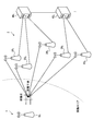
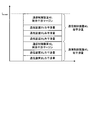
- FIG. 11 is an explanatory diagram illustrating an example of distribution of an interference margin to each communication device included in a secondary system. It is explanatory drawing which shows the hierarchical structure in CBRS. It is explanatory drawing which shows the band of CBRS.
- 1 is a diagram illustrating a configuration example of a communication system according to an embodiment of the present disclosure.
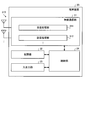
- 1 is a diagram illustrating a configuration example of a communication device according to an embodiment of the present disclosure.
- 1 is a diagram illustrating a configuration example of a terminal device according to an embodiment of the present disclosure.
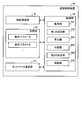
- 1 is a diagram illustrating a configuration example of a communication control device according to an embodiment of the present disclosure.
- FIG. 3 is an explanatory diagram illustrating an example of an interference model assumed in the present embodiment.
- FIG. 9 is an explanatory diagram illustrating another example of the interference model assumed in the present embodiment.
- FIG. 3 is an explanatory diagram for explaining a residual interference margin generated in a communication system.
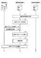
- FIG. 7 is a sequence diagram illustrating an example of a communication control process according to the embodiment of the present disclosure.
- FIG. 4 is an explanatory diagram for explaining a mutual interference group.
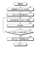
- 13 is a flowchart illustrating an example of an adjustment process according to an embodiment of the present disclosure.
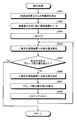
- 13 is a flowchart illustrating an example of a distribution process according to an embodiment of the present disclosure.
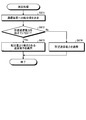
- 13 is a flowchart illustrating an example of a determination process according to an embodiment of the present disclosure.
- 1 is a diagram illustrating a configuration example of a communication system according to an embodiment of the present disclosure.
- 1 is a diagram illustrating a configuration example of a communication system 2 according to an embodiment of the present disclosure.
- a plurality of components having substantially the same function and configuration may be distinguished from each other by the same reference numeral followed by a different numeral.
- the communication control device as necessary 40 1, and as 40 2 having substantially the same function and structure.
- the same reference numeral is assigned.
- the communication control apparatus 40 1 and there is no particular need to distinguish between the 40 2 is simply referred to as a communication control unit 40.
- radio resources are generated by utilizing the temporal and spatial free radio waves (White Space) of the existing radio system (for example, Dynamic Spectrum Sharing (DSA)).
- DSA Dynamic Spectrum Sharing
- the CBRS that utilizes frequency sharing technology is used.
- citizens Broadband Radio Service is accelerating legislation and standardization.
- cognitive radio technology contributes not only to dynamic frequency sharing but also to improvement of frequency utilization efficiency by radio systems.
- ETSI EN 303 387 and IEEE 2.19.1-2014 specify a coexistence technique between wireless systems using free radio waves.
- the communication control device controls communication of the secondary system so as not to cause fatal interference with the primary system.
- the communication control device is a device that manages communication and the like of the communication device.
- the communication control device is a device (system) for managing radio wave resources (for example, frequency) such as a GLDB (Geo-location Database) and a SAS (Spectrum Access System).
- the communication control device corresponds to a communication control device 40 described later (for example, the communication control devices 40 1 and 40 2 shown in FIG. 4).
- the communication control device 40 will be described later in detail.
- the primary system is, for example, a system (for example, an existing system) that preferentially uses radio waves in a predetermined frequency band over other systems such as a secondary system.
- the secondary system is, for example, a system for secondary use (for example, dynamic frequency sharing) of radio waves in the frequency band used by the primary system.
- Each of the primary system and the secondary system may be configured by a plurality of communication devices, or may be configured by one communication device.
- the communication control device sets one or more communication devices included in the secondary system so that the accumulation of interference (Interference Aggregation) on the primary system does not exceed an interference tolerance (interference margin) of the primary system.
- the interference allowance is allocated to a plurality of communication devices.
- the allowable interference amount may be an interference amount predetermined by an operator of the primary system, a public organization that manages radio waves, or the like.
- the term “interference margin” refers to an allowable interference amount.
- the accumulation of interference may be referred to as accumulated interference power.
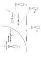
- FIG. 1 is an explanatory diagram showing an example of distribution of an interference margin to each communication device constituting a secondary system.
- the communication system 1 is a primary system
- the communication system 2 is a secondary system.
- Communication system 1 comprises a communication device 10 1 and the like.
- the communication system 2 comprises a communication device 20 1, 20 2, 20 3, and the like.
- the communication system 1 includes only one communication device 10, but the communication system 1 may include a plurality of communication devices 10.
- the communication system 2 includes three communication devices 20, but the communication device 20 may include fewer or more than three communication devices 20.
- the primary system and the secondary system are There may be more than one each.
- the communication device 10 1 and the communication devices 20 1 , 20 2 , 20 3 can each transmit and receive radio waves.
- the amount of interference the communication device 101 permits are I the accept.
- the amount of interference given to the predetermined protection point of the communication device 20 1, 20 2, 20 3 the communication system 1 (primary system) are the interfering amount I 1, I 2, I 3.
- the protection point is an interference calculation reference point for protecting the communication system 1.
- the communication control device controls the plurality of communication devices 20 so that the accumulation of interference to the predetermined protection point of the communication system 1 (the amount of received interference I 1 + I 2 + I 3 shown in FIG. 1) does not exceed the interference margin I accept.
- the interference margin I accept is allocated. For example, the communication control device distributes the interference margin I accept to each communication device 20 so that the amounts of interference I 1 , I 2 , and I 3 are each I accept / 3. Alternatively, the communication control device distributes the interference margin I accept to each communication device 20 such that the amounts of interference I 1 , I 2 , and I 3 are each smaller than I accept / 3.
- the method of allocating the interference margin is not limited to this example.
- the communication control device calculates the maximum transmission power (hereinafter, referred to as the maximum allowable transmission power) allowed for each communication device 20 based on the distributed interference amount (hereinafter, referred to as the distributed interference amount). For example, the communication control device calculates the maximum allowable transmission power of each communication device 20 by performing an inverse calculation from the distributed interference amount based on the propagation loss, the antenna gain, and the like. Then, the communication control device notifies each communication device 20 of information on the calculated maximum allowable transmission power.
- the distributed interference amount hereinafter, referred to as the distributed interference amount
- each communication device 20 is notified of the information of the maximum allowable transmission power from the communication control device, the communication device 20 does not always apply the notified maximum allowable transmission power. For example, for the following reasons (R1) to (R4), it is assumed that each communication device 20 does not apply the maximum allowable transmission power notified from the communication control device.
- R1 Due to hardware restrictions on the communication device 20, the communication device 20 can transmit radio waves only with a transmission power less than the maximum allowable transmission power.
- R2 Although the maximum allowable transmission power is applicable due to the hardware constraint of the communication device 20, the communication device 20 has passed the spectrum mask test (executed by a public organization) when the maximum allowable transmission power is applied. Absent.
- R3 For the purpose of network planning, the communication device 20 and the like operate communication with transmission power less than the maximum allowable transmission power.
- R4 Since the maximum allowable transmission power value desired by the communication device 20 has not been obtained, the radio wave transmission on the channel (for example, the frequency band used by the primary system) is abandoned.
- the communication device 20 3 is the desired maximum transmission power not be obtained, and abandoned wave transmission in the frequency band of the communication system 1 (channel).
- the interference margin I among the interference margin I the accept, intolerable without interference of at least interfering amount I 3 minutes is used.
- the surplus interference amount is referred to as a residual interference margin.
- the residual interference margin can be rephrased as a residual interference amount.
- the communication control device calculates the maximum allowable transmission power of each communication device 20 based on the distributed interference amount allocated to each communication device 20, and sends the calculated maximum allowable transmission power to each communication device 20. reported.
- the communication device 20 may notify the communication control device of a maximum transmission power desired by the communication device 20 (hereinafter, referred to as a desired maximum transmission power).
- the communication control device calculates an estimated value of interference that can occur when the desired maximum transmission power is applied to the communication device 20.
- the communication control device rejects the communication device 20 from transmitting radio waves at the desired maximum transmission power.
- the distributed interference amount distributed to the rejected communication device 20 can be a part or all of a residual interference margin (remaining interference amount).
- the communication device 20 can use the residual interference margin for wireless communication, it is possible to further effectively use radio wave resources.
- the communication control device distributes the residual interference margin to a part of the plurality of communication devices 20.
- the communication device 20 to which the interference amount has been allocated can transmit radio waves with higher output.
- the communication device 20 can communicate with a terminal device located far away or with more terminal devices at a time.
- the communication control device adjusts the operation parameter (for example, the maximum transmission power) of the communication device 20 within the range of the residual interference margin, thereby enabling more effective use of radio wave resources.
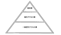
- FIG. 2 is an explanatory diagram showing a hierarchical structure in CBRS.
- the CBRS defines a hierarchical structure including an existing layer (Incumbent @ Tier), a priority access layer (Priority @ Access @ Tier), and a general authorized access layer (General @ Authorized @ Access @ Tier).
- the priority access layer (Priority Access Tier) is located above the general authorized access layer (General Authorized Access Tier)
- the existing layer (Incumbent Tier) is located above the priority access layer.
- a system located in the existing layer is the primary system
- a system located in the general authorized access layer and the priority access layer is the secondary system.
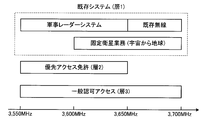
- FIG. 3 is an explanatory diagram showing a CBRS band.
- the primary system is a military radar system (Military Radar System), an existing radio system (Grand fathered Wireless System), or a fixed satellite service (Space to Earth) (Space-to-Earth). )).
- the military radar system is a shipborne radar.
- the secondary system is a wireless system called CBSD (Citizens Broadband Radio Service Device).
- CBSD CarD (Citizens Broadband Radio Service Device).
- the secondary system has further priority, and a priority access license (PAL: Priority Access License) that can license the shared band and a general authorized access (GAA: General Access Authorized Access) equivalent to no license are defined.
- PAL Priority Access License
- GAA General Access Authorized Access
- the primary system (communication system 1) of the present embodiment is not limited to the example shown in FIG.
- Another type of wireless system may be used as the primary system (communication system 1).
- the primary system may be a television broadcasting system such as a DVB-T (Digital Video Broadcasting-Terrestrial) system.
- the primary system may be a cellular communication system such as LTE (Long Term Evolution) and NR (New Radio).
- the primary system may be an aeronautical radio system such as ARNS (Aeronautical Radio Radio Navigation).
- the primary system is not limited to the above wireless system, but may be another type of wireless system.
- the free radio wave (White Space) used by the communication system 2 is not limited to the radio wave of Federal use band (3.55 to 3.70 GHz).
- the communication system 2 may use radio waves in a frequency band different from the Federal use band (3.55 to 3.70 GHz) as free radio waves.
- the primary system the communication system 1
- the communication system 2 may be a system that uses a TV white space as a free radio wave.
- the TV white space refers to a frequency band that is not used by the television broadcasting system among frequency channels allocated to the television broadcasting system (primary system). At this time, the TV white space may be a channel that is not used according to the area.
- the relationship between the communication system 1 and the communication system 2 is not limited to the frequency sharing relationship in which the communication system 1 is a primary system and the communication system 2 is a secondary system.
- the relationship between the communication system 1 and the communication system 2 may be a network coexistence relationship between the same or different wireless systems using the same frequency.
- the communication system 2 is a wireless communication system that performs wireless communication using a radio wave used by the communication system 1 (first wireless system) as a secondary communication.
- the communication system 2 is a wireless communication system that dynamically shares unused radio waves of the communication system 1.
- the communication system 2 provides a wireless service to a user or a device owned by the user by using a predetermined wireless access technology (Radio Access Technology).
- the communication system 2 may be a cellular communication system such as W-CDMA (Wideband Code Division Multiple Access), cdma2000 (Code Division Multiple Access 2000), LTE, and NR.
- LTE includes LTE-A (LTE-Advanced), LTE-A @ Pro (LTE-Advanced @ Pro), and EUTRA (Evolved Universal Terrestrial Radio Access).
- NR includes NRAT (New Radio Access Technology) and FEUTRA (Further EUTRA).
- the communication system 2 is not limited to a cellular communication system.
- the communication system 2 may be another wireless communication system such as a wireless LAN (Local Area Network) system, a television broadcasting system, an aeronautical wireless system, and a space wireless communication system.
- a wireless LAN Local Area Network
- the communication system 1 is a primary system, and the communication system 2 is a secondary system. As described above, each of the communication system 1 and the communication system 2 may be plural.
- the communication system 1 includes one communication device (the communication device 10 1 illustrated in FIG. 1 ).
- the communication system 1 may include a plurality of communication devices 10.
- the configuration of the communication device 10 may be the same as the configuration of the communication device 20 or the terminal device 30 described below.
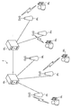
- FIG. 4 is a diagram illustrating a configuration example of the communication system 2 according to the embodiment of the present disclosure.
- the communication system 2 includes a communication device 20, a terminal device 30, and a communication control device 40.
- the communication system 2 provides a wireless service to a user or a device owned by the user by operating the wireless communication devices included in the communication system 2 in cooperation with each other.
- the wireless communication device is a device having a wireless communication function, and corresponds to the communication device 20 and the terminal device 30 in the example of FIG.
- the communication control device 40 may have a wireless communication function.
- the communication control device 40 can also be regarded as a wireless communication device.
- a wireless communication device may be simply referred to as a communication device.
- the communication system 2 may include a plurality of communication devices 20, terminal devices 30, and communication control devices 40, respectively.
- the communication system 1 includes a communication device 20 1, 20 2, 20 3, 20 4, 20 5 or the like as the communication device 20.
- the communication system 2 includes a terminal device 30 1, 30 2, 30 3, 30 4, etc. as a terminal device 30.
- the communication system 1 includes a communication control unit 40 1, 40 2, etc. as a communication control unit 40.
- a communication device may be referred to as a wireless system.
- the communication device 10 and communication device 20 1 to 20 5, respectively, is one of a wireless system.
- the terminal device 30 1 to 30 4, respectively, is one of a wireless system.
- the wireless system may be a single system including a plurality of wireless communication devices.
- a system including one or a plurality of communication devices 20 and one or a plurality of terminal devices 30 under the communication device 20 may be regarded as one wireless system.
- each of the communication system 1 and the communication system 2 can be regarded as one wireless system.
- a communication system including a plurality of wireless communication devices may be called a wireless communication system or simply a communication system.
- the communication device 20 (second wireless system) is a wireless communication device that performs wireless communication with the terminal device 30 or another communication device 20.
- the communication device 20 is a base station (also referred to as a base station device) of a wireless communication system.
- the wireless access technology used by the communication device 20 may be a cellular communication technology or a wireless LAN technology.
- the radio access technology used by the communication device 20 is not limited thereto, and may be another radio access technology.
- the size of the coverage of the communication device 20 may be as large as a macro cell or as small as a pico cell. Of course, the coverage of the communication device 20 may be extremely small, such as a femtocell. When the communication device 20 has a beam forming capability, a cell or a service area may be formed for each beam.
- the communication device 20 may be installed and operated by one company, or may be installed and operated by one person.
- the installation and operation entity of the communication device 20 is not limited to these.
- the communication device 20 may be installed and operated jointly by a plurality of businesses or a plurality of individuals.
- the communication device 20 may be a shared facility used by a plurality of businesses or a plurality of individuals. In this case, installation and operation of the equipment may be performed by a third party different from the user.
- the concept of a base station includes an access point and a wireless relay station (also referred to as a relay device). Further, the concept of a base station includes not only a structure having a function of the base station but also a device installed in the structure.
- the structure is, for example, a building (Building) such as an office building, a house, a steel tower, a station facility, an airport facility, a port facility, a stadium, and the like.
- the concept of a structure includes not only buildings, but also non-building structures such as tunnels, bridges, dams, walls, steel poles, and facilities such as cranes, gates, and windmills.
- the concept of a structure includes not only structures on the ground (on land) or underground, but also structures on water such as a pier and a megafloat, and structures underwater such as ocean observation facilities.
- the base station may be a base station (mobile station) configured to be movable.
- the base station (mobile station) may be a wireless communication device installed in the mobile object or the mobile object itself.
- the moving body may be a moving body that moves on the ground (land) (for example, a car, a bus, a truck, a train, a vehicle such as a linear motor car), or may move underground (for example, in a tunnel).
- Moving object for example, a subway
- the moving object may be a mobile terminal such as a smartphone.
- the moving object may be a moving object that moves on water (for example, a ship such as a passenger ship, a cargo ship, a hovercraft, etc.), or a moving object that moves in water (for example, a submarine, a submarine, an unmanned submarine, or the like). Submarine). Further, the moving object may be a moving object (for example, an airplane, an airship, an aircraft such as a drone) that moves in the atmosphere, or a space moving object (for example, an artificial satellite, a spacecraft, a universe) that moves outside the atmosphere. Station, or an artificial celestial body such as a spacecraft).
- a moving object for example, an airplane, an airship, an aircraft such as a drone
- a space moving object for example, an artificial satellite, a spacecraft, a universe
- the terminal device 30 is a communication device having a communication function.
- the terminal device 30 is, for example, a user terminal such as a mobile phone, a smart device (smartphone or tablet), a wearable terminal, a PDA (Personal Digital Assistant), and a personal computer.
- the terminal device 30 may be a device other than the user terminal, such as a machine in a factory or a sensor installed in a building.
- the terminal device 30 may be an M2M (Machine to Machine) device or an IoT (Internet of Things) device.
- the terminal device 30 may be a device having a relay communication function, as represented by D2D (Device @ to ⁇ Device).
- the terminal device 30 may be a device called CPE (Client ⁇ Premises ⁇ Equipment) used in a wireless backhaul or the like.
- the terminal device 30 may be a wireless communication device installed in a moving object, or may be the moving object itself.
- the communication control device 40 is a device that controls wireless communication of the communication device 20.
- the communication control device 40 is a device that determines an operation parameter used by the communication device 20 and instructs the communication device 20.
- the communication control device 40 may be a network manager that integrally controls wireless devices in the network.
- the communication control device 40 may be a control device such as Spectrum Manager / Coexistence Manager that performs radio wave interference control between wireless devices.
- a database database server, device, or system
- GLDB Global Location @ database
- SAS Spectrum @ Access @ System
- a plurality of communication control devices 40 may exist in one communication system 2.
- the communication control devices 40 exchange information of the communication devices 20 managed by each other, and perform necessary frequency assignment and interference control calculation.
- the control target of the communication control device 40 is the communication device 20, but the communication control device 40 may control the terminal device 30 under the control thereof.
- FIG. 5 is a diagram illustrating a configuration example of the communication device 20 according to the embodiment of the present disclosure.
- the communication device 20 is a wireless communication device (wireless system) that performs wireless communication with the terminal device 30 under the control of the communication control device 40.
- the communication device 20 is a base station device (ground station device) located on the ground.
- the communication device 20 may be a base station device arranged on a structure on the ground, or may be a base station device installed on a moving body moving on the ground.
- the communication device 20 may be an antenna installed in a structure such as a building and a signal processing device connected to the antenna.
- the communication device 20 may be a structure or a moving object itself. "Ground" is not only ground (land) but also ground, water, and underwater.
- the communication device 20 is not limited to a ground station device.
- the communication device 20 may be a base station device (non-ground station device) that moves or floats in the air or space.
- the communication device 20 may be an aircraft station device or a satellite station device.
- the aircraft station device may be a device mounted on an aircraft or the like, or may be the aircraft itself.
- the concept of an aircraft includes not only heavy aircraft such as airplanes and gliders, but also light aircraft such as balloons and airships. Further, the concept of an aircraft includes a rotary wing aircraft such as a helicopter and an autogyro.
- the aircraft station device (or the aircraft on which the aircraft station device is mounted) may be a manned aircraft or an unmanned aerial vehicle such as a drone.
- the satellite station device may be a device mounted on a space vehicle such as an artificial satellite or the space vehicle itself.
- the satellites serving as satellite station devices are a low orbit (LEO: Low Earth Orbiting) satellite, a medium orbit (MEO: Medium Earth Orbiting) satellite, a geostationary orbit (GEO: Geostationary Earth Orbiting) satellite, and a high elliptical orbit (HEO: Highly Elliptical Orbiting).
- LEO Low Earth Orbiting
- MEO Medium Earth Orbiting
- GEO Geostationary Earth Orbiting
- HEO Highly Elliptical Orbiting
- Any of satellites may be used.
- the satellite station device may be a device mounted on a low orbit satellite, a middle orbit satellite, a geostationary satellite, or a high elliptical orbit satellite.
- the communication device 20 may be a relay station device.
- the relay station device is, for example, an air station or an earth station.
- the relay station device can be considered as a type of the above-described relay device.
- the aviation station is a radio station installed on the ground or a moving body that moves on the ground in order to communicate with the aircraft station device.
- the earth station is a radio station located on the earth (including the air) to communicate with the satellite station device.
- the earth station may be a large earth station or a small earth station such as VSAT (Very Small Aperture Terminal).
- the earth station may be a VSAT control earth station (also called a master station or a HUB station) or a VSAT earth station (also called a slave station).
- the earth station may be a radio station installed in a mobile body that moves on the ground.
- an earth station mounted on a ship includes an earth station on board (ESV: Earth Stations on board Vessels).
- the earth station may include an aircraft earth station installed on an aircraft (including a helicopter) and communicating with a satellite station.
- the earth station may include an aeronautical earth station which is installed in a mobile body moving on the ground and communicates with an aircraft earth station via a satellite station.
- the relay station device may be a portable and mobile radio station that communicates with a satellite station or an aircraft station.
- the communication device 20 includes a wireless communication unit 21, a storage unit 22, a network communication unit 23, and a control unit 24. Note that the configuration shown in FIG. 5 is a functional configuration, and the hardware configuration may be different from this. Further, the functions of the communication device 20 may be distributed and implemented in a plurality of physically separated devices.
- the wireless communication unit 21 is a wireless communication interface that wirelessly communicates with another communication device (for example, the terminal device 30, the communication control device 40, and the other communication device 20).
- the wireless communication unit 21 operates under the control of the control unit 24.
- the wireless communication unit 21 may support a plurality of wireless access schemes.
- the wireless communication unit 21 may support both NR and LTE.
- the wireless communication unit 21 may support another cellular communication system such as W-CDMA and cdma2000.
- the wireless communication unit 21 may support a wireless LAN communication system in addition to the cellular communication system.
- the wireless communication unit 21 may support only one wireless access method.
- the wireless communication unit 21 includes a reception processing unit 211, a transmission processing unit 212, and an antenna 213.
- the wireless communication unit 21 may include a plurality of reception processing units 211, transmission processing units 212, and a plurality of antennas 213.
- each unit of the wireless communication unit 21 can be individually configured for each wireless access system. For example, if the communication device 20 supports NR and LTE, the reception processing unit 211 and the transmission processing unit 212 may be individually configured with NR and LTE.
- the reception processing unit 211 processes an uplink signal received via the antenna 213.
- the reception processing unit 211 includes a wireless reception unit 211a, a demultiplexing unit 211b, a demodulation unit 211c, and a decoding unit 211d.
- the radio reception unit 211a performs down-conversion, removal of unnecessary frequency components, control of amplification level, quadrature demodulation, conversion to digital signals, removal of guard intervals, and removal of frequency domain signals by fast Fourier transform from uplink signals. Perform extraction, etc.
- the wireless access method of the communication device 20 is a cellular communication method such as LTE.
- the demultiplexing unit 211b separates an uplink channel and an uplink reference signal such as a PUSCH (Physical Uplink Shared Channel) and a PUCCH (Physical Uplink Control Channel) from the signal output from the radio reception unit 211a.
- PUSCH Physical Uplink Shared Channel
- PUCCH Physical Uplink Control Channel
- the demodulation section 211c demodulates the received signal using a modulation scheme such as BPSK (Binary Phase Shift Keying) or QPSK (Quadrature Phase Shift keying) for the modulation symbol of the uplink channel.
- the modulation scheme used by the demodulation unit 211c may be 16 QAM (Quadrature Amplitude Modulation), 64 QAM, or 256 QAM.
- the decoding unit 211d performs a decoding process on the demodulated coded bits of the uplink channel.
- the decoded uplink data and uplink control information are output to the control unit 24.
- the transmission processing unit 212 performs transmission processing of downlink control information and downlink data.
- the transmission processing unit 212 includes an encoding unit 212a, a modulation unit 212b, a multiplexing unit 212c, and a wireless transmission unit 212d.
- the encoding unit 212a encodes the downlink control information and the downlink data input from the control unit 24 using an encoding method such as block encoding, convolutional encoding, and turbo encoding.
- the modulation section 212b modulates the coded bits output from the coding section 212a by a predetermined modulation method such as BPSK, QPSK, 16QAM, 64QAM, 256QAM.
- the multiplexing unit 212c multiplexes the modulation symbol of each channel and the downlink reference signal, and arranges the multiplexed symbol in a predetermined resource element.
- the wireless transmission unit 212d performs various signal processing on the signal from the multiplexing unit 212c.
- the wireless transmission unit 212d performs conversion to a time domain by fast Fourier transform, addition of a guard interval, generation of a baseband digital signal, conversion to an analog signal, quadrature modulation, up-conversion, removal of an extra frequency component, Processing such as power amplification is performed.
- the signal generated by transmission processing section 212 is transmitted from antenna 213.
- the storage unit 22 is a data readable / writable storage device such as a DRAM, an SRAM, a flash memory, and a hard disk.
- the storage unit 22 functions as a storage unit of the communication device 20.
- the storage unit 22 stores desired transmission power information, operation parameters, and the like.
- the desired transmission power information is transmission power information that the communication device 20 requests the communication control device 40 as transmission power information necessary for transmitting radio waves.
- the operation parameter is information (for example, setting information) on the radio wave transmission operation of the communication device 20.
- the communication operation parameter is information on the maximum value (maximum allowable transmission power) of the transmission power allowed for the communication device 20.
- the operation parameter is not limited to the information of the maximum allowable transmission power.
- the network communication unit 23 is a communication interface for communicating with another device.
- the network communication unit 23 is a LAN (Local Area Network) interface such as (Network Interface Card).
- the network communication unit 23 may be a USB (Universal Serial Bus) host controller, a USB interface including a USB port, and the like. Further, the network communication unit 23 may be a wired interface or a wireless interface.
- the network communication unit 23 functions as a network communication unit of the communication device 20.
- the network communication unit 23 communicates with another device under the control of the control unit 24.
- the control unit 24 is a controller that controls each unit of the communication device 20.
- the control unit 24 is realized by a processor such as a CPU (Central Processing Unit) and an MPU (Micro Processing Unit).
- the control unit 24 is realized by a processor executing various programs stored in a storage device inside the communication device 20 using a RAM (Random Access Memory) or the like as a work area.
- the control unit 24 may be realized by an integrated circuit such as an ASIC (Application Specific Integrated Circuit) or an FPGA (Field Programmable Gate Array).
- ASIC Application Specific Integrated Circuit
- FPGA Field Programmable Gate Array
- the control unit 24 includes an acquisition unit 241, a determination unit 242, a setting unit 243, and a transmission unit 244, as shown in FIG.
- Each block (the acquisition unit 241 to the transmission unit 244) constituting the control unit 24 is a functional block showing the function of the control unit 24.
- These functional blocks may be software blocks or hardware blocks.
- each of the functional blocks described above may be one software module realized by software (including a microprogram), or may be one circuit block on a semiconductor chip (die).
- each functional block may be one processor or one integrated circuit.
- the configuration method of the functional block is arbitrary.
- FIG. 6 is a diagram illustrating a configuration example of the terminal device 30 according to the embodiment of the present disclosure.
- the terminal device 30 is a communication device that performs wireless communication with the communication device 20 and the communication control device 40.
- the concept of a communication device includes not only a base station device but also a terminal device.
- the communication device can be called a wireless system.
- the terminal device 30 includes a wireless communication unit 31, a storage unit 32, an input / output unit 33, and a control unit. Note that the configuration shown in FIG. 6 is a functional configuration, and the hardware configuration may be different from this. Further, the functions of the terminal device 30 may be distributed and implemented in a plurality of physically separated configurations.
- the wireless communication unit 31 is a wireless communication interface that performs wireless communication with another communication device (for example, the communication device 20 and another terminal device 30).
- the wireless communication unit 31 operates under the control of the control unit 34.
- the wireless communication unit 31 supports one or a plurality of wireless access methods.
- the wireless communication unit 31 supports both NR and LTE.
- the wireless communication unit 31 may support another wireless access method such as W-CDMA or cdma2000.
- the wireless communication unit 31 includes a reception processing unit 311, a transmission processing unit 312, and an antenna 313.
- the wireless communication unit 31 may include a plurality of reception processing units 311, transmission processing units 312, and a plurality of antennas 313.
- each unit of the wireless communication unit 31 can be individually configured for each wireless access system.
- the reception processing unit 311 and the transmission processing unit 312 may be individually configured with LTE and NR.
- the configurations of the reception processing unit 311 and the transmission processing unit 312 are the same as those of the reception processing unit 211 and the transmission processing unit 212 of the communication device 20.
- the storage unit 32 is a data readable / writable storage device such as a DRAM, an SRAM, a flash memory, and a hard disk.
- the storage unit 32 functions as a storage unit of the terminal device 30.
- the input / output unit 33 is a user interface for exchanging information with a user.
- the input / output unit 33 is an operation device for a user to perform various operations, such as a keyboard, a mouse, operation keys, and a touch panel.
- the input / output unit 33 is a display device such as a liquid crystal display (Liquid Crystal Display) or an organic EL display (Organic Electroluminescence Display).
- the input / output unit 33 may be an audio device such as a speaker or a buzzer.
- the input / output unit 33 may be a lighting device such as an LED (Light Emitting Diode) lamp.
- the input / output unit 33 functions as input / output means (input means, output means, operation means, or notification means) of the terminal device 30.
- the control unit 34 is a controller that controls each unit of the terminal device 30.
- the control unit 34 is realized by, for example, a processor such as a CPU and an MPU.
- the control unit 34 is realized by a processor executing various programs stored in a storage device inside the terminal device 30 using a RAM or the like as a work area.
- the control unit 34 may be realized by an integrated circuit such as an ASIC or an FPGA.
- the CPU, MPU, ASIC, and FPGA can all be regarded as controllers.
- the communication control device 40 is a device that controls wireless communication of the communication device 20.
- the communication control device 40 may control wireless communication of the terminal device 30 via the communication device 20 or directly.
- the communication control device 40 is, for example, a network manager that integrally controls wireless devices in a network.
- the communication control device 40 is a Spectrum Manager / Coexistence Manager.
- the communication control device 40 may be a database server such as a GLDB (Geolocation database) or an SAS (Spectrum Access System).
- the communication control device 40 may be a device configuring a core network.
- the core network CN is, for example, EPC (Evolved @ Packet @ Core) or 5GC (5G @ Core @ network).
- EPC Evolved @ Packet @ Core
- 5GC 5G @ Core @ network
- the communication control device 40 may be, for example, a device having a function as a mobility management entity (MME).
- MME mobility management entity
- the communication control device 40 may be, for example, a device having a function as an AMF (Access / Mobility / Management / Function).
- the communication control device 40 does not necessarily need to be a device configuring a core network.
- the communication control device 40 may be a device having a function as an RNC (Radio Network Controller).
- RNC Radio Network Controller
- the communication control device 40 may have a gateway function.
- the communication control device 40 may be a device having a function as an S-GW (Serving Gateway) or a P-GW (Packet Data Network Gateway).
- the communication control device 40 may be a device having a function as a UPF (User @ Plane @ Function).
- the communication control device 40 does not necessarily have to be a device configuring the core network. For example, it is assumed that the core network is a W-CDMA or cdma2000 core network. At this time, the communication control device 40 may be a device that functions as an RNC (Radio Network Controller).
- RNC Radio Network Controller
- the communication control device 40 may be a system that controls a plurality of secondary systems.
- the communication system 2 can be regarded as a system including a plurality of secondary systems.
- FIG. 7 is a diagram illustrating a configuration example of the communication control device 40 according to the embodiment of the present disclosure.
- the communication control device 40 includes a wireless communication unit 41, a storage unit 42, a network communication unit 43, and a control unit 44. Note that the configuration shown in FIG. 7 is a functional configuration, and the hardware configuration may be different from this. Further, the functions of the communication control device 40 may be distributed and implemented in a plurality of physically separated configurations. For example, the communication control device 40 may be configured by a plurality of server devices.
- the wireless communication unit 41 is a wireless communication interface that wirelessly communicates with another communication device (for example, the communication device 20, the terminal device 30, and the other communication control device 40).
- the wireless communication unit 41 operates according to the control of the control unit 44.
- the wireless communication unit 31 supports one or a plurality of wireless access methods.
- the wireless communication unit 31 supports both NR and LTE.
- the wireless communication unit 31 may support another wireless access method such as W-CDMA or cdma2000.
- the configuration of the wireless communication unit 41 is the same as that of the wireless communication unit 21 of the communication device 20.
- the storage unit 42 is a data readable / writable storage device such as a DRAM, an SRAM, a flash memory, and a hard disk.
- the storage unit 22 functions as a storage unit of the communication device 20.
- the storage unit 22 stores the operation parameters of each of the plurality of communication devices 20 included in the communication system 2.
- the network communication unit 43 is a communication interface for communicating with another device.
- the network communication unit 43 may be a network interface or a device connection interface.
- the network communication unit 43 may be a LAN (Local Area Network) interface such as an NIC (Network Interface Card).
- the network communication unit 43 may be a USB (Universal Serial Bus) host controller, a USB interface including a USB port, and the like. Further, the network communication unit 43 may be a wired interface or a wireless interface.
- the network communication unit 43 functions as a communication unit of the communication control device 40.
- the network communication unit 43 communicates with the communication device 20 and the terminal device 30 under the control of the control unit 44.
- the control unit 44 is a controller that controls each unit of the communication control device 40.
- the control unit 44 is realized by, for example, a processor such as a CPU and an MPU.
- the control unit 44 is realized by a processor executing various programs stored in a storage device inside the communication control device 40 using a RAM or the like as a work area.
- the control unit 44 may be realized by an integrated circuit such as an ASIC or an FPGA.
- the CPU, MPU, ASIC, and FPGA can all be regarded as controllers.
- the control unit 44 includes an acquisition unit 441, a first determination unit 442, a calculation unit 443, a classification unit 444, a second determination unit 445, and a transmission unit 446.
- Each block (the acquisition unit 441 to the transmission unit 446) constituting the control unit 44 is a functional block showing the function of the control unit 44.
- These functional blocks may be software blocks or hardware blocks.
- each of the functional blocks described above may be one software module realized by software (including a microprogram), or may be one circuit block on a semiconductor chip (die).
- each functional block may be one processor or one integrated circuit.
- the configuration method of the functional block is arbitrary.
- the control unit 44 may be configured by a functional unit different from the above-described functional block. The operation of each block (the acquisition unit 441 to the transmission unit 446) constituting the control unit 44 will be described in detail in the description of the communication control processing and the like to be described later.
- Remaining interference margin As described with reference to FIG. 1, the communication system 2 (secondary system) has a residual interference margin (remaining interference amount) for various reasons (for example, the reasons of (R1) to (R4) described above). Can occur.
- the communication control device 40 distributes the residual interference margin to each of the communication devices 20, and adjusts the maximum allowable transmission power of the communication device 20 based on the distributed residual interference margin. Thereby, further effective use of radio wave resources is realized.
- the residual interference margin Before describing the processing related to the distribution of the residual interference margin according to the present embodiment, the residual interference margin will be described. First, an interference model assumed in the present embodiment will be described.
- FIG. 8 is an explanatory diagram illustrating an example of an interference model assumed in the present embodiment.
- the interference model shown in FIG. 8 is applied, for example, when the primary system has a service area.
- the communication system 1 primary system
- the communication system 1 is a wireless communication system having a service area.
- This service area is, for example, a protection area of the communication system 1.
- a plurality of interference calculation reference points (hereinafter, referred to as protection points) are set in the protection area.
- the protection point is set by, for example, an operator of the communication system 1 or a public organization that manages radio waves (hereinafter, referred to as an administrator).
- the administrator may divide the protection area into a grid shape and set the center of a predetermined grid as a protection point.
- the method of determining the protection point is arbitrary.
- the interference margin of each protection point is set by an administrator or the like.
- FIG. 8 illustrates interference that a plurality of communication devices 20 configuring the communication system 2 (secondary system) give to a protection point.
- the communication control device 40 of the communication system 2 controls the transmission power of the plurality of communication devices 20 so that the accumulated interference at each protection point does not exceed the set interference margin.
- FIG. 9 is an explanatory diagram illustrating another example of the interference model assumed in the present embodiment.
- the interference model shown in FIG. 9 is applied, for example, when the primary system performs only reception.
- the communication system 1 primary system
- the communication device 10 2 includes a receiving antenna as the communication device 10 2.
- Communication device 10 2 is, for example, a receiving antenna of the satellite ground stations.
- the communication control device 40 of the communication system 2 sets the position of the receiving antenna as a protection point, and controls the transmission power of the plurality of communication devices 20 so that the accumulated interference at that point does not exceed the interference margin.
- FIG. 10 is an explanatory diagram for explaining a residual interference margin generated in the communication system 2.
- FIG. 10 shows the total interference amount set for each of the two communication control devices 40 (communication control devices 40 1 and 40 2 ).
- FIG. 10 shows the interference amount (interference amount) given by a plurality of communication devices 20 (communication devices 20 1 to 20 5 ) under the control of two communication control devices 40 to a predetermined protection point of the communication system 1. It is shown.
- the amount of interference obtained by subtracting the amount of interference by the communication device 20 from the total amount of interference of each of the two communication control devices 40 is the residual interference margin.
- this amount of interference is set for each protection point and each frequency channel of the wireless communication system (primary system) to be protected.
- the communication control device 40 considers the amount of interference for the number of wireless communication systems having protection targets.
- the information of the interference margin may not be directly given to the communication control device 40.
- the communication control device 40 sets the interference margin based on information of a signal-to-interference-plus-noise-ratio (SINR) desired by the protection target (for example, the communication system 1). It may be calculated.
- the communication control device 40 may calculate an interference margin based on information of a carrier-to-interference-plus-noise-ratio (CINR).
- CINR carrier-to-interference-plus-noise-ratio
- the communication control device 40 may calculate the interference margin based on information of a signal-to-interference power ratio (SIR: Signal-to-Interference Ratio).
- SINR Required (dB) SINR Required (dB)
- SINR Required (dB) is expressed as the following equation (1).
- S is the signal power desired by the protection target
- N is the noise power received by the protection target.
- I accept is an allowable interference power.
- the interference margin also referred to as allowable interference power
- the communication control device 40 can calculate the interference margin I accept (dBm) by obtaining the signal-to-interference noise power ratio SINR, the desired signal power S, and the noise power N from the communication system 1 or the like.
- the method of calculating the interference margin is not limited to the above example.
- the communication control device 40 may calculate the interference margin using information other than the SINR, CINR, and SIR.
- the communication system 1 primary system
- the interference margin I accept at the protection point has been given to the communication control device 40 in advance by an administrator or the like.
- the communication control device 40 may obtain the interference margin I accept from another device (for example, a device configuring the communication system 1 or a device of a public organization that manages radio waves). Further, the communication margin control unit 40 may calculate the interference margin I accept based on information provided from the communication system 1 or the like.
- the communication system 1 may have a plurality of protection points and a plurality of frequency channels.
- the communication control device 40 controls the transmission power of the communication device 20 so as not to exceed the interference margin for all protection points and frequency channels.
- the communication control device 40 may need to consider interference to adjacent channels in addition to interference to the same channel. In this case, even if the following communication control processing is applied by focusing on one communication control device 40, one interference calculation reference point (protection point), a predetermined frequency channel of the primary system, and a frequency channel adjacent to the predetermined frequency channel. Good.
- the residual interference margin (the amount of residual interference) may occur in the secondary system for various reasons (for example, the reasons (R1) to (R4) described above). If this residual interference margin can be used for radio wave transmission, further effective use of radio wave resources becomes possible.
- the communication control device 40 realizes further effective use of radio wave resources by adjusting the once determined maximum allowable transmission power of the communication device 20 within the range of the residual interference margin.
- FIG. 11 is a sequence diagram illustrating an example of the communication control process according to the embodiment of the present disclosure. Although FIG. 11 shows only two communication control devices 40, the number of communication control devices 40 may be more than two. Of course, only one communication control device 40 may be provided. Each of the plurality of communication control devices 40 may perform the same processing. For example, each of the plurality of communication control devices 40 may determine the operation parameters of all of the plurality of communication devices 20 included in the communication system 2. In this case, the plurality of communication control devices 40 determine the same operation parameters for each predetermined communication device 20.
- the communication control device 40 1 is the subject of processing.
- another communication control device 40 (for example, the communication control device 40 2 ) may be the main subject of the processing.
- a plurality of communication control devices 40 may simultaneously perform the same processing (for example, the processing described below).
- the communication control device 40 may control wireless communication of the terminal device 30 via the communication device 20 or directly.
- the description of the communication device 20 described below can be replaced with the terminal device 30.
- the terminal device 30 is also a type of communication device.
- the communication control process described below is executed for each predetermined event (for example, for every fixed time or every time a control signal is received from a higher-level device).
- the acquisition unit 441 of the communication control device 40 1, the other communication control device 40, the exchange of information of the communication device 20 under management may include the following information (A) of the active communication device 20 and (B) the information of the inactive communication device 20.
- the information of the active communication device 20 may include the following information A1 to A6.
- the information on the inactive communication device 20 may include information on B1 to A4 below.
- the active communication device 20 is a communication device 20 for which the communication control device 40 has calculated the maximum allowable transmission power, or a communication device 20 which has already received radio wave transmission permission from the communication control device 40. Is shown. Other communication devices 20 registered only in the communication control device 40 are inactive communication devices 20.
- the information acquired by the acquisition unit 441 may be information on the hardware configuration of the communication device 20.
- information on the hardware configuration of the communication device 20 is referred to as hardware configuration information.
- the hardware configuration information may be information of “maximum transmission power applicable to the communication device 20” of A5 or B4.
- the information acquired by the acquisition unit 441 may be information on transmission power desired by the communication device 20 (for example, transmission power requested by the communication device 20 from the communication control device 40).
- the transmission power desired by the communication device 20 is called a desired transmission power.
- the acquisition unit 441 stores the acquired information in the storage unit 42.
- the first determination unit 442 determines the operation parameters (for example, such that the accumulated interference is equal to or less than the allowable interference power I accept ) of each of the plurality of communication devices 20 so as to satisfy the protection criterion of the primary system (for example,
- the first operation parameter is determined (step S2).
- the operation parameter is a setting used by the communication device 20 for radio wave transmission, and is, for example, information on the output of radio wave transmission.
- the operation parameter is information on the maximum transmission power (maximum allowable transmission power) allowed for the communication device 20.
- the transmission unit 446 of the communication control device 40 1 notifies the operating parameters (first operating parameter) to each of the plurality of communication devices 20 (step S3).
- Acquisition unit 241 of the communication device 20 acquires the operating parameters from the communication control device 40 1.
- the determination unit 242 of the communication device 20 determines whether the operation parameter is applicable to itself. For example, the determination unit 242 determines whether the maximum allowable transmission power included in the operation parameter is equal to or higher than the minimum power required for transmitting radio waves. Note that if the notified maximum allowable transmission power is higher than the power required by itself, the determination unit 242 determines the surplus power (the difference between the maximum allowable transmission power and the required power). Good.
- Acquisition unit 441 of the communication control device 40 1 obtains a judgment result from each of the plurality of communication devices 20.
- the acquisition unit 441 may acquire hardware configuration information and information on desired transmission power from each of the plurality of communication devices 20.
- the acquisition unit 441 stores the acquired information in the storage unit 42.
- calculation unit 443 of the communication control device 40 After obtaining the determination result, calculation unit 443 of the communication control device 40 1, based on the discrimination result acquired in operating parameters and S4 determined in step S2, and calculates the remainder interference margin (remainder interference amount) (step S5).
- the remainder interference margin is the amount of interference that can be allocated in addition to the communication control apparatus 40 1 of the communication device under the 20 (second wireless system).
- the second determining unit 445 of the communication control device 40 1 executes the adjustment process for adjusting the operating parameters of the communication device 20 (step S6). Specifically, second determining section 445 adjusts the maximum allowable transmission power determined in step S2 based on the residual interference margin calculated in step S5. The second determination unit 445 adjusts the maximum allowable transmission power of each communication device 20 within the range of the residual interference margin calculated in step S5, using the maximum allowable transmission power determined in step S2.
- Equation (3) shows the adjusted maximum allowable transmission power for the i-th communication device 20.
- i is the index of the communication device 20.
- i-th communication device 20 i indicates that the communication device 20 1 as long as a 1
- i indicates that the communication device 20 2 If the two.
- Equation (4) indicates that the cumulative interference of the plurality of communication devices 20 does not exceed the interference margin (interference margin) of the primary system p (for example, the communication system 1).
- the primary system p is a p-th primary system.
- the second determining unit 445 adjusts the maximum allowable transmission power of each communication device 20 so as to satisfy the condition shown in the following equation (4).
- f frequency.
- i Index of the communication device 20.
- P MaxTx, i (f) (dBm) the maximum allowable transmission power of the i-th communication device 20 before adjustment at the frequency f.
- ⁇ i (f) (dB) Adjustment amount (adjustment value) of the maximum allowable transmission power at the frequency f for the i-th communication device 20.
- P Tx, i Cx (f) (dBm) the maximum allowable transmission power of the i-th communication device 20 after the adjustment at the frequency f.
- I accept, p (f) (dBm) interference margin of primary system p at frequency f.
- N Tx (f) number of communication devices 20 at frequency f.
- L pi (dB) Propagation loss between the primary system p and the i-th communication device 20.
- G Ant (dB) Antenna gain of primary system p.
- the second determining unit 445 calculates the adjusted maximum allowable transmission power PTx, iCx (f) (dBm) based on the residual interference margin calculated in step S5.
- the residual interference margin is I Remained (f) (dBm)
- the residual interference margin I Remained (f) (dBm) is expressed by the following equation (5).
- the second determination unit 445 calculates the amount of change in the accumulated interference power resulting from the adjustment amount ⁇ i (f) (dB) shown in Expression (3) as the residual interference. Care is taken not to exceed the margin I Remained (f) (dB) . Therefore, the second determining unit 445 needs to consider the following equation (6) as a constraint.
- the summation ( ⁇ ) on the right side of Expression (6) indicates the difference between the amount of interference after transmission power adjustment and the amount of interference before transmission power adjustment in each communication device 20.
- the second determination unit 445 determines the adjusted maximum allowable transmission power P Tx, i Cx (f) (dBm) or the adjustment amount ⁇ for each of the communication devices 20 based on the constraint condition represented by Expression (6). Determine i (f) (dB) .
- the adjustment amount can be rephrased as an adjustment value.
- transmitting section 446 notifies communication apparatus 20 of the adjusted maximum allowable transmission power as an operation parameter (second operation parameter) (step S7). At this time, transmitting section 446 sets the combination of adjusted maximum allowable transmission power P Tx, i Cx (f) (dBm) and adjustment amount ⁇ i (f) (dB) as an operation parameter (second operation parameter). The second communication device 20 may be notified. Alternatively, transmitting section 446 operates both the maximum allowed transmission power P Tx, i Cx (f) (dBm) after adjustment and the maximum allowed transmission power P Tx, i (f) (dBm) before adjustment. It may be notified as a parameter (second operation parameter).
- These parameters notified by the transmitting unit 446 may be expressed in a true value notation or in a logarithmic notation.
- the notation format of the parameter may be another notation format.
- the parameter notation format can be arbitrarily changed as long as the parameter is finally transmitted to the communication device 20.
- Acquisition unit 441 of the communication device 20 acquires the operating parameters (second operating parameter) from the communication control device 40 1. Then, the setting unit 243 of the communication device 20 sets the operation parameters obtained by the obtaining unit 441. Then, the transmission unit 244 of the communication device 20 transmits a radio wave based on the set operation parameters. For example, the i-th communication device 20 outputs a radio wave so as not to exceed the adjusted maximum transmission power P Tx, i Cx (f) (dBm) .
- control unit 44 of the communication control device 40 1 ends the communication control processing.
- step S6 Determining the optimum ⁇ i (f) (dB) based on an arbitrary metric based on the above constraint requires a very large amount of calculation according to the number of communication devices 20. Therefore, in the present embodiment, the above-described adjustment processing in step S6 is performed in consideration of a mutual interference group.
- the mutual interference group is a group of the communication devices 20 that interfere with each other.
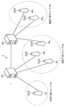
- FIG. 12 is an explanatory diagram for explaining a mutual interference group.
- the communication devices 20 1 to 20 3 form a mutual interference group # 1
- the communication devices 20 4 to 20 5 form a mutual interference group # 2
- the communication device 20 6 An interference group # 3 is formed. Note that, as in the mutual interference group # 3, one communication device 20 may belong to one mutual interference group.
- the communication devices 20 in the mutual interference group have a positional relationship in which the range (coverage) covering communication overlaps. Therefore, when a predetermined communication device 20 in the mutual interference group outputs a radio wave, it interferes with communication of another communication device 20 in the mutual interference group. For example, it located terminal device 30 to the overlapping position of the cell which cell the communication device 20 2 the communication device 20 1 is formed to form, and a communication device 20 1 and the terminal device 30 is communicating . In this case, when the communication device 20 2 has output a radio wave, the output may interfere the communication with the communication device 20 1 and the terminal device 30.
- FIG. 13 is a flowchart illustrating an example of the adjustment process according to the embodiment of the present disclosure.
- the grouping shown in step S61 may be performed by any of the communication device 20, the network manager that bundles the communication devices 20, or the communication control device 40.
- an entity other than the communication control device 40 performs grouping, it is desirable that the grouping information be notified from the entity to the communication control device 40.
- the communication control unit 40 1 performs the grouping.
- the classification unit 444 of the communication control device 40 1 performs the grouping of the communication device 20 (step S61).
- the communication devices 20 to be grouped are a group of communication devices that can provide cumulative interference power to one primary system.
- the classification unit 444 calculates, estimates, or derives a mutual interference relationship between the target communication devices 20, and treats the communication devices having the mutual interference relationship as one “mutual interference group”.
- the classification unit 444 may determine whether or not there is a mutual interference relationship (whether or not they interfere with each other) based on the superimposition relationship, for example, using the coverage of the communication device. Further, the classification unit 444 determines whether or not there is a mutual interference relationship based on the class information “Network Geometry Class” employed in IEEE Std 802.19.1-2014 and IEEE Std 802.19.1a-2017. May be determined.
- the classification unit 444 determines the superimposition relationship based on the coverage of the communication device 20, and performs grouping based on the determination result.
- the coverage itself can be determined by various metrics. For example, the classification unit 444 may determine, as the coverage of the communication device 20, the maximum area where the reception power level of the radio wave transmitted by the communication device 20 satisfies an arbitrary value. Alternatively, the classification unit 444 may determine, as the coverage of the communication device 20, a circular region whose center is the position of the communication device 20 and whose radius is an arbitrary distance. Of course, the classification unit 444 may determine the service area of the communication device 20 as the coverage of the communication device 20. The classification unit 444 can determine the coverage of the communication device 20 by various methods.
- the coverage of the communication device 20 may be calculated and determined by the communication control device 40 by itself, or the information notified from another device may be used as the coverage of the communication device 20 as it is.
- the communication control device 40 may acquire the coverage information calculated by the communication device 20 itself from the communication device 20 (or the network manager).
- the communication control device 40 may acquire the coverage information written in advance in the software of the communication device 20 from the communication device 20 (or the network manager).
- the information on the coverage of the communication device 20 is notified by the user of the communication device 20 (for example, a mobile communication carrier) to the communication control device 40 using an API provided by the communication control device 40 or a dedicated web form. You may.
- the classification unit 444 may perform grouping based on the class information of the communication device 20.
- the class information (transmission power class information) is information on a transmission power class defined for the communication device 20.
- the transmission power class can adopt various criteria. For example, C.C. F. In R Part 96 96 citizens Broadband Radio Service (CBRS), two types of classes, category A and category B, are defined as the transmission power class of a communication device corresponding to a base station / access point.
- Category A is a category having a maximum EIRP of 30 dBm / 10 MHz
- category B is a category having a maximum EIRP of 47 dBm / 10 MHz.
- the classification unit 444 may set the communication device 20 of the category B as one mutual interference group.
- the classification unit 444 may use the category B communication device 20 in which part or all of the coverage overlaps as one mutual interference group, in combination with the above-described coverage information.
- the transmission power class can adopt various criteria without depending on the example of CBRS.
- the classification unit 444 when a plurality of communication devices 20 form one cell, as represented by DAS (Distributed @ Antenna ⁇ System), the classification unit 444 generates a plurality of communication devices 20 that constitute one cell. It is also possible to determine as one “mutual interference group”.
- classification unit 444 does not necessarily need to classify the communication devices 20 into the mutual interference group.
- the classification unit 444 may classify the plurality of communication devices 20 into a plurality of groups based on another criterion.
- the “group” appearing in the following description is not necessarily a mutual interference group.
- “group” appearing in the following description can be replaced with “set”. For example, the “non-adjustable group” can be replaced with “unadjustable set”, and the “adjustment unnecessary group” can be replaced with “adjustment unnecessary set”.
- classification unit 444 does not necessarily need to classify the plurality of communication devices 20 included in the communication system 2 into a plurality of groups.
- the classification unit 444 may classify the plurality of communication devices 20 into one group.
- the second determining unit 445 of the communication control device 40 determines the m (f) (dBm) (step S62) .
- m is a group index. That is, distribution amount I Remained, m (f) (dBm), the distribution amount I Remained in the group m (predetermined set) shows the m (f) (dBm).
- the second determination unit 445 determines the distribution amount I Remained, m (f) (dB) so as to satisfy the constraints shown in the following Expressions (7) and (8).
- Equation (7) indicates that the amount of distribution I Remained, m (f) must not exceed the residual interference margin I Remained (f).
- Equation (7) indicates that the amount of interference allocated to one group (predetermined set) may be all or a part of the residual interference margin.
- Equation (8) also indicates that the sum of the allocation amounts allocated to each group must not exceed the residual interference margin I Remained (f) (dBm) .
- N Group shown in Expression (8) indicates the number of groups.
- the second determination unit 445 does not allocate the residual interference margin to the group (hereinafter, referred to as an unadjustable group). For example, when all the communication devices 20 belonging to the group cannot apply the residual interference margin to the transmission power due to hardware restrictions of the device, the second determination unit 445 does not allocate the residual interference margin to the group.
- the second determination unit 445 determines, from one or a plurality of groups classified in step S61, a non-adjustable group in which all the communication devices 20 to which the operation parameters cannot be adjusted. Then, the second determination unit 445 assigns the residual interference margin to another group (adjustable group) including at least one communication device 20 capable of adjusting the operation parameter without assigning the residual interference margin to the non-adjustable group. Assign some or all.
- the acquisition unit 441 may acquire the hardware configuration information of each communication device 20 from the storage unit 42. Then, the second determination unit 445 may determine, as a hardware configuration, a group in which the operation parameters cannot be adjusted by all the communication devices 20 to which the communication device 20 belongs as an unadjustable group.
- the second determination unit 445 does not allocate the residual interference margin to the group (hereinafter, referred to as an adjustment unnecessary group). For example, when the desired transmission power is applicable to all the communication devices 20 belonging to the group regardless of the restrictions imposed by the protection of the primary system, the second determining unit 445 does not allocate the residual interference margin to the group.
- the second determination unit 445 determines, from the one or a plurality of groups classified in step S61, an adjustment unnecessary group in which all the communication devices 20 to which the operation parameters do not need to be adjusted. Then, the second determination unit 445 assigns the residual interference margin to another group (adjustable group) including at least one communication device 20 capable of adjusting the operation parameter without assigning the residual interference margin to the adjustment unnecessary group. Assign some or all.
- the acquisition unit 441 may acquire information on the desired transmission power of each communication device 20 from the storage unit 42. Then, the second determination unit 445 may determine a group in which all the communication devices 20 to which the desired transmission power satisfies as the adjustment-free group.
- the second determination unit 445 allocates a residual interference margin based on the number of communication devices 20 included in each group. For example, the distribution amount I Remained, m (f) (dBm) to the group m can be calculated as in the following equation (9).
- N m, CommDevice is the number of communication devices 20 in group m.
- N Total and CommDevice are the total number of the communication devices 20.
- the number Nm of the communication devices 20 in the group m is a number excluding “the communication device 20 that cannot adjust the operation parameter” and / or “the communication device 20 that does not need to adjust the operation parameter”. May be. Further, the total number N Total, CommDevice of the communication devices 20 may be a number excluding “the communication device 20 whose operation parameters cannot be adjusted” and / or “the communication device 20 that does not require adjustment of the operation parameters”.
- the “communication device 20 whose operation parameters cannot be adjusted” is, for example, a communication device 20 that cannot apply a residual interference margin to transmission power due to hardware restrictions.
- the “communication device 20 that does not require adjustment of operation parameters” is, for example, the communication device 20 that already satisfies the desired transmission power.
- the second determination unit 445 selects a group that has not yet performed the distribution process from the plurality of groups (Step S63). Note that the second determination unit 445 may remove the non-adjustable group and / or the unnecessary adjustment group from the plurality of selection target groups before executing step S63. Then, the second determination unit 445 performs the distribution process on the selected group (predetermined set) (Step S64). The distribution processing is performed based on the residual interference margin distribution amount I Remained, m (f) (dBm) determined in step S62, based on the residual interference margin to each communication device 20 in the group (within a predetermined set). This is a process for determining the allocation amount.
- the distribution amount I Remained, m (f) (dBm) allocated to a predetermined group (predetermined set) is equally distributed to each communication device 20 in the predetermined group (predetermined set).
- the distribution amount to the communication device 20 is calculated as in the following Expression (10).
- I Remained, m, n (f) (dBm) is a distribution amount to the n-th communication device 20 in the group m.
- the second determination unit 445 determines whether the processing for all groups has been completed (step S65). If the processing has not been completed (Step S65: No), the second determination unit 445 returns the processing to Step S63. When the processing is completed (Step S65: Yes), the second determination unit 445 determines the adjustment amount of the operation parameter determined in Step S2 (Step S66).
- the operation parameter determined in step S2 is the maximum allowable transmission power P Tx, n (f) (dBm) .
- the second determination unit 445 determines the adjustment amount ⁇ n (f) (dB) of the maximum allowable transmission power as in the following equation (11).
- the meaning of each parameter is the same as the meaning shown in Expressions (3) and (4).
- N shown in Expression (11) means an index of the communication device 20 as in Expressions (3) and (4).
- control unit 44 of the communication control device 40 1 is returned to the communication control processing shown in FIG. 11.
- the adjustment processing described with reference to FIGS. 12 and 13 can be easily applied, for example, when the communication apparatuses 20 in the group adopt the same wireless access scheme and can use a common interference avoidance technique. It is. For example, it is assumed that the communication device 20 can use a technology such as LBT (Listen-Before-Talk). In this case, the communication device 20 performs an operation of not transmitting when detecting a radio wave of another communication device 20. Therefore, from the viewpoint of the communication control device 40, the transmission power of the communication device 20 can be increased without much concern about the interference in the group, and thus the above-described adjustment processing can be easily applied.
- LBT Listen-Before-Talk
- the communication control device 40 obtains information on the wireless access scheme included in the communication device 20 and sequentially allocates information so as to satisfy required characteristics based on the information.
- the required characteristic for example, transmission power can be assumed.
- the maximum allowable transmission power P MaxTx, i (f) (dBm) that is lower than the desired transmission power P desired, i (f) (dBm) of the i-th communication device 20 is set (for the sake of protection of the primary system ) ( Or decided).
- the communication control device 40 raises the maximum allowable transmission power to the initial desired transmission power or a magnitude close to the initial desired transmission power by using the distribution amount I Remained, m (f) (dBm) of the residual interference margin.
- the following algorithm can be implemented.
- FIG. 14 is a flowchart illustrating an example of the distribution process according to the embodiment of the present disclosure.
- an example of the distribution process will be described with reference to the flowchart of FIG.
- the distribution process described below is executed, for example, in step S64 of the adjustment process shown in FIG.
- the second determining unit 445 of the communication control device 40 1 calculates the deviation amount from the desired transmit power of the communication device 20 each in the group (step S641).
- the deviation amount of the i-th communication device 20 is ⁇ P i
- ⁇ P i P MaxTx, i (f) -P desired, i (f).
- P MaxTx, i (f) is the maximum allowable transmission power of the i-th communication device 20 before adjustment.
- P desired, i (f) is a desired transmission power of the i-th communication device 20.
- the second determination unit 445 sorts the communication devices 20 in an order of descending amounts (descending order) (step S642).
- the sorted index of the communication device 20 is referred to as i ′.
- the second determination unit 445 calculates the amount of distribution to the i′-th communication device 20 (Step S644).
- the distribution amount of the i′- th communication device 20 is I increase, i ′ (f) (dBm)
- I increase, i ′ (f) (dBm) ⁇ P i ′ (dBm) ⁇ L p ⁇ i ′ (dB) + G Ant (dB) .
- ⁇ P i ′ (dBm) is the deviation amount of the i′-th communication device 20, and is a term corresponding to the adjustment amount ⁇ i ′ (f) (dB) .
- L pi ′ (dB) is a propagation loss between the primary system and the i′th communication device 20.
- G Ant (dB) is the antenna gain of the primary system.
- the second determination unit 445 determines whether the total of the distributions exceeds the distribution amount to the group (Step S645). For example, the second determination unit 445 determines whether or not IRemained, m (f) (dBm) -Iincrease , i ' (f) (dBm) ⁇ 0 . In this step, I Remained, m (f) (dBm) means the remaining amount of the residual interference margin allocated to the group m.
- step S645: Yes If the total distribution exceeds the distribution amount to the group (step S645: Yes), the second determination unit 445 returns to the adjustment processing illustrated in FIG.
- the second determination unit 445 determines the distribution amount of the i′-th communication device 20 (Step S646).
- the second determination unit 445 may determine the allocation amount I update, i ′ (f) (dBm) calculated in step S644 as the allocation amount of the i′- th communication device 20 as it is.
- the second determination unit 445 determines a smaller amount than the distribution amount calculated in step S644 based on the information of the i′-th communication device 20 (for example, information on hardware configuration information or desired transmission power).
- the distribution amount of the second communication device 20 may be determined.
- transmission power was assumed as a required characteristic.
- other required characteristics for example, the Shannon capacity and the amount of interference between communication devices
- the allocation amounts may be sequentially determined in descending order of the required characteristics. For example, it is assumed that the required characteristics are substituted by the magnitude of the amount of interference between the communication devices 20.
- the second determination unit 445 performs communication in which the difference between the allowable interference amount of the communication device 20 and the cumulative interference (accumulated interference power) on the communication device 20 calculated based on the transmission power before adjustment is large. A surplus interference margin is allocated to another communication device 20 so that the amount of interference given to the device 20 increases. Then, the second determination unit 445 adjusts the transmission power value of each communication device 20 based on the distribution result.
- the second determination unit 445 may set the distribution amount of the residual interference margin determined based on the desired transmission power of the communication device 20 as the upper limit of the distribution amount. At this time, the second determination unit 445 may determine the transmission power of each communication device 20 as described below.
- FIG. 15 is a flowchart illustrating an example of the determination process according to the embodiment of the present disclosure.
- an example of the determination process will be described with reference to the flowchart of FIG.
- the determination process described below is executed, for example, in step S6 of the communication control process illustrated in FIG.
- the second determination unit 445 determines the amount of distribution to the communication device 20 based on any required characteristics (step S671). Then, the second determination unit 445 determines whether the transmission power (for example, the maximum allowable transmission power) derived from the distribution amount determined in step S671 does not exceed the desired transmission power of the communication device 20 (step S671). S672).
- the transmission power for example, the maximum allowable transmission power
- step S672 determines the distribution amount determined in step S671 as the distribution amount to be applied to the communication device 20. Then, the second determination unit 445 determines the transmission power derived from the distribution amount as an operation parameter applied to the communication device 20.
- step S672 determines the desired transmission power of the communication device 20 as an operation parameter of the communication device 20. Then, the second determination unit 445 applies the distribution amount based on the desired transmission power to the communication device 20.
- the second determining unit 445 ends the determining process.
- step S1 of the communication control process described above the communication control device 40 exchanges information of the communication device 20 under management with another communication control device 40. At this time, the communication control device 40 may exchange the following information (C1) to (C4) with another communication control device 40.
- This information can be exchanged when a plurality of communication control devices 40 exchange information required for calculation and perform distributed control of the communication device 20 (hereinafter, referred to as distributed control).
- the communication control device 40 may exchange information indicating the criteria for grouping with another communication control device 40.
- the communication control device 40 may exchange the group information itself indicating the result of the grouping with another communication control device 40.
- the communication control device 40 may transmit, for example, only information on the group including the communication device 20 managed by the other communication control device 40 to the other communication control device 40.
- FIG. 16 is a diagram illustrating a configuration example of the communication system 2 according to the embodiment of the present disclosure.
- the communication system 2 includes a communication control unit 40 3, the communication control unit 40 4.
- Communication control unit 40 3 manages the communication device 20 6, 20 7, 20 8.
- Communication control unit 40 4 manages the communication device 20 9, 20 10, 20 11.
- Communication device 20 6 is classified into interference group # 3
- the communication device 20 7-20 9 are classified into interference group # 4
- 4 communication control unit 40 3 and the communication control unit 40 exchanges only information about mutual interference group # 4. That is, the communication control unit 40 3 notifies only information on mutual interference group # 4 to the communication control unit 40 4. Communication control unit 40 3, information about mutual interference group # 3 is not necessary for the communication control device 40 4 does not notify the communication control unit 40 4. Similarly, the communication control unit 40 4 notifies only information on mutual interference group # 4 to the communication control device 40 3. Communication control unit 40 4, information about mutual interference Group # 5 is not necessary for the communication control device 40 3 does not notify the communication control unit 40 3. Thereby, the amount of information related to information exchange can be reduced.
- C2 Criteria for Determining Distribution of Surplus Interference Margin per Group This information can be exchanged when a plurality of communication control devices 40 perform distributed control.
- C4 Distribution amount of the residual interference margin and / or transmission power derived after the distribution
- This information is particularly useful when the plurality of communication control devices 40 are in a master-slave relationship (master, slave) or the like (hereinafter, central control). ). It is basically desirable that this information be notified from the master to the slave. The slave controls the subordinate communication device 20 based on this information.
- the plurality of communication control devices 40 determine the same operation parameter for each predetermined communication device 20. For example, in the example of FIG. 16, the communication control unit 40 4 and the communication control unit 40 3, at least, the mutual interference Group # 4 three communication devices belonging to 20 (the communication device 20 7-20 9), respectively the same operating parameters To determine. However, in some cases, a different determination result (adjusted transmission power) occurs between the communication control devices 40. In this case, for example, a reset request (redetermination request) may be transmitted from one of the communication control devices 40 to another communication control device 40 for the communication devices 20 having different calculation results.
- the transmitting unit 446 of the communication control device 40 3, the communication control unit 40 4, the second determining unit 445 of the communication control device 40 4 requests the operating parameters determined.
- the acquisition unit 441 of the communication control unit 40 3 obtains the operating parameters from the communication control unit 40 4.
- operating parameters the communication control unit 40 3 obtains, of the communication device 20 it manages, a in the operating parameters of the communication device 20 belonging to the group including a communication device 20 that is managed by the communication control unit 40 4 May be.
- the acquisition unit 441 of the communication control device 40 3, the operating parameters of Interference Group # 4 three communication devices belonging to 20 (the communication device 20 7-20 9) from the communication control unit 40 4 May be acquired.
- the second determining unit 445 of the communication control device 40 3 compares the operating parameters with the acquired operating parameters that it has determined from the communication control unit 40 4. For example, the communication control unit 40 3, the operating parameters of the communication device 20 7-20 9 determines whether the communication control apparatus 40 3 is different from the operating parameters determined.
- the transmission unit 446 of the communication control device 40 3, the communication control unit 40 4 transmits a reset request.
- the second determining unit 445 of the communication control device 40 4 the communication device 20 (e.g., the communication device 20 7-20 9) to reconfigure the operating parameters of (redetermination).
- the acquisition unit 441 of the communication control device 40 4, of the operating parameters the second determining unit 445 of the communication control device 40 3 is determined, the communication control device the operating parameters of the communication device 20 operating parameters are different 40 3 may be obtained.
- the second determining unit 445 of the communication control device 40 3 may determine the acquired operating parameters directly as operating parameters of the communication device 20.
- the communication control device 40 may correct the calculation of the communication control process using parameters such as an ACIR (Adjacent Channel Interference Ratio), an ACLR (Adjacent Channel Leakage Ratio), and an ACS (Adjacent Channel Selectivity). Further, the communication control device 40 may use characteristics such as blocking of the filter of the primary system.
- the number of primary systems (communication systems 1) to be protected is set to one.
- the communication control device 40 sets the operation parameters (adjustment of the operation parameters before adjustment) for each of the plurality of primary systems for one communication device 20 based on the method described in the communication control process described above. Including the amount). That is, the control unit 44 (the first determination unit 442 to the second determination unit 445) of the communication control device 40 determines, for one communication device 20, a plurality of operation parameters corresponding to a plurality of primary systems.
- the second determination unit 445 determines an operation parameter (for example, the smallest transmission power) at which the output of the communication device 20 is the smallest among the plurality of operation parameters as an operation parameter to be applied to the communication device 20.
- the operation parameter may be an operation parameter after adjustment or an adjustment amount of the operation parameter before adjustment.
- the communication control device 40 may allocate the distribution amount of the residual interference margin associated with the unselected operation parameter to the other communication devices 20 as the residual interference margin as it is. Then, the second determination unit 445 may determine an operation parameter of another communication device 20 based on the allocated distribution amount. At this time, the operation parameter may be an operation parameter after adjustment or an adjustment amount of the operation parameter before adjustment. Further effective use of radio resources can be realized.
- FIG. 17 is a diagram illustrating a configuration example of the communication system 2 according to the embodiment of the present disclosure.
- the communication system 2 includes a communication device 20 12, a communication device 20 13, and a communication device 20 14, a communication device 20 13.
- Communication devices 20 12-20 13 are classified into interference group # 6, the communication device 20 13-20 15 are classified into interference group # 7.
- the communication device 20 13 belongs to two groups of mutual interference group # 6 and mutual interference group # 7.
- the second determining unit 445 determines the distribution amount of the residual interference margin for each of the plurality of groups for the communication devices 20 belonging to the plurality of groups (hereinafter, referred to as the plurality of communication devices). For example, in the example of FIG. 17, the second determining unit 445 determines the allocation of the communication device 20 13. At this time, the second determination unit 445, the mutual interference group # 6, by executing the allocation process shown in FIG. 14, determines the distribution of the communication device 20 13. At the same time, the second determination unit 445, the mutual interference group # 7, by performing the allocation process shown in FIG. 14, determines the distribution of the communication device 20 13.
- the second determination unit 445 selects the smallest distribution amount among the plurality of distribution amounts as the distribution amount to the plurality of belonging communication devices. For example, in the example of FIG. 17, the second determination unit 445, allocation of the communication device 20 13 based on remainder interference margin assigned to the mutual interference Group # 6 (hereinafter referred to as a first distribution amount. a) allocation of the communication device 20 13 based on remainder interference margin assigned to the mutual interference group # 7 (hereinafter, the communication device with the called.) the second distribution amount, the allocation amount of smaller of 20 13 is selected as the distribution amount. Then, the second determination unit 445 determines the operation parameters of the plurality of belonging communication devices based on the selected distribution amount. At this time, the operation parameter may be an operation parameter after adjustment or an adjustment amount of the operation parameter before adjustment. Accordingly, in any group, the cumulative interference between the communication devices 20 in the group becomes smaller than the allowable interference amount.
- the unselected distribution amount (unselected distribution amount) among the plurality of distribution amounts may be directly allocated to another communication device 20 as a residual interference margin.
- the unselected distribution amount may be distributed to another communication device 20 in the target group (the group associated with the non-selected distribution amount).
- the second distribution amount as distribution amount to the communication device 20 13 is selected in the example of FIG. 17.
- the second determination unit 445 assigned to the other communication device 20 belonging to the first distribution amount to interference group # 6 (the communication device 20 12 and / or the communication device 20 14). Then, the second determination unit 445 may determine an operation parameter of another communication device 20 based on the allocated distribution amount.
- the operation parameter may be an operation parameter after adjustment or an adjustment amount of the operation parameter before adjustment. Further effective use of radio resources can be realized.
- the communication control device 40 of the present embodiment is not limited to the device described in the above embodiment.
- the communication control device 40 may be a device having a function other than controlling the communication device 20 that secondary uses a frequency band in which frequency sharing is performed.
- the function of the communication control device 40 of the present embodiment may be provided by a network manager.
- the network manager may be, for example, a C-BBU (Centralized Base Band Unit) having a network configuration called a C-RAN (Centralized Radio Access Network) or a device including the same.
- the function of the network manager may be provided in the base station (including the access point). These devices (such as a network manager) can also be regarded as communication control devices.
- the communication system 1 is a first wireless system
- the communication device 20 is a second wireless system.
- the first wireless system and the second wireless system are not limited to this example.
- the first wireless system may be a communication device (for example, the communication device 10)
- the second wireless system may be a communication system (communication system 2).
- the wireless system that appears in the present embodiment is not limited to a system including a plurality of devices, and can be appropriately replaced with “devices” and “terminals”.
- the communication control device 40 is a device belonging to the communication system 2, but is not necessarily a device belonging to the communication system 2.
- the communication control device 40 may be a device external to the communication system 2.
- the communication control device 40 may control the communication device 20 indirectly via a device included in the communication system 2 without directly controlling the communication device 20.
- a plurality of secondary systems (communication system 2) may exist.
- the communication control device 40 may manage a plurality of secondary systems. In this case, each secondary system can be regarded as a second wireless system.
- a macro cell in HetNET may be a primary system, and small cells and relay stations may be a secondary system.
- the base station may be a primary system, and Relay @ UE or Vehicle @ UE that realizes D2D or V2X (Vehicle-to-Everything) existing in the coverage may be a secondary system.
- the base station is not limited to a fixed type, and may be a portable / mobile type.
- the interface between each entity may be wired or wireless.
- the interface between each entity (communication control device, communication device, or terminal device) that appeared in the present embodiment may be a wireless interface that does not depend on frequency sharing.
- Examples of the wireless interface that does not depend on frequency sharing include a wireless interface provided by a mobile communication carrier via Licensed @ band and a wireless LAN communication using an existing unlicensed band.
- the control device that controls the communication device 10, the communication device 20, the terminal device 30, or the communication control device 40 of the present embodiment may be realized by a dedicated computer system, or may be realized by a general-purpose computer system. .
- a communication program for executing the above-described operation (for example, communication control processing, adjustment processing, distribution processing, or the like) is stored in a computer-readable recording medium such as an optical disk, a semiconductor memory, a magnetic tape, and a flexible disk. And distribute. Then, for example, the control device is configured by installing the program in a computer and executing the above-described processing.
- the control device may be a communication device 10, a communication device 20, a terminal device 30, or a device external to the communication control device 40 (for example, a personal computer). Further, the control device may be a device inside the communication device 10, the communication device 20, the terminal device 30, or the communication control device 40 (for example, the control unit 24, the control unit 34, or the control unit 44).
- the communication program may be stored in a disk device included in a server device on a network such as the Internet, and may be downloaded to a computer. Further, the above functions may be realized by cooperation of an OS (Operating System) and application software. In this case, a portion other than the OS may be stored in a medium and distributed, or a portion other than the OS may be stored in a server device and downloaded to a computer.
- OS Operating System
- each device shown in the drawings are functionally conceptual, and need not necessarily be physically configured as shown in the drawings.
- the specific form of distribution / integration of each device is not limited to the illustrated one, and all or a part thereof may be functionally or physically distributed / arbitrarily divided into arbitrary units according to various loads and usage conditions. Can be integrated and configured.
- the communication control device 40 determines the adjustment amount of the operation parameter of the communication devices 20 belonging to the predetermined set based on the information on the residual interference margin. . That is, the communication control device 40 distributes the residual interference margin to the communication device 20 to enable transmission of radio waves with higher output. Thereby, the communication device 20 can communicate with a terminal device located far away or with more terminal devices at a time. As a result, the communication control device 40 can realize effective use of radio wave resources.
- the communication control device 40 classifies the plurality of communication devices 20 into one or a plurality of groups (sets). Then, the communication control device 40 allocates a part or all of the residual interference margin to the predetermined set and, based on the information of the residual interference margin allocated to the predetermined set, operates the communication parameters of the communication devices 20 belonging to the predetermined set. The amount of adjustment is determined. Thus, the amount of calculation for determining the adjustment amount of the operation parameter can be reduced.
- a group (set) is a mutual interference group
- the communication control device 40 can allocate a residual interference margin to each group without considering radio interference between groups.
- the communication control device 40 only needs to consider the mutual interference between the communication devices 20 in the group when allocating the residual interference margin. Therefore, the communication control device 40 can determine the adjustment amount of the operation parameter very easily by setting the group (set) as the mutual interference group.
- ⁇ Communication control device 40 does not allocate the residual interference margin to the non-adjustable group (non-adjustable set) and / or the non-adjustable group (non-adjustable set). For this reason, the communication control device 40 does not waste the residual interference margin, so that more effective use of radio wave resources can be realized.
- the communication control device 40 allocates a large amount of interference to the communication device 20 in descending order of the difference between the maximum allowable transmission power and the desired transmission power. That is, the communication control device 40 allocates the interference amounts in descending order of the effect of the interference amount allocation. As a result, the distribution efficiency of the residual interference margin increases, so that the communication control device 40 can realize more effective use of radio wave resources.
- An acquisition unit that acquires information on a plurality of second wireless systems that perform wireless communication using radio waves in a frequency band used by the first wireless system;
- a first operation parameter determining operation parameter relating to radio wave transmission of each of the plurality of second radio systems based on information of the plurality of second radio systems so as to satisfy a protection criterion regarding radio wave interference of the first radio system;
- a decision unit A calculating unit that calculates a residual interference amount that can be additionally allocated to the second wireless system based on the operation parameter determined by the first determining unit and the protection criterion of the first wireless system;
- a classification unit that classifies the plurality of second wireless systems into one or a plurality of sets;
- a second determination unit that determines an adjustment amount of the operation parameter of the second wireless system belonging to a predetermined set of the one or more sets based on the information of the residual interference amount;
- a communication control device comprising: (2) The second determining unit allocates part or all of the residual interference amount to the predetermined set, and,
- the communication control device Determining an adjustment amount of the operation parameter of the second wireless system; The communication control device according to (1). (3) The classification unit classifies the plurality of second wireless systems into one or a plurality of sets based on whether or not they interfere with each other between the second wireless systems, The communication control device according to (2). (4) The acquisition unit acquires coverage information related to coverage of wireless communication of each of the plurality of second wireless systems, The classification unit classifies the plurality of second wireless systems into one or a plurality of sets based on the coverage information, The communication control device according to (2) or (3). (5) The classification unit specifies, based on the coverage information, a second wireless system on which the coverage overlaps from the plurality of second wireless systems, and classifies the specified second wireless system into the predetermined set.
- the acquisition unit acquires transmission power class information on a transmission power class of each of the plurality of second wireless systems
- the classification unit classifies the plurality of second wireless systems into one or a plurality of sets based on the transmission power class information,
- the communication control device according to (2) or (3) The classification unit specifies a second radio system of a predetermined transmission power class from the plurality of second radio systems based on the transmission power class information, and identifies the specified second radio system to the predetermined second radio system. Classify into sets, The communication control device according to (6).
- (8) Among the plurality of second wireless systems classifying a plurality of second wireless systems forming one cell into the predetermined set; The communication control device according to (2) or (3).
- the second determination unit determines, from the one or a plurality of sets, a non-adjustable set to which all of the second wireless systems to which the operation parameters cannot be adjusted are set. Assigning a part or all of the residual interference amount to another set including at least one of the second wireless systems capable of adjusting the operation parameter without assigning an amount;
- the communication control device according to any one of (2) to (8).
- the acquisition unit acquires information on a hardware configuration of each of the second wireless systems, The second determination unit determines, as a non-adjustable set, a set in which all the second wireless systems to which the operation parameters cannot be adjusted due to a hardware configuration.
- the communication control device according to (9).
- the second determination unit determines, from the one or a plurality of sets, an adjustment-free set in which all the second wireless systems to which the operation parameters do not need to be adjusted, and adds the residual interference to the adjustment-free set. Assigning a part or all of the residual interference amount to another set including at least one of the second wireless systems capable of adjusting the operation parameter without assigning an amount; The communication control device according to any one of (2) to (10). (12) The acquisition unit acquires information on desired transmission power of each of the second wireless systems, The second determination unit determines a set in which all the second wireless systems belong to the desired transmission power as an adjustment-free set, The communication control device according to (11).
- the first determination unit calculates a maximum allowable transmission power of each of the plurality of second wireless systems
- the second determining unit is configured to set the predetermined set based on a difference between a maximum allowable transmission power calculated by the first determining unit and a desired transmission power desired by the second wireless system. Determining the adjustment amount of the operation parameter of the second wireless system belonging to The communication control device according to any one of (2) to (12).
- the second determination unit allocates a larger interference amount to the second wireless systems belonging to the predetermined set in descending order of the divergence, and determines the adjustment amount of the operation parameter based on the allocated interference amount. , The communication control device according to (13).
- the second determining unit when a predetermined second wireless system, which is one of the plurality of second wireless systems, belongs to a plurality of sets, for each of the plurality of sets, the predetermined The distribution amount of the residual interference amount to the two wireless systems is determined, and the smallest distribution amount among the determined distribution amounts is selected as the distribution amount to the predetermined second wireless system, and based on the selected distribution amount. Determining the adjustment amount of the operation parameter of the predetermined second wireless system, The communication control device according to any one of (2) to (14). (16) The second determining unit allocates an unselected allocation amount among a plurality of allocation amounts to another second wireless system, and based on the allocated allocation amount, determines an operation parameter of the other second wireless system.
- the communication control device Determining the adjustment amount; The communication control device according to (15).
- the operation parameter determined by the determination unit of the first determination unit includes a maximum allowable transmission power that is a maximum transmission power allowed for the second wireless system, The second determination unit determines the adjustment amount of the maximum allowable transmission power determined by the first determination unit, The communication control device according to any one of (1) to (16).
- a transmission unit configured to transmit to the second wireless system a second operation parameter including at least one of the adjustment amount determined by the second determination unit and the operation parameter adjusted by the adjustment amount, The communication control device according to any one of (1) to (17).
- the first wireless system is a first communication system using radio waves in a predetermined frequency band
- the second wireless system is a communication device included in a second communication system using radio waves in the predetermined frequency band used by the first communication system.
- the communication control device according to any one of (1) to (18).
- the first communication system is a primary system that preferentially uses radio waves of the predetermined frequency band to the second communication system
- the second communication system is a secondary system that secondary uses radio waves in a frequency band used by the first communication system.
- the communication control device according to (19).
- (21) Acquiring information on a plurality of second wireless systems that perform wireless communication using radio waves in a frequency band used by the first wireless system; Based on the information on the plurality of second wireless systems, determine an operation parameter related to radio wave transmission of each of the plurality of second wireless systems so as to satisfy a protection criterion regarding radio wave interference of the first wireless system, Based on the determined operation parameters and the protection criterion of the first wireless system, calculate a residual interference amount that can be additionally allocated to the second wireless system, Classifying the plurality of second wireless systems into one or more sets, Based on the information on the residual interference amount, determine an adjustment amount of the operation parameter of the second wireless system belonging to a predetermined set of the one or more sets, Communication control method.
- a computer included in the communication control device An acquisition unit configured to acquire information on a plurality of second wireless systems that perform wireless communication using radio waves in a frequency band used by the first wireless system; A first operation parameter determining operation parameter relating to radio wave transmission of each of the plurality of second radio systems based on information of the plurality of second radio systems so as to satisfy a protection criterion regarding radio wave interference of the first radio system; Decision part, A calculating unit that calculates a residual interference amount that can be additionally allocated to the second wireless system based on the operation parameter determined by the first determining unit and the protection criterion of the first wireless system; A classification unit that classifies the plurality of second wireless systems into one or a plurality of sets; A second determining unit that determines an adjustment amount of the operation parameter of the second wireless system belonging to a predetermined set of the one or more sets based on the information on the residual interference amount; Communication control program to function as (23) A communication system comprising: a plurality of second wireless systems that perform wireless communication using radio waves in a frequency band used by
- the communication control device An acquisition unit configured to acquire information on the plurality of second wireless systems; A first operation parameter determining operation parameter relating to radio wave transmission of each of the plurality of second radio systems based on information of the plurality of second radio systems so as to satisfy a protection criterion regarding radio wave interference of the first radio system; A decision unit, A calculating unit that calculates a residual interference amount that can be additionally allocated to the second wireless system based on the operation parameter determined by the first determining unit and the protection criterion of the first wireless system; A classification unit that classifies the plurality of second wireless systems into one or a plurality of sets; A second determining unit that determines an adjustment amount of the operation parameter of the second wireless system belonging to a predetermined set of the one or more sets based on the information on the residual interference amount, Communications system.
Landscapes
- Engineering & Computer Science (AREA)
- Computer Networks & Wireless Communication (AREA)
- Signal Processing (AREA)
- Mobile Radio Communication Systems (AREA)
Abstract
L'invention concerne un dispositif de commande de communication (40) qui comprend : une unité d'acquisition (441) pour acquérir des informations relatives à une pluralité de seconds systèmes sans fil effectuant une communication sans fil à l'aide d'une onde radio d'une bande de fréquence utilisée par un premier système sans fil; une première unité de détermination (442) pour déterminer, sur la base d'informations concernant la pluralité de seconds systèmes sans fil, un paramètre de fonctionnement concernant la transmission d'ondes radio de chacun de la pluralité de seconds systèmes sans fil de sorte qu'une norme de protection concernant l'interférence des ondes radio du premier système sans fil soit satisfaite; une unité de calcul (443) pour calculer, sur la base du paramètre de fonctionnement déterminé par la première unité de détermination (442) et la norme de protection du premier système sans fil, une quantité excessive d'interférences qui peut être aussi attribuée aux seconds systèmes sans fil; une unité de classification (444) pour classifier la pluralité de seconds systèmes sans fil en un ou plusieurs ensembles; et une seconde unité de détermination (445) pour déterminer, sur la base d'informations concernant la quantité d'interférence en excès, la quantité de réglage du paramètre de fonctionnement des seconds systèmes sans fil appartenant à un ensemble prescrit parmi un ou plusieurs ensembles.
Priority Applications (3)
| Application Number | Priority Date | Filing Date | Title |
|---|---|---|---|
| EP19831352.0A EP3820188B1 (fr) | 2018-07-06 | 2019-06-06 | Dispositif de commande de communication et procédé de commande de communication |
| US17/250,293 US11388611B2 (en) | 2018-07-06 | 2019-06-06 | Communication control apparatus and communication control method |
| JP2020528742A JP7268680B2 (ja) | 2018-07-06 | 2019-06-06 | 通信制御装置、及び通信制御方法 |
Applications Claiming Priority (2)
| Application Number | Priority Date | Filing Date | Title |
|---|---|---|---|
| JP2018-129431 | 2018-07-06 | ||
| JP2018129431 | 2018-07-06 |
Publications (1)
| Publication Number | Publication Date |
|---|---|
| WO2020008800A1 true WO2020008800A1 (fr) | 2020-01-09 |
Family
ID=69060646
Family Applications (1)
| Application Number | Title | Priority Date | Filing Date |
|---|---|---|---|
| PCT/JP2019/022600 Ceased WO2020008800A1 (fr) | 2018-07-06 | 2019-06-06 | Dispositif de commande de communication et procédé de commande de communication |
Country Status (4)
| Country | Link |
|---|---|
| US (1) | US11388611B2 (fr) |
| EP (1) | EP3820188B1 (fr) |
| JP (1) | JP7268680B2 (fr) |
| WO (1) | WO2020008800A1 (fr) |
Cited By (3)
| Publication number | Priority date | Publication date | Assignee | Title |
|---|---|---|---|---|
| KR20210136232A (ko) * | 2020-05-07 | 2021-11-17 | 주식회사 쏠리드 | 스펙트럼 공유 시스템과 연동하는 분산 안테나 시스템 및 그 운영 방법 |
| EP4161008A4 (fr) * | 2020-05-25 | 2023-11-08 | Sony Group Corporation | Dispositif, système et procédé de traitement d'informations |
| US20240172142A1 (en) * | 2021-03-22 | 2024-05-23 | Sony Group Corporation | Communication control apparatus, communication control method, and communication apparatus |
Families Citing this family (4)
| Publication number | Priority date | Publication date | Assignee | Title |
|---|---|---|---|---|
| CN112470528B (zh) * | 2018-08-09 | 2022-06-14 | 华为技术有限公司 | 上行发射功率确定方法、网络设备和存储介质 |
| US11451343B2 (en) * | 2018-11-13 | 2022-09-20 | Qualcomm Incorporated | Message re-transmission in a group of devices |
| US20240147382A1 (en) * | 2022-10-26 | 2024-05-02 | Dish Wireless L.L.C. | Radio unit output power management |
| US12348370B2 (en) * | 2023-08-31 | 2025-07-01 | Cypress Semiconductor Corporation | Systems, methods, and devices for secure management of wireless device associations |
Citations (6)
| Publication number | Priority date | Publication date | Assignee | Title |
|---|---|---|---|---|
| JP2012151815A (ja) * | 2010-10-29 | 2012-08-09 | Sony Corp | 通信制御装置、通信制御方法、通信装置、通信方法及び通信システム |
| WO2014006802A1 (fr) * | 2012-07-05 | 2014-01-09 | 日本電気株式会社 | Premier dispositif de contrôle de spectre, système de contrôle de spectre, procédé de contrôle de spectre, et support non transitoire lisible par un ordinateur |
| WO2015025605A1 (fr) * | 2013-08-21 | 2015-02-26 | ソニー株式会社 | Appareil de commande de la communication et appareil de communication sans fil |
| JP5768812B2 (ja) | 2010-06-18 | 2015-08-26 | 日本電気株式会社 | 無線制御装置、第二送信局送信電力決定方法およびプログラム |
| JP2016123110A (ja) * | 2012-01-24 | 2016-07-07 | ソニー株式会社 | 通信装置、方法及びプログラム |
| JP2018085766A (ja) * | 2013-05-08 | 2018-05-31 | ソニー株式会社 | 通信制御装置、通信制御方法及び情報処理装置 |
Family Cites Families (4)
| Publication number | Priority date | Publication date | Assignee | Title |
|---|---|---|---|---|
| US7917149B2 (en) * | 2006-08-18 | 2011-03-29 | Fujitsu Limited | System and method for reusing wireless resources in a wireless network |
| WO2008114578A1 (fr) | 2007-03-19 | 2008-09-25 | Nec Corporation | Procédé de surveillance de cellule radio, son dispositif, et son logiciel |
| CN103404210B (zh) | 2011-03-11 | 2017-03-29 | 瑞典爱立信有限公司 | 用于确定空白空间干扰余量的方法 |
| CN104144482B (zh) | 2013-05-08 | 2019-04-30 | 中兴通讯股份有限公司 | 一种干扰分配方法、系统、数据库和重配置管理节点 |
-
2019
- 2019-06-06 WO PCT/JP2019/022600 patent/WO2020008800A1/fr not_active Ceased
- 2019-06-06 JP JP2020528742A patent/JP7268680B2/ja active Active
- 2019-06-06 US US17/250,293 patent/US11388611B2/en active Active
- 2019-06-06 EP EP19831352.0A patent/EP3820188B1/fr active Active
Patent Citations (6)
| Publication number | Priority date | Publication date | Assignee | Title |
|---|---|---|---|---|
| JP5768812B2 (ja) | 2010-06-18 | 2015-08-26 | 日本電気株式会社 | 無線制御装置、第二送信局送信電力決定方法およびプログラム |
| JP2012151815A (ja) * | 2010-10-29 | 2012-08-09 | Sony Corp | 通信制御装置、通信制御方法、通信装置、通信方法及び通信システム |
| JP2016123110A (ja) * | 2012-01-24 | 2016-07-07 | ソニー株式会社 | 通信装置、方法及びプログラム |
| WO2014006802A1 (fr) * | 2012-07-05 | 2014-01-09 | 日本電気株式会社 | Premier dispositif de contrôle de spectre, système de contrôle de spectre, procédé de contrôle de spectre, et support non transitoire lisible par un ordinateur |
| JP2018085766A (ja) * | 2013-05-08 | 2018-05-31 | ソニー株式会社 | 通信制御装置、通信制御方法及び情報処理装置 |
| WO2015025605A1 (fr) * | 2013-08-21 | 2015-02-26 | ソニー株式会社 | Appareil de commande de la communication et appareil de communication sans fil |
Non-Patent Citations (1)
| Title |
|---|
| See also references of EP3820188A4 |
Cited By (5)
| Publication number | Priority date | Publication date | Assignee | Title |
|---|---|---|---|---|
| KR20210136232A (ko) * | 2020-05-07 | 2021-11-17 | 주식회사 쏠리드 | 스펙트럼 공유 시스템과 연동하는 분산 안테나 시스템 및 그 운영 방법 |
| KR102741282B1 (ko) * | 2020-05-07 | 2024-12-11 | 주식회사 쏠리드 | 스펙트럼 공유 시스템과 연동하는 분산 안테나 시스템 및 그 운영 방법 |
| EP4161008A4 (fr) * | 2020-05-25 | 2023-11-08 | Sony Group Corporation | Dispositif, système et procédé de traitement d'informations |
| US12355674B2 (en) | 2020-05-25 | 2025-07-08 | Sony Group Corporation | Information processing device, information processing system, and information processing method for data classification |
| US20240172142A1 (en) * | 2021-03-22 | 2024-05-23 | Sony Group Corporation | Communication control apparatus, communication control method, and communication apparatus |
Also Published As
| Publication number | Publication date |
|---|---|
| EP3820188A4 (fr) | 2021-08-18 |
| US11388611B2 (en) | 2022-07-12 |
| EP3820188B1 (fr) | 2024-03-13 |
| US20210274357A1 (en) | 2021-09-02 |
| JPWO2020008800A1 (ja) | 2021-07-08 |
| EP3820188A1 (fr) | 2021-05-12 |
| JP7268680B2 (ja) | 2023-05-08 |
Similar Documents
| Publication | Publication Date | Title |
|---|---|---|
| EP3879868B1 (fr) | Dispositif de commande de communication, dispositif de communication et procédé de commande de communication | |
| JP7268680B2 (ja) | 通信制御装置、及び通信制御方法 | |
| US12356205B2 (en) | Communication control device, method of controlling communication, and communication system | |
| US12395944B2 (en) | Communication control device and communication control method | |
| JP7435597B2 (ja) | 通信制御装置、および通信制御方法 | |
| US12143827B2 (en) | Communication control apparatus, communication apparatus, and proxy apparatus | |
| US12219363B2 (en) | Information processing apparatus, information processing method, and information processing terminal apparatus | |
| WO2021085132A1 (fr) | Dispositif de traitement d'informations, procédé de traitement d'informations et dispositif de communication | |
| WO2021100601A1 (fr) | Dispositif de traitement d'informations, procédé de traitement d'informations et dispositif de communication | |
| CN114868415B (zh) | 通信控制设备和通信控制方法 | |
| WO2020045131A1 (fr) | Dispositif de commande de communication et procédé de commande de communication | |
| JP7415927B2 (ja) | 通信制御装置、通信制御方法、及び通信装置 |
Legal Events
| Date | Code | Title | Description |
|---|---|---|---|
| 121 | Ep: the epo has been informed by wipo that ep was designated in this application |
Ref document number: 19831352 Country of ref document: EP Kind code of ref document: A1 |
|
| ENP | Entry into the national phase |
Ref document number: 2020528742 Country of ref document: JP Kind code of ref document: A |
|
| NENP | Non-entry into the national phase |
Ref country code: DE |