WO2020008833A1 - Dispositif d'usinage au laser et procédé d'usinage au laser - Google Patents
Dispositif d'usinage au laser et procédé d'usinage au laser Download PDFInfo
- Publication number
- WO2020008833A1 WO2020008833A1 PCT/JP2019/023490 JP2019023490W WO2020008833A1 WO 2020008833 A1 WO2020008833 A1 WO 2020008833A1 JP 2019023490 W JP2019023490 W JP 2019023490W WO 2020008833 A1 WO2020008833 A1 WO 2020008833A1
- Authority
- WO
- WIPO (PCT)
- Prior art keywords
- sheet metal
- laser beam
- cutting
- nozzle
- laser
- Prior art date
- Legal status (The legal status is an assumption and is not a legal conclusion. Google has not performed a legal analysis and makes no representation as to the accuracy of the status listed.)
- Ceased
Links
Images


Classifications
-
- B—PERFORMING OPERATIONS; TRANSPORTING
- B23—MACHINE TOOLS; METAL-WORKING NOT OTHERWISE PROVIDED FOR
- B23K—SOLDERING OR UNSOLDERING; WELDING; CLADDING OR PLATING BY SOLDERING OR WELDING; CUTTING BY APPLYING HEAT LOCALLY, e.g. FLAME CUTTING; WORKING BY LASER BEAM
- B23K26/00—Working by laser beam, e.g. welding, cutting or boring
- B23K26/08—Devices involving relative movement between laser beam and workpiece
- B23K26/082—Scanning systems, i.e. devices involving movement of the laser beam relative to the laser head
-
- B—PERFORMING OPERATIONS; TRANSPORTING
- B23—MACHINE TOOLS; METAL-WORKING NOT OTHERWISE PROVIDED FOR
- B23K—SOLDERING OR UNSOLDERING; WELDING; CLADDING OR PLATING BY SOLDERING OR WELDING; CUTTING BY APPLYING HEAT LOCALLY, e.g. FLAME CUTTING; WORKING BY LASER BEAM
- B23K26/00—Working by laser beam, e.g. welding, cutting or boring
- B23K26/36—Removing material
- B23K26/38—Removing material by boring or cutting
-
- B—PERFORMING OPERATIONS; TRANSPORTING
- B23—MACHINE TOOLS; METAL-WORKING NOT OTHERWISE PROVIDED FOR
- B23K—SOLDERING OR UNSOLDERING; WELDING; CLADDING OR PLATING BY SOLDERING OR WELDING; CUTTING BY APPLYING HEAT LOCALLY, e.g. FLAME CUTTING; WORKING BY LASER BEAM
- B23K26/00—Working by laser beam, e.g. welding, cutting or boring
- B23K26/08—Devices involving relative movement between laser beam and workpiece
- B23K26/0869—Devices involving movement of the laser head in at least one axial direction
- B23K26/0876—Devices involving movement of the laser head in at least one axial direction in at least two axial directions
-
- B—PERFORMING OPERATIONS; TRANSPORTING
- B23—MACHINE TOOLS; METAL-WORKING NOT OTHERWISE PROVIDED FOR
- B23K—SOLDERING OR UNSOLDERING; WELDING; CLADDING OR PLATING BY SOLDERING OR WELDING; CUTTING BY APPLYING HEAT LOCALLY, e.g. FLAME CUTTING; WORKING BY LASER BEAM
- B23K37/00—Auxiliary devices or processes, not specially adapted for a procedure covered by only one of the other main groups of this subclass
- B23K37/02—Carriages for supporting the welding or cutting element
- B23K37/0211—Carriages for supporting the welding or cutting element travelling on a guide member, e.g. rail, track
- B23K37/0235—Carriages for supporting the welding or cutting element travelling on a guide member, e.g. rail, track the guide member forming part of a portal
-
- B—PERFORMING OPERATIONS; TRANSPORTING
- B23—MACHINE TOOLS; METAL-WORKING NOT OTHERWISE PROVIDED FOR
- B23K—SOLDERING OR UNSOLDERING; WELDING; CLADDING OR PLATING BY SOLDERING OR WELDING; CUTTING BY APPLYING HEAT LOCALLY, e.g. FLAME CUTTING; WORKING BY LASER BEAM
- B23K37/00—Auxiliary devices or processes, not specially adapted for a procedure covered by only one of the other main groups of this subclass
- B23K37/04—Auxiliary devices or processes, not specially adapted for a procedure covered by only one of the other main groups of this subclass for holding or positioning work
- B23K37/0408—Auxiliary devices or processes, not specially adapted for a procedure covered by only one of the other main groups of this subclass for holding or positioning work for planar work
-
- B—PERFORMING OPERATIONS; TRANSPORTING
- B23—MACHINE TOOLS; METAL-WORKING NOT OTHERWISE PROVIDED FOR
- B23K—SOLDERING OR UNSOLDERING; WELDING; CLADDING OR PLATING BY SOLDERING OR WELDING; CUTTING BY APPLYING HEAT LOCALLY, e.g. FLAME CUTTING; WORKING BY LASER BEAM
- B23K2101/00—Articles made by soldering, welding or cutting
- B23K2101/18—Sheet panels
-
- B—PERFORMING OPERATIONS; TRANSPORTING
- B23—MACHINE TOOLS; METAL-WORKING NOT OTHERWISE PROVIDED FOR
- B23K—SOLDERING OR UNSOLDERING; WELDING; CLADDING OR PLATING BY SOLDERING OR WELDING; CUTTING BY APPLYING HEAT LOCALLY, e.g. FLAME CUTTING; WORKING BY LASER BEAM
- B23K26/00—Working by laser beam, e.g. welding, cutting or boring
- B23K26/14—Working by laser beam, e.g. welding, cutting or boring using a fluid stream, e.g. a jet of gas, in conjunction with the laser beam; Nozzles therefor
- B23K26/1462—Nozzles; Features related to nozzles
Definitions
- the present disclosure relates to a laser processing machine and a laser processing method for processing a sheet metal by a laser beam.
- a laser processing machine that cuts a sheet metal with a laser beam emitted from a laser oscillator to produce a product having a predetermined shape has become widespread.
- a laser oscillator for emitting a laser beam used in a laser beam machine a fiber laser oscillator or a direct diode laser oscillator (DDL oscillator) that is small and low in cost compared to a large and high cost CO 2 laser oscillator. Is widely used.
- DDL oscillator direct diode laser oscillator
- the wavelength of the laser beam emitted from the CO 2 laser oscillator is about 10 ⁇ m, whereas the wavelength of the laser beam emitted from the fiber laser oscillator or the DDL oscillator is about 1 ⁇ m. Therefore, the laser beam emitted from the fiber laser oscillator or the DDL oscillator has a small beam waist, and the kerf width of the groove formed around the product by the irradiation of the laser beam is small.
- the laser beam machine is equipped with an assist gas supply device, which cuts the sheet metal while blowing the assist gas onto the sheet metal to discharge the molten metal in the kerf.
- an assist gas supply device which cuts the sheet metal while blowing the assist gas onto the sheet metal to discharge the molten metal in the kerf.
- the flow rate of the assist gas must be increased. That is, as the nozzle diameter increases, the amount of consumption of the assist gas increases, and the cost increases.
- a processing head having a nozzle formed with an opening for emitting a laser beam for cutting a sheet metal attached to a tip thereof, and a surface of the sheet metal.
- a moving mechanism that relatively moves the processing head, and a beam that vibrates a laser beam in a direction parallel to a cutting progress direction of the sheet metal when the processing head is relatively moved by the moving mechanism to cut the sheet metal.
- a vibration mechanism wherein the beam vibration mechanism has a laser beam amplitude of Qx, and an area occupying 86% of the light energy on the central side of the total light energy in the cross-sectional area of the laser beam on the upper surface of the sheet metal.
- the nozzle The present invention provides a laser processing machine characterized by using a nozzle having an opening diameter between a minimum value obtained by 2 Va ⁇ Vasd and a maximum value obtained by 2.5 Va + Vasd.
- a laser beam for cutting a sheet metal is emitted from a nozzle having an opening attached to a tip of a processing head, and is irradiated on the sheet metal.
- Cutting the sheet metal by moving the processing head relative to the surface of the sheet metal, and vibrating a laser beam in a direction parallel to a cutting progress direction of the sheet metal when cutting the sheet metal;
- Qx is the amplitude when vibrating the laser beam
- rtop is the radius of the first circular region having an area occupying 86% of the light energy on the center side of the total light energy in the cross-sectional area of the laser beam on the upper surface of the sheet metal
- the radius of the second circular region having an area occupying 86% of the light energy on the center side of the total light energy in the cross-sectional area of the laser beam on the lower surface of the sheet metal is rbottom.
- the calculated value Va is represented by the following equation, and when the standard deviation of the calculated value Va when cutting a sheet metal having a plurality of sheet thicknesses is Vasd, the minimum value obtained by 2 Va ⁇ Vasd and 2.5 + Vasd are used as the nozzle.
- a laser processing method characterized by using a nozzle having an opening diameter between the maximum value obtained in step (1) and (2).
- the sheet metal can be cut while the consumption amount of the assist gas is reduced as compared with the related art.
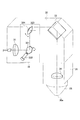
- FIG. 1 is a diagram illustrating an example of the overall configuration of a laser processing machine according to one or more embodiments.
- FIG. 2 is a perspective view illustrating a detailed configuration example of a collimator unit and a processing head in a laser processing machine according to one or more embodiments.
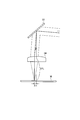
- FIG. 3 is a diagram for explaining the displacement of the irradiation position of the laser beam on the sheet metal by the beam vibration mechanism.
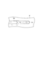
- FIG. 4 is a diagram showing a parallel vibration pattern of a laser beam.
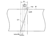
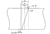
- FIG. 5 is a diagram for explaining how to determine an appropriate range of the amplitude when the laser beam is vibrated in the parallel vibration pattern.
- FIG. 6A is a diagram illustrating a state in which the amplitude of the laser beam is minimum.
- FIG. 6B is a diagram illustrating a state where the amplitude amount of the laser beam is maximum.
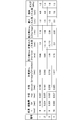
- FIG. 7 is a diagram showing, in a table format, an example used for determining the minimum nozzle diameter that can cut a sheet metal
- the consumption of the assist gas is reduced by using a nozzle having a smaller nozzle diameter than a conventional one as a nozzle used for cutting a sheet metal.
- a laser processing machine 100 includes a laser oscillator 10 that generates and emits a laser beam, a laser processing unit 20, and a process fiber 12 that transmits the laser beam emitted from the laser oscillator 10 to the laser processing unit 20.
- the laser beam machine 100 includes the operation unit 40, the NC device 50, the machining program database 60, the machining condition database 70, and the assist gas supply device 80.
- the NC device 50 is an example of a control device that controls each unit of the laser beam machine 100.
- the laser oscillator 10 a laser oscillator that amplifies the excitation light emitted from the laser diode and emits a laser beam of a predetermined wavelength or a laser oscillator that directly uses the laser beam emitted from the laser diode is preferable.
- the laser oscillator 10 is, for example, a solid-state laser oscillator, a fiber laser oscillator, a disk laser oscillator, or a direct diode laser oscillator (DDL oscillator).
- the laser oscillator 10 emits a 1 ⁇ m band laser beam having a wavelength of 900 nm to 1100 nm.
- the fiber laser oscillator emits a laser beam having a wavelength of 1060 nm to 1080 nm
- the DDL oscillator emits a laser beam having a wavelength of 910 nm to 950 nm.
- the laser processing unit 20 includes a processing table 21 on which a sheet metal W to be processed is placed, a gate-shaped X-axis carriage 22, a Y-axis carriage 23, a collimator unit 30 fixed to the Y-axis carriage 23, and a processing head 35.
- the sheet metal W is made of stainless steel. In one or more embodiments, the thickness of the sheet metal W is anywhere from 3 mm to 25 mm.
- the X-axis carriage 22 is configured to be movable on the processing table 21 in the X-axis direction.
- the Y-axis carriage 23 is configured to be movable on the X-axis carriage 22 in the Y-axis direction perpendicular to the X-axis.
- the X-axis carriage 22 and the Y-axis carriage 23 serve as a moving mechanism that moves the processing head 35 along the surface of the sheet metal W in the X-axis direction, the Y-axis direction, or any combined direction of the X-axis and the Y-axis. Function.
- the processing head 35 may have a fixed position and may be configured to move the sheet metal W.
- the laser processing machine 100 only needs to have a moving mechanism that moves the processing head 35 relative to the surface of the sheet metal W.
- a nozzle 36 having a circular opening 36a at the tip and emitting a laser beam from the opening 36a is attached.
- the sheet metal W is irradiated with the laser beam emitted from the opening 36 a of the nozzle 36.
- the assist gas supply device 80 supplies, for example, nitrogen to the processing head 35 as an assist gas.
- the assist gas is blown onto the sheet metal W from the opening 36a. The assist gas discharges the molten metal in the kerf where the sheet metal W has melted.
- the collimator unit 30 includes a collimation lens 31 that converts a divergent laser beam emitted from the process fiber 12 into parallel light (collimated light).
- the collimator unit 30 includes a galvano scanner unit 32 and a bend mirror 33 that reflects the laser beam emitted from the galvano scanner unit 32 downward in the Z-axis direction perpendicular to the X-axis and the Y-axis.
- the processing head 35 includes a focusing lens 34 that focuses the laser beam reflected by the bend mirror 33 and irradiates the sheet metal W with the laser beam.
- the laser beam machine 100 is centered so that the laser beam emitted from the opening 36a of the nozzle 36 is located at the center of the opening 36a. In the reference state, the laser beam is emitted from the center of the opening 36a.
- the galvano scanner unit 32 functions as a beam vibrating mechanism that vibrates the laser beam emitted from the opening 36a while traveling in the processing head 35 within the opening 36a. How the galvano scanner unit 32 vibrates the laser beam will be described later.
- the galvano scanner unit 32 includes a scan mirror 321 that reflects the laser beam emitted from the collimation lens 31, and a drive unit 322 that rotates the scan mirror 321 at a predetermined angle. Further, the galvano scanner unit 32 has a scan mirror 323 that reflects the laser beam emitted from the scan mirror 321 and a drive unit 324 that rotates the scan mirror 323 to a predetermined angle.
- the drive units 322 and 324 can reciprocally oscillate the scan mirrors 321 and 323 within a predetermined angle range based on the control by the NC device 50, respectively.
- the galvano scanner unit 32 vibrates the laser beam applied to the sheet metal W.
- the galvano scanner unit 32 is an example of a beam vibration mechanism, and the beam vibration mechanism is not limited to the galvano scanner unit 32 having a pair of scan mirrors.
- FIG. 3 shows a state in which one or both of the scan mirror 321 and the scan mirror 323 are tilted, and the position of the laser beam applied to the sheet metal W is displaced.
- a thin solid line bent by the bend mirror 33 and passing through the focusing lens 34 indicates the optical axis of the laser beam when the laser processing machine 100 is in the reference state.
- the angle of the optical axis of the laser beam incident on the bend mirror 33 is changed by the operation of the galvano scanner unit 32 located in front of the bend mirror 33, and the optical axis is shifted from the center of the bend mirror 33. Come off.
- the incident position of the laser beam on the bend mirror 33 before and after the operation of the galvano scanner unit 32 is set to the same position.
- the optical axis of the laser beam is displaced from the position shown by the thin solid line to the position shown by the thick solid line due to the action of the galvano scanner unit 32.
- the laser beam reflected by the bend mirror 33 is inclined at the angle ⁇
- the irradiation position of the laser beam on the sheet metal W is displaced by the distance ⁇ s.
- the focal length of the focusing lens 34 is EFL (Effective Focal Length)
- the distance ⁇ s is calculated by EFL ⁇ sin ⁇ .
- the galvano scanner unit 32 tilts the laser beam by the angle ⁇ in the direction opposite to the direction shown in FIG. 3, the irradiation position of the laser beam on the sheet metal W is displaced by the distance ⁇ s in the direction opposite to the direction shown in FIG. be able to.
- the distance ⁇ s is a distance smaller than the radius of the opening 36a, and is preferably a distance equal to or less than the maximum distance, which is a distance obtained by subtracting a predetermined margin from the radius of the opening 36a.
- the ⁇ NC device 50 can vibrate the laser beam in a predetermined direction in the plane of the sheet metal W by controlling the driving units 322 and 324 of the galvano scanner unit 32. By vibrating the laser beam, a beam spot formed on the surface of the sheet metal W can be vibrated.
- the NC device 50 reads the machining program from the machining program database 60 and selects any one of the plurality of machining conditions stored in the machining condition database 70.
- the NC device 50 controls the laser processing machine 100 to process the sheet metal W based on the read processing program and the selected processing condition.
- the laser beam machine 100 cuts the sheet metal W with a laser beam emitted from the laser oscillator 10 to produce a product having a predetermined shape.
- the galvano scanner unit 32 vibrates the laser beam as shown in FIG.
- the cutting direction of the sheet metal W is defined as the x direction
- the direction perpendicular to the x direction in the plane of the sheet metal W is defined as the y direction.
- FIG. 4 shows a vibration pattern without moving the processing head 35 in the x direction so that the vibration pattern can be easily understood.
- the galvano scanner unit 32 vibrates the beam spot Bs in the x direction within the groove Wk formed by the progress of the beam spot Bs based on the control of the NC device 50.
- This vibration pattern is called a parallel vibration pattern.
- the laser beam is vibrated in a parallel vibration pattern while the processing head 35 moves in the cutting direction.
- Non-Patent Document 1 describes cutting a sheet metal while vibrating a laser beam in a parallel vibration pattern.
- the parallel vibration pattern is a vibration pattern of Fx: Fy of 1: 0. .
- the kerf width K1 of the groove Wk is the same as the kerf width when the beam spot Bs is not vibrated in the parallel vibration pattern.
- the laser beam machine 100 cuts the sheet metal W while moving the processing head 35 in the cutting direction indicated by the white arrow and oscillating the laser beam applied to the sheet metal W in a parallel vibration pattern. .
- the laser beam does not need to be in a defocused state as in the related art, but may be in a just-focused state in which the focal point is located on the upper surface of the sheet metal W or in the vicinity thereof.
- the sheet metal W be supplied with intermittent energy that is sufficient and sufficient to satisfy the following two requirements.
- the first requirement is that the molten metal is melted within a single irradiation time of the oscillating laser beam, and the oscillating laser beam is irradiated to the molten metal a plurality of times within the time until the melted metal is discharged. (Especially viscosity) is maintained.
- the cut surface (the inner surface of the calf) does not melt excessively.
- the above two requirements are satisfied, and the low viscosity state of the molten metal is maintained for a longer time than before. Therefore, even if the kerf width K1 is the same as the conventional one, the molten metal in the kerf is easily discharged, and the quality of the cut surface is improved.
- the one that actually contributes to the melting of the metal is a circular region having an area occupying approximately 86% of the light energy at the center side of the total light energy in the cross-sectional area. It is.
- a circular region top86 having an area occupying 86% of the light energy on the center side of the cross-sectional area of the laser beam on the upper surface (that is, the area of the beam spot Bs) melts the sheet metal W.
- a circular region bottom 86 having an area occupying 86% of light energy on the center side of the cross-sectional area of the laser beam on the lower surface melts the sheet metal W.
- ⁇ L be the distance of the cutting front CF in the direction along the surface of the sheet metal W. Since the angle ⁇ of the cutting front CF is approximately 85 °, the angle ⁇ may be regarded as 85 °.
- the distance ⁇ L is obtained by dividing the sheet thickness t of the sheet metal W by tan ⁇ .
- FIG. 6A shows a state where the amplitude amount Qx is minimum.
- FIG. 5 corresponds to the state of FIG. 6A.
- the distance ⁇ L can be expressed by Expression (1) using the amplitude amount Qx, the radius rbottom of the circular region bottom86, and the radius rtop of the circular region top86.
- 6ctr in FIGS. 6A and 6B indicates the center of the nozzle 36.
- ⁇ L Qx + rbottom + rtop (1)
- FIG. 6B shows a state where the amplitude amount Qx is the maximum.
- the distance from the center of the circular area bottom86 to the lower end of the cutting front CF is equal to the radius rtop. Therefore, the distance ⁇ L in FIG. 6B is equal to the amplitude amount Qx.
- the NC device 50 causes the laser beam to vibrate by the galvano scanner unit 32 so as to satisfy Expression (2), the entire cutting front CF can be irradiated with the laser beam, and the sheet metal W can be cut well. Can be. Since the distance ⁇ L increases as the thickness t increases, the amplitude Qx needs to be increased as the thickness t increases.
- the angle ⁇ of the cutting front CF may be the Brewster angle at which the energy absorption rate of the metal is the highest, or may not be the Brewster angle.
- the Brewster angle is not essential as a requirement for melting the metal within one irradiation time of the oscillating laser beam.
- the relationship between the energy density and the time required for melting the metal may be established within one irradiation time.
- the molten metal may flow down from the relationship between the viscosity of the molten metal and the angle ⁇ of the cutting front CF.
- the laser beam machine and the laser beam machining method in order to cut a sheet metal made of stainless steel having a sheet thickness of 3 mm or more, the laser beam is appropriately vibrated in a parallel vibration pattern. It is preferable to set an appropriate amount of amplitude.
- the amplitude Qx when cutting the sheet metal W of 8 mm in thickness of 8 mm is 0.301 mm
- the radius rtop is 0.057 mm
- the radius rbottom is 0.255 mm.
- the amplitude Qx when cutting the sheet metal W having a sheet thickness of 10 mm of No. 4 is 0.500 mm
- the radius rtop is 0.057 mm
- the radius rbottom is 0.325 mm.
- the calculated value Va is defined by equation (3).
- the radius rbottom is multiplied by the route 2 for the following reason.
- the range where the gas flow of the assist gas flowing from the upper surface side to the lower surface side of the sheet metal W on the cutting front CF has an influence on the lower surface side is a distance longer than the radius rbottom. This is because the distance can be set within a range in which the influence is exerted.
- the standard deviation of the calculated value Va is Vasd
- the standard deviation Vasd is 0.279.
- the calculated minimum value Dmin of the nozzle diameter is represented by 2 Va ⁇ Vasd
- the calculated maximum value Dmax of the nozzle diameter is represented by 2.5 Va + Vasd.
- the minimum value Dmin and the maximum value Dmax when cutting the sheet metal W of numbers 1 to 4 are 0.44 and 1.18, 0.81 and 1.64, 1.16 and 2.08, 1.76, respectively. And 2.82.
- the magnification for the calculated value Va is set to 2 and 2.5 for the following reason.
- the inventor has noted that the calculated value Va approximately corresponds to the radius of the nozzle 36. Therefore, the minimum value of the magnification is 2 in order to make the diameter of the nozzle 36 (nozzle diameter).
- heat radiation heat transfer
- the actually existing nozzle diameters are 1.0 mm, 1.5 mm, 2.0 mm, 4.0 mm, 7.0 mm, and 10.0 mm, so that they can be used when cutting sheet metals W of numbers 1 to 4.
- the possible calculated nozzle diameters are 1.0 mm, 1.0 mm and 1.5 mm, 1.5 mm and 2.0 mm, and 2.0 mm, respectively. Therefore, the minimum nozzle diameters that can be used when cutting the sheet metals W of Nos. 1 to 4 are 1.0 mm, 1.0 mm, 1.5 mm, and 2.0 mm, respectively.
- the standard nozzle diameter used for cutting the sheet metal W of Nos. 1 to 3 is 4.0 mm
- the standard nozzle diameter used for cutting the sheet metal W of No. 4 is 7.0 mm. It is.
- the sheet metal W can be cut using the nozzle 36 having a smaller nozzle diameter than the standard nozzle diameter.
- the gas pressures of the assist gas when cutting the sheet metals W of Nos. 1 to 4 are 1.2 MPa, 1.4 MPa, 1.6 MPa, and 1.3 MPa, respectively.
- the laser beam machine and the laser beam machining method of one or more embodiments by vibrating the laser beam in a parallel vibration pattern, it is possible to cut the sheet metal W at a high speed with good cut surface quality. Further, according to the laser beam machine and the laser beam machining method of one or more embodiments, the nozzle 36 having a usable nozzle diameter in the range from the minimum value Dmin to the maximum value Dmax selected by the above theory is used. By using the method, the sheet metal W can be cut without impairing the effect that the quality of the cut surface is good and high-speed cutting is possible.
- the consumption amount of the assist gas can be significantly reduced as compared with the conventional case, so that the cost of manufacturing the product by cutting the sheet metal W is reduced. Can be done.
- the present invention is not limited to one or more embodiments described above, and can be variously changed without departing from the gist of the present invention.
Landscapes
- Physics & Mathematics (AREA)
- Optics & Photonics (AREA)
- Engineering & Computer Science (AREA)
- Mechanical Engineering (AREA)
- Plasma & Fusion (AREA)
- Laser Beam Processing (AREA)
Abstract
La présente invention concerne un mécanisme d'oscillation de faisceau amenant un faisceau laser à osciller dans une direction parallèle à la direction dans laquelle se déroule la découpe d'une feuille de métal (W). La quantité d'amplitude du faisceau laser est Qx, le rayon d'une première région circulaire ayant une zone occupant 86 % d'énergie optique sur le côté central de la totalité de l'énergie optique dans la zone de section transversale du faisceau laser sur une surface supérieure de la feuille de métal (W) est rtop, et le rayon d'une seconde région circulaire ayant une zone occupant 86 % d'énergie optique sur le côté central de la totalité de l'énergie optique dans la zone de section transversale du faisceau laser sur une surface inférieure de la feuille de métal (W) est rbottom. Une valeur calculée Va est exprimée par l'expression suivante. Lorsque l'écart type de la valeur calculée Va lors de la découpe de la feuille de métal (W) d'une pluralité d'épaisseurs est Vasd, en tant que buse (36) fixée à une tête de traitement (35), une buse dont le diamètre d'une ouverture (36a) est entre une valeur minimale obtenue par 2Va-Vasd et une valeur maximale obtenue par 2,5Va + Vasd est utilisée.
Priority Applications (2)
| Application Number | Priority Date | Filing Date | Title |
|---|---|---|---|
| US17/256,314 US11697176B2 (en) | 2018-07-06 | 2019-06-13 | Laser machining apparatus and laser machining method |
| EP19829853.1A EP3819069B1 (fr) | 2018-07-06 | 2019-06-13 | Procédé d'usinage au laser |
Applications Claiming Priority (2)
| Application Number | Priority Date | Filing Date | Title |
|---|---|---|---|
| JP2018128774A JP6592564B1 (ja) | 2018-07-06 | 2018-07-06 | レーザ加工機及びレーザ加工方法 |
| JP2018-128774 | 2018-07-06 |
Publications (1)
| Publication Number | Publication Date |
|---|---|
| WO2020008833A1 true WO2020008833A1 (fr) | 2020-01-09 |
Family
ID=68234898
Family Applications (1)
| Application Number | Title | Priority Date | Filing Date |
|---|---|---|---|
| PCT/JP2019/023490 Ceased WO2020008833A1 (fr) | 2018-07-06 | 2019-06-13 | Dispositif d'usinage au laser et procédé d'usinage au laser |
Country Status (4)
| Country | Link |
|---|---|
| US (1) | US11697176B2 (fr) |
| EP (1) | EP3819069B1 (fr) |
| JP (1) | JP6592564B1 (fr) |
| WO (1) | WO2020008833A1 (fr) |
Cited By (1)
| Publication number | Priority date | Publication date | Assignee | Title |
|---|---|---|---|---|
| DE102022118281A1 (de) | 2022-07-21 | 2024-02-01 | TRUMPF Werkzeugmaschinen SE + Co. KG | Laserschneidverfahren mit oszillierendem Laserstrahl und optimierter Schneidgaszufuhr |
Families Citing this family (1)
| Publication number | Priority date | Publication date | Assignee | Title |
|---|---|---|---|---|
| JP2023042497A (ja) * | 2021-11-17 | 2023-03-27 | 株式会社キーエンス | レーザ加工装置 |
Citations (4)
| Publication number | Priority date | Publication date | Assignee | Title |
|---|---|---|---|---|
| JP2005288541A (ja) * | 2004-03-31 | 2005-10-20 | Eo Technics Co Ltd | ポリゴンミラーを利用するレーザ加工装置 |
| JP2007021579A (ja) * | 2005-06-17 | 2007-02-01 | Nippon Steel Corp | 倣いレーザビーム振動装置及びビーム振動レーザ加工装置 |
| WO2015156119A1 (fr) * | 2014-04-10 | 2015-10-15 | 三菱電機株式会社 | Dispositif de traitement au laser et procédé de traitement au laser |
| JP2018128774A (ja) | 2017-02-07 | 2018-08-16 | 株式会社エスブランドマネジメント | 消耗品管理システム |
Family Cites Families (4)
| Publication number | Priority date | Publication date | Assignee | Title |
|---|---|---|---|---|
| JP3453972B2 (ja) * | 1995-12-27 | 2003-10-06 | トヨタ自動車株式会社 | レーザ溶接方法および装置 |
| DE102008053397B4 (de) * | 2008-05-20 | 2012-12-27 | Fraunhofer-Gesellschaft zur Förderung der angewandten Forschung e.V. | Verfahren zum Schmelzschneiden von Werkstücken mit Laserstrahlung |
| CN102653030B (zh) * | 2012-04-20 | 2015-05-20 | 华中科技大学 | 一种多功能激光加工头 |
| JP6170643B1 (ja) | 2016-04-14 | 2017-07-26 | 株式会社アマダホールディングス | レーザ加工機及びレーザ加工方法 |
-
2018
- 2018-07-06 JP JP2018128774A patent/JP6592564B1/ja active Active
-
2019
- 2019-06-13 US US17/256,314 patent/US11697176B2/en active Active
- 2019-06-13 WO PCT/JP2019/023490 patent/WO2020008833A1/fr not_active Ceased
- 2019-06-13 EP EP19829853.1A patent/EP3819069B1/fr active Active
Patent Citations (4)
| Publication number | Priority date | Publication date | Assignee | Title |
|---|---|---|---|---|
| JP2005288541A (ja) * | 2004-03-31 | 2005-10-20 | Eo Technics Co Ltd | ポリゴンミラーを利用するレーザ加工装置 |
| JP2007021579A (ja) * | 2005-06-17 | 2007-02-01 | Nippon Steel Corp | 倣いレーザビーム振動装置及びビーム振動レーザ加工装置 |
| WO2015156119A1 (fr) * | 2014-04-10 | 2015-10-15 | 三菱電機株式会社 | Dispositif de traitement au laser et procédé de traitement au laser |
| JP2018128774A (ja) | 2017-02-07 | 2018-08-16 | 株式会社エスブランドマネジメント | 消耗品管理システム |
Non-Patent Citations (2)
| Title |
|---|
| "Shaping the beam for the best cut", THE FABRICATOR, vol. 67, January 2017 (2017-01-01) |
| See also references of EP3819069A4 |
Cited By (1)
| Publication number | Priority date | Publication date | Assignee | Title |
|---|---|---|---|---|
| DE102022118281A1 (de) | 2022-07-21 | 2024-02-01 | TRUMPF Werkzeugmaschinen SE + Co. KG | Laserschneidverfahren mit oszillierendem Laserstrahl und optimierter Schneidgaszufuhr |
Also Published As
| Publication number | Publication date |
|---|---|
| EP3819069A1 (fr) | 2021-05-12 |
| EP3819069A4 (fr) | 2021-09-01 |
| EP3819069B1 (fr) | 2022-10-19 |
| US11697176B2 (en) | 2023-07-11 |
| JP6592564B1 (ja) | 2019-10-16 |
| US20210260703A1 (en) | 2021-08-26 |
| JP2020006397A (ja) | 2020-01-16 |
Similar Documents
| Publication | Publication Date | Title |
|---|---|---|
| JP6592563B1 (ja) | レーザ加工機及びレーザ加工方法 | |
| JP6638011B2 (ja) | レーザ加工機及びレーザ加工方法 | |
| JP5207371B2 (ja) | レーザ加工装置 | |
| JP2009226473A (ja) | ファイバレーザ加工機における集光直径の変換制御方法及びその装置 | |
| JP6116757B2 (ja) | レーザ加工装置 | |
| JP2009178768A (ja) | レーザ溶接方法およびレーザ溶接装置 | |
| JP2009178720A (ja) | レーザ加工装置 | |
| WO2022202797A1 (fr) | Dispositif d'usinage au laser et procédé d'usinage au laser | |
| JP6592564B1 (ja) | レーザ加工機及びレーザ加工方法 | |
| JP2006150433A (ja) | レーザ加工装置 | |
| JP6643442B1 (ja) | レーザ加工機及びレーザ加工方法 | |
| JP2013056372A (ja) | レーザ加工装置 | |
| EP3831527B1 (fr) | Dispositif d'usinage au laser et procédé d'usinage au laser | |
| JP2012236228A (ja) | レーザ溶接方法およびレーザ溶接装置 | |
| WO2023085160A1 (fr) | Procédé de traitement au laser et dispositif de traitement au laser | |
| WO2023085156A1 (fr) | Procédé de traitement laser et machine de traitement laser | |
| JP6538910B1 (ja) | レーザ加工機及びレーザ加工方法 | |
| JP6820358B2 (ja) | レーザ加工機及びレーザ加工方法 | |
| CN117396298A (zh) | 激光加工机以及激光加工方法 | |
| JP2012210659A (ja) | レーザ溶接方法およびレーザ溶接装置 |
Legal Events
| Date | Code | Title | Description |
|---|---|---|---|
| 121 | Ep: the epo has been informed by wipo that ep was designated in this application |
Ref document number: 19829853 Country of ref document: EP Kind code of ref document: A1 |
|
| NENP | Non-entry into the national phase |
Ref country code: DE |