WO2020008834A1 - Dispositif de traitement d'image, procédé et système endoscopique - Google Patents
Dispositif de traitement d'image, procédé et système endoscopique Download PDFInfo
- Publication number
- WO2020008834A1 WO2020008834A1 PCT/JP2019/023492 JP2019023492W WO2020008834A1 WO 2020008834 A1 WO2020008834 A1 WO 2020008834A1 JP 2019023492 W JP2019023492 W JP 2019023492W WO 2020008834 A1 WO2020008834 A1 WO 2020008834A1
- Authority
- WO
- WIPO (PCT)
- Prior art keywords
- image
- images
- light
- endoscope
- observation
- Prior art date
- Legal status (The legal status is an assumption and is not a legal conclusion. Google has not performed a legal analysis and makes no representation as to the accuracy of the status listed.)
- Ceased
Links
Images




Classifications
-
- A—HUMAN NECESSITIES
- A61—MEDICAL OR VETERINARY SCIENCE; HYGIENE
- A61B—DIAGNOSIS; SURGERY; IDENTIFICATION
- A61B1/00—Instruments for performing medical examinations of the interior of cavities or tubes of the body by visual or photographical inspection, e.g. endoscopes; Illuminating arrangements therefor
-
- A—HUMAN NECESSITIES
- A61—MEDICAL OR VETERINARY SCIENCE; HYGIENE
- A61B—DIAGNOSIS; SURGERY; IDENTIFICATION
- A61B1/00—Instruments for performing medical examinations of the interior of cavities or tubes of the body by visual or photographical inspection, e.g. endoscopes; Illuminating arrangements therefor
- A61B1/04—Instruments for performing medical examinations of the interior of cavities or tubes of the body by visual or photographical inspection, e.g. endoscopes; Illuminating arrangements therefor combined with photographic or television appliances
- A61B1/045—Control thereof
-
- G—PHYSICS
- G02—OPTICS
- G02B—OPTICAL ELEMENTS, SYSTEMS OR APPARATUS
- G02B23/00—Telescopes, e.g. binoculars; Periscopes; Instruments for viewing the inside of hollow bodies; Viewfinders; Optical aiming or sighting devices
- G02B23/24—Instruments or systems for viewing the inside of hollow bodies, e.g. fibrescopes
-
- G—PHYSICS
- G06—COMPUTING OR CALCULATING; COUNTING
- G06T—IMAGE DATA PROCESSING OR GENERATION, IN GENERAL
- G06T7/00—Image analysis
Definitions
- the present invention relates to an image processing apparatus, an image processing method, and an endoscope system, and more particularly, to a technology that can be used for assisting a doctor in endoscopy.
- Patent Literature 1 discloses an acquisition unit that acquires a plurality of images of cells photographed in a time series, and acquires a plurality of images in a time series with respect to each of one or more predetermined evaluation items.
- an information processing apparatus including an assigning unit that assigns an evaluation value along the evaluation unit and an evaluation unit that evaluates a cell based on a time change of the evaluation value along the assigned time series.
- the evaluation unit assigns an evaluation value along the time series to a plurality of images of the cells photographed along the time series according to a machine learning algorithm, and based on a time change of the assigned evaluation value.
- the cells to be observed are evaluated. This enables an evaluation that comprehensively considers the time-series evaluation of cells.
- time-series input data which is a data sequence in a moving image is acquired, and a plurality of input values corresponding to input data at one time point in the time-series input data correspond to the time-series input data. It is supplied to a plurality of nodes of a trained model (a model constituting a Boltzmann machine), and a plurality of nodes corresponding to the input data series before the prediction target time in the time-series input data and the input data in the input data series in the model Calculating a conditional probability to be each input value corresponding to a prediction target time point under a condition in which an input data sequence occurs, based on a weight parameter between each of the input values and each of the plurality of nodes; Based on the conditional probability of each input value corresponding to the target time point, the next input data becomes a predetermined value under the condition that the time-series input data occurs. Processing apparatus has been proposed to calculate the conditional probability.
- the processing apparatus can generate a moving image including a total of T images by predicting one image data arrayed at the next time based on T-1 image data arranged in time series. it can.
- Patent Literature 1 evaluates various changes and the like in a culture process of cells (fertilized eggs) to be imaged, based on a plurality of images imaged in time series.
- the images are captured under the same imaging conditions. This is because, unless the images are taken under the same imaging conditions, it is not possible to evaluate the change in the fertilized egg from the plurality of acquired images. That is, the plurality of images are not images sequentially acquired using different observation lights.
- the processing device described in Patent Literature 2 enables prediction of image data at the next time by using a trained model that inputs time-series input data.
- the time-series input data is captured under the same imaging conditions. It is a thing. This is because if the image is not captured under the same imaging condition, the image data at the next time cannot be predicted from the input time-series input data. That is, the time-series input data is not input data sequentially acquired using different observation lights.
- Patent Documents 1 and 2 each input a plurality of time-series images in order to predict objects (cells, future moving images) that change over time, and improve recognition accuracy in a recognizer. It does not input multiple images for the purpose of improvement.
- the present invention has been made in view of such circumstances, and can improve the recognition accuracy based on a plurality of images, and an image processing apparatus that can present a good observation image and a recognition result, It is an object to provide a method and an endoscope system.
- an image processing apparatus receives an image set including a plurality of images sequentially acquired using a plurality of different observation lights and outputs a recognition result for the image set.
- the image processing apparatus includes a recognizer, and a display control unit that causes the display unit to display the observation image and the recognition result calculated using a part of the plurality of images or the plurality of images.
- an image set sequentially acquired using a plurality of different observation lights is input, and a recognition result for the image set is acquired, so that one image acquired by one observation light is acquired.
- the recognition accuracy can be improved as compared with the case where the image is recognized.
- the recognition result can be appropriately presented.
- the recognizer has a trained model learned by setting a plurality of images for learning and correct data, and each time a plurality of images for recognition are received. It is preferable to output a recognition result based on the learned model.
- the learned model is configured by a convolutional neural network.
- the convolutional neural network is excellent in recognizing images.
- the plurality of images include a first endoscope image and a second endoscope image acquired using observation light different from the first endoscope image. It is preferred to include.
- a plurality of images may be acquired using a plurality of different observation lights, and the present invention can be applied to the endoscopy in this case.
- the first endoscope image is a normal light image captured with normal light
- the second endoscope image is a special light image captured with special light. It is preferably an image.
- a normal light image is used as an image for observation
- a special light image is used when it is desired to observe a surface structure.
- the special light image includes two or more special light images captured by two or more different special lights. Two or more special light images can be captured according to the observation purpose such as when the depth of the surface structure to be observed is different.
- the first endoscope image is a first special light image captured with the first special light
- the second endoscope image is a first special light image
- 3 is a second special light image captured by a second special light different from the second special light. That is, the plurality of endoscope images may not include the normal light image.
- the display control unit causes the display unit to display an observation image calculated using a part of the plurality of images or the plurality of images as a moving image. .
- the display control unit causes the display unit to display an observation image calculated using a part of the plurality of images or the plurality of images as a moving image.
- the recognizer recognizes a region of interest included in the plurality of images
- the display control unit displays an index indicating the recognized region of interest on the display unit. It is preferable to superimpose and display the image on the image. This makes it possible to support the inspection so that the attention area in the observation image is not overlooked.
- the recognizer recognizes a region of interest included in the plurality of images
- the display control unit displays information indicating presence / absence of the region of interest on the display unit. It is preferable that the display is made so as not to overlap with. Accordingly, it is possible to notify that the attention area exists in the observation image, and to prevent the observation of the observation image from being disturbed by the information displayed on the display unit.
- the recognizer executes the discrimination regarding the lesion based on the plurality of images and outputs the discrimination result, and the display control unit displays the discrimination result on the display unit. Is preferred. This makes it possible to visually inspect the observation image while referring to the discrimination result obtained by the recognizer.
- An endoscope system includes a light source device that sequentially generates a first observation light and a second observation light different from the first observation light, and a first observation light and a second observation light sequentially.
- An endoscope scope that captures a plurality of images by sequentially capturing the illuminated observation target, a display unit, and the image processing device described above, and a recognizer includes a plurality of image capture units that the endoscope scope captures. An image set including images is received.
- An endoscope system includes an endoscope processor that receives a plurality of images captured by an endoscope and performs image processing on the plurality of images. It is preferable to receive a plurality of images after image processing by the processor.
- the endoscope processor has a function of performing image processing on a plurality of images captured by the endoscope scope, and the recognizer can detect and discriminate a lesion area using the plurality of images after the image processing. it can.
- the recognizer may be separate from the endoscope processor, or may be built in the endoscope processor.
- An image processing method includes a first step of receiving an image set including a plurality of images acquired using a plurality of different observation lights, and a recognizer outputting a recognition result for the image set. And a third step in which the display control unit causes the display unit to display the observation image and the recognition result calculated using a part of the plurality of images or the plurality of images. To the third step are repeatedly executed.
- the recognizing device having the trained model learned from the learning image set and the correct data receives the learning each time the recognition image set is received. It is preferable to output a recognition result based on the completed model.
- the learned model is configured by a convolutional neural network.
- the plurality of images include a first endoscope image and a second endoscope image acquired using observation light different from the first endoscope image. It is preferred to include.
- the first endoscope image is a normal light image captured with normal light
- the second endoscope image is a special light image captured with special light. It is preferably an image.
- recognition of an image set is performed based on an image set including a plurality of images sequentially acquired using a plurality of different observation lights, so that recognition accuracy can be improved.
- recognition result can be appropriately presented.
- FIG. 1 is a perspective view showing an appearance of an endoscope system 10 according to the present invention.
- FIG. 2 is a block diagram illustrating an electrical configuration of the endoscope system 10.
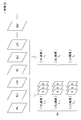
- FIG. 3 is a diagram illustrating an example of a multi-frame image and an image set mainly captured in the multi-frame shooting mode.
- FIG. 4 is a schematic diagram showing a typical configuration example of a convolutional neural network which is one of the learning models constituting the recognizer 15.
- FIG. 5 is a schematic diagram showing a configuration example of the intermediate layer 15B of the CNN 15 shown in FIG.
- FIG. 6 is a block diagram showing a main configuration used for explaining the operation of the endoscope system 10 according to the present invention.
- FIG. 1 is a perspective view showing an appearance of an endoscope system 10 according to the present invention.
- FIG. 2 is a block diagram illustrating an electrical configuration of the endoscope system 10.
- FIG. 3 is a diagram illustrating an example of a multi-frame image and an image set mainly
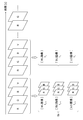
- FIG. 7 is a diagram illustrating an example of an image set including an R image, a G image, a B image, and a V image captured in a frame sequential manner.
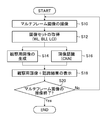
- FIG. 8 is a flowchart showing an embodiment of the image processing method according to the present invention.
- FIG. 1 is a perspective view showing an appearance of an endoscope system 10 according to the present invention.
- an endoscope system 10 mainly includes an endoscope (here, a flexible endoscope) 11 for imaging an observation target in a subject, a light source device 12, an endoscope processor 13, It comprises a display unit (display) 14 such as a liquid crystal monitor and a recognizer 15.
- an endoscope here, a flexible endoscope
- a light source device 12 for imaging an observation target in a subject
- an endoscope processor 13 It comprises a display unit (display) 14 such as a liquid crystal monitor and a recognizer 15.
- the light source device 12 supplies the endoscope 11 with various kinds of observation light such as white light for capturing a normal light image and light in a specific wavelength band for capturing a special light image.
- the endoscope processor 13 has an image processing function of generating image data of a normal light image for display / recording, a special light image, or an image for observation based on an image signal obtained by the endoscope 11, and a light source. It has a function of controlling the device 12, a function of displaying a normal image or an image for observation, and a function of displaying a recognition result by the recognizer 15 on the display 14. Although the details of the recognizer 15 will be described later, the endoscope processor 13 accepts an endoscopic image, detects the position of a region of interest (lesion, surgical scar, treatment scar, treatment tool, etc.) with respect to the endoscopic image, and detects the lesion. It is a part that performs recognition such as discrimination of the type.
- the display 14 displays a normal image, a special light image or an image for observation, and a recognition result by the recognizer 15 based on display image data input from the endoscope processor 13.
- the endoscope 11 is connected to a flexible insertion portion 16 to be inserted into a subject and a base end of the insertion portion 16, and is used for gripping the endoscope 11 and operating the insertion portion 16. And a universal cord 18 that connects the hand operation unit 17 to the light source device 12 and the endoscope processor 13.
- the illumination lens 42, the objective lens 44, the imaging element 45, and the like are built in the insertion portion tip 16a, which is the tip of the insertion portion 16 (see FIG. 2).
- a bending portion 16b that can freely bend is connected to the rear end of the insertion portion front end portion 16a.
- a flexible tube portion 16c having flexibility is connected to the rear end of the curved portion 16b.
- the hand operation unit 17 is provided with an angle knob 21, an operation button 22, a forceps inlet 23, and the like.
- the angle knob 21 is rotated when adjusting the bending direction and the bending amount of the bending portion 16b.
- the operation button 22 is used for various operations such as air supply / water supply and suction.
- the forceps inlet 23 communicates with a forceps channel in the insertion section 16.
- the hand operation unit 17 is provided with an endoscope operation unit 46 (see FIG. 2) for performing various settings.
- the universal cord 18 incorporates an air / water channel, a signal cable, a light guide, and the like.
- the distal end of the universal cord 18 is provided with a connector 25a connected to the light source device 12 and a connector 25b connected to the endoscope processor 13. Thereby, observation light is supplied from the light source device 12 to the endoscope scope 11 via the connector section 25a, and an image signal obtained by the endoscope scope 11 is input to the endoscope processor 13 via the connector section 25b. Is done.
- the light source device 12 is provided with a light source operation unit 12a such as a power button, a lighting button for turning on the light source, and a brightness adjustment button.
- the endoscope processor 13 includes a power button, a mouse (not shown), and the like. Is provided with a processor operation unit 13a including an input unit for receiving an input from the pointing device.
- the endoscope processor 13 and the light source device 12 of this example are of a separate type, the endoscope processor may be of a type with a built-in light source device.
- FIG. 2 is a block diagram illustrating an electrical configuration of the endoscope system 10.
- the endoscope scope 11 is roughly divided into a light guide 40, an illumination lens 42, an objective lens 44, an image sensor 45, an endoscope operation unit 46, and an endoscope control unit 47.
- ROM Read Only Memory
- the light guide 40 uses a large-diameter optical fiber, a bundle fiber, or the like.
- the light guide 40 has an incident end inserted into the light source device 12 via the connector portion 25a, and an emission end thereof passes through the insertion portion 16 and faces an illumination lens 42 provided in the insertion portion distal end portion 16a. ing.
- the illumination light supplied from the light source device 12 to the light guide 40 is applied to the observation target through the illumination lens 42. Then, the illumination light reflected and / or scattered by the observation target enters the objective lens 44.
- the objective lens 44 forms reflected light or scattered light (that is, an optical image of an observation target) of the incident illumination light on the imaging surface of the imaging element 45.
- the image sensor 45 is a complementary metal oxide semiconductor (CMOS) or charge coupled device (CCD) type image sensor, and is positioned and fixed relatively to the objective lens 44 at a position deeper than the objective lens 44.
- CMOS complementary metal oxide semiconductor
- CCD charge coupled device
- a plurality of pixels constituted by a plurality of photoelectric conversion elements (photodiodes) for photoelectrically converting an optical image are two-dimensionally arranged on an imaging surface of the imaging element 45.
- red (R), green (G), and blue (B) color filters are arranged for each pixel on the incident surface side of the plurality of pixels of the image sensor 45 of the present example, whereby the R pixel and the G pixel are arranged.
- B pixels The filter array of the RGB color filters is generally a Bayer array, but is not limited to this.
- the imaging element 45 converts the optical image formed by the objective lens 44 into an electric image signal and outputs it to the endoscope processor 13.
- an A / D (Analog / Digital) converter is built in, and a digital image signal is directly output from the image sensor 45 to the endoscope processor 13. You.
- an image signal output from the image sensor 45 is converted into a digital image signal by an A / D converter or the like (not shown). Is output.
- the endoscope operation unit 46 has a shooting mode setting unit that sets any one of a still image shooting button (not shown), a normal light image shooting mode, a special light image shooting mode, and a multi-frame shooting mode. ing.
- the photographing mode setting unit may be provided in the processor operation unit 13a of the endoscope processor 13.
- the endoscope control unit 47 sequentially executes various programs and data read from the ROM 48 or the like in accordance with an operation on the endoscope operation unit 46, and mainly controls the driving of the imaging element 45.
- the endoscope control unit 47 controls the image sensor 45 to read out the signals of the R pixel, the G pixel, and the B pixel of the image sensor 45, and performs the special light image capturing mode or the multi In the frame photographing mode, when the V-LED 32a emits purple light as the observation light in order to acquire a specific special light image, or when the B-LED 32b emits blue light, these purple lights are emitted.
- Only the signal of the B pixel of the image sensor 45 having the spectral sensitivity in the wavelength band of light and blue light is read out, or one of the three color pixels of the R pixel, the G pixel, and the B pixel, or 2
- the image sensor 45 is controlled to read out one color pixel.
- the endoscope control unit 47 communicates with the processor control unit 61 of the endoscope processor 13, and operates the endoscope scope 11 stored in the ROM 48 and the operation information of the endoscope operation unit 46.
- the identification information for identifying the type is transmitted to the endoscope processor 13.
- the light source device 12 has a light source control unit 31 and a light source unit 32.
- the light source control unit 31 performs communication between the control of the light source unit 32 and the processor control unit 61 of the endoscope processor 13 to exchange various information.
- the light source unit 32 has, for example, a plurality of semiconductor light sources.
- the light source unit 32 includes a V-LED (Violet Light Emitting Diode) 32a, a B-LED (Blue Light Emitting Diode) 32b, a G-LED (Green Light Emitting Diode) 32c, and an R-LED (Red Light).
- Emitting (Diode) 32d has four color LEDs.
- the V-LED 32a, the B-LED 32b, the G-LED 32c, and the R-LED 32d are, for example, observation lights having peak wavelengths at 410 nm, 450 nm, 530 nm, and 615 nm, respectively, and include violet (V) light, blue (B) light, It is a semiconductor light source that emits green (G) light and red (R) light.
- the light source control unit 31 individually controls the on / off of the four LEDs of the light source unit 32, the light emission amount at the time of lighting, and the like for each LED according to the shooting mode set by the shooting mode setting unit.
- the light source control unit 31 turns on all of the V-LED 32a, the B-LED 32b, the G-LED 32c, and the R-LED 32d. Therefore, in the normal light image capturing mode, white light including V light, B light, G light, and R light is used as observation light.
- the light source control unit 31 turns on any one of the V-LED 32a, the B-LED 32b, the G-LED 32c, and the R-LED 32d, or a plurality of light sources appropriately combined.
- the light emission amount (light amount ratio) of each light source is controlled, whereby images of a plurality of layers having different depths of the subject can be captured.
- the multi-frame shooting mode is a shooting mode in which a normal light image and one or more special light images are switched and photographed for each frame, or two or more special light images are switched and photographed for each frame.
- the light source control unit 31 causes the light source unit 32 to emit different observation light for each frame.
- each color emitted from each of the LEDs 32a to 32d is incident on a light guide 40 inserted into the endoscope 11 through an optical path coupling portion formed by a dichroic mirror, a lens, and the like, and a diaphragm mechanism (not shown). Is done.
- the observation light of the light source device 12 may be white light (light in a white wavelength band or light in a plurality of wavelength bands), light having a peak in one or more specific wavelength bands (special light), or a light having a peak in one or more specific wavelength bands. Light of various wavelength bands according to the observation purpose, such as a combination, is selected.
- a first example of the specific wavelength band is, for example, a blue band or a green band in a visible region.
- the wavelength band of the first example includes a wavelength band of 390 nm to 450 nm or 530 nm to 550 nm, and the light of the first example has a peak wavelength in the wavelength band of 390 nm to 450 nm or 530 nm to 550 nm. .
- the second example of the specific wavelength band is, for example, a red band in a visible region.
- the wavelength band of the second example includes a wavelength band of 585 nm to 615 nm or 610 nm to 730 nm, and the light of the second example has a peak wavelength in the wavelength band of 585 nm to 615 nm or 610 nm to 730 nm. .
- the third example of the specific wavelength band includes a wavelength band in which the extinction coefficient differs between oxyhemoglobin and reduced hemoglobin, and the light of the third example has a peak wavelength in a wavelength band in which the extinction coefficient differs between oxyhemoglobin and reduced hemoglobin.
- the wavelength band of the third example includes 400 ⁇ 10 nm, 440 ⁇ 10 nm, 470 ⁇ 10 nm, or a wavelength band of 600 nm or more and 750 nm or less, and the light of the third example includes the above 400 ⁇ 10 nm, 440 ⁇ 10 nm, 470 nm. It has a peak wavelength in a wavelength band of ⁇ 10 nm, or 600 nm to 750 nm.
- the fourth example of the specific wavelength band is a wavelength band (390 nm to 470 nm) of excitation light used for observation of fluorescence emitted from a fluorescent substance in a living body (fluorescence observation) and for exciting this fluorescent substance.
- the fifth example of the specific wavelength band is a wavelength band of infrared light.
- the wavelength band of the fifth example includes a wavelength band of 790 nm to 820 nm or 905 nm to 970 nm, and the light of the fifth example has a peak wavelength in a wavelength band of 790 nm to 820 nm or 905 nm to 970 nm.
- the endoscope processor 13 includes a processor operation unit 13a, a processor control unit 61, a ROM 62, a digital signal processing circuit (DSP: Digital Signal Processor) 63, an image processing unit 65, a display control unit 66, a storage unit 67, and the like. ing.
- DSP Digital Signal Processor
- the processor operation unit 13a includes a power button, an input unit for receiving inputs such as a coordinate position indicated on the screen of the display unit 14 by a mouse and a click (execution instruction).
- the processor control unit 61 reads out necessary programs and data from the ROM 62 according to the operation information at the processor operation unit 13a and the operation information at the endoscope operation unit 46 received via the endoscope control unit 47, By performing the sequential processing, each part of the endoscope processor 13 is controlled, and the light source device 12 is controlled.
- the processor control unit 61 may receive a necessary instruction input from another external device such as a keyboard connected via an interface (not shown).
- the DSP 63 which functions as one mode of an image acquisition unit that acquires image data of each frame of a moving image output from the endoscope 11 (the imaging element 45), is controlled by the processor control unit 61. Performs various signal processing such as defect correction processing, offset processing, white balance correction, gamma correction, and demosaicing processing (also referred to as “simultaneous processing”) on image data for one frame of a moving image input from Image data for one frame is generated.
- various signal processing such as defect correction processing, offset processing, white balance correction, gamma correction, and demosaicing processing (also referred to as “simultaneous processing”) on image data for one frame of a moving image input from Image data for one frame is generated.
- the image processing unit 65 receives image data from the DSP 63, performs image processing such as color conversion processing, color emphasis processing, and structure emphasis processing on the input image data as necessary, to capture the observation target.
- Image data representing an endoscope image is generated.
- the color conversion process is a process of performing color conversion on image data by 3 ⁇ 3 matrix processing, gradation conversion processing, three-dimensional lookup table processing, or the like.
- the color emphasis process is a process of emphasizing the color of the image data that has been subjected to the color conversion process, for example, in a direction that makes a difference in the color of blood vessels and mucous membranes.
- the structure emphasis process is a process of emphasizing a specific tissue or structure included in an observation target such as a blood vessel or a pit pattern, and is performed on image data after the color emphasis process.
- the image data of each frame of the moving image processed by the image processing unit 65 is recorded in the storage unit 67 as a still image or a moving image instructed to be shot when a shooting instruction of a still image or a moving image is issued.
- the display control unit 66 generates display data for displaying the normal light image or the special light image on the display unit 14 based on the image data input from the image processing unit 65, and displays the generated display data on the display unit 14. And the display device 14 displays a display image (such as a moving image captured by the endoscope 11).
- the display control unit 66 sets any one of the plurality of images. (A part of the image) is displayed on the display unit 14, or the observation image calculated by the image processing unit 65 using the plurality of images is displayed on the display unit 14.
- the display controller 66 causes the display 14 to display a recognition result input from the recognizer 15 via the image processor 65 or a recognition result input from the recognizer 15.
- the display control unit 66 displays an index indicating the target area so as to be superimposed on the image displayed on the display 14. For example, highlighting such as changing the color of the region of interest in the display image, displaying a marker, and displaying a bounding box can be considered as indices.
- the display control unit 66 can display information indicating the presence or absence of the attention area based on the detection result of the attention area by the recognizer 15 so as not to overlap the image displayed on the display 14.
- the information indicating the presence / absence of the attention area includes, for example, changing the color of the frame of the endoscope image between the case where the attention area is detected and the case where the attention area is not detected, and the method of displaying the text “attention area exists!” A mode in which the image is displayed in a display area different from the endoscope image is considered.
- the display controller 66 causes the display 14 to display the discrimination result.
- a display method of the discrimination result for example, display of text indicating the detection result on a display image of the display unit 14 or the like can be considered.
- the display of the text need not be on the display image, and is not particularly limited as long as the correspondence between the text and the display image is understood.
- the recognizer 15 receives the image after the image processing by the endoscope processor 13. First, the recognition image received by the recognizer 15 will be described.
- the recognizer 15 of this example is applied when the multi-frame shooting mode is set.
- the light source device 12 When the multi-frame shooting mode is set, the light source device 12 outputs white light including violet light, blue light, green light, and red light, and V-LED 32a, B-LED 32b, G-LED 32c, and R-LED 32d.
- Light (special light) of one or a plurality of specific wavelength bands whose lighting is controlled is sequentially generated, and the endoscope processor 13 outputs an image (normal light image) under white light from the endoscope 11 and a special light. Images under light (special light images) are sequentially acquired.
- a normal light image (WL (White @ Light) image) as the first endoscope image and two types of special light images as the second endoscope image.
- BLI Blue Light Imaging or Blue LASER Imaging
- LCI Linked Color Imaging
- the BLI image and the LCI image are images captured with the BLI observation light and the LCI observation light, respectively.
- the observation light for BLI is observation light in which the ratio of V light having a high absorptivity in surface blood vessels is high and the ratio of G light having a high absorptivity in middle blood vessels is suppressed. It is suitable for generating an image (BLI image) suitable for structure enhancement.
- the observation light for LCI has a higher ratio of the V light than the observation light for WL, and is an observation light suitable for capturing a minute change in color tone as compared with the observation light for WL.
- This is an image that has been subjected to a color enhancement process using the signal of the R component so that the reddish color becomes redder and the whitish color becomes more white, centering on the color near the mucous membrane.
- the recognizer 15 receives an image set Sa including a plurality of images (in this example, a WL image, a BLI image, and an LCI image) sequentially acquired by the endoscope processor 13 as images for recognition.
- the recognizer 15 sequentially inputs the image sets Sa. Since the image set Sa is composed of three consecutive frames (WL image, BLI image, and LCI image) in chronological order, each image set Sa Is equivalent to three frames of each frame imaged in the multi-frame shooting mode. That is, the time interval between the image set Sa at the time t n and the image set Sa at the previous time t n ⁇ 1 received by the recognizing unit 15 is equivalent to three frames of each frame captured in the multi-frame shooting mode. Equivalent to time.
- FIG. 4 is a schematic diagram showing a typical configuration example of a convolutional neural network (CNN: Convolutional Neural Network), which is one of the learning models constituting the recognizer 15.
- CNN Convolutional Neural Network
- the CNN 15 is, for example, a learning model for detecting the position of a region of interest (lesion, surgical mark, treatment mark, treatment tool, etc.) in the endoscope image and discriminating the type of lesion, and has a plurality of layer structures. , And holds a plurality of weight parameters.
- the CNN 15 becomes a trained model when the weight parameter is set to the optimum value, and functions as a recognizer.
- the CNN 15 includes an input layer 15A, an intermediate layer 15B having a plurality of convolutional layers and a plurality of pooling layers, and an output layer 15C.
- an input layer 15A an intermediate layer 15B having a plurality of convolutional layers and a plurality of pooling layers
- an output layer 15C In each layer, a plurality of "nodes" are connected by “edges”. The structure is
- the CNN 15 of the present example is a learning model for performing segmentation for recognizing the position of a region of interest in an endoscope image.
- a full-layer convolution network (FCN), which is a type of CNN, is applied to the CNN 15.
- FCN full-layer convolution network
- the position of the attention area in the endoscope image can be grasped at the pixel level.
- the image set Sa for recognition (FIG. 3) is input to the input layer 15A.
- the intermediate layer 15B is a part for extracting features from the image set Sa input from the input layer 15A.
- the convolutional layer in the intermediate layer 15B performs a filtering process on a nearby node in the image set Sa or the previous layer (performs a convolution operation using a filter) to obtain a “feature map”.
- the pooling layer reduces (or enlarges) the feature map output from the convolutional layer to create a new feature map.
- the “convolution layer” has a role of extracting features such as edge extraction from an image, and the “pooling layer” has a role of providing robustness so that the extracted features are not affected by translation or the like.
- the intermediate layer 15B is not limited to the case where the convolutional layer and the pooling layer are set as one set, but may include a case where the convolutional layer is continuous or a normalization layer.
- the output layer 15C is a part that outputs a recognition result for detecting the position of the attention area in the endoscope image and classifying (discriminating) the type of lesion based on the features extracted by the intermediate layer 15B.
- the CNN 15 is learned from a large number of sets of a learning image set Sa and correct data for the image set Sa.
- the coefficients and offset values of the filter applied to each convolutional layer of the CNN 15 are determined by learning. Is set to the optimal value by the data set for
- the correct answer data is preferably a region of interest or a discrimination result specified by a doctor with respect to an endoscopic image (in this example, at least one image of the image set Sa).
- FIG. 5 is a schematic diagram showing a configuration example of the intermediate layer 15B of the CNN 15 shown in FIG.
- the convolution layer of the first (1st) of the region of interest, and the image set Sa for recognition, the convolution operation of the filter F 1 is performed.
- the image set Sa is N (N-channel) images having an image size of H vertically and W horizontally.
- the image set Sa is an image of 9 channels.
- Filter F 1 of this are image set Sa and convolution operation, since the image set S is N-channel (N sheets), for example, in the case of the filter size 5, the filter size will filter 5 ⁇ 5 ⁇ N.
- Filter F 1 used in the second convolution layer for example, in the case of size 3 filter, the filter size will filter 3 ⁇ 3 ⁇ M.
- the size of the “feature map” in the n-th convolutional layer is smaller than the size of the “feature map” in the second convolutional layer because the downscaling is performed by the convolutional layers up to the previous stage.
- the convolutional layer in the first half of the intermediate layer 15B is responsible for extraction of feature values, and the convolutional layer in the second half is responsible for segmentation of the object (region of interest).
- the convolution layer in the latter half upscaling is performed, and in the last convolution layer, one “feature map” having the same size as the input image set Sa is obtained.
- the output layer 15C (FIG. 4) of the CNN 15 grasps the position of the attention area in the image of the image set Sa at the pixel level by using the “feature map” obtained from the intermediate layer 15B. That is, it is possible to detect whether each pixel of the endoscope image belongs to the attention area and output the detection result.
- a plurality of images (WL) sequentially acquired in the multi-frame shooting mode are compared with a case where recognition is performed using any one (one type) of the WL image, the BLI image, and the LCI image.
- Image, a BLI image, and an LCI image the recognition accuracy can be improved.
- the CNN 15 of the present example recognizes the position of the attention area in the endoscope image, but the recognizer (CNN) according to the present invention is not limited to this, and performs discrimination regarding a lesion. Output the discrimination result.
- the recognizer classifies the endoscope image into three categories of “neoplastic”, “non-neoplastic”, and “other”, and discriminates the result as “neoplastic”, “non-neoplastic”, and “other” May be output as three scores (the total of the three scores is 100%), or if the three scores can be clearly classified, a classification result may be output.
- a CNN having a fully connected layer as the last one or more layers of the intermediate layer is preferable instead of the full-layer convolutional network (FCN).
- FIG. 6 is a block diagram showing a main configuration used for explaining the operation of the endoscope system 10 according to the present invention.
- observation light (V light, B light, G light, and R light) having different peak wavelengths are respectively transmitted to the light guide 40.
- the subject 20 is irradiated via the. Since the V light, the B light, the G light, and the R light respectively reach a plurality of layers at different depths of the subject 20, images of the subject 20 at different depths can be captured by these observation lights.
- a plurality of different observation lights for example, first observation light for WL, second observation light for BLI, and third observation light for LCI
- An image, a BLI image, and an LCI image are sequentially acquired, but the observation light for WL, BLI, and LCI has different light intensity ratios of V light, B light, G light, and R light as described above. It is.
- a WL image, a BLI image, and an LCI image are sequentially and repeatedly captured by irradiation of a plurality of different observation lights. Since the WL image, the BLI image, and the LCI image are each a color image, the endoscope processor 13 generates an RGB three-channel WL image, a BLI image, and an LCI image.
- the recognizer 15 receives an image set Sa (images of 9 channels in total) including a WL image, a BLI image, and an LCI image as images for recognition.
- the recognizer 15 detects the position of the region of interest (in this example, the lesion region) in the endoscope image, and outputs position information (recognition result) indicating the lesion region to the endoscope processor 13.
- the image processing unit 65 of the endoscope processor 13 generates a WL image, a BLI image, and an LCI image from an image signal input from the endoscope 11 and also generates an observation image.
- a part of a plurality of images for example, a WL image among a WL image, a BLI image, and an LCI image
- an image calculated using the plurality of images (the WL image)
- An image obtained by combining two or more images of the BLI image and the LCI image) may be used as the observation image.
- the observation images are preferably one type of image.
- the display control unit 66 inputs the observation image from the image processing unit 65, inputs the position information indicating the lesion area from the recognizing device 15, and causes the display device 14 to display the observation image and the recognition result.
- the display control unit 66 displays the observation image 26 on the display device 14 and performs an emphasis process for emphasizing the recognized attention area (lesion area).
- the lesion area is highlighted by superimposing and displaying the index 28 indicating the lesion area on the observation image 26 displayed on the display unit 14.
- the display of the index 28 in addition to highlighting such as changing the color of the lesion area, display of a boundary line indicating the outline of the lesion area, display of a marker indicating the lesion area, and display of a bounding box can be considered.
- the recognizer 15 of the present example recognizes the position of the attention area in the endoscope image.
- the present invention is not limited to this, and the recognizer 15 may execute a discrimination regarding a lesion and output a discrimination result.
- a display method of the discrimination result for example, a method of displaying text indicating the discrimination result on the image of the display unit 14 is conceivable.
- the display position of the text need not be on the image, and may be a window different from the image as long as the correspondence between the text and the image is understood, and is not particularly limited.
- the monochrome image sensor converts the light into R light, G light, B light, and V light.
- the R, G, B, and V images of the corresponding colors are picked up in a frame-sequential manner.
- FIG. 7 is a diagram showing an example of an image set including an R image, a G image, a B image, and a V image, which are imaged in a frame sequential manner.
- the endoscope processor 13 includes a plurality of images (R image, G image, B image, and V image) sequentially acquired using a plurality of different observation lights (R light, G light, B light, and V light).
- An observation image such as a WL image, a BLI image, and an LCI image can be generated. These observation images can be generated by adjusting the synthesis ratio of the R, G, B, and V images.
- An image set may include an image obtained by multiplying at least two images among the R image, the G image, the B image, and the V image by a preset coefficient and synthesizing (four arithmetic operations). For example, an image obtained by dividing each pixel by an image (V image) having a center wavelength of 410 nm and an image (B image) having a center wavelength of 450 nm, or an image (V image) having a center wavelength of 410 nm and an image (B image) having a center wavelength of 450 nm An image obtained by multiplying each pixel by (image) may be used.
- the recognizer 15 can receive the WL image, the BLI image, and the LCI image generated by the endoscope processor 13 as an image set Sb, and return a recognition result for the endoscope image to the endoscope processor 13.
- the recognizer 15 of this example accepts an image set Sa (images of 9 channels in total) including a WL image, a BLI image, and an LCI image as an image for recognition, but is not limited thereto.
- An image set including a G image, a B image, and a V image may be accepted, and a recognition result for an endoscopic image may be output.
- FIG. 8 is a flowchart showing an embodiment of the image processing method according to the present invention, and shows a processing procedure of each unit of the endoscope system 10 shown in FIG.
- the multi-frame shooting mode is set, and the endoscope 11 sequentially captures multi-frame images using a plurality of different observation lights (step S10).
- the endoscope processor 13 acquires an image set constituting a multi-frame image captured by the endoscope 11 (step S12, first step).
- the image set includes a WL image, a BLI image, and an LCI image captured by observation light for WL, BLI, and LCI captured by the endoscope 11, or an R image and a G image captured in a frame-sequential manner.
- B image, and WL image, BLI image, and LCI image generated from the V image are conceivable, but the special light image may be any one of the BLI image and the LCI image, May be a special light image captured by the special light.
- the image set does not include the WL image (normal light image) but includes two or more special light images including the first special light image captured by the first special light and the second special light image captured by the second special light. It may be an optical image. In short, any image set may be used as long as it is an image set including a plurality of images sequentially acquired using a plurality of different observation lights, and may be any image set.
- the image processing unit 65 of the endoscope processor 13 generates an observation image based on the acquired image set (Step S14).
- the observation image is an image calculated using a part of a plurality of images (for example, a WL image among a WL image, a BLI image, and an LCI image) or a plurality of images.
- the recognizer 15 performs the position detection of the attention area shown in the endoscope image, the discrimination of the type of the lesion, and the like based on the image set received via the endoscope processor 13 and outputs the recognition result. (Step S16, second step).
- the display controller 66 causes the display 14 to display the generated observation image and the recognition result obtained by the recognizer 15 (step S18, third step).
- step S20 it is determined whether or not the imaging of the multi-frame image is to be ended. If the imaging of the multi-frame image is to be continued (in the case of “No”), the process transits to step S10 and proceeds to step S10. To step S20 are repeatedly performed. Thereby, the observation image is displayed as a moving image, and the recognition result of the recognizer 15 is also continuously displayed.
- the endoscope system 10 including the endoscope scope 11 and the like has been described.
- the present invention is not limited to the endoscope system 10, but includes the endoscope processor 13 and the recognizer 15.
- An image processing device may be used.
- the endoscope processor 13 and the recognizer 15 may be integrated or may be separate.
- the different observation lights are not limited to those emitted from the four-color LEDs.
- a blue laser diode that emits blue laser light having a center wavelength of 445 nm and a blue-violet laser diode that emits blue-violet laser light having a center wavelength of 405 nm May be used as a light source, and the laser light of the blue laser diode and the blue-violet laser diode may be emitted to a YAG (Yttrium Aluminum Aluminum Garnet) based phosphor to emit light.
- YAG Yttrium Aluminum Aluminum Garnet
- the blue-violet laser light is transmitted without exciting the phosphor. Therefore, by adjusting the intensity of the blue laser light and the blue-violet laser light, it is possible to irradiate the observation light for WL, the observation light for BLI, and the observation light for LCI. When only light is emitted, observation light having a center wavelength of 405 nm can be emitted.
- the observation image according to the present invention is not limited to a moving image, but may be a still image stored in the storage unit 67 or the like, and the recognizer may output a recognition result based on a still image set.
- the recognizer is not limited to the CNN, but may be a machine learning model other than the CNN, such as a DBN (Deep Belief Network) and an SVM (Support Vector Machine).
- DBN Deep Belief Network
- SVM Serial Vector Machine
- the hardware structure of the endoscope processor 13 and / or the recognizer 15 is various processors as described below.
- the circuit configuration can be changed after manufacturing such as CPU (Central Processing Unit) and FPGA (Field Programmable Gate Array), which are general-purpose processors that execute software (programs) and function as various control units.
- Special-purpose circuits such as a programmable logic device (Programmable Logic Device: PLD), an ASIC (Application Specific Integrated Circuit), and a dedicated electric circuit having a circuit configuration specifically designed to execute a specific process are included. It is.
- One processing unit may be configured by one of these various processors, or configured by two or more processors of the same or different types (for example, a plurality of FPGAs or a combination of a CPU and an FPGA). You may. Further, a plurality of control units may be configured by one processor. As an example of configuring a plurality of control units with one processor, first, as represented by a computer such as a client or a server, one processor is configured by a combination of one or more CPUs and software. There is a form in which a processor functions as a plurality of control units.
- SoC system-on-chip
- a form in which a processor that realizes the functions of the entire system including a plurality of control units by one IC (Integrated Circuit) chip is used. is there.
- the various control units are configured by using one or more of the various processors described above as a hardware structure.
Landscapes
- Health & Medical Sciences (AREA)
- Life Sciences & Earth Sciences (AREA)
- Physics & Mathematics (AREA)
- Surgery (AREA)
- Engineering & Computer Science (AREA)
- Optics & Photonics (AREA)
- Medical Informatics (AREA)
- General Health & Medical Sciences (AREA)
- Pathology (AREA)
- Nuclear Medicine, Radiotherapy & Molecular Imaging (AREA)
- Biomedical Technology (AREA)
- Heart & Thoracic Surgery (AREA)
- Biophysics (AREA)
- Molecular Biology (AREA)
- Animal Behavior & Ethology (AREA)
- Radiology & Medical Imaging (AREA)
- Public Health (AREA)
- Veterinary Medicine (AREA)
- General Physics & Mathematics (AREA)
- Astronomy & Astrophysics (AREA)
- Computer Vision & Pattern Recognition (AREA)
- Theoretical Computer Science (AREA)
- Endoscopes (AREA)
- Image Analysis (AREA)
Abstract
La présente invention concerne un dispositif de traitement d'image, un procédé et un système endoscopique au moyen desquels il est possible d'améliorer la précision de reconnaissance sur la base d'une pluralité d'images et au moyen desquels il est possible de présenter des images d'observation et des résultats de reconnaissance préférables. La présente invention comporte : un dispositif de reconnaissance (15) qui reçoit un ensemble d'images comprenant une pluralité d'images acquises séquentiellement à l'aide d'une pluralité de différents faisceaux d'observation et qui délivre un résultat de reconnaissance par rapport à l'ensemble d'images; et une unité de commande d'affichage (66), d'un processeur d'endoscope (13), pour amener à la fois un résultat de reconnaissance et une image d'observation calculés à l'aide de la totalité ou d'une partie d'une pluralité d'images, à être affichés sur une unité d'affichage (14). Puisque le dispositif de reconnaissance (15) reçoit un ensemble d'images acquises séquentiellement à l'aide d'une pluralité de différents faisceaux d'observation et acquiert un résultat de reconnaissance par rapport à l'ensemble d'images, il est possible d'améliorer la précision de reconnaissance par comparaison avec le cas où une reconnaissance d'image est effectuée sur la base d'une seule image acquise à l'aide d'un seul faisceau d'observation.
Priority Applications (2)
| Application Number | Priority Date | Filing Date | Title |
|---|---|---|---|
| JP2020528760A JP7289296B2 (ja) | 2018-07-05 | 2019-06-13 | 画像処理装置、内視鏡システム及び画像処理装置の作動方法 |
| JP2022168121A JP7542585B2 (ja) | 2018-07-05 | 2022-10-20 | 画像処理装置、内視鏡システム及び画像処理装置の作動方法 |
Applications Claiming Priority (2)
| Application Number | Priority Date | Filing Date | Title |
|---|---|---|---|
| JP2018-128168 | 2018-07-05 | ||
| JP2018128168 | 2018-07-05 |
Publications (1)
| Publication Number | Publication Date |
|---|---|
| WO2020008834A1 true WO2020008834A1 (fr) | 2020-01-09 |
Family
ID=69059546
Family Applications (1)
| Application Number | Title | Priority Date | Filing Date |
|---|---|---|---|
| PCT/JP2019/023492 Ceased WO2020008834A1 (fr) | 2018-07-05 | 2019-06-13 | Dispositif de traitement d'image, procédé et système endoscopique |
Country Status (2)
| Country | Link |
|---|---|
| JP (2) | JP7289296B2 (fr) |
| WO (1) | WO2020008834A1 (fr) |
Cited By (10)
| Publication number | Priority date | Publication date | Assignee | Title |
|---|---|---|---|---|
| JP2021125056A (ja) * | 2020-02-07 | 2021-08-30 | カシオ計算機株式会社 | 識別装置、識別器学習方法、識別方法及びプログラム |
| JP2022018842A (ja) * | 2020-07-16 | 2022-01-27 | 富士フイルム株式会社 | 内視鏡システム及びその作動方法 |
| JP2022038390A (ja) * | 2020-08-26 | 2022-03-10 | 株式会社東芝 | 推論装置、方法、プログラムおよび学習装置 |
| CN114830107A (zh) * | 2020-03-10 | 2022-07-29 | 奥林巴斯株式会社 | 图像处理系统、图像处理装置、内窥镜系统、接口以及图像处理方法 |
| JPWO2023281607A1 (fr) * | 2021-07-05 | 2023-01-12 | ||
| WO2023007896A1 (fr) * | 2021-07-28 | 2023-02-02 | 富士フイルム株式会社 | Système endoscope, dispositif de traitement, et procédé de fonctionnement associé |
| WO2023026538A1 (fr) * | 2021-08-27 | 2023-03-02 | ソニーグループ株式会社 | Système d'assistance médicale, procédé d'assistance médicale et dispositif d'assistance à l'évaluation |
| JP2023525967A (ja) * | 2020-05-20 | 2023-06-20 | クアンタム サージカル | 画像分析によって病変部の再発を予測するための方法 |
| JP2023526909A (ja) * | 2020-05-20 | 2023-06-26 | クアンタム サージカル | ディープラーニングに基づいてアブレーション領域を決定する方法 |
| WO2024166731A1 (fr) * | 2023-02-07 | 2024-08-15 | 富士フイルム株式会社 | Dispositif de traitement d'images, endoscope, procédé de traitement d'images, et programme |
Citations (2)
| Publication number | Priority date | Publication date | Assignee | Title |
|---|---|---|---|---|
| WO2017175282A1 (fr) * | 2016-04-04 | 2017-10-12 | オリンパス株式会社 | Procédé d'apprentissage, dispositif de reconnaissance d'image et programme |
| WO2019088121A1 (fr) * | 2017-10-30 | 2019-05-09 | 公益財団法人がん研究会 | Appareil d'aide au diagnostic d'image, procédé de collecte de données, procédé d'aide au diagnostic d'image et programme d'assistance au diagnostic d'image |
Family Cites Families (6)
| Publication number | Priority date | Publication date | Assignee | Title |
|---|---|---|---|---|
| EP2008573B1 (fr) | 2006-04-20 | 2017-05-31 | Olympus Corporation | Système d'observation biologique |
| JP6140056B2 (ja) * | 2013-09-26 | 2017-05-31 | 富士フイルム株式会社 | 内視鏡システム、内視鏡システムのプロセッサ装置、内視鏡システムの作動方法、プロセッサ装置の作動方法 |
| JP6602969B2 (ja) | 2016-05-23 | 2019-11-06 | オリンパス株式会社 | 内視鏡画像処理装置 |
| JP6927211B2 (ja) | 2016-07-04 | 2021-08-25 | 日本電気株式会社 | 画像診断学習装置、画像診断装置、方法およびプログラム |
| CN110049709B (zh) | 2016-12-07 | 2022-01-11 | 奥林巴斯株式会社 | 图像处理装置 |
| JP6751773B2 (ja) * | 2016-12-07 | 2020-09-09 | オリンパス株式会社 | 画像処理装置及び画像処理装置の作動方法 |
-
2019
- 2019-06-13 WO PCT/JP2019/023492 patent/WO2020008834A1/fr not_active Ceased
- 2019-06-13 JP JP2020528760A patent/JP7289296B2/ja active Active
-
2022
- 2022-10-20 JP JP2022168121A patent/JP7542585B2/ja active Active
Patent Citations (2)
| Publication number | Priority date | Publication date | Assignee | Title |
|---|---|---|---|---|
| WO2017175282A1 (fr) * | 2016-04-04 | 2017-10-12 | オリンパス株式会社 | Procédé d'apprentissage, dispositif de reconnaissance d'image et programme |
| WO2019088121A1 (fr) * | 2017-10-30 | 2019-05-09 | 公益財団法人がん研究会 | Appareil d'aide au diagnostic d'image, procédé de collecte de données, procédé d'aide au diagnostic d'image et programme d'assistance au diagnostic d'image |
Non-Patent Citations (1)
| Title |
|---|
| IWAHORI, YUJI ET AL.: "Classification and size & shape recovery from endscope image for supporting medical diagnosis", SOGO KOGAKU, vol. 30, 31 March 2018 (2018-03-31), pages 18 - 36, ISSN: 0915-3292 * |
Cited By (21)
| Publication number | Priority date | Publication date | Assignee | Title |
|---|---|---|---|---|
| US11295443B2 (en) | 2020-02-07 | 2022-04-05 | Casio Computer Co., Ltd. | Identification apparatus, identifier training method, identification method, and recording medium |
| JP2021125056A (ja) * | 2020-02-07 | 2021-08-30 | カシオ計算機株式会社 | 識別装置、識別器学習方法、識別方法及びプログラム |
| JP7044120B2 (ja) | 2020-02-07 | 2022-03-30 | カシオ計算機株式会社 | 識別装置、識別器学習方法、識別方法及びプログラム |
| CN114830107A (zh) * | 2020-03-10 | 2022-07-29 | 奥林巴斯株式会社 | 图像处理系统、图像处理装置、内窥镜系统、接口以及图像处理方法 |
| JP2023525967A (ja) * | 2020-05-20 | 2023-06-20 | クアンタム サージカル | 画像分析によって病変部の再発を予測するための方法 |
| JP2023526909A (ja) * | 2020-05-20 | 2023-06-26 | クアンタム サージカル | ディープラーニングに基づいてアブレーション領域を決定する方法 |
| JP7834030B2 (ja) | 2020-05-20 | 2026-03-23 | クアンタム サージカル | ディープラーニングに基づいてアブレーション領域を決定する方法 |
| JP7796041B2 (ja) | 2020-05-20 | 2026-01-08 | クアンタム サージカル | 画像分析によって病変部の再発を予測するための方法 |
| US12357232B2 (en) | 2020-05-20 | 2025-07-15 | Quantum Surgical | Method for predicting the recurrence of a lesion by image analysis |
| JP7411515B2 (ja) | 2020-07-16 | 2024-01-11 | 富士フイルム株式会社 | 内視鏡システム及びその作動方法 |
| JP2022018842A (ja) * | 2020-07-16 | 2022-01-27 | 富士フイルム株式会社 | 内視鏡システム及びその作動方法 |
| JP2022038390A (ja) * | 2020-08-26 | 2022-03-10 | 株式会社東芝 | 推論装置、方法、プログラムおよび学習装置 |
| JP7481956B2 (ja) | 2020-08-26 | 2024-05-13 | 株式会社東芝 | 推論装置、方法、プログラムおよび学習装置 |
| CN117241719A (zh) * | 2021-07-05 | 2023-12-15 | 奥林巴斯医疗株式会社 | 内窥镜处理器、内窥镜装置以及诊断用图像生成方法 |
| JP7592165B2 (ja) | 2021-07-05 | 2024-11-29 | オリンパスメディカルシステムズ株式会社 | 内視鏡プロセッサ、内視鏡装置、および内視鏡装置の作動方法 |
| US12469247B2 (en) | 2021-07-05 | 2025-11-11 | Olympus Medical Systems Corp. | Endoscope processor, endoscope device, and method of generating diagnostic image |
| WO2023281607A1 (fr) * | 2021-07-05 | 2023-01-12 | オリンパスメディカルシステムズ株式会社 | Processeur d'endoscope, dispositif d'endoscope, et procédé de génération d'une image de diagnostic |
| JPWO2023281607A1 (fr) * | 2021-07-05 | 2023-01-12 | ||
| WO2023007896A1 (fr) * | 2021-07-28 | 2023-02-02 | 富士フイルム株式会社 | Système endoscope, dispositif de traitement, et procédé de fonctionnement associé |
| WO2023026538A1 (fr) * | 2021-08-27 | 2023-03-02 | ソニーグループ株式会社 | Système d'assistance médicale, procédé d'assistance médicale et dispositif d'assistance à l'évaluation |
| WO2024166731A1 (fr) * | 2023-02-07 | 2024-08-15 | 富士フイルム株式会社 | Dispositif de traitement d'images, endoscope, procédé de traitement d'images, et programme |
Also Published As
| Publication number | Publication date |
|---|---|
| JPWO2020008834A1 (ja) | 2021-06-24 |
| JP7289296B2 (ja) | 2023-06-09 |
| JP7542585B2 (ja) | 2024-08-30 |
| JP2022189900A (ja) | 2022-12-22 |
Similar Documents
| Publication | Publication Date | Title |
|---|---|---|
| JP7542585B2 (ja) | 画像処理装置、内視鏡システム及び画像処理装置の作動方法 | |
| US12303097B2 (en) | Medical image processing apparatus, endoscope system, and medical image processing method | |
| JP7135082B2 (ja) | 内視鏡装置、内視鏡装置の作動方法、及びプログラム | |
| JP7374280B2 (ja) | 内視鏡装置、内視鏡プロセッサ、及び内視鏡装置の作動方法 | |
| CN112105284B (zh) | 图像处理装置、内窥镜系统及图像处理方法 | |
| US11948080B2 (en) | Image processing method and image processing apparatus | |
| US11957299B2 (en) | Endoscope image processing apparatus, endoscope image processing method, and program | |
| US12362061B2 (en) | Medical image processing device, processor device, endoscope system, medical image processing method, and program | |
| WO2020170809A1 (fr) | Dispositif de traitement d'image médicale, système d'endoscope et procédé de traitement d'image médicale | |
| JP7335399B2 (ja) | 医用画像処理装置及び内視鏡システム並びに医用画像処理装置の作動方法 | |
| WO2021199910A1 (fr) | Système de traitement d'image médicale et méthode d'exploitation de système de traitement d'image médicale | |
| CN115315210B (zh) | 图像处理装置、图像处理方法、导航方法以及内窥镜系统 | |
| CN114627045A (zh) | 医用图像处理系统、医用图像处理系统的工作方法 | |
| WO2023007896A1 (fr) | Système endoscope, dispositif de traitement, et procédé de fonctionnement associé | |
| WO2021153471A1 (fr) | Dispositif de traitement d'image médicale, procédé de traitement d'image médicale et programme |
Legal Events
| Date | Code | Title | Description |
|---|---|---|---|
| 121 | Ep: the epo has been informed by wipo that ep was designated in this application |
Ref document number: 19830637 Country of ref document: EP Kind code of ref document: A1 |
|
| WWE | Wipo information: entry into national phase |
Ref document number: 2020528760 Country of ref document: JP |
|
| NENP | Non-entry into the national phase |
Ref country code: DE |
|
| 122 | Ep: pct application non-entry in european phase |
Ref document number: 19830637 Country of ref document: EP Kind code of ref document: A1 |