WO2020008873A1 - Dispositif de commande pour véhicules - Google Patents
Dispositif de commande pour véhicules Download PDFInfo
- Publication number
- WO2020008873A1 WO2020008873A1 PCT/JP2019/024209 JP2019024209W WO2020008873A1 WO 2020008873 A1 WO2020008873 A1 WO 2020008873A1 JP 2019024209 W JP2019024209 W JP 2019024209W WO 2020008873 A1 WO2020008873 A1 WO 2020008873A1
- Authority
- WO
- WIPO (PCT)
- Prior art keywords
- vehicle
- speed
- unit
- acceleration
- control device
- Prior art date
- Legal status (The legal status is an assumption and is not a legal conclusion. Google has not performed a legal analysis and makes no representation as to the accuracy of the status listed.)
- Ceased
Links
Images


Classifications
-
- B—PERFORMING OPERATIONS; TRANSPORTING
- B60—VEHICLES IN GENERAL
- B60W—CONJOINT CONTROL OF VEHICLE SUB-UNITS OF DIFFERENT TYPE OR DIFFERENT FUNCTION; CONTROL SYSTEMS SPECIALLY ADAPTED FOR HYBRID VEHICLES; ROAD VEHICLE DRIVE CONTROL SYSTEMS FOR PURPOSES NOT RELATED TO THE CONTROL OF A PARTICULAR SUB-UNIT
- B60W30/00—Purposes of road vehicle drive control systems not related to the control of a particular sub-unit, e.g. of systems using conjoint control of vehicle sub-units
- B60W30/18—Propelling the vehicle
- B60W30/19—Improvement of gear change, e.g. by synchronisation or smoothing gear shift
-
- B—PERFORMING OPERATIONS; TRANSPORTING
- B60—VEHICLES IN GENERAL
- B60L—PROPULSION OF ELECTRICALLY-PROPELLED VEHICLES; SUPPLYING ELECTRIC POWER FOR AUXILIARY EQUIPMENT OF ELECTRICALLY-PROPELLED VEHICLES; ELECTRODYNAMIC BRAKE SYSTEMS FOR VEHICLES IN GENERAL; MAGNETIC SUSPENSION OR LEVITATION FOR VEHICLES; MONITORING OPERATING VARIABLES OF ELECTRICALLY-PROPELLED VEHICLES; ELECTRIC SAFETY DEVICES FOR ELECTRICALLY-PROPELLED VEHICLES
- B60L15/00—Methods, circuits, or devices for controlling the traction-motor speed of electrically-propelled vehicles
- B60L15/20—Methods, circuits, or devices for controlling the traction-motor speed of electrically-propelled vehicles for control of the vehicle or its driving motor to achieve a desired performance, e.g. speed, torque, programmed variation of speed
- B60L15/209—Methods, circuits, or devices for controlling the traction-motor speed of electrically-propelled vehicles for control of the vehicle or its driving motor to achieve a desired performance, e.g. speed, torque, programmed variation of speed for overtaking
-
- B—PERFORMING OPERATIONS; TRANSPORTING
- B60—VEHICLES IN GENERAL
- B60L—PROPULSION OF ELECTRICALLY-PROPELLED VEHICLES; SUPPLYING ELECTRIC POWER FOR AUXILIARY EQUIPMENT OF ELECTRICALLY-PROPELLED VEHICLES; ELECTRODYNAMIC BRAKE SYSTEMS FOR VEHICLES IN GENERAL; MAGNETIC SUSPENSION OR LEVITATION FOR VEHICLES; MONITORING OPERATING VARIABLES OF ELECTRICALLY-PROPELLED VEHICLES; ELECTRIC SAFETY DEVICES FOR ELECTRICALLY-PROPELLED VEHICLES
- B60L15/00—Methods, circuits, or devices for controlling the traction-motor speed of electrically-propelled vehicles
- B60L15/20—Methods, circuits, or devices for controlling the traction-motor speed of electrically-propelled vehicles for control of the vehicle or its driving motor to achieve a desired performance, e.g. speed, torque, programmed variation of speed
- B60L15/2054—Methods, circuits, or devices for controlling the traction-motor speed of electrically-propelled vehicles for control of the vehicle or its driving motor to achieve a desired performance, e.g. speed, torque, programmed variation of speed by controlling transmissions or clutches
-
- B—PERFORMING OPERATIONS; TRANSPORTING
- B60—VEHICLES IN GENERAL
- B60W—CONJOINT CONTROL OF VEHICLE SUB-UNITS OF DIFFERENT TYPE OR DIFFERENT FUNCTION; CONTROL SYSTEMS SPECIALLY ADAPTED FOR HYBRID VEHICLES; ROAD VEHICLE DRIVE CONTROL SYSTEMS FOR PURPOSES NOT RELATED TO THE CONTROL OF A PARTICULAR SUB-UNIT
- B60W10/00—Conjoint control of vehicle sub-units of different type or different function
- B60W10/04—Conjoint control of vehicle sub-units of different type or different function including control of propulsion units
- B60W10/06—Conjoint control of vehicle sub-units of different type or different function including control of propulsion units including control of combustion engines
-
- B—PERFORMING OPERATIONS; TRANSPORTING
- B60—VEHICLES IN GENERAL
- B60W—CONJOINT CONTROL OF VEHICLE SUB-UNITS OF DIFFERENT TYPE OR DIFFERENT FUNCTION; CONTROL SYSTEMS SPECIALLY ADAPTED FOR HYBRID VEHICLES; ROAD VEHICLE DRIVE CONTROL SYSTEMS FOR PURPOSES NOT RELATED TO THE CONTROL OF A PARTICULAR SUB-UNIT
- B60W10/00—Conjoint control of vehicle sub-units of different type or different function
- B60W10/04—Conjoint control of vehicle sub-units of different type or different function including control of propulsion units
- B60W10/08—Conjoint control of vehicle sub-units of different type or different function including control of propulsion units including control of electric propulsion units, e.g. motors or generators
-
- B—PERFORMING OPERATIONS; TRANSPORTING
- B60—VEHICLES IN GENERAL
- B60W—CONJOINT CONTROL OF VEHICLE SUB-UNITS OF DIFFERENT TYPE OR DIFFERENT FUNCTION; CONTROL SYSTEMS SPECIALLY ADAPTED FOR HYBRID VEHICLES; ROAD VEHICLE DRIVE CONTROL SYSTEMS FOR PURPOSES NOT RELATED TO THE CONTROL OF A PARTICULAR SUB-UNIT
- B60W10/00—Conjoint control of vehicle sub-units of different type or different function
- B60W10/10—Conjoint control of vehicle sub-units of different type or different function including control of change-speed gearings
-
- B—PERFORMING OPERATIONS; TRANSPORTING
- B60—VEHICLES IN GENERAL
- B60W—CONJOINT CONTROL OF VEHICLE SUB-UNITS OF DIFFERENT TYPE OR DIFFERENT FUNCTION; CONTROL SYSTEMS SPECIALLY ADAPTED FOR HYBRID VEHICLES; ROAD VEHICLE DRIVE CONTROL SYSTEMS FOR PURPOSES NOT RELATED TO THE CONTROL OF A PARTICULAR SUB-UNIT
- B60W30/00—Purposes of road vehicle drive control systems not related to the control of a particular sub-unit, e.g. of systems using conjoint control of vehicle sub-units
- B60W30/18—Propelling the vehicle
-
- B—PERFORMING OPERATIONS; TRANSPORTING
- B60—VEHICLES IN GENERAL
- B60W—CONJOINT CONTROL OF VEHICLE SUB-UNITS OF DIFFERENT TYPE OR DIFFERENT FUNCTION; CONTROL SYSTEMS SPECIALLY ADAPTED FOR HYBRID VEHICLES; ROAD VEHICLE DRIVE CONTROL SYSTEMS FOR PURPOSES NOT RELATED TO THE CONTROL OF A PARTICULAR SUB-UNIT
- B60W30/00—Purposes of road vehicle drive control systems not related to the control of a particular sub-unit, e.g. of systems using conjoint control of vehicle sub-units
- B60W30/18—Propelling the vehicle
- B60W30/18009—Propelling the vehicle related to particular drive situations
-
- F—MECHANICAL ENGINEERING; LIGHTING; HEATING; WEAPONS; BLASTING
- F16—ENGINEERING ELEMENTS AND UNITS; GENERAL MEASURES FOR PRODUCING AND MAINTAINING EFFECTIVE FUNCTIONING OF MACHINES OR INSTALLATIONS; THERMAL INSULATION IN GENERAL
- F16H—GEARING
- F16H59/00—Control inputs to control units of change-speed- or reversing-gearings for conveying rotary motion
- F16H59/48—Inputs being a function of acceleration
-
- F—MECHANICAL ENGINEERING; LIGHTING; HEATING; WEAPONS; BLASTING
- F16—ENGINEERING ELEMENTS AND UNITS; GENERAL MEASURES FOR PRODUCING AND MAINTAINING EFFECTIVE FUNCTIONING OF MACHINES OR INSTALLATIONS; THERMAL INSULATION IN GENERAL
- F16H—GEARING
- F16H61/00—Control functions within control units of change-speed- or reversing-gearings for conveying rotary motion ; Control of exclusively fluid gearing, friction gearing, gearings with endless flexible members or other particular types of gearing
- F16H61/02—Control functions within control units of change-speed- or reversing-gearings for conveying rotary motion ; Control of exclusively fluid gearing, friction gearing, gearings with endless flexible members or other particular types of gearing characterised by the signals used
- F16H61/0202—Control functions within control units of change-speed- or reversing-gearings for conveying rotary motion ; Control of exclusively fluid gearing, friction gearing, gearings with endless flexible members or other particular types of gearing characterised by the signals used the signals being electric
- F16H61/0204—Control functions within control units of change-speed- or reversing-gearings for conveying rotary motion ; Control of exclusively fluid gearing, friction gearing, gearings with endless flexible members or other particular types of gearing characterised by the signals used the signals being electric for gearshift control, e.g. control functions for performing shifting or generation of shift signal
- F16H61/0213—Control functions within control units of change-speed- or reversing-gearings for conveying rotary motion ; Control of exclusively fluid gearing, friction gearing, gearings with endless flexible members or other particular types of gearing characterised by the signals used the signals being electric for gearshift control, e.g. control functions for performing shifting or generation of shift signal characterised by the method for generating shift signals
-
- F—MECHANICAL ENGINEERING; LIGHTING; HEATING; WEAPONS; BLASTING
- F16—ENGINEERING ELEMENTS AND UNITS; GENERAL MEASURES FOR PRODUCING AND MAINTAINING EFFECTIVE FUNCTIONING OF MACHINES OR INSTALLATIONS; THERMAL INSULATION IN GENERAL
- F16H—GEARING
- F16H61/00—Control functions within control units of change-speed- or reversing-gearings for conveying rotary motion ; Control of exclusively fluid gearing, friction gearing, gearings with endless flexible members or other particular types of gearing
- F16H61/16—Inhibiting or initiating shift during unfavourable conditions , e.g. preventing forward-reverse shift at high vehicle speed, preventing engine overspeed
-
- B—PERFORMING OPERATIONS; TRANSPORTING
- B60—VEHICLES IN GENERAL
- B60L—PROPULSION OF ELECTRICALLY-PROPELLED VEHICLES; SUPPLYING ELECTRIC POWER FOR AUXILIARY EQUIPMENT OF ELECTRICALLY-PROPELLED VEHICLES; ELECTRODYNAMIC BRAKE SYSTEMS FOR VEHICLES IN GENERAL; MAGNETIC SUSPENSION OR LEVITATION FOR VEHICLES; MONITORING OPERATING VARIABLES OF ELECTRICALLY-PROPELLED VEHICLES; ELECTRIC SAFETY DEVICES FOR ELECTRICALLY-PROPELLED VEHICLES
- B60L2240/00—Control parameters of input or output; Target parameters
- B60L2240/10—Vehicle control parameters
- B60L2240/12—Speed
-
- B—PERFORMING OPERATIONS; TRANSPORTING
- B60—VEHICLES IN GENERAL
- B60L—PROPULSION OF ELECTRICALLY-PROPELLED VEHICLES; SUPPLYING ELECTRIC POWER FOR AUXILIARY EQUIPMENT OF ELECTRICALLY-PROPELLED VEHICLES; ELECTRODYNAMIC BRAKE SYSTEMS FOR VEHICLES IN GENERAL; MAGNETIC SUSPENSION OR LEVITATION FOR VEHICLES; MONITORING OPERATING VARIABLES OF ELECTRICALLY-PROPELLED VEHICLES; ELECTRIC SAFETY DEVICES FOR ELECTRICALLY-PROPELLED VEHICLES
- B60L2240/00—Control parameters of input or output; Target parameters
- B60L2240/40—Drive Train control parameters
- B60L2240/48—Drive Train control parameters related to transmissions
- B60L2240/486—Operating parameters
-
- B—PERFORMING OPERATIONS; TRANSPORTING
- B60—VEHICLES IN GENERAL
- B60L—PROPULSION OF ELECTRICALLY-PROPELLED VEHICLES; SUPPLYING ELECTRIC POWER FOR AUXILIARY EQUIPMENT OF ELECTRICALLY-PROPELLED VEHICLES; ELECTRODYNAMIC BRAKE SYSTEMS FOR VEHICLES IN GENERAL; MAGNETIC SUSPENSION OR LEVITATION FOR VEHICLES; MONITORING OPERATING VARIABLES OF ELECTRICALLY-PROPELLED VEHICLES; ELECTRIC SAFETY DEVICES FOR ELECTRICALLY-PROPELLED VEHICLES
- B60L2240/00—Control parameters of input or output; Target parameters
- B60L2240/80—Time limits
-
- B—PERFORMING OPERATIONS; TRANSPORTING
- B60—VEHICLES IN GENERAL
- B60L—PROPULSION OF ELECTRICALLY-PROPELLED VEHICLES; SUPPLYING ELECTRIC POWER FOR AUXILIARY EQUIPMENT OF ELECTRICALLY-PROPELLED VEHICLES; ELECTRODYNAMIC BRAKE SYSTEMS FOR VEHICLES IN GENERAL; MAGNETIC SUSPENSION OR LEVITATION FOR VEHICLES; MONITORING OPERATING VARIABLES OF ELECTRICALLY-PROPELLED VEHICLES; ELECTRIC SAFETY DEVICES FOR ELECTRICALLY-PROPELLED VEHICLES
- B60L2260/00—Operating Modes
- B60L2260/40—Control modes
- B60L2260/50—Control modes by future state prediction
-
- B—PERFORMING OPERATIONS; TRANSPORTING
- B60—VEHICLES IN GENERAL
- B60W—CONJOINT CONTROL OF VEHICLE SUB-UNITS OF DIFFERENT TYPE OR DIFFERENT FUNCTION; CONTROL SYSTEMS SPECIALLY ADAPTED FOR HYBRID VEHICLES; ROAD VEHICLE DRIVE CONTROL SYSTEMS FOR PURPOSES NOT RELATED TO THE CONTROL OF A PARTICULAR SUB-UNIT
- B60W2510/00—Input parameters relating to a particular sub-units
- B60W2510/10—Change speed gearings
- B60W2510/1005—Transmission ratio engaged
-
- B—PERFORMING OPERATIONS; TRANSPORTING
- B60—VEHICLES IN GENERAL
- B60W—CONJOINT CONTROL OF VEHICLE SUB-UNITS OF DIFFERENT TYPE OR DIFFERENT FUNCTION; CONTROL SYSTEMS SPECIALLY ADAPTED FOR HYBRID VEHICLES; ROAD VEHICLE DRIVE CONTROL SYSTEMS FOR PURPOSES NOT RELATED TO THE CONTROL OF A PARTICULAR SUB-UNIT
- B60W2554/00—Input parameters relating to objects
- B60W2554/40—Dynamic objects, e.g. animals, windblown objects
- B60W2554/404—Characteristics
- B60W2554/4045—Intention, e.g. lane change or imminent movement
-
- F—MECHANICAL ENGINEERING; LIGHTING; HEATING; WEAPONS; BLASTING
- F16—ENGINEERING ELEMENTS AND UNITS; GENERAL MEASURES FOR PRODUCING AND MAINTAINING EFFECTIVE FUNCTIONING OF MACHINES OR INSTALLATIONS; THERMAL INSULATION IN GENERAL
- F16H—GEARING
- F16H59/00—Control inputs to control units of change-speed- or reversing-gearings for conveying rotary motion
- F16H59/60—Inputs being a function of ambient conditions
- F16H2059/605—Traffic stagnation information, e.g. traffic jams
-
- F—MECHANICAL ENGINEERING; LIGHTING; HEATING; WEAPONS; BLASTING
- F16—ENGINEERING ELEMENTS AND UNITS; GENERAL MEASURES FOR PRODUCING AND MAINTAINING EFFECTIVE FUNCTIONING OF MACHINES OR INSTALLATIONS; THERMAL INSULATION IN GENERAL
- F16H—GEARING
- F16H61/00—Control functions within control units of change-speed- or reversing-gearings for conveying rotary motion ; Control of exclusively fluid gearing, friction gearing, gearings with endless flexible members or other particular types of gearing
- F16H61/02—Control functions within control units of change-speed- or reversing-gearings for conveying rotary motion ; Control of exclusively fluid gearing, friction gearing, gearings with endless flexible members or other particular types of gearing characterised by the signals used
- F16H61/0202—Control functions within control units of change-speed- or reversing-gearings for conveying rotary motion ; Control of exclusively fluid gearing, friction gearing, gearings with endless flexible members or other particular types of gearing characterised by the signals used the signals being electric
- F16H61/0204—Control functions within control units of change-speed- or reversing-gearings for conveying rotary motion ; Control of exclusively fluid gearing, friction gearing, gearings with endless flexible members or other particular types of gearing characterised by the signals used the signals being electric for gearshift control, e.g. control functions for performing shifting or generation of shift signal
- F16H61/0213—Control functions within control units of change-speed- or reversing-gearings for conveying rotary motion ; Control of exclusively fluid gearing, friction gearing, gearings with endless flexible members or other particular types of gearing characterised by the signals used the signals being electric for gearshift control, e.g. control functions for performing shifting or generation of shift signal characterised by the method for generating shift signals
- F16H2061/0216—Calculation or estimation of post shift values for different gear ratios, e.g. by using engine performance tables
-
- F—MECHANICAL ENGINEERING; LIGHTING; HEATING; WEAPONS; BLASTING
- F16—ENGINEERING ELEMENTS AND UNITS; GENERAL MEASURES FOR PRODUCING AND MAINTAINING EFFECTIVE FUNCTIONING OF MACHINES OR INSTALLATIONS; THERMAL INSULATION IN GENERAL
- F16H—GEARING
- F16H61/00—Control functions within control units of change-speed- or reversing-gearings for conveying rotary motion ; Control of exclusively fluid gearing, friction gearing, gearings with endless flexible members or other particular types of gearing
- F16H61/16—Inhibiting or initiating shift during unfavourable conditions , e.g. preventing forward-reverse shift at high vehicle speed, preventing engine overspeed
- F16H2061/163—Holding the gear for delaying gear shifts under unfavorable conditions, e.g. during cornering
-
- F—MECHANICAL ENGINEERING; LIGHTING; HEATING; WEAPONS; BLASTING
- F16—ENGINEERING ELEMENTS AND UNITS; GENERAL MEASURES FOR PRODUCING AND MAINTAINING EFFECTIVE FUNCTIONING OF MACHINES OR INSTALLATIONS; THERMAL INSULATION IN GENERAL
- F16H—GEARING
- F16H61/00—Control functions within control units of change-speed- or reversing-gearings for conveying rotary motion ; Control of exclusively fluid gearing, friction gearing, gearings with endless flexible members or other particular types of gearing
- F16H61/66—Control functions within control units of change-speed- or reversing-gearings for conveying rotary motion ; Control of exclusively fluid gearing, friction gearing, gearings with endless flexible members or other particular types of gearing specially adapted for continuously variable gearings
- F16H61/662—Control functions within control units of change-speed- or reversing-gearings for conveying rotary motion ; Control of exclusively fluid gearing, friction gearing, gearings with endless flexible members or other particular types of gearing specially adapted for continuously variable gearings with endless flexible members
-
- F—MECHANICAL ENGINEERING; LIGHTING; HEATING; WEAPONS; BLASTING
- F16—ENGINEERING ELEMENTS AND UNITS; GENERAL MEASURES FOR PRODUCING AND MAINTAINING EFFECTIVE FUNCTIONING OF MACHINES OR INSTALLATIONS; THERMAL INSULATION IN GENERAL
- F16H—GEARING
- F16H61/00—Control functions within control units of change-speed- or reversing-gearings for conveying rotary motion ; Control of exclusively fluid gearing, friction gearing, gearings with endless flexible members or other particular types of gearing
- F16H61/68—Control functions within control units of change-speed- or reversing-gearings for conveying rotary motion ; Control of exclusively fluid gearing, friction gearing, gearings with endless flexible members or other particular types of gearing specially adapted for stepped gearings
-
- Y—GENERAL TAGGING OF NEW TECHNOLOGICAL DEVELOPMENTS; GENERAL TAGGING OF CROSS-SECTIONAL TECHNOLOGIES SPANNING OVER SEVERAL SECTIONS OF THE IPC; TECHNICAL SUBJECTS COVERED BY FORMER USPC CROSS-REFERENCE ART COLLECTIONS [XRACs] AND DIGESTS
- Y02—TECHNOLOGIES OR APPLICATIONS FOR MITIGATION OR ADAPTATION AGAINST CLIMATE CHANGE
- Y02T—CLIMATE CHANGE MITIGATION TECHNOLOGIES RELATED TO TRANSPORTATION
- Y02T10/00—Road transport of goods or passengers
- Y02T10/60—Other road transportation technologies with climate change mitigation effect
- Y02T10/64—Electric machine technologies in electromobility
-
- Y—GENERAL TAGGING OF NEW TECHNOLOGICAL DEVELOPMENTS; GENERAL TAGGING OF CROSS-SECTIONAL TECHNOLOGIES SPANNING OVER SEVERAL SECTIONS OF THE IPC; TECHNICAL SUBJECTS COVERED BY FORMER USPC CROSS-REFERENCE ART COLLECTIONS [XRACs] AND DIGESTS
- Y02—TECHNOLOGIES OR APPLICATIONS FOR MITIGATION OR ADAPTATION AGAINST CLIMATE CHANGE
- Y02T—CLIMATE CHANGE MITIGATION TECHNOLOGIES RELATED TO TRANSPORTATION
- Y02T10/00—Road transport of goods or passengers
- Y02T10/60—Other road transportation technologies with climate change mitigation effect
- Y02T10/72—Electric energy management in electromobility
Definitions
- the present disclosure relates to a vehicle control device.
- Patent Document 1 an invention related to a driving force control device for an automobile is known (see Patent Document 1 below).
- the driving force control device for a vehicle described in Patent Document 1 includes a means for detecting a transmission gear ratio, a current acceleration / deceleration will detection means, a target driving force setting means, an operating point determination means, and a target engine torque. It has a determining means, an engine torque operating means, and a gear ratio operating means (see the same document, claim 1 and the like).
- the means for detecting the speed ratio of the transmission detects the speed ratio of a multi-stage or continuously variable transmission provided between the engine and the drive wheels.
- the current acceleration / deceleration intention detecting means detects the driver's current acceleration / deceleration intention.
- the target driving force setting means sets a target driving force of the vehicle based on the detected current acceleration / deceleration intention and the state of the vehicle.
- the operating point determining means selects a target gear ratio based on a predetermined operating line from a combination of an engine speed and an engine torque for realizing a target driving force, and determines an operating point.
- the target engine torque determining means determines the target engine torque with respect to a value obtained by dividing the target driving force by the actual gear ratio.
- the engine torque operating means operates the engine torque based on the target engine torque.
- the speed ratio operating means operates the speed ratio of the transmission based on the target speed ratio.
- This conventional driving force control device is characterized in that, in addition to the above-described configuration, a future acceleration / deceleration intention predicting means and a preliminary shifting means are provided.
- the future acceleration / deceleration intention predicting means predicts a future acceleration / deceleration intention.
- the preliminary transmission means passes through the gear ratio Lo when the future acceleration / deceleration intention predicting means determines that the driver is likely to accelerate or decelerate in the near future as compared to when it is determined that the possibility of acceleration / deceleration is low.
- the operating line is selected, and the speed ratio of the transmission is shifted to the Lo side while the target driving force remains the same.
- the future acceleration / deceleration intention predicting unit determines that the possibility of the acceleration / deceleration request being low is low, it drives the Hi-side gear ratio operating point that emphasizes fuel efficiency, and considers that the possibility of acceleration / deceleration is high.
- the operation is performed at the Lo-side gear ratio operating point that emphasizes the response. Therefore, both fuel efficiency and acceleration / deceleration response can be achieved.
- the switching between the Hi-side gear ratio operating point and the Lo-side gear ratio operating point is performed on a constant driving force line, even if the driver does not accelerate or decelerate as expected, there is a problem in drivability. Don't wake up. Therefore, it is possible to perform the switching sufficiently before the driver operates the accelerator (see the same document, paragraph 0015, etc.).
- the future acceleration / deceleration will prediction means is configured to determine, based on, for example, Is predicted in the future (see the same document, claims 6 to 8 and the like). If it is determined by the future acceleration / deceleration will prediction means that the possibility of acceleration is high, the vehicle is driven at the Lo-side gear ratio operating point that emphasizes the response.
- the acceleration / deceleration intention predicting means determines that acceleration is likely to occur
- the acceleration of the own vehicle for example, when a following vehicle approaches and overtakes the own vehicle from behind the own vehicle. May be restricted.
- the Lo-side gear ratio operating point since the Lo-side gear ratio operating point is operated in a state where the acceleration is restricted, there is a concern that noise may increase and fuel efficiency may deteriorate due to an increase in the engine speed.
- the present disclosure provides a vehicle control device capable of improving quietness and fuel efficiency while maintaining high responsiveness to vehicle acceleration.
- One embodiment of the present disclosure is a vehicular control device mounted on a vehicle, comprising: a speed ratio control unit configured to control a speed ratio of the vehicle; and a determination unit configured to determine whether the vehicle has an acceleration limit.
- the speed ratio control unit is a vehicle control device that limits an increase in the speed ratio when the determination unit determines that acceleration is limited.
- the speed ratio control unit while maintaining high responsiveness to acceleration of the vehicle by controlling the speed ratio by the speed ratio control unit, limiting the increase in the speed ratio based on the determination of the determination unit, And a vehicle control device capable of improving fuel efficiency.
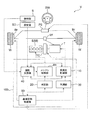
- FIG. 1 is a block diagram illustrating a schematic configuration of a vehicle control device according to an embodiment of the present disclosure.
- FIG. 2 is a block diagram illustrating an example of a configuration of a driving support unit of the vehicle control device illustrated in FIG. 1.
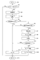
- FIG. 2 is a flowchart showing an example of the operation of the vehicle control device shown in FIG. 1.
- 2 is a time chart showing a state of a vehicle equipped with the vehicle control device shown in FIG. 1.
- FIG. 1 is a block diagram illustrating a schematic configuration of a vehicle control device 100 according to an embodiment of the present disclosure.
- the vehicle control device 100 is a device mounted on the vehicle V and has the following main features.
- the vehicle control device 100 includes a speed ratio control unit 10 that controls the speed ratio R t (see FIG. 4) of the vehicle V, and a determination unit 20 that determines whether the acceleration of the vehicle V is limited.
- Vehicle V includes, for example, engine E or motor M, torque converter TC, differential device Df, transmission unit T, tire W, brake Br, steering wheel SW, power steering device PS, and detection unit. S and a set value holding unit SD.
- the engine E or the motor M generates torque on the output shaft.
- the torque converter TC transmits the torque of the output shaft of the engine E or the motor M to the transmission unit T.
- the vehicle V may include a clutch including a friction engagement element instead of the torque converter TC.
- Shifting portion T is provided with a modified configuration capable gear ratio R t of the vehicle V.
- the speed ratio Rt of the vehicle V is a ratio of the number of revolutions on the input side of the engine E or the motor M, which is a power generation unit of the vehicle V, to the number of revolutions on the output side that rotates the tire W. . That is, when the rotation speed of the output side is constant, an increase in the speed ratio R t of the vehicle V denotes a shift to Lo side rotational speed of the input side is increased, a decrease in speed ratio R t of the vehicle V Means a shift to the Hi side where the number of revolutions on the input side decreases.
- Shifting portion T is the rotation of the transmitted engine E or the motor M via a torque converter TC, decelerating or accelerating in response to the speed change ratio R t, for transmission to the differential Df.
- the transmission unit T is, for example, a stepped transmission having gears.
- the stepped transmission is, for example, an automatic transmission (AT) that can select an arbitrary speed from among stepped speeds formed by frictional engagement elements such as a planetary gear mechanism, a clutch, and a brake. is there. That is, the gear ratio control unit 10 of the vehicle control device 100, for example, can be configured to via the transmission portion T is AT, controls the speed ratio R t of the vehicle V.
- AT automatic transmission
- the transmission unit T is, for example, a continuously variable transmission having a belt.
- the continuously variable transmission is, for example, a belt-pulley type continuously variable transmission (CVT: Continuously Variable Transmission) configured by friction engagement elements such as a planetary gear mechanism, a clutch, and a brake.
- CVT Continuously Variable Transmission
- an arbitrary speed ratio Rt can be selected from an innumerable speed ratio created by a pulley ratio between an input shaft pulley and an output shaft pulley, and the speed change mechanism is controlled by a hydraulic mechanism or an electric actuator mechanism.
- the gear ratio control unit 10 of the vehicle control device 100 may, for example, through the transmission portion T is CVT configured to control the gear ratio R t of the vehicle V.
- the transmission unit T may be a motor.
- the transmission unit T can be configured to change the torque or the number of revolutions of the engine E or the motor M, which is the power source, and transmit the changed torque to the tire W. That is, the gear ratio control unit 10 of the vehicle control device 100, for example, via the transmission portion T is a motor, can be configured to control the speed ratio R t of the vehicle V.
- the differential device Df is configured to transmit the torque transmitted from the transmission unit T to the tire W.
- the power steering device PS includes, for example, a motor and a gear, assists the driver of the vehicle V in operating the steering wheel SW, or automatically controls the steering of the vehicle V under the control of the vehicle behavior control unit 50. Is configured to do so.
- the detection unit S is a device for detecting, for example, the environment around the vehicle V and information on the vehicle V and other vehicles.
- the environment around the vehicle V includes, for example, other vehicles around the vehicle V, pedestrians, obstacles, road shapes, white lines, and other objects that affect the traveling of the vehicle V and information thereof.
- information on the vehicle V and other vehicles includes, for example, a lane in which the vehicle V and the other vehicles are traveling, a speed and a steering angle of the vehicle V, an inter-vehicle distance between the vehicle V and the other vehicles, and It includes the direction, position, speed, and traveling direction of other vehicles.
- the detection unit S includes, for example, a stereo camera, a monocular camera, a radar, a LIDAR, a navigation system and a communication device, a vehicle speed sensor, a steering angle sensor, an accelerator opening sensor, a brake depression force sensor, and a sensor for detecting operation of a turn signal. Includes various sensors.
- the set value holding unit SD includes a set speed v set and a set distance d set , which are set values of the speed and the inter-vehicle distance set by the driver of the vehicle V, the presence or absence of ACC (Adaptive Cruise Control), the total length L of the vehicle V, and Information about the total length L fv of other vehicles is stored.
- the set value holding unit SD provides the stored information to the driving support unit 40.
- the setting value holding unit SD includes, for example, an input device for inputting setting values, a storage device for storing the input setting values, and a control device for controlling these.
- the vehicle control device 100 of the present embodiment includes, for example, a gear ratio control unit 10, a determination unit 20, a prediction unit 30, a driving support unit 40, a vehicle behavior control unit 50, and an engine control unit 60.
- Each unit of the vehicle control device 100 can be configured as, for example, a part of an electronic control unit (ECU) of the vehicle V.
- ECU electronice control unit
- Gear ratio control unit 10 controls the speed ratio R t of the vehicle V. More specifically, for example, the speed of the vehicle V v, speed N e of the engine E, and based on the virtual accelerator pedal speed ratio map corresponding to the opening, the driving support unit 40 has a target speed ratio R t t decide. Gear ratio control unit 10, for example, based on the determined by the driving support unit 40 the target speed ratio R t t, controls the speed ratio R t of the vehicle V via the transmission portion T.
- Gear ratio control unit 10 for example, when it is determined that the acceleration limit by the determining unit 20 is configured to limit an increase in the speed ratio R t of the vehicle V. Further, the gear ratio control unit 10, for example, acceleration of the vehicle V is predicted by the prediction unit 30, and when it is determined that no acceleration limited by the determination unit 20, so as to increase the gear ratio R t of the vehicle V It is configured.
- the determination unit 20 is configured to determine whether or not the acceleration of the vehicle V is limited.
- whether or not the acceleration of the vehicle V is limited means whether or not there is a condition for limiting the acceleration of the vehicle V.
- the determination unit 20 obtains information on other vehicles around the vehicle V, for example, by the detection unit S of the vehicle V, and determines whether or not the acceleration of the vehicle V is restricted.
- the information that the determination unit 20 acquires by the detection unit S includes, for example, information on a lane in which another vehicle is traveling, and information on the speed, inter-vehicle distance, and traveling direction of the other vehicle.
- the determination unit 20 determines that, for example, the inter-vehicle distance d fv between the following vehicle running behind the vehicle V and the vehicle V is equal to or less than a preset distance. In such a case, it may be configured to determine that the acceleration is limited. In this case, the acceleration of the vehicle V and the change of the lane to the overtaking lane are restricted until the following vehicle passes the vehicle V or the inter-vehicle distance dfv between the following vehicle and the vehicle V is longer than the set distance. This is because it is necessary to avoid an abnormal approach between the vehicle and the vehicle V and a danger of collision.
- the determination unit 20 determines, for example, the inter-vehicle distance d fv between the vehicle V and the following vehicle traveling in the second lane adjacent to the first lane behind the vehicle V traveling in the first lane.
- the distance is equal to or less than a preset distance, it may be configured to determine that the acceleration is limited.
- the first lane is, for example, a traveling lane
- the second lane is, for example, an overtaking lane.
- the determination unit 20 determines that there is acceleration limitation when the relative speed between the following vehicle traveling behind the vehicle V and the vehicle V is equal to or higher than a preset speed. The determination may be made. Also in this case, the acceleration of the vehicle V and the lane change to the overtaking lane are restricted until the following vehicle overtakes the vehicle V or the relative speed between the following vehicle and the vehicle V becomes lower than the set speed. This is because it is necessary to avoid an abnormal approach between the vehicle and the vehicle V and a danger of collision.
- the determination unit 20 determines that the relative speed between the following vehicle traveling in the second lane behind the vehicle V traveling in the first lane and the vehicle V is equal to or higher than a preset speed. , It can be determined that acceleration is limited.
- the first lane is, for example, a traveling lane
- the second lane is, for example, an overtaking lane.
- the determination unit 20 may be configured to switch the determination with the acceleration limitation to the determination without the acceleration limitation based on the time until the following vehicle passes the vehicle V. Further, in the vehicle control device 100, the determination unit 20 may be configured to switch the determination with the acceleration limitation to the determination without the acceleration limitation after the time when the following vehicle passes the vehicle V.
- the prediction unit 30 is configured to predict the acceleration of the vehicle V.
- the prediction unit 30 obtains, for example, information on other vehicles around the vehicle V and information on the vehicle V by the detection unit S of the vehicle V, and predicts acceleration of the vehicle V.
- the information that the prediction unit 30 acquires by the detection unit S includes, for example, information on the operation of the turn signal of the vehicle V, information on the lane in which the vehicle V is traveling, the speed of the preceding vehicle traveling ahead of the vehicle V, and the preceding vehicle.
- the information includes information such as an inter-vehicle distance d lv between the vehicle V and the vehicle V, a set speed v set and a set distance d set previously set by the driver of the vehicle V.
- the prediction unit 30 can be configured to predict the acceleration of the vehicle V when predicting the lane change of the vehicle V. More specifically, for example, based on information acquired from the detection unit S, the prediction unit 30 determines that the vehicle V is traveling in the first lane, that a second lane adjacent to the first lane exists, The lane change of the vehicle V is predicted by recognizing that the turn signal of the vehicle V has been operated.
- the first lane is, for example, a traveling lane
- the second lane is, for example, an overtaking lane.
- the first lane is the lane on which the vehicle V is traveling
- the second lane is the opposite lane adjacent to the first lane. .
- the prediction unit 30 determines that the vehicle V It may be configured to predict the lane change of the vehicle. More specifically, the prediction unit 30 determines that the vehicle V and the preceding vehicle are traveling in the same first lane, based on the information acquired from the detection unit S, for example, and the second lane adjacent to the first lane. Exists, and the inter-vehicle distance d lv between the preceding vehicle and the vehicle V is recognized.
- the prediction unit 30 acquires the set distance d set of the inter-vehicle distance set by the driver of the vehicle V in advance and stored in the set value storage unit SD from the set value storage unit SD. Then, the prediction unit 30 compares the inter-vehicle distance d lv between the preceding vehicle and the vehicle V obtained by detecting unit S, and a set distance d The set acquired from the setting value holding unit SD, the inter-vehicle distance d lv set distance When it becomes d set or less, the lane change of the vehicle V is predicted.
- the prediction unit 30 may be configured to predict a lane change when the speed v of the vehicle V becomes equal to or lower than a preset speed v set . More specifically, the prediction unit 30 acquires the speed of the vehicle V based on the information acquired from the detection unit S, for example. Further, the prediction unit 30 acquires the set speed v set of the vehicle V set in advance by the driver of the vehicle V and stored in the set value storage unit SD from the set value storage unit SD. Then, the prediction unit 30 compares the speed v of the vehicle V acquired by the detection unit S with the set speed v set acquired from the set value holding unit SD, and the speed v of the vehicle V becomes equal to or less than the set speed v set. In this case, acceleration of the vehicle V or lane change is predicted.
- FIG. 2 is a block diagram showing an example of the configuration of the driving support unit 40 shown in FIG.
- the driving support unit 40 includes, for example, a target speed calculating unit 41, a braking / driving force calculating unit 42, an overtaking time calculating unit 43, an acceleration gear ratio calculating unit 44, a target gear ratio calculating unit 45, and a lane change recognition. It has a unit 46 and a steering angle calculation unit 47, and is configured to perform ACC that causes the vehicle V to follow a preceding vehicle while maintaining a predetermined inter-vehicle distance.
- the set speed v set of the vehicle V set by the driver of the vehicle V and the set distance d set between the vehicle V and the preceding vehicle are input to the target speed calculation unit 41 from the set value holding unit SD.
- the target speed calculation unit 41 receives, for example, the speed v lv of the preceding vehicle traveling ahead of the vehicle V and the inter-vehicle distance d lv between the preceding vehicle and the vehicle V from the detection unit S.
- the target speed calculator 41 for example, the vehicle V from the lane change recognition unit 46 is a signal s 1 indicating whether or not the lane change is input.
- the target speed calculator 41 calculates a target speed vt of the vehicle V based on the input information and outputs the calculated target speed vt to the braking / driving force calculator 42.
- the lane change recognition unit 46 for example, from the detecting unit S, and the steering angle signal s ra indicating the steering angle of the vehicle V, the signal s 2 indicating the lane in which the vehicle V is traveling is input. Lane change recognition unit 46 based on the input information, the vehicle V is determined whether or not the lane change, and outputs a signal s 1 indicating the determination result to the target speed calculating unit 41.
- the target speed vt of the vehicle V is input from the target speed calculation unit 41 to the braking / driving force calculation unit 42, the speed v of the vehicle V is input from the detection unit S, and the speed change of the vehicle V is the ratio R t is inputted, the target speed ratio from a target transmission ratio calculating section 45 R t t is input.
- Driving force calculation unit 42 calculates the target engine torque T e t and the target braking torque T b t, and outputs the target engine torque T e t to the engine control unit 60, the target brake The torque T bt is output to the gear ratio control unit 10 and the vehicle behavior control unit 50.
- driving force calculation unit 42 for example, obtains the rotational speed and the speed v of the vehicle V of the engine E or the motor M from the detection unit S, may calculate the transmission ratio R t based on the information.
- the overtaking time calculation unit 43 for example, from the detecting unit S, the vehicle V and the signal s 3 including information on the lane following vehicle is traveling, vehicle distance d fv of the following vehicle with speed v fv and the vehicle V of the following vehicle a signal s 4 including the information, the signal s 5 including operation information of the turn signal is input. Also, the overtaking time calculation unit 43, the transmission gear ratio R t of the vehicle V from the speed change ratio control unit 10 is inputted, the accelerating speed ratio from the acceleration gear ratio calculation unit 44 R t a is input. The overtaking time calculation unit 43 calculates the overtaking time tp until the succeeding vehicle passes the vehicle V and the shift start timing ts based on the input information, and outputs them to the target gear ratio calculation unit 45.
- the overtaking time calculation unit 43 based on, for example, the input information, is located behind the vehicle V traveling in the first lane, and the following vehicle and the vehicle V traveling in the second lane. The relative speed and the relative distance between are calculated. Then, the overtaking time calculation unit 43 calculates the overtaking time tp and the shift start timing ts until the following vehicle overtakes the vehicle V based on the calculated relative speed and relative distance between the following vehicle and the vehicle V. Output to the ratio calculator 45.
- the acceleration speed ratio calculation unit 44 receives the set speed v set of the vehicle V set by the driver of the vehicle V from the set value holding unit SD, and receives the speed v of the vehicle V from the detection unit S, speed ratio R t from the gear ratio control unit 10 the vehicle V is input.
- the acceleration gear ratio calculator 44 calculates the acceleration gear ratio R ta for accelerating the vehicle V based on the input information, and outputs the acceleration gear ratio R ta to the overtaking time calculator 43 and the target gear ratio calculator 45. I do.
- the gear shift start timing ts is input from the overtaking time calculator 43, and the acceleration gear ratio R ta is input from the acceleration gear ratio calculator 44, and the target gear ratio is calculated based on these information.
- the gear ratio R tt is calculated and output to the gear ratio control unit 10.
- the target speed ratio calculating unit 45 only when it is necessary to pre-shift to the vehicle V accelerates, may constitute a target gear ratio R t t to output to the transmission ratio control unit 10.
- the steering angle calculating unit 47 for example, from the detecting unit S, and the steering angle signal s ra indicating the steering angle of the vehicle V, the signal s 2 indicating the lane in which the vehicle V is traveling is input.
- the steering angle calculation unit 47 calculates position information of the vehicle V for determining the left / right position with respect to the traveling direction of the vehicle V based on the input information, and controls the target steering angle for controlling the left / right position of the vehicle V.
- the signal s rat is calculated and output to the vehicle behavior control unit 50.
- the driving support unit 40 recognizes the lane in which the vehicle V is traveling as the first lane, for example, by the overtaking time calculation unit 43 or the lane change recognition unit 46, and sets the second lane for the vehicle V to pass the preceding vehicle.
- the presence or absence may be determined.
- the presence or absence of the second lane for the vehicle V to pass the preceding vehicle may be determined based on map information of a navigation system such as a global positioning satellite system (GNSS) constituting the detection unit S.
- GNSS global positioning satellite system
- the determination may be made based on an image of a camera constituting the detection unit S. That is, the method for determining the presence or absence of the second lane that can pass the preceding vehicle is not particularly limited.
- the vehicle behavior control unit 50 for example, from the driving support unit 40, the target braking torque T b t and the target steering angle signal s ra t is input. Vehicle behavior control unit 50 brakes the vehicle V by controlling the brake Br based on the target braking torque T b t, steer the vehicle V by controlling the power steering system PS on the basis of the target steering angle signal s ra t I do.
- the engine control unit 60 receives, for example, the target engine torque T et from the driving support unit 40.
- the engine control unit 60 for example, is configured to control the rotational speed N e and the torque T e of the engine E of the vehicle V based on the input target engine torque T e t.
- the engine control unit 60 for example, the determination unit 20, a determination of Yes acceleration limit, switching to the determination of no acceleration limit, the gear ratio control unit 10, until increase the gear ratio R t, the set rotational speed set in advance such that less may control the rotational speed N e of the engine E (see FIG. 4).
- FIG. 3 is a flowchart showing an example of the operation of the vehicle control device 100 shown in FIG.
- step S1 control by the vehicle control device 100 is started.
- step S2 the driving support unit 40 determines whether the vehicle V is running in the ACC mode. Specifically, for example, the driving support unit 40 acquires information on the presence or absence of the setting of ACC from the setting value holding unit SD, and proceeds to step S3 when the vehicle V is running in the ACC mode (Yes). . On the other hand, when the vehicle V is not running in the ACC mode (No), the process proceeds to step S13, and returns to step S1.
- step S3 the driving support unit 40 acquires, for example, the inter-vehicle distance d lv between the preceding vehicle and the vehicle V, the relative speed between the preceding vehicle and the vehicle V, and the speed v of the vehicle V from the detection unit S, and holds the set value.
- the set speed v set of the vehicle V is obtained from the unit SD.
- the driving support unit 40 for example, by lane change recognition unit 46 obtains the signal s 2 indicating the lane in which the steering angle signal s ra and the vehicle V from the detection unit S running, the vehicle V is changing lanes and outputs a signal s 1 which indicates whether the inside to the target speed calculator 41.
- step S4 the driving support unit 40, for example, by the target speed calculating unit 41 calculates the target speed vt of the vehicle V, the target engine torque T by driving force calculation unit 42 e t and the target braking torque T b Calculate t.
- the calculation of the target speed vt of the vehicle V can be performed, for example, as follows. If there is no preceding vehicle ahead of the vehicle V, the set speed v set set by the driver of the vehicle V is set as the target speed vt. If forward preceding vehicle of the vehicle V is present, the inter-vehicle distance d lv between the vehicle V and the preceding vehicle, and calculates the velocity v a of maintaining a set distance d The set that has been set by the driver of the vehicle V of the calculated velocity v a a set speed v the set, and the target speed vt slower ones.
- the set may, for example, can be performed as follows.
- the input information is, for example, a speed v of the vehicle V and a set distance d set set by a driver of the vehicle V.
- the set distance d set is, for example, three stages of a short distance, a medium distance, and a long distance.
- an experiment is performed in advance to create a map that outputs information on the distance between vehicles.
- the information of the inter-vehicle distance d a from the map is output.
- the output value of the feedback control is defined as the speed v a of the vehicle V for maintaining the inter-vehicle distance d lv between the vehicle V and the preceding vehicle at a set distance d set .
- the calculation of the target engine torque T et can be performed, for example, as follows. First, feedback control is performed in accordance with the deviation between the target speed vt of the vehicle V and the actual speed v, and the output value is used as the target driving force Ft. Then, based on the target driving force Ft, the speed ratio R t of the vehicle V, the gear ratio R d of the differential device Df, the radius r w of the tire W, and the running resistance fr of the vehicle V, the target engine is calculated by the following equation (1). Calculate the torque T et .
- the running resistance fr of the vehicle V can be estimated from the speed v of the vehicle V. Further, the above equation (1) is a simple calculation method of an example of a method for calculating the target engine torque T e t, it may calculate the target engine torque T e t by more detailed operations.
- the calculation of the target braking torque T bt can be performed, for example, as follows.
- the target speed vt of the vehicle V is reduced, to calculate a target braking torque T b t for decelerating the vehicle V.
- the target driving force Ft becomes a negative value, and its value as the target braking torque T b t.
- the target braking torque T bt can be a value that takes into account the braking force of the engine E due to the decrease in the target engine torque T et .
- step S5 the vehicle control device 100 determines, for example, whether or not the vehicle V has changed lanes and whether or not the target speed vt has increased by the driving support unit 40, for example.
- the lane change of the vehicle V may be performed by the driver of the vehicle V operating the steering wheel SW and the accelerator pedal, or may be automatically performed by the driving support unit 40.
- Whether or not the vehicle V has changed lanes is determined, for example, by the lane change recognizing unit 46 of the driving support unit 40, as described above, based on the steering angle signal sra indicating the steering angle of the vehicle V and the lane in which the vehicle V is traveling. it can be based on a signal s 2 indicative.
- step S5 for example, when the driving support unit 40 determines that the lane change of the vehicle V has been changed and that the target speed vt is increasing (Yes), the process proceeds to step S12.
- step S12 the target engine torque T e t and the target braking torque T b t calculated in step S4 is output to the engine control unit 60 and the vehicle behavior control unit 50, respectively, the process proceeds to step S13, the flow returns to step S1.
- step S5 for example, when the driving support unit 40 determines that the lane of the vehicle V has not been changed or that the target speed vt has not increased (No), the process proceeds to step S6. move on.
- step S6 it is determined whether acceleration of the vehicle V is predicted.
- the prediction unit 30, for example via the driving support unit 40, a signal s 3 including information on the lane on which the vehicle V and the following vehicle is traveling, distance to the following vehicle and the speed and the vehicle V of the following vehicle a signal s 4 containing information d fv, acquires the signal s 5 including operation information of the turn signal.
- the prediction unit 30 predicts a lane change of the vehicle V when the turn signal is operated and there is a lane that can pass the preceding vehicle, based on the acquired information, thereby predicting the acceleration of the vehicle V. I do.
- step S6 the prediction unit 30 determines whether the inter-vehicle distance d lv between the preceding vehicle traveling ahead of the vehicle V and the vehicle V is equal to or less than a preset distance d set, or the speed v of the vehicle V.
- the vehicle speed becomes equal to or less than the preset speed v set
- the lane change of the vehicle V may be predicted, and thereby the acceleration of the vehicle V may be predicted.
- step S6 when acceleration of the vehicle V is predicted by the prediction unit 30 (Yes), the process proceeds to step S7, and when acceleration of the vehicle V is not predicted by the prediction unit 30 (No), steps S12 and S13 are performed. Then, the process returns to step S1.
- step S7 the driving support unit 40 acquires information necessary for calculating the target gear ratio R tt .
- the speed v of the vehicle V, the set speed v set and the speed ratio Rt are acquired by the speed change ratio calculating unit 44 for acceleration, and the speed v fv of the following vehicle and the vehicle V are calculated by the overtaking time calculating unit 43.
- Information on the inter-vehicle distance d fv of the following vehicle is acquired, and the process proceeds to step S8.
- step S8 the target speed ratio R t t the shift time t Shift is calculated on the basis of the information acquired in step S7. Specifically, the speed change ratio for acceleration R ta is calculated by the speed change ratio calculation unit for acceleration 44, and the shift start timing ts is calculated by the overtaking time calculation unit 43. In addition, these accelerating speed ratio R t a and the transmission start timing ts is inputted to the target transmission ratio calculating section 45, a target speed ratio R t t the shift time t Shift is calculated by the target speed ratio calculating unit 45.
- the calculation of the target speed ratio R tt and the shift time t shift can be performed, for example, as follows. First, a target acceleration at of the vehicle V is calculated from the speed v and the set speed v set of the vehicle V. Then, to calculate a target gear ratio R t t from the target acceleration at and velocity v of the vehicle V. Further, a shift time t shift is calculated from the target speed ratio R tt of the vehicle V and the current speed ratio R t .
- the target acceleration at for example, an acceleration map corresponding to the input of the speed v of the vehicle V and the set speed v set is created based on an experiment in advance, and the acceleration map, the speed v of the vehicle V, and It can be derived based on the set speed v set .
- the target speed ratio R tt is calculated, for example, by preparing a speed ratio map corresponding to the speed v of the vehicle V and the target acceleration at on the basis of an experiment in advance, and calculating the speed ratio map, the speed v of the vehicle V, and the target acceleration. can be derived based on at.
- the shift time t shift can be calculated as follows. First, a threshold value t th of the shift time t shift based on the current speed ratio R t and the target speed ratio R t t of the vehicle V is determined. This threshold value t th is a limit value of the shift speed. Then, based on the threshold value t th and the current speed ratio R t and target speed ratio R t t of the vehicle V, a shift time t shift is calculated based on the following equation (2).
- the driving support unit 40 uses the overtaking time calculation unit 43, for example, to detect the speed v of the vehicle V, the speed v fv of the following vehicle, the following vehicle and the vehicle from the detection unit S and the set value holding unit SD.
- the inter-vehicle distance d fv to the vehicle V, the total length L of the vehicle V, and the total length L fv of the following vehicle are acquired.
- the total length L fv of the following vehicle is determined, for example, by referring to the numerical value of the total length table for each type of vehicle stored in the set value holding unit SD based on the detection of the type of the following vehicle by the detection unit S. For example, a constant value stored in the value holding unit SD can be used.
- the overtaking time calculation unit 43 calculates an overtaking time tp until the succeeding vehicle overtakes the vehicle V based on the acquired information and based on the following equation (3), for example.
- step S10 the determination unit 20 determines whether the acceleration of the vehicle V is limited. If the determination unit 20 determines that the acceleration is limited (Yes), the speed ratio control unit 10 limits the increase in the speed ratio Rt of the vehicle V, and proceeds to step S12. In step S12, the target engine torque T e t and the target braking torque T b t calculated in step S4 is output to the engine control unit 60 and the vehicle behavior control unit 50, respectively, through step S13, the flow returns to step S1.
- FIG. 4 is a time chart showing a state of vehicle V on which vehicle control device 100 shown in FIG. 1 is mounted.
- the horizontal axes of a plurality of graphs arranged from top to bottom are all time.
- the lane change of the vehicle V and the shift timing of the vehicle V.
- Each graph shown in FIG. 4 is described by dividing the time shown on the horizontal axis into several sections. Specifically, the period in which the vehicle V is traveling at normal ACC mode and running state A, the period during which the turn signal is being turned on and running in ACC mode and running state B, the gear ratio R t A period in which the control is performed is referred to as a traveling state C, and a period in which the acceleration is performed is referred to as a traveling state D.
- the speed v of the vehicle V is indicated by a solid line
- the speed v lv of the preceding vehicle is indicated by a broken line
- the speed v fv of the following vehicle is indicated by a dashed line.
- the third inter-vehicle distance graph from the bottom in FIG. 4 the inter-vehicle distance d lv between the preceding vehicle and the vehicle V is displayed by a broken line
- the inter-vehicle distance d fv between the following vehicle and the vehicle V is displayed by a dashed line.
- the preceding vehicle travels in front of the vehicle V at a speed v lv lower than the set speed v set of the vehicle V, and moves behind the vehicle V at a speed higher than the set speed v set of the vehicle V.
- the following vehicle is running at v fv .
- the control by the vehicle control device 100 is started in step S1 shown in FIG. 3, and it is determined in step S2 that the vehicle is traveling in the ACC mode (Yes).
- step S3 the detection unit S and the setting are set.
- Various types of information are acquired from the value holding unit SD.
- step S4 the traveling state A, the target engine torque T e t and the target braking torque T b t is calculated in step S4, it is not the lane change of the vehicle V (No) is determined in step S5. Further, since the turn signal is not operated from the beginning to the end of the running state A, the acceleration of the vehicle V is not predicted in step S6 (No), and the process proceeds to step S12.
- the target engine torque T e t and the target braking torque T b t calculated in step S4 is output, the brake Br is controlled by the vehicle behavior control unit 50, the engine E is controlled by the engine control unit 60, transmission The transmission unit T is controlled by the ratio control unit 10.
- Step S1 to Step S6, Step S12, and Step S13 are repeated at a predetermined cycle.
- the vehicle control device 100 controls the speed v of the vehicle V such that the inter-vehicle distance d lv between the preceding vehicle and the vehicle V converges on the set distance d set which is a preset inter-vehicle distance. I have.
- the speed v of the vehicle V gradually decreases as the inter-vehicle distance d lv between the preceding vehicle and the vehicle V shown in the inter-vehicle distance graph of FIG.
- the gear ratio R t of the vehicle V like speed N e and the torque T e of the engine E is constant, and increases with the decrease in the velocity v of the vehicle V.
- the speed v of the vehicle V further decreases and becomes equal to the speed v lv of the preceding vehicle, and the vehicle V is set.
- the vehicle follows the preceding vehicle while maintaining the distance d set .
- the speed ratio Rt of the vehicle V increases when the vehicle V decelerates, and becomes constant when the vehicle V shifts to constant speed traveling.
- the torque T e of the engine E is reduced with an increase in deceleration speed ratio R t of the vehicle V.
- the turn signal is turned on, and the vehicle shifts to the traveling state B.
- step S6 the turn signal is operated to be turned ON, and since the lane that can pass the preceding vehicle is recognized, acceleration of the vehicle V is predicted in step S6 (Yes), and the process proceeds to step S7. Then, step S7 information necessary for calculation of the target speed ratio R t t are acquired, the target gear ratio R t t the shift time t Shift is calculated in step S8, the time tp passing in step S9 are calculated. Then, in step S10, the determination unit 20 determines whether or not the acceleration of the vehicle V is limited.
- step S10 the determination unit 20 determines that the inter-vehicle distance d fv between the following vehicle running behind the vehicle V and the vehicle V is less than or equal to a preset distance, It is determined that there is.
- the determination unit 20 has an acceleration limitation; Is determined.
- the determination unit 20 may determine whether or not there is an acceleration restriction as follows. First, the shift start timing ts is calculated from the overtaking time tp and the shift time t shift by the following equation (4), and it is determined whether or not the following inequality equation (5) is satisfied.
- the lower limit threshold value ts low of the shift start timing ts is a constant for determining, for example, a case where the following vehicle is overtaking the vehicle V or a case where there is no following vehicle. This is the threshold.
- the upper threshold value ts high of the shift start timing ts is set when the inter-vehicle distance d fv between the vehicle V and the following vehicle is sufficiently long, or the relative speed (v fv -v) between the vehicle V and the following vehicle. Is a constant threshold value for determining when it takes time for the following vehicle to pass the vehicle V, such as when the speed is sufficiently low.
- the threshold ts low and the threshold ts high can be determined to be appropriate values based on, for example, experiments.
- step S10 when the shift start timing ts satisfies the above inequality (5), the determination unit 20 determines that acceleration is limited (Yes), proceeds to step S12, and returns to step S1 via step S13. . On the other hand, when the shift start timing ts does not satisfy the above inequality (5) in step S10, the determination unit 20 determines that there is no acceleration limitation (No), and proceeds to step S11.
- step S10 determines in step S10 that the acceleration is limited (Yes), and proceeds to step S12.
- step S12 the target engine torque T e t and the target braking torque T b t calculated in step S4 is output to the engine control unit 60 and the vehicle behavior control unit 50, respectively, the process proceeds to step S13, the flow returns to step S1. From the beginning to the end of the running state B, Step S1 to Step S10, Step S12, and Step S13 are repeated at a predetermined cycle.
- the vehicle control device 100 can determine the acceleration limit of the vehicle V by the determination unit 20, for example, the acceleration limit due to the presence of a following vehicle that is trying to pass the vehicle V.
- the acceleration limit it is possible to limit the increase in the speed ratio R t by the shift ratio control unit 10. Accordingly, the acceleration up to the limit is eliminated, the speed ratio it is possible to suppress an increase of R t, speed N e of the engine E is prevented from being uselessly increased, to improve the quietness and the fuel economy of the vehicle V it can.
- the vehicle V follows the preceding vehicle at a constant speed while maintaining the inter-vehicle distance d lv with the preceding vehicle at the set distance d set .
- the inter-vehicle distance d fv between the following vehicle and the vehicle V becomes zero or approaches zero, in step S10 shown in FIG. 3, for example, as described above, the inter-vehicle distance d fv between the following vehicle and the vehicle V.
- the determination unit 20 determines that there is no acceleration limit (No) based on the overtaking time tp until the vehicle overtakes the vehicle V or the above inequality (5), and proceeds to step S11.
- step S11 it updates the target speed ratio R t t and the target engine torque T e t calculated in step S8, the process proceeds to step S14.
- Target engine torque T e t updated in step S11 a target engine torque T e t a shift instruction caused by target gear ratio R t t was also considered. Specifically, when the target gear ratio R tt is indicated, the gear ratio R t until the next control cycle is predicted, and the target engine calculated by the above equation (1) using the predicted gear ratio R t. This is the torque T et .
- step S14 the target gear ratio is updated at step S11 R t t, the target engine torque T e t, and the target braking torque T b t, and outputs the driving support unit 40.
- the target speed ratio R t t output from the driving support unit 40 is input to, for example, the speed ratio control unit 10, and the speed ratio R t of the vehicle V is increased via the speed change unit T.
- the speed ratio R t of the vehicle V starts increasing.
- the engine E because they are controlled by the engine control unit 60 based on the target engine torque T e t updated in step S11, the torque T e of the amount corresponding to the gear ratio R t is increased engine is reduced ing.
- the vehicle V still follows the preceding vehicle traveling at a speed v lv lower than the set speed v set of the vehicle V while maintaining the set distance d set . Thereafter, when the succeeding vehicle completely overtakes the vehicle V and the vehicle V changes lanes and starts overtaking the preceding vehicle, the target speed vt of the vehicle V calculated by the target speed calculation unit 41 of the driving support unit 40 increases. . At this time, since the speed ratio R t is already shifted to the target gear ratio R t t, it is possible to secure a high responsiveness to acceleration of the vehicle V.
- the lane change of the vehicle V may be performed by the driver of the vehicle V operating the steering wheel SW and the accelerator pedal, and the driving support unit 40 performs the power steering via the vehicle behavior control unit 50 and the engine control unit 60. This may be performed by controlling the device PS and the engine E.
- the vehicle control device 100 is a device mounted on a vehicle V, and the gear ratio control unit 10 for controlling the gear ratio R t of the vehicle V, the acceleration of the vehicle V A determination unit 20 for determining whether there is a restriction.
- the determination unit 20 determines that there is an acceleration limitation, and the gear ratio control unit 10 changes the speed.
- the increase in the ratio Rt can be limited.
- the gear ratio control unit 10 can immediately increase the gear ratio Rt . Therefore, according to the vehicle control device 100 of the present embodiment, while maintaining a high responsiveness to acceleration of the vehicle V, to prevent an increase in rotational speed N e unnecessary engine E, the quietness of the vehicle V and Fuel efficiency can be improved.
- the vehicle control device 100 of the present embodiment includes the prediction unit 30 that predicts the acceleration of the vehicle V as described above. Then, the gear ratio control unit 10, the acceleration of the vehicle V is predicted by the prediction unit 30, and, when it is determined that no acceleration limited by the determination unit 20, configured to increase the speed ratio R t of the vehicle V Have been.
- the prediction unit 30 is configured to predict acceleration of the vehicle V when predicting a lane change of the vehicle V, for example.
- the prediction unit 30 determines that, for example, the inter-vehicle distance d lv between the preceding vehicle traveling ahead of the vehicle V and the vehicle V is equal to or less than a preset set distance d set. In such a case, a change in the lane of the vehicle V is predicted.
- the vehicle V catches up with a preceding vehicle traveling ahead of the vehicle V at a lower speed than the vehicle V, and the inter-vehicle distance d lv between the preceding vehicle and the vehicle V is equal to or less than a preset distance d set.
- the lane change and acceleration of the vehicle V can be quickly predicted by the prediction unit 30 of the vehicle control device 100. As a result, it is possible to more accurately predict the acceleration of the vehicle V, secure high responsiveness to the acceleration of the vehicle V, and quickly and smoothly overtake the preceding vehicle.
- the prediction unit 30 is configured to predict a lane change, for example, when the speed v of the vehicle V becomes equal to or lower than a preset speed v set .
- the prediction unit 30 can predict the lane change and acceleration of the vehicle V, that is, the passing of the preceding vehicle. Thereby, the acceleration of the vehicle V can be more accurately and quickly predicted.
- the prediction unit 30 sets the vehicle V Lane change and acceleration, that is, passing of a preceding vehicle can be predicted. Thereby, the acceleration of the vehicle V can be more accurately and quickly predicted. Accordingly, the preceding vehicle not only makes it possible to overtake quickly and smoothly, to prevent an increase in rotational speed N e unnecessary engine E, can be to improve the quietness and the fuel economy of the vehicle V.
- the vehicle control device 100 of the present embodiment includes the driving support unit 40 that causes the vehicle V to follow the preceding vehicle.
- the driving support unit 40 is configured to change the lane of the vehicle V when the determination unit 20 determines that there is no acceleration restriction and the prediction unit 30 predicts a lane change.
- the prediction unit 30 predicts acceleration when the vehicle V traveling in the ACC mode follows a preceding vehicle traveling ahead of the vehicle V at a lower speed than the vehicle V, the acceleration is not increased. If there is a restriction, the lane is not changed by the driving support unit 40, and the speed ratio Rt does not increase. Therefore, increase in the rotational speed N e unnecessary engine E is prevented, it can be to improve the quietness and the fuel economy of the vehicle V. Thereafter, when the acceleration limit is removed, the speed ratio control unit 10 increases the speed ratio Rt , and the driving support unit 40 changes and accelerates the vehicle V running in the ACC mode so that the preceding vehicle is quickly and smoothly. You can overtake.
- the determination unit 20 determines, for example, when the inter-vehicle distance d fv between the following vehicle traveling behind the vehicle V and the vehicle V is equal to or less than a preset distance. Is configured to determine that there is an acceleration limit.
- the determination unit 20 determines, for example, when the relative speed between the following vehicle traveling behind the vehicle V and the vehicle V is equal to or higher than a preset speed. Is configured to determine that there is an acceleration limit.
- the determination unit 20 switches the determination of the presence of the acceleration limitation to the determination of the absence of the acceleration limitation based on, for example, the overtaking time tp until the following vehicle overtakes the vehicle V. It is configured as follows.
- the speed ratio control unit 10 can increase the speed ratio Rt . Accordingly, in a state in which acceleration is limited to prevent an increase in rotational speed N e unnecessary engine E, not only can be improved quietness and fuel economy of the vehicle V, the following vehicle completes overtaking vehicle V By this time, the increase in the speed ratio Rt is completed, and high responsiveness to acceleration of the vehicle V can be secured.
- the determination unit 20 is configured to switch the determination with the acceleration limitation to the determination without the acceleration limitation, for example, after the time when the following vehicle overtakes the vehicle V. Is also good.
- the gear ratio control unit 10 controls the gear ratio by the gear ratio control unit 10 until the vehicle V catches up with the preceding vehicle traveling ahead of the vehicle V at a lower speed than the vehicle V and the following vehicle completes the overtaking of the vehicle V.
- the increase in R t is limited. Therefore, an increase in the rotational speed N e unnecessary engine E in a state where acceleration is restricted more effectively prevented, it can be further improved quietness and fuel economy of the vehicle V.
- the vehicle control device 100 of the present embodiment includes an engine control unit 60 that controls the rotation speed of the engine E of the vehicle V. Then, the engine control unit 60, for example, switching a determination decision unit 20 is located acceleration limit to the determination of no acceleration limit until the gear ratio control unit 10 increases the speed ratio R t, advance the rotational speed of the engine E It is configured to control so as to be equal to or less than the set rotational speed.
- This configuration an increase in the rotational speed N e unnecessary engine E in a state where acceleration is restricted more effectively prevented, can be further improved quietness and fuel economy of the vehicle V.
- a vehicle V to which the vehicle control device 100 is mounted is provided with a transmission portion T that can change the speed ratio R t of the vehicle V.
- the gear ratio control unit 10 of the vehicle control device 100 is configured to control the gear ratio R t of the vehicle V via the transmission portion T.
- the transmission unit T is, for example, a stepped transmission having a gear, a continuously variable transmission having a belt, or a motor. With this configuration, the vehicle control device 100 controls the transmission portion T by the gear ratio control unit 10 can control the speed ratio R t of the vehicle V.
- the vehicle control device 100 capable of improving quietness and fuel efficiency while maintaining high responsiveness to acceleration of the vehicle V. .
Landscapes
- Engineering & Computer Science (AREA)
- Mechanical Engineering (AREA)
- Transportation (AREA)
- General Engineering & Computer Science (AREA)
- Chemical & Material Sciences (AREA)
- Combustion & Propulsion (AREA)
- Automation & Control Theory (AREA)
- Power Engineering (AREA)
- Control Of Driving Devices And Active Controlling Of Vehicle (AREA)
- Control Of Transmission Device (AREA)
- Electric Propulsion And Braking For Vehicles (AREA)
- Hybrid Electric Vehicles (AREA)
Abstract
L'invention concerne un dispositif de commande de véhicule qui est susceptible d'améliorer le caractère silencieux et l'efficacité du carburant, tout en maintenant une réactivité élevée à l'accélération du véhicule. Le dispositif de commande de véhicule (100) selon l'invention comprend : une unité de commande de rapport de vitesse (10) qui commande le rapport de vitesse du véhicule (V); et une unité de détermination (20) qui détermine si oui ou non le véhicule (V) a une accélération limitée. L'unité de commande de rapport de vitesse (10) est conçue de façon à limiter une augmentation du rapport de vitesse (Rt) si l'unité de détermination (20) a déterminé que l'accélération est limitée.
Priority Applications (2)
| Application Number | Priority Date | Filing Date | Title |
|---|---|---|---|
| JP2020528778A JP6989704B2 (ja) | 2018-07-06 | 2019-06-19 | 車両用制御装置 |
| US17/055,490 US12036993B2 (en) | 2018-07-06 | 2019-06-19 | Control device for vehicles |
Applications Claiming Priority (2)
| Application Number | Priority Date | Filing Date | Title |
|---|---|---|---|
| JP2018-129485 | 2018-07-06 | ||
| JP2018129485 | 2018-07-06 |
Publications (1)
| Publication Number | Publication Date |
|---|---|
| WO2020008873A1 true WO2020008873A1 (fr) | 2020-01-09 |
Family
ID=69060094
Family Applications (1)
| Application Number | Title | Priority Date | Filing Date |
|---|---|---|---|
| PCT/JP2019/024209 Ceased WO2020008873A1 (fr) | 2018-07-06 | 2019-06-19 | Dispositif de commande pour véhicules |
Country Status (3)
| Country | Link |
|---|---|
| US (1) | US12036993B2 (fr) |
| JP (1) | JP6989704B2 (fr) |
| WO (1) | WO2020008873A1 (fr) |
Cited By (4)
| Publication number | Priority date | Publication date | Assignee | Title |
|---|---|---|---|---|
| JP2021160537A (ja) * | 2020-03-31 | 2021-10-11 | 本田技研工業株式会社 | 自動変速機を搭載した車両の制御装置および制御方法 |
| JP2023084510A (ja) * | 2021-12-07 | 2023-06-19 | トヨタ自動車株式会社 | 変速制御装置、変速制御方法及び変速制御用コンピュータプログラム |
| JP2023097127A (ja) * | 2021-12-27 | 2023-07-07 | 株式会社Subaru | 車両の運転支援装置 |
| JP2023138401A (ja) * | 2022-03-16 | 2023-10-02 | コンチネンタル・オートナマス・モビリティ・ジャーマニー・ゲゼルシャフト・ミト・ベシュレンクテル・ハフツング | 自車両用支援システムおよび方法 |
Families Citing this family (4)
| Publication number | Priority date | Publication date | Assignee | Title |
|---|---|---|---|---|
| DE102019101662A1 (de) * | 2019-01-23 | 2020-07-23 | Bayerische Motoren Werke Aktiengesellschaft | Verfahren und Steuereinheit zum Betrieb eines adaptiven Geschwindigkeitsreglers |
| KR20210150921A (ko) * | 2020-06-04 | 2021-12-13 | 현대모비스 주식회사 | 차량의 안전 주행 제어 시스템 및 방법 |
| US12187314B2 (en) | 2021-12-01 | 2025-01-07 | Waymo Llc | Operational response model based on operational parameters |
| JP7824577B2 (ja) | 2023-02-03 | 2026-03-05 | トヨタ自動車株式会社 | 車両の制御装置 |
Citations (5)
| Publication number | Priority date | Publication date | Assignee | Title |
|---|---|---|---|---|
| JPS61262259A (ja) * | 1985-05-11 | 1986-11-20 | Toyota Motor Corp | 自動変速機の制御装置 |
| JP2001271922A (ja) * | 2000-03-27 | 2001-10-05 | Suzuki Motor Corp | 自動変速機の変速制御装置 |
| JP2008110695A (ja) * | 2006-10-31 | 2008-05-15 | Toyota Motor Corp | 車両の速度制限装置 |
| JP2017024479A (ja) * | 2015-07-17 | 2017-02-02 | トヨタ自動車株式会社 | クルーズコントロール装置 |
| JP2018005827A (ja) * | 2016-07-08 | 2018-01-11 | 株式会社デンソーテン | 車線変更支援装置および車線変更支援方法 |
Family Cites Families (3)
| Publication number | Priority date | Publication date | Assignee | Title |
|---|---|---|---|---|
| US4788892A (en) | 1985-05-11 | 1988-12-06 | Toyota Jidosha Kabushiki Kaisha | Controller for automatic transmission |
| JP3627613B2 (ja) | 2000-02-22 | 2005-03-09 | 日産自動車株式会社 | 自動車の駆動力制御装置 |
| WO2011074062A1 (fr) * | 2009-12-15 | 2011-06-23 | 日産自動車株式会社 | Dispositif et procédé permettant de commander une transmission à variation continue à courroie pour un véhicule |
-
2019
- 2019-06-19 WO PCT/JP2019/024209 patent/WO2020008873A1/fr not_active Ceased
- 2019-06-19 US US17/055,490 patent/US12036993B2/en active Active
- 2019-06-19 JP JP2020528778A patent/JP6989704B2/ja active Active
Patent Citations (5)
| Publication number | Priority date | Publication date | Assignee | Title |
|---|---|---|---|---|
| JPS61262259A (ja) * | 1985-05-11 | 1986-11-20 | Toyota Motor Corp | 自動変速機の制御装置 |
| JP2001271922A (ja) * | 2000-03-27 | 2001-10-05 | Suzuki Motor Corp | 自動変速機の変速制御装置 |
| JP2008110695A (ja) * | 2006-10-31 | 2008-05-15 | Toyota Motor Corp | 車両の速度制限装置 |
| JP2017024479A (ja) * | 2015-07-17 | 2017-02-02 | トヨタ自動車株式会社 | クルーズコントロール装置 |
| JP2018005827A (ja) * | 2016-07-08 | 2018-01-11 | 株式会社デンソーテン | 車線変更支援装置および車線変更支援方法 |
Cited By (10)
| Publication number | Priority date | Publication date | Assignee | Title |
|---|---|---|---|---|
| JP2021160537A (ja) * | 2020-03-31 | 2021-10-11 | 本田技研工業株式会社 | 自動変速機を搭載した車両の制御装置および制御方法 |
| CN113525376A (zh) * | 2020-03-31 | 2021-10-22 | 本田技研工业株式会社 | 车辆的控制装置、车辆的控制方法及存储介质 |
| JP7506994B2 (ja) | 2020-03-31 | 2024-06-27 | 本田技研工業株式会社 | 自動変速機を搭載した車両の制御装置および制御方法 |
| CN113525376B (zh) * | 2020-03-31 | 2024-07-30 | 本田技研工业株式会社 | 车辆的控制装置、车辆的控制方法及计算机可读存储介质 |
| JP2023084510A (ja) * | 2021-12-07 | 2023-06-19 | トヨタ自動車株式会社 | 変速制御装置、変速制御方法及び変速制御用コンピュータプログラム |
| JP7464035B2 (ja) | 2021-12-07 | 2024-04-09 | トヨタ自動車株式会社 | 変速制御装置、変速制御方法及び変速制御用コンピュータプログラム |
| US12162469B2 (en) | 2021-12-07 | 2024-12-10 | Toyota Jidosha Kabushiki Kaisha | Controller, method, and computer program for controlling transmission |
| JP2023097127A (ja) * | 2021-12-27 | 2023-07-07 | 株式会社Subaru | 車両の運転支援装置 |
| JP7804459B2 (ja) | 2021-12-27 | 2026-01-22 | 株式会社Subaru | 車両の運転支援装置 |
| JP2023138401A (ja) * | 2022-03-16 | 2023-10-02 | コンチネンタル・オートナマス・モビリティ・ジャーマニー・ゲゼルシャフト・ミト・ベシュレンクテル・ハフツング | 自車両用支援システムおよび方法 |
Also Published As
| Publication number | Publication date |
|---|---|
| JP6989704B2 (ja) | 2022-01-05 |
| US12036993B2 (en) | 2024-07-16 |
| JPWO2020008873A1 (ja) | 2021-06-24 |
| US20210221379A1 (en) | 2021-07-22 |
Similar Documents
| Publication | Publication Date | Title |
|---|---|---|
| JP6989704B2 (ja) | 車両用制御装置 | |
| JP6546637B2 (ja) | 車両制御装置 | |
| US20160339915A1 (en) | Vehicle control system | |
| CN108025750B (zh) | 车辆控制装置 | |
| WO2019073583A1 (fr) | Procédé et appareil de commande d'un véhicule automatisé | |
| JP6580656B2 (ja) | 車両制御装置 | |
| JP6580107B2 (ja) | 車両制御装置 | |
| JP2009126255A (ja) | 車両制御装置、車両制御方法及びコンピュータプログラム | |
| EP3144198B1 (fr) | Appareil de commande pour véhicule | |
| JP6776968B2 (ja) | 走行制御装置、車両および走行制御方法 | |
| JP6308167B2 (ja) | 車両の制御装置 | |
| US11613242B2 (en) | Control device and control method for a vehicle, and storage medium | |
| JP2010158924A (ja) | 車間距離制御装置 | |
| CN110906001B (zh) | 车辆的控制装置 | |
| CN109318900B (zh) | 控制车辆的变速器的装置和方法 | |
| JP4424213B2 (ja) | 車両の制御装置 | |
| JP3627613B2 (ja) | 自動車の駆動力制御装置 | |
| JP6304082B2 (ja) | 車両の制御装置 | |
| JPH10338055A (ja) | 車両用追従走行制御装置 | |
| JP6972955B2 (ja) | 車両の制御装置 | |
| US12227182B2 (en) | Vehicle | |
| JP5729539B2 (ja) | オートクルーズ制御装置 | |
| EP4245623B1 (fr) | Procédé mis en oeuvre par ordinateur pour commande de démarrage d'embrayage d'un moteur à combustion interne dans un véhicule | |
| JP7188350B2 (ja) | 車両 | |
| JP4206762B2 (ja) | 自動変速機の制御装置 |
Legal Events
| Date | Code | Title | Description |
|---|---|---|---|
| 121 | Ep: the epo has been informed by wipo that ep was designated in this application |
Ref document number: 19830299 Country of ref document: EP Kind code of ref document: A1 |
|
| ENP | Entry into the national phase |
Ref document number: 2020528778 Country of ref document: JP Kind code of ref document: A |
|
| NENP | Non-entry into the national phase |
Ref country code: DE |
|
| 122 | Ep: pct application non-entry in european phase |
Ref document number: 19830299 Country of ref document: EP Kind code of ref document: A1 |