WO2020008905A1 - Dispositif de commande électrique et dispositif de direction assistée électrique - Google Patents
Dispositif de commande électrique et dispositif de direction assistée électrique Download PDFInfo
- Publication number
- WO2020008905A1 WO2020008905A1 PCT/JP2019/024623 JP2019024623W WO2020008905A1 WO 2020008905 A1 WO2020008905 A1 WO 2020008905A1 JP 2019024623 W JP2019024623 W JP 2019024623W WO 2020008905 A1 WO2020008905 A1 WO 2020008905A1
- Authority
- WO
- WIPO (PCT)
- Prior art keywords
- terminal
- engagement hole
- circuit board
- press
- elastic
- Prior art date
- Legal status (The legal status is an assumption and is not a legal conclusion. Google has not performed a legal analysis and makes no representation as to the accuracy of the status listed.)
- Ceased
Links
Images




Classifications
-
- H—ELECTRICITY
- H02—GENERATION; CONVERSION OR DISTRIBUTION OF ELECTRIC POWER
- H02K—DYNAMO-ELECTRIC MACHINES
- H02K11/00—Structural association of dynamo-electric machines with electric components or with devices for shielding, monitoring or protection
- H02K11/30—Structural association with control circuits or drive circuits
- H02K11/33—Drive circuits, e.g. power electronics
-
- B—PERFORMING OPERATIONS; TRANSPORTING
- B62—LAND VEHICLES FOR TRAVELLING OTHERWISE THAN ON RAILS
- B62D—MOTOR VEHICLES; TRAILERS
- B62D5/00—Power-assisted or power-driven steering
- B62D5/04—Power-assisted or power-driven steering electrical, e.g. using an electric servo-motor connected to, or forming part of, the steering gear
- B62D5/0403—Power-assisted or power-driven steering electrical, e.g. using an electric servo-motor connected to, or forming part of, the steering gear characterised by constructional features, e.g. common housing for motor and gear box
-
- B—PERFORMING OPERATIONS; TRANSPORTING
- B62—LAND VEHICLES FOR TRAVELLING OTHERWISE THAN ON RAILS
- B62D—MOTOR VEHICLES; TRAILERS
- B62D5/00—Power-assisted or power-driven steering
- B62D5/04—Power-assisted or power-driven steering electrical, e.g. using an electric servo-motor connected to, or forming part of, the steering gear
- B62D5/0403—Power-assisted or power-driven steering electrical, e.g. using an electric servo-motor connected to, or forming part of, the steering gear characterised by constructional features, e.g. common housing for motor and gear box
- B62D5/0406—Power-assisted or power-driven steering electrical, e.g. using an electric servo-motor connected to, or forming part of, the steering gear characterised by constructional features, e.g. common housing for motor and gear box including housing for electronic control unit
-
- B—PERFORMING OPERATIONS; TRANSPORTING
- B62—LAND VEHICLES FOR TRAVELLING OTHERWISE THAN ON RAILS
- B62D—MOTOR VEHICLES; TRAILERS
- B62D5/00—Power-assisted or power-driven steering
- B62D5/04—Power-assisted or power-driven steering electrical, e.g. using an electric servo-motor connected to, or forming part of, the steering gear
- B62D5/0421—Electric motor acting on or near steering gear
- B62D5/0424—Electric motor acting on or near steering gear the axes of motor and final driven element of steering gear, e.g. rack, being parallel
-
- H—ELECTRICITY
- H02—GENERATION; CONVERSION OR DISTRIBUTION OF ELECTRIC POWER
- H02K—DYNAMO-ELECTRIC MACHINES
- H02K5/00—Casings; Enclosures; Supports
- H02K5/04—Casings or enclosures characterised by the shape, form or construction thereof
- H02K5/22—Auxiliary parts of casings not covered by groups H02K5/06-H02K5/20, e.g. shaped to form connection boxes or terminal boxes
- H02K5/225—Terminal boxes or connection arrangements
-
- H—ELECTRICITY
- H02—GENERATION; CONVERSION OR DISTRIBUTION OF ELECTRIC POWER
- H02K—DYNAMO-ELECTRIC MACHINES
- H02K7/00—Arrangements for handling mechanical energy structurally associated with dynamo-electric machines, e.g. structural association with mechanical driving motors or auxiliary dynamo-electric machines
- H02K7/14—Structural association with mechanical loads, e.g. with hand-held machine tools or fans
-
- H—ELECTRICITY
- H05—ELECTRIC TECHNIQUES NOT OTHERWISE PROVIDED FOR
- H05K—PRINTED CIRCUITS; CASINGS OR CONSTRUCTIONAL DETAILS OF ELECTRIC APPARATUS; MANUFACTURE OF ASSEMBLAGES OF ELECTRICAL COMPONENTS
- H05K7/00—Constructional details common to different types of electric apparatus
- H05K7/14—Mounting supporting structure in casing or on frame or rack
- H05K7/1422—Printed circuit boards receptacles, e.g. stacked structures, electronic circuit modules or box like frames
- H05K7/1427—Housings
-
- H—ELECTRICITY
- H02—GENERATION; CONVERSION OR DISTRIBUTION OF ELECTRIC POWER
- H02K—DYNAMO-ELECTRIC MACHINES
- H02K2211/00—Specific aspects not provided for in the other groups of this subclass relating to measuring or protective devices or electric components
- H02K2211/03—Machines characterised by circuit boards, e.g. pcb
Definitions
- the present invention relates to an electric drive device and an electric power steering device, and more particularly to an electric drive device and an electric power steering device having a built-in electronic control unit.
- an electric drive device integrated with electromechanical system for example, in an electric power steering device of an automobile, a turning direction and a turning torque of a steering shaft that is turned by a driver operating a steering wheel are detected.
- the electric motor is driven to rotate in the same direction as the rotation direction of the steering shaft based on the detected value, and the steering assist torque is generated.
- an electronic control unit (ECU: Electronic Control Unit) is provided in the power steering device.
- Patent Literature 1 discloses an electric power steering device including an electric motor unit and an electronic control unit.
- the electric motor of the electric motor unit is housed in a housing space formed in a motor housing having a cylindrical portion made of an aluminum alloy or the like, and a circuit board on which electronic components of an electronic control unit are mounted is mounted on the motor housing. It is housed in a housing space formed by a cover made of a synthetic resin or a metal on an end face wall opposite to the output shaft in the axial direction.
- a circuit board of an electronic control unit attached to the end wall of the motor housing includes a power conversion circuit unit having a power switching element such as a MOSFET or an IGBT for driving and controlling an electric motor, a power supply circuit unit for generating a power supply voltage, And a control circuit for controlling the power switching element, wherein an output terminal of the power switching element and an input terminal of the electric motor are electrically connected via a bus bar.
- a power switching element such as a MOSFET or an IGBT for driving and controlling an electric motor
- a power supply circuit unit for generating a power supply voltage
- a control circuit for controlling the power switching element, wherein an output terminal of the power switching element and an input terminal of the electric motor are electrically connected via a bus bar.
- the electronic control unit is supplied with power from a battery power supply via a connector body made of synthetic resin, and is supplied with detection signals such as an operation state from detection sensors.
- the connector main body is formed integrally with the cover and functions as a lid, and is fixed to the outer peripheral surface of the end wall portion with an adhesive so as to hermetically close the electronic control unit.
- the connector body and the cover are formed separately, and the connector body is covered with the cover.
- the connector terminal protruding from the connector main body needs to be connected to the circuit board of the electronic control unit, but it has been proposed to use a press-fit type connector terminal to simplify the connection.
- a press-fit type connector terminal for example, in Japanese Patent Application Laid-Open No. 2016-127780 (Patent Document 2), a through hole is formed in a circuit board, and an elastic engaging portion formed on the tip end side of a press-fit type connector terminal is inserted into the through hole. And the circuit board and the press-fit type connector terminal are electrically connected. Thus, electrical connection can be easily obtained only by inserting the connector terminal into the through hole of the circuit board.
- an electric driving device integrated with an electronic control unit an electric brake, an electric hydraulic controller for various hydraulic controls, and the like are known.
- an electric power steering device will be representatively described. explain.
- a metal press-fit connector terminal insert-molded into a connector body made of a synthetic resin is connected to a power supply (battery) via a connection cord.
- the tip end of the press-fit type connector terminal is elastically engaged with a through hole provided in the circuit board.
- the circuit board and the housing are generally fastened by fixing screws. In this case, the circuit board is screwed and fixed to the housing with the fixing screws, and then the press-fit connector terminals are connected to the circuit board through holes. Are resiliently engaged.
- An object of the present invention is to provide a novel electric drive device and an electric power steering that can easily perform electrical connection of a press-fit type connector terminal and fixation (including direct fixation and indirect fixation) of a circuit board. It is to provide a device.
- a first terminal engagement hole is provided in a circuit board, and a second terminal engagement hole is provided in a substrate support that is disposed adjacent to the circuit board and supports the circuit board.
- a first elastic engaging portion elastically engaging the first terminal engaging hole with the press-fit connector terminal, and elastically engaging the second terminal engaging hole adjacent to the first elastic engaging portion;
- a second elastic engaging portion is formed, and in a state where the press-fit type connector terminal is inserted into the first terminal engaging hole and the second terminal engaging hole, the first elastic engaging portion is connected to the second elastic engaging portion.
- the first terminal engaging hole is elastically engaged
- the second elastic engaging portion is elastically engaged with the second terminal engaging hole, and the circuit board and the substrate support are integrally fixed. To be done.
- a first terminal engagement hole is provided in a substrate support on which a circuit board is supported, and a second terminal engagement hole is provided in a fixing portion disposed adjacent to the substrate support.
- a first elastic engagement portion elastically engaged with the first terminal engagement hole in the press-fit type connector terminal, and an elastic elastic portion in the second terminal engagement hole adjacent to the first elastic engagement portion.
- a second elastic engaging portion that engages with the first elastic engaging portion, wherein the press-fit connector terminal is inserted into the first terminal engaging hole and the second terminal engaging hole, and The portion is elastically engaged with the first terminal engagement hole, the second elastic engagement portion is elastically engaged with the second terminal engagement hole, and the substrate support and the fixed portion are integrated. Is fixed.
- substrate support body can be fixed by a press-fit type connector terminal, or a housing
- substrate support body can be fixed by a press-fit type connector terminal, press fit Electrical connection of the mold connector terminals and indirect or direct fixing of the circuit board can be realized with a simple configuration.
- FIG. 1 is an overall perspective view of a steering device as an example to which the present invention is applied.
- FIG. 2 is an exploded perspective view of an electronic control unit of the electric power steering device shown in FIG.
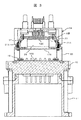
- FIG. 3 is a cross-sectional view illustrating a method of fixing a circuit board and a substrate support of the electric power steering device shown in FIG. 2.
- FIG. 4 is an enlarged sectional view of a part A shown in the electric power steering device shown in FIG. 3.
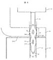
- FIG. 3 is a cross-sectional view illustrating a method of fixing a housing and a substrate support of the electric power steering device shown in FIG. 2.
- FIG. 6 is an enlarged sectional view of a portion B shown in the electric power steering device shown in FIG.
- the steering device 1 is configured as shown in FIG.
- a pinion (not shown) is provided at a lower end of the steering shaft 2 connected to a steering wheel (not shown), and this pinion is engaged with a rack (not shown) which is long in the left-right direction of the vehicle body.
- Tie rods 3 for steering the front wheels in the left-right direction are connected to both ends of the rack, and the rack is covered by a rack housing 4.
- a rubber boot 5 is provided between the rack housing 4 and the tie rod 3.
- An electric power steering device 6 is provided to assist the torque when rotating the steering wheel. That is, a torque sensor 7 for detecting a turning direction and a turning torque of the steering shaft 2 is provided, and an electric motor unit 8 for applying a steering assist force to the rack via the gear 10 based on a detection value of the torque sensor 7. And an electronic control unit (ECU) 9 for controlling the electric motor disposed in the electric motor unit 8.
- the electric motor unit 8 of the electric power steering device 6 has an outer peripheral portion on the output shaft side connected to the gear 10 via a screw (not shown), and an electronic control unit on the opposite side to the output shaft of the electric motor 8 portion. 9 are provided.
- the torque sensor 7 determines the rotation direction and the rotation torque of the steering shaft 2.
- the electronic control unit 9 calculates the driving operation amount of the electric motor based on the detected value.
- the electric motor is driven by the power switching element of the electronic control unit 9 based on the calculated drive operation amount, and the output shaft of the electric motor is rotated so as to drive the steering shaft 2 in the same direction as the operation direction.
- the rotation of the output shaft of the electric motor is transmitted from a pinion (not shown) to a rack (not shown) via a gear 10 to steer the vehicle. Since these configurations and operations are already well known, further description will be omitted.
- the tip of a metal press-fit type connector terminal insert-molded in a connector body made of a synthetic resin has a through-hole formed in a circuit board. And is elastically engaged with and fixed to.
- the circuit board and the housing are generally fastened by fixing screws. In this case, the circuit board is screwed and fixed to the housing with the fixing screws, and then the press-fit connector terminals are connected to the circuit board through holes. And is elastically engaged with and fixed to.
- the embodiment of the present invention proposes an electric power steering device having the following configuration.
- a first terminal engagement hole is provided in a circuit board, and a second terminal engagement hole is provided in a substrate support that is disposed adjacent to the circuit board and supports the circuit board;
- a first elastic engagement portion that elastically engages the first terminal engagement hole with the press-fit type connector terminal; and a first elastic engagement portion that elastically engages the second terminal engagement hole adjacent to the first elastic engagement portion.
- the first elastic engaging portion is connected to the first elastic engaging portion while the press-fit connector terminal is inserted into the first terminal engaging hole and the second terminal engaging hole.
- the second elastic engaging portion is elastically engaged with the second terminal engaging hole, whereby the circuit board and the substrate support are integrally fixed.
- a first terminal engagement hole is provided in a substrate support on which a circuit board is supported, and a second terminal engagement hole is provided in a fixing portion disposed adjacent to the substrate support.
- a first elastic engagement portion elastically engaged with the first terminal engagement hole, and a first elastic engagement portion elastically engaged with the second terminal engagement hole adjacent to the first terminal engagement hole.
- a second elastic engaging portion that fits with the first elastic engaging portion in a state where the press-fit connector terminal is inserted into the first terminal engaging hole and the second terminal engaging hole.
- the second elastic engagement portions are elastically engaged with the second terminal engagement holes, and the substrate support and the fixed portion are integrally formed. To be fixed.
- the circuit board and the substrate support can be fixed by the press-fit connector terminal, or the housing and the substrate support can be fixed by the press-fit connector terminal.
- the electrical connection of the press-fit connector terminals and the indirect or direct fixing of the circuit board can be realized with a simple configuration.
- FIGS. 3 and 4 show cross sections of a fixed portion between the circuit board and the substrate support
- FIGS. 2 shows a cross section of a fixed part of the body and the substrate support.
- FIGS. 3 and 4 show examples in which the circuit board is directly fixed to the substrate support
- FIGS. 5 and 6 show that the circuit board is indirectly fixed to the housing via the substrate support. An example is shown.
- the electric motor unit 8 constituting the electric power steering device includes a motor housing 11 having a cylindrical portion made of aluminum or an aluminum-based metal such as an aluminum alloy, and a housing (not shown) housed in the motor housing 11. And an electric motor.
- the electric motor has a rotating shaft, and a pinion (not shown) is fixed to an output portion of the rotating shaft to transmit a rotating motion to the rack.
- the axis of the rotating shaft and the axis of the motor housing 11 substantially coincide with each other, and the electric motor can rotate inside the motor housing 11.
- the electronic control unit 9 is disposed on the opposite side to the output unit (pinion side) in the axial direction of the motor housing 11, and has a bottomed cylindrical (so-called cup-shaped) cover 12 (not shown) (not shown). (Made of metal). Thereby, the electronic control unit 9 has a liquid-tight structure.
- a socket 13 is formed on the side opposite to the motor housing 11.
- the socket 13 is provided with power supply-side sockets 13A and 13B connected to a power supply (battery) and sensors such as a steering angle sensor or a sensor / network-side socket connected to a CAN network.
- the power supply-side socket portions 13A and 13B are provided in pairs (two), and these are redundant sockets. The redundant system will be described later.
- a motor housing 11 is made of an aluminum alloy, and functions as a heat sink member that releases heat generated by an electric motor and heat generated by a power supply circuit unit and a power conversion circuit unit described later to the outside atmosphere. I have.
- the electric motor section 8 is constituted by the electric motor and the motor housing 11.
- the electronic control unit 9 is attached to the end wall 15 of the motor housing 11 on the opposite side of the pinion of the electric motor unit 8.
- the end wall 15 functions as a “housing” to which the electronic control unit 9 is attached.
- the electronic control section 9 includes a power conversion circuit board 16S having a power conversion circuit section mounted thereon, a power supply circuit board 17S having a power supply circuit section mounted thereon, a control circuit board 18S having a control circuit section mounted thereon, and a connector body 14. .
- circuit boards 16S, 17S, 18S are assembled in a state where they are stacked in a parallel relationship. It should be noted that the electronic components and electric components constituting the respective circuit units are not shown on the power conversion circuit board 16S, the power supply circuit board 17S, and the control circuit board 18S.
- the end wall 15 of the motor housing 11 is formed separately from the end wall 15 and is integrated with the motor housing 11 by screws or welding. It may be formed integrally by cutting.
- the power conversion circuit section, the power conversion circuit section, and the control circuit section constitute a redundant system, and constitute a dual system of the first electronic control section and the second electronic control section.
- the electric motor is controlled and driven by the first electronic control unit.
- the electric motor is switched to the second electronic control unit to control and drive the electric motor. It is something that comes to come.
- heat from the first electronic control unit is transmitted to the motor housing 11, and when an abnormality or failure occurs in the first electronic control unit, the first electronic control unit stops and the second electronic control unit operates. The heat from the second electronic control unit is transmitted to the motor housing 11.
- the first electronic control unit and the second electronic control unit are combined to function as a regular electronic control unit. If an abnormality or failure occurs in one of the electronic control units, the other electronic control unit uses an electric motor with half the capacity. Can be controlled and driven. In this case, the capacity of the electric motor is halved, but the so-called “power steering function” is ensured. Therefore, in a normal case, the heat of the first electronic control unit and the second electronic control unit is transmitted to the motor housing 11. In the present embodiment, the latter redundant system is adopted, and therefore, the power supply side socket portions 13A and 13B are provided in pairs.
- the electronic control unit 9 includes a power conversion circuit board 16S, a power supply circuit board 17S, a control circuit board 18S, and a connector main body 14, and the power is controlled in a direction away from the end wall 15 side.
- the conversion circuit board 16S, the power supply circuit board 17S, the board supports 21A and 21B, the control circuit board 18S, and the connector body 14 are arranged in this order and in a stacked state.
- the control circuit unit mounted on the control circuit board 18S has a function of generating a control signal for driving a switching element (MOSFET) of the power conversion circuit board 16S, and includes a microcomputer, peripheral circuits, and the like.
- MOSFET switching element
- the power supply circuit section mounted on the power supply circuit board 17S generates a power supply voltage for driving the control circuit section mounted on the control circuit board 18S and a power supply voltage for driving the power conversion circuit mounted on the power conversion circuit board 16S. It has a function to perform the operation, and includes a capacitor, a coil, a switching element, and the like.
- the power conversion circuit unit mounted on the power conversion circuit board 16S has a function of adjusting the power flowing through the motor winding of the electric motor, and includes switching elements and the like forming three-phase upper and lower arms.
- the electronic control unit 9 generates a large amount of heat mainly in the power conversion circuit unit and the power supply circuit unit, and heat of the power conversion circuit unit and the power supply circuit unit is radiated from the motor housing 11 mainly made of an aluminum alloy. Things.
- a connector body 14 made of a synthetic resin is provided between the control circuit board 18S and the cover, and is connected to a vehicle power supply (battery) and an external control device (not shown). Needless to say, the connector body 14 is electrically connected to the power conversion circuit board 16S, the power supply circuit board 17S, and the control circuit board 18S.
- the cover 12 accommodates the power conversion circuit board 16S, the power supply circuit board 17S, and the control circuit board 18S, and has a function of sealing them in a liquid-tight manner.
- the cover 12 is fixed to the motor housing 11. Have been.
- a power conversion circuit board 16S constituting a power conversion circuit is provided on the surface of the end wall 15 of the motor housing 11, and a switching element and the like are surface-mounted on the power conversion circuit board 16S.
- the power conversion circuit board 16 ⁇ / b> S is screwed and fixed to the end wall 15 by four fixing screws 19.
- the power conversion circuit board 16S is desirably formed of a metal substrate, so that heat generated by the switching element or the like can be efficiently radiated to the end wall 15.
- a metal substrate such as a glass epoxy substrate, and in this embodiment, it is made of a glass epoxy substrate.
- a projecting fixing portion 20 functioning as a part of a housing extending in a direction away from the end wall portion 15 in the direction of the rotation axis of the electric motor is formed. Functions as an electrical ground.
- the projecting fixing portions 20 are formed at an angle of 180 ° so as to face each other.
- the protrusion fixing portion 20 has a function of fixing a substrate support 21B made of a conductive metal having a function of fixing a substrate.
- the space formed by the protruding fixing portion 20 has a function of accommodating a switching element and the like constituting the power conversion circuit portion. Further, a terminal engagement hole 22 into which a press-fit connector terminal described later is inserted is formed on the upper surface side of the protruding fixing portion 20.
- the power supply circuit board 17S is made of a glass epoxy board, and board supports 21A are fixed at four corners with fixing screws. In addition, a pair of cutouts are formed which retreat inward in the radial direction and face each other. The notch has a function for accommodating one of the substrate supports 21B. Further, a terminal engagement hole 23 into which a press-fit type connector terminal described later is inserted is formed in the substrate support 21B.
- the flexible connector is a connection connector that can be bent freely, and can connect the power conversion circuit board 16S and the power supply circuit board 17S with the power conversion circuit board 16S and the power supply circuit board 17S arranged in parallel.
- the substrate support 21A made of a conductive metal is fixed to the power supply circuit board 17S at four corners with fixing screws 24, and is fixed to the opposite corners of the control circuit board 18S.
- the control circuit board 17 has a terminal engagement hole 25 into which a press-fit connector terminal described later is inserted.
- the board support 21A on the control circuit board 17S side also has a terminal engagement hole (see FIG. 4) into which a later-described press-fit connector terminal is inserted.
- the substrate support 21A is formed in a U-shape, one of which is fixed to the power supply circuit board 17S by a fixing screw 24, and the other is a press-fit type with the control circuit board 18S. Fixed with connector terminals.
- the substrate support 21B is formed in a deformed “S” shape, one of which is fixed to the protruding fixing portion 20 by a press-fit type connector terminal, and the other is in contact with the control circuit board 18S, and
- the control circuit board 18S is supported by being fixed to the board 18S with an adhesive or the like.
- the board support 21B is disposed between the board supports 21A described above, and suppresses the control circuit board 18S from bending near the center, thereby improving the reliability of the control circuit board 17S.
- the control circuit board 18S is made of a glass epoxy board, and the power supply circuit board 17S and the control circuit board 18S are connected by the flexible connector 26 so that the power conversion circuit board 16S and the power supply circuit board 17S are connected by the flexible connector. It is connected.
- the connector body 14 is disposed on the control circuit board 18S.
- the connector body 14 is made of a synthetic resin, and press-fit type connector terminals are embedded by insert molding.
- the press-fit type connector terminal includes a power supply side connector terminal connected to a power supply, a steering angle sensor and a rotation sensor, a sensor / network side connector terminal connected to a CAN network, a ground terminal, and the like.
- the power supply side connector terminal is also configured as a redundant system.
- Steps are formed at the four corners of the connector body 14, and press-fit type connector terminals 27 are embedded in the steps, and a part thereof is arranged so as to be exposed to the outside.
- the above-described press-fit type connector terminal 27 has a flat plate shape, and has two elastic engaging portions formed at the tip end side.
- the terminal engaging hole (see FIG. 4) is elastically engaged.
- the press-fit type connector terminals are also elastically provided in the terminal engagement holes 23 formed in the substrate support 21B and the terminal engagement holes 22 formed in the protruding fixing portion 20. Are engaged.
- FIG. 3 is a cross-sectional view taken along the rotation axis direction so as to pass through the substrate support 21A.
- the press-fit type connector terminal 27 is a terminal for grounding, and is a terminal for grounding electronic components and electric components mounted on the control circuit board 18S.
- the press-fit connector terminal 27 is connected to a press-fit connector terminal 34 shown in FIGS. 5 and 6 described later, and is connected inside the connector body 14. Specifically, the press-fit connector terminals 27 and the press-fit connector terminals 34 are integrally formed by punching. Further, since the press-fit connector terminals 27 and the press-fit connector terminals 34 need to have a mechanical fixing function, the thickness is determined to be a thickness satisfying the fixing function.
- the control circuit board 18S is disposed adjacent to the board support 21A when viewed in the axial direction of the motor housing, and has a terminal engagement hole 25 of the control circuit board 18S and a terminal engagement hole of the board support 21A.
- the positions of the control circuit board 18S and the substrate support 21A are determined such that the positions shown in FIG. 4 overlap each other.
- the press-fit type connector terminals 27 are inserted into the respective terminal engaging holes, and engage with the elastic engaging portions of the press-fit type connector terminals 27 to mechanically connect the control circuit board 18S and the board support 21A. And the press-fit connector terminal 27 and the control circuit board 18S are electrically connected.
- FIG. 4 shows an enlarged cross section of the portion A in FIG.
- a terminal engagement hole 25 functioning as a through hole is formed in a control circuit board 18S made of a glass epoxy board.
- a land 28 made of a conductive metal is formed in the terminal engagement hole 25, and the land 28 is connected to an electronic component or an electric component (not shown).
- a terminal engaging hole 29 is formed in the substrate support 21A made of metal.
- the center lines of the terminal engagement holes 25 and the terminal engagement holes 29 are respectively coincident. Therefore, the press-fit type connector terminal 27 can be inserted smoothly.
- the diameter of the terminal engagement hole 29 of the board support 21A is set to a value smaller than the diameter of the terminal engagement hole 25 of the control circuit board 18S. The reason will be described later.
- An insulating sheet 30 is interposed between the control circuit board 18S and the board support 21A to electrically insulate them. However, if there is a sufficient gap between the control circuit board 18S and the board support 21A, the insulating sheet 30 is not always necessary.
- the press-fit type connector terminal 27 is formed in an elongated flat plate shape, and has a pointed end portion 31 formed in a pointed shape on the distal end side.
- a support-side elastic engaging portion 32 having a large width from the front end side and a substrate-side elastic engaging portion 33 having a large width also are formed.
- the support-side elastic engagement portion 32 is elastically engaged with the terminal engagement hole 29 of the substrate support 21A, and similarly, the substrate-side elastic engagement portion 33 is elastically engaged with the terminal engagement hole 25 of the control circuit board 18S. Engaged.
- the two elastic engaging portions 32 and 33 are also formed adjacent to each other in accordance with the arrangement of the control circuit board 18S and the board support 21A. For this reason, the distance between the control circuit board 18S and the board support 21A is shortened, the bending moment acting on each other is not increased, and the reliability of the mechanical fixing function can be improved.
- Openings 32H and 33H are formed at the center of the respective elastic engaging portions 32 and 33.
- the areas of the openings 32H and 33H are elastically deformed and elastically deform in a direction orthogonal to the insertion direction. Give power.
- a predetermined holding force mainly a frictional force
- the width WA of the support-side elastic engagement portion 32 is set to a length corresponding to the terminal engagement hole 29 of the substrate support 21A
- the width WS of the substrate-side elastic engagement portion 33 is also set to the control circuit board 18S.
- the length is set in accordance with the terminal engagement hole 25 of FIG. That is, the widths WA and WS of the respective elastic engagement portions 32 and 33 are set to a predetermined value when the respective elastic engagement portions 32 and 33 are elastically engaged with the respective terminal engagement holes 29 and 25. It is determined so that a force (mainly frictional force) can be obtained.
- the diameter of the terminal engagement hole 29 of the board support 21A is set to a value smaller than the diameter of the terminal engagement hole 25 of the control circuit board 18S. The reason is as follows. That is, when the press-fit type connector terminal 27 is inserted from the control circuit board 18S side, the terminal engagement hole 25 of the control circuit board 18S is first inserted by the support side elastic engagement portion 32.
- the terminal engagement hole 25 is set smaller, the width WA of the support-side elastic engagement portion 32 of the press-fit connector terminal 27 is large. 32 cannot be inserted well.
- the press-fit type connector terminal 27 is inserted from the side of the substrate support 21A, the relationship is reversed.
- the length of the board-side elastic engaging portion 33 is determined in accordance with the axial length LS of the terminal engaging hole 25 of the control circuit board 18S.
- the length LA of the support-side elastic engaging portion 32 is determined according to the length LS in the direction. Therefore, in order to increase the holding force, the lengths LS, LA of the respective terminal engagement holes 25, 29 can be increased, and similarly, the lengths of the respective elastic engagement portions 32, 33 can be increased. is there.
- press-fit type connector terminal 27 is for a ground terminal
- a press-fit type connector terminal which will be described later, is connected to the ground terminal of the control circuit board 18S via the land 28 and the board-side elastic engaging portion 33.
- An earth circuit is formed toward.
- the control circuit board 18S and the substrate-side elastic engagement portion 33 are elastically engaged and fixed.
- the control circuit board 18S can be fixed to the board support 21A without using fixing screws or the like. Further, since the press-fit type connector terminals 27 are merely inserted into the terminal engagement holes 25 and 29 of the control circuit board 18S and the board support 21A, the number of working steps such as forming fixing screws can be reduced.
- the press-fit type connector terminal 27 is used for the ground terminal.
- the press-fit type connector terminal 27 is used only for fixing the control circuit board 18S and the board support 21A without passing a current. Of course, it is possible.
- the power supply circuit board 17S is used instead of the control circuit board 18S, it is possible to use only the press-fit type connector terminal 27 and use it as a power supply connector terminal.
- the current from the power supply is supplied to the power supply circuit of the power supply circuit board 17S via the press-fit type connector terminal 27, and the board support 21A and the power supply circuit board 17S are fixed to each other by the press-fit type connector terminal 27. .
- the substrate support 21A and the support-side elastic engaging portion 32 are elastically engaged and fixed, and the control circuit board 18S and the substrate-side elastic engaging portion 33 are elastically engaged and fixed. Therefore, the control circuit board 18S can be fixed without using fixing screws or the like for the substrate support 21A. Further, since the press-fit type connector terminals 27 are merely inserted into the terminal engagement holes 25 and 29 of the control circuit board 18S and the board support 21A, the number of working steps such as formation of fixing screws can be reduced.
- FIG. 5 is a cross-sectional view taken along the rotation axis direction so as to pass through the substrate support 21B.
- the press-fit type connector terminal 34 is a terminal for grounding, and is a terminal for grounding an electronic component or an electrical component mounted on the control circuit board 18S to the protruding fixing portion 20.
- the bent fixing portion of the substrate support 21B is disposed adjacent to the protruding fixing portion 20 which is a housing, and has a terminal engaging hole 23 of the substrate supporting member 21B and a terminal engaging hole 22 of the protruding fixing portion 20.
- the positions of the substrate support 21 ⁇ / b> B and the protruding fixing part 20 are determined so that the two overlap.
- the press-fit type connector terminal 34 is inserted into each of the terminal engagement holes 22 and 23, and engages with the elastic engagement portion of the press-fit type connector terminal 34, so that the board support 21B and the protrusion fixing portion 20 Are mechanically fixed, and the press-fit connector terminal 34 and the protruding fixing portion 20 are electrically connected.
- the protrusion fixing portion 20 is grounded to the motor housing 11.
- FIG. 6 shows an enlarged cross section of a portion B in FIG.
- a terminal engaging hole 23 is formed in a bent fixing portion 35 of a substrate support 21B made of metal.
- a terminal engaging hole 22 is formed in the protruding fixing portion 20 made of a conductive metal.
- the center lines of the terminal engaging hole 23 and the terminal engaging hole 22 are respectively coincident. Therefore, the press-fit type connector terminal 34 can be smoothly inserted.
- the diameter of the terminal engagement hole 23 is set to a value smaller than the diameter of the terminal engagement hole 22. The reason will be described later.
- Press-fit connector terminals 34 that mechanically fix the substrate support 21B and the protruding fixing portion 20 and that are electrically connected to the protruding fixing portion 20 are inserted through the respective terminal engaging holes 23 and 22. I have.
- the press-fit type connector terminal 34 is formed in an elongated flat plate shape, and has a pointed portion 36 formed in a pointed shape on the distal end side.
- a fixed portion side elastic engagement portion 37 and a support body side elastic engagement portion 38 are formed from the pointed end side.
- the fixed portion side elastic engaging portion 37 is elastically engaged with the terminal engaging hole 22 of the projecting fixing portion 20, and similarly, the support side elastic engaging portion 38 is elastically engaged with the terminal engaging hole 23 of the substrate support 21B. Is engaged.
- the two elastic engaging portions 37 and 38 are also formed adjacent to each other in accordance with the arrangement of the projecting fixing portion 20 and the substrate support 21A. For this reason, the distance between the projecting fixing portion 20 and the substrate support 21A is shortened, the bending moment acting on each other is not increased, and the reliability of mechanical fixing can be improved.
- Openings 37H and 38H are formed at the center of the respective elastic engaging portions 37 and 38.
- the areas of the openings 32H and 33H are elastically deformed and elastically deform in a direction orthogonal to the insertion direction. Give power. Thereby, a predetermined holding force (mainly a frictional force) is obtained.
- the width WE of the fixed portion side elastic engagement portion 37 is set to a length corresponding to the terminal engagement hole 22 of the projecting fixed portion 20, and the width WB of the support side elastic engagement portion 38 is The length is set in accordance with the terminal engagement hole 23 of 21B. That is, the widths WE and WB of the respective elastic engagement portions 37 and 38 are such that a predetermined holding force (mainly a frictional force) is obtained when the elastic engagement portions 37 and 38 are elastically engaged with the respective terminal engagement holes 22 and 23. It is decided to.
- a predetermined holding force mainly a frictional force
- the diameter of the terminal engaging hole 22 of the protruding fixing portion 20 is set to a value smaller than the diameter of the terminal engaging hole 23 of the substrate support 21B.
- the reason is as follows. That is, when the press-fit type connector terminal 34 is inserted from the substrate support 21B side, the terminal engaging hole 23 of the substrate support 21B is first inserted by the fixed portion side elastic engaging portion 37. For this reason, when the terminal engagement hole 23 is set smaller, the width WE of the fixed portion side elastic engagement portion 37 of the press-fit type connector terminal 34 is large, so that the fixed portion side elastic engagement portion This is because the joint 37 cannot be inserted properly.
- the length of the support-side elastic engaging portion 38 is determined in accordance with the axial length LB of the terminal engaging hole 23 of the substrate support 21B.
- the length of the fixed portion side elastic engagement portion 37 is determined according to the length. Note that the length of the fixed portion side elastic engagement portion 37 can be determined to any length as long as it is within the length of the protruding fixed portion 20. Therefore, in order to increase the holding force, the lengths LS, LA of the respective terminal engagement holes 25, 29 can be increased, and similarly, the lengths of the respective elastic engagement portions 32, 33 can be increased. is there.
- the press-fit type connector terminal 34 is for an earth terminal
- an earth circuit is formed from the press-fit type connector terminal 27 to the projecting fixing part 20 via the fixing part side elastic engaging part 37.
- the protruding fixing portion 20 and the fixing portion side elastic engaging portion 37 are elastically engaged and fixed, and similarly, the substrate support 21B and the support side elastic engaging portion 38 are elastically engaged and fixed. Therefore, the substrate support 21B can be fixed to the protruding fixing portion 20 without using a fixing screw or the like.
- the press-fit type connector terminal 34 is merely inserted into the board support 21B and the terminal engaging holes 22 and 23 of the protruding fixing part 20, the number of manufacturing steps such as formation of fixing screws can be reduced.
- the press-fit type connector terminal 34 is used for the ground terminal.
- the press-fit type connector terminal 34 may be used merely for fixing the substrate support 21B and the protruding fixing portion 20 without passing an electric current. it can.
- the configuration in which the substrate support 21A and the substrate support 21B are separated is shown.
- the substrate support 21A and the substrate support 21B are integrated to form an annular substrate support.
- the electronic component and the electrical component that constitute the power supply circuit may be housed in a space formed inside.
- a control circuit board is arranged on the upper surface side of the substrate support (annular) and fixed with press-fit connector terminals
- a power supply circuit board is arranged on the lower surface side of the substrate support (annular) and fixed with screws.
- the substrate support and the protruding fixing portion may be fixed by press-fit connector terminals.
- the first terminal engagement hole is provided in the circuit board
- the second terminal engagement hole is provided in the substrate support that is disposed adjacent to the circuit board and supports the circuit board.
- a first elastic engagement portion elastically engaged with the first terminal engagement hole
- a first elastic engagement portion elastically engaged with the second terminal engagement hole adjacent to the first terminal engagement hole.
- a second elastic engaging portion that fits with the first elastic engaging portion in a state where the press-fit connector terminal is inserted into the first terminal engaging hole and the second terminal engaging hole.
- the second elastic engagement portions are elastically engaged with the second terminal engagement holes, and the circuit board and the substrate support are integrally formed. To be fixed.
- the first terminal engagement hole is provided in the substrate support on which the circuit board is supported, and the second terminal engagement hole is provided in the fixing portion arranged adjacent to the substrate support.
- a first elastic engagement portion elastically engaged with the first terminal engagement hole, and a first elastic engagement portion elastically engaged with the second terminal engagement hole adjacent to the first terminal engagement hole.
- a second elastic engaging portion that fits with the first elastic engaging portion in a state where the press-fit connector terminal is inserted into the first terminal engaging hole and the second terminal engaging hole.
- the second elastic engagement portions are elastically engaged with the second terminal engagement holes, and the substrate support and the fixed portion are integrally formed. To be fixed.
- the circuit board and the substrate support can be fixed by the press-fit connector terminal, or the housing and the substrate support can be fixed by the press-fit connector terminal.
- the electrical connection of the press-fit connector terminals and the indirect or direct fixing of the circuit board can be realized with a simple configuration.
- the present invention is not limited to the above-described embodiment, but includes various modifications.
- the above-described embodiments have been described in detail in order to explain the present invention in an easy-to-understand manner, and are not necessarily limited to those having all the described configurations.
- a part of the configuration of one embodiment can be replaced with the configuration of another embodiment, and the configuration of one embodiment can be added to the configuration of another embodiment.
Landscapes
- Engineering & Computer Science (AREA)
- Power Engineering (AREA)
- Chemical & Material Sciences (AREA)
- Combustion & Propulsion (AREA)
- Transportation (AREA)
- Mechanical Engineering (AREA)
- Microelectronics & Electronic Packaging (AREA)
- Power Steering Mechanism (AREA)
Abstract
Un dispositif selon la présente invention comprend : un premier trou de mise en prise de borne (29) disposé sur un corps de support de carte (21A) sur lequel une carte de circuit imprimé (18S) est supportée, un second trou de mise en prise de borne (25) disposé sur la carte de circuit imprimé (18S) placée de manière adjacente au corps de support de carte (21A). Sur une borne de connexion de type à ajustement par serrage (27), sont formées une première partie de mise en prise élastique (32) qui vient en prise élastiquement avec le premier trou de mise en prise de borne (29), et une seconde partie de mise en prise élastique (33) qui vient en prise élastiquement avec le second trou de mise en prise de borne (25). Dans un état dans lequel la borne de connexion de type à ajustement par serrage (27) est insérée dans le premier trou de mise en prise de borne (29) et le second trou de mise en prise de borne (25), la première partie de mise en prise élastique (32) est mise en prise élastiquement dans le premier trou de mise en prise de borne (29) et la seconde partie de mise en prise élastique (33) est mise en prise élastiquement dans le second trou de mise en prise de borne (25), de sorte à fixer en une seule pièce la carte de circuit imprimé (18S) et le corps de support de carte (21a). A l'aide de ces configurations, il est possible de réaliser facilement une connexion électrique de la borne de connexion de type à ajustement par serrage, et de fixer la carte de circuit imprimé (y compris par fixation directe, et par fixation indirecte).
Priority Applications (2)
| Application Number | Priority Date | Filing Date | Title |
|---|---|---|---|
| DE112019003396.4T DE112019003396T5 (de) | 2018-07-02 | 2019-06-21 | Elektrische antriebsvorrichtung und elektrische servolenkvorrichtung |
| US17/255,631 US20210265899A1 (en) | 2018-07-02 | 2019-06-21 | Electrical drive device and electrical power steering device |
Applications Claiming Priority (2)
| Application Number | Priority Date | Filing Date | Title |
|---|---|---|---|
| JP2018-126090 | 2018-07-02 | ||
| JP2018126090A JP7122180B2 (ja) | 2018-07-02 | 2018-07-02 | 電動駆動装置、及び電動パワーステアリング装置 |
Publications (1)
| Publication Number | Publication Date |
|---|---|
| WO2020008905A1 true WO2020008905A1 (fr) | 2020-01-09 |
Family
ID=69060590
Family Applications (1)
| Application Number | Title | Priority Date | Filing Date |
|---|---|---|---|
| PCT/JP2019/024623 Ceased WO2020008905A1 (fr) | 2018-07-02 | 2019-06-21 | Dispositif de commande électrique et dispositif de direction assistée électrique |
Country Status (4)
| Country | Link |
|---|---|
| US (1) | US20210265899A1 (fr) |
| JP (1) | JP7122180B2 (fr) |
| DE (1) | DE112019003396T5 (fr) |
| WO (1) | WO2020008905A1 (fr) |
Cited By (1)
| Publication number | Priority date | Publication date | Assignee | Title |
|---|---|---|---|---|
| CN113541407A (zh) * | 2021-06-30 | 2021-10-22 | 杭州微光电子股份有限公司 | 一种能够增强散热的外转子电机 |
Families Citing this family (3)
| Publication number | Priority date | Publication date | Assignee | Title |
|---|---|---|---|---|
| JP7359022B2 (ja) * | 2020-02-14 | 2023-10-11 | 株式会社デンソー | 駆動装置 |
| US11839017B2 (en) * | 2021-08-05 | 2023-12-05 | Te Connectivity Solutions Gmbh | Thermal press-fit terminal |
| DE102022213521A1 (de) * | 2022-12-13 | 2024-06-13 | Robert Bosch Gesellschaft mit beschränkter Haftung | Steuergerät und Verfahren zur Montage des Steuergeräts |
Citations (3)
| Publication number | Priority date | Publication date | Assignee | Title |
|---|---|---|---|---|
| JPS60227372A (ja) * | 1984-04-25 | 1985-11-12 | 株式会社日立製作所 | 圧入端子 |
| JPH09167661A (ja) * | 1995-12-15 | 1997-06-24 | Fujitsu Takamizawa Component Kk | 多芯同軸ジャック |
| JP2016127780A (ja) * | 2015-01-08 | 2016-07-11 | 株式会社デンソー | 駆動装置 |
Family Cites Families (6)
| Publication number | Priority date | Publication date | Assignee | Title |
|---|---|---|---|---|
| JPH1021984A (ja) * | 1996-06-28 | 1998-01-23 | Yazaki Corp | コネクタ端子の圧入構造 |
| JP4111796B2 (ja) * | 2002-10-11 | 2008-07-02 | 富士通テン株式会社 | プレスフィット端子圧入方法 |
| JP2015226440A (ja) * | 2014-05-29 | 2015-12-14 | 日本精機株式会社 | 電気式計器装置 |
| US20160190718A1 (en) * | 2014-12-31 | 2016-06-30 | Borgwarner Inc. | Blind electrical connector between printed circuit board and solenoid member |
| JP7024320B2 (ja) * | 2016-11-07 | 2022-02-24 | 株式会社デンソー | モータ |
| JP7291572B2 (ja) * | 2019-08-21 | 2023-06-15 | 日立Astemo株式会社 | 電動駆動装置及び電動駆動装置の組立方法 |
-
2018
- 2018-07-02 JP JP2018126090A patent/JP7122180B2/ja active Active
-
2019
- 2019-06-21 DE DE112019003396.4T patent/DE112019003396T5/de not_active Withdrawn
- 2019-06-21 US US17/255,631 patent/US20210265899A1/en not_active Abandoned
- 2019-06-21 WO PCT/JP2019/024623 patent/WO2020008905A1/fr not_active Ceased
Patent Citations (3)
| Publication number | Priority date | Publication date | Assignee | Title |
|---|---|---|---|---|
| JPS60227372A (ja) * | 1984-04-25 | 1985-11-12 | 株式会社日立製作所 | 圧入端子 |
| JPH09167661A (ja) * | 1995-12-15 | 1997-06-24 | Fujitsu Takamizawa Component Kk | 多芯同軸ジャック |
| JP2016127780A (ja) * | 2015-01-08 | 2016-07-11 | 株式会社デンソー | 駆動装置 |
Cited By (2)
| Publication number | Priority date | Publication date | Assignee | Title |
|---|---|---|---|---|
| CN113541407A (zh) * | 2021-06-30 | 2021-10-22 | 杭州微光电子股份有限公司 | 一种能够增强散热的外转子电机 |
| CN113541407B (zh) * | 2021-06-30 | 2022-06-10 | 杭州微光电子股份有限公司 | 一种能够增强散热的外转子电机 |
Also Published As
| Publication number | Publication date |
|---|---|
| JP2020001667A (ja) | 2020-01-09 |
| US20210265899A1 (en) | 2021-08-26 |
| JP7122180B2 (ja) | 2022-08-19 |
| DE112019003396T5 (de) | 2021-04-01 |
Similar Documents
| Publication | Publication Date | Title |
|---|---|---|
| US11870326B2 (en) | Electric drive apparatus, and electric power steering apparatus | |
| JP6443055B2 (ja) | 駆動装置、および、駆動装置の製造方法 | |
| JP6837257B2 (ja) | 電動駆動装置及び電動パワーステアリング装置 | |
| JP6863875B2 (ja) | 電動駆動装置及び電動パワーステアリング装置 | |
| JP7291572B2 (ja) | 電動駆動装置及び電動駆動装置の組立方法 | |
| WO2016163037A1 (fr) | Dispositif de direction assistée électrique | |
| JP6610225B2 (ja) | 駆動装置 | |
| WO2020008905A1 (fr) | Dispositif de commande électrique et dispositif de direction assistée électrique | |
| JP7063747B2 (ja) | 電動駆動装置及び電動パワーステアリング装置 | |
| US20240006954A1 (en) | Drive device | |
| JP6485032B2 (ja) | 駆動装置、および、これを用いた電動パワーステアリング装置 | |
| CN111052570B (zh) | 电动驱动装置及电动助力转向装置 | |
| CN110892616B (zh) | 电动驱动装置及电动动力转向装置 | |
| WO2016174704A1 (fr) | Dispositif de commande | |
| JP2016146702A (ja) | 電動駆動装置及び電動パワーステアリング装置 | |
| JP6864029B2 (ja) | 電動駆動装置 | |
| JP6909689B2 (ja) | 電動駆動装置及び電動パワーステアリング装置 | |
| JP5967425B2 (ja) | 電動パワーステアリング装置 | |
| WO2020137568A1 (fr) | Dispositif de commande électronique et dispositif de guidage d'alimentation électrique | |
| JP7041546B2 (ja) | 電子制御装置、及び電動駆動装置 | |
| US20200406959A1 (en) | Electrical drive device and electrical power steering device | |
| JP7085439B2 (ja) | 電動駆動装置、及び電動パワーステアリング装置 | |
| JP2022026387A (ja) | モータ制御装置、および電動パワーステアリング装置 | |
| JP2018207748A (ja) | 電源装置 |
Legal Events
| Date | Code | Title | Description |
|---|---|---|---|
| 121 | Ep: the epo has been informed by wipo that ep was designated in this application |
Ref document number: 19831108 Country of ref document: EP Kind code of ref document: A1 |
|
| 122 | Ep: pct application non-entry in european phase |
Ref document number: 19831108 Country of ref document: EP Kind code of ref document: A1 |