WO2020008908A1 - 通信装置、及び通信方法 - Google Patents
通信装置、及び通信方法 Download PDFInfo
- Publication number
- WO2020008908A1 WO2020008908A1 PCT/JP2019/024641 JP2019024641W WO2020008908A1 WO 2020008908 A1 WO2020008908 A1 WO 2020008908A1 JP 2019024641 W JP2019024641 W JP 2019024641W WO 2020008908 A1 WO2020008908 A1 WO 2020008908A1
- Authority
- WO
- WIPO (PCT)
- Prior art keywords
- information
- frame
- base station
- redundancy
- communication device
- Prior art date
- Legal status (The legal status is an assumption and is not a legal conclusion. Google has not performed a legal analysis and makes no representation as to the accuracy of the status listed.)
- Ceased
Links
Images






Classifications
-
- H—ELECTRICITY
- H04—ELECTRIC COMMUNICATION TECHNIQUE
- H04L—TRANSMISSION OF DIGITAL INFORMATION, e.g. TELEGRAPHIC COMMUNICATION
- H04L1/00—Arrangements for detecting or preventing errors in the information received
- H04L1/22—Arrangements for detecting or preventing errors in the information received using redundant apparatus to increase reliability
-
- H—ELECTRICITY
- H04—ELECTRIC COMMUNICATION TECHNIQUE
- H04L—TRANSMISSION OF DIGITAL INFORMATION, e.g. TELEGRAPHIC COMMUNICATION
- H04L1/00—Arrangements for detecting or preventing errors in the information received
- H04L1/12—Arrangements for detecting or preventing errors in the information received by using return channel
- H04L1/16—Arrangements for detecting or preventing errors in the information received by using return channel in which the return channel carries supervisory signals, e.g. repetition request signals
- H04L1/18—Automatic repetition systems, e.g. Van Duuren systems
- H04L1/1867—Arrangements specially adapted for the transmitter end
- H04L1/1896—ARQ related signaling
-
- H—ELECTRICITY
- H04—ELECTRIC COMMUNICATION TECHNIQUE
- H04L—TRANSMISSION OF DIGITAL INFORMATION, e.g. TELEGRAPHIC COMMUNICATION
- H04L1/00—Arrangements for detecting or preventing errors in the information received
-
- H—ELECTRICITY
- H04—ELECTRIC COMMUNICATION TECHNIQUE
- H04L—TRANSMISSION OF DIGITAL INFORMATION, e.g. TELEGRAPHIC COMMUNICATION
- H04L1/00—Arrangements for detecting or preventing errors in the information received
- H04L1/08—Arrangements for detecting or preventing errors in the information received by repeating transmission, e.g. Verdan system
-
- H—ELECTRICITY
- H04—ELECTRIC COMMUNICATION TECHNIQUE
- H04L—TRANSMISSION OF DIGITAL INFORMATION, e.g. TELEGRAPHIC COMMUNICATION
- H04L1/00—Arrangements for detecting or preventing errors in the information received
- H04L1/12—Arrangements for detecting or preventing errors in the information received by using return channel
- H04L1/16—Arrangements for detecting or preventing errors in the information received by using return channel in which the return channel carries supervisory signals, e.g. repetition request signals
- H04L1/18—Automatic repetition systems, e.g. Van Duuren systems
- H04L1/1867—Arrangements specially adapted for the transmitter end
- H04L1/189—Transmission or retransmission of more than one copy of a message
-
- H—ELECTRICITY
- H04—ELECTRIC COMMUNICATION TECHNIQUE
- H04W—WIRELESS COMMUNICATION NETWORKS
- H04W72/00—Local resource management
- H04W72/04—Wireless resource allocation
- H04W72/044—Wireless resource allocation based on the type of the allocated resource
- H04W72/0453—Resources in frequency domain, e.g. a carrier in FDMA
-
- H—ELECTRICITY
- H04—ELECTRIC COMMUNICATION TECHNIQUE
- H04W—WIRELESS COMMUNICATION NETWORKS
- H04W72/00—Local resource management
- H04W72/50—Allocation or scheduling criteria for wireless resources
- H04W72/56—Allocation or scheduling criteria for wireless resources based on priority criteria
-
- H—ELECTRICITY
- H04—ELECTRIC COMMUNICATION TECHNIQUE
- H04W—WIRELESS COMMUNICATION NETWORKS
- H04W84/00—Network topologies
- H04W84/02—Hierarchically pre-organised networks, e.g. paging networks, cellular networks, WLAN [Wireless Local Area Network] or WLL [Wireless Local Loop]
- H04W84/10—Small scale networks; Flat hierarchical networks
- H04W84/12—WLAN [Wireless Local Area Networks]
Definitions
- the present technology relates to a communication device and a communication method, and in particular, to a communication device and a communication method capable of realizing communication with high reliability and low delay.
- Patent Document 1 discloses a technique for simultaneously transmitting the same PDU (Protocol Data Unit) on a plurality of channels in order to enhance the robustness of the system.
- PDU Protocol Data Unit
- the present technology has been made in view of such a situation, and is intended to realize communication with high reliability and low delay.
- a communication device is a base station, generates redundancy information on redundancy of transmission data transmitted by a terminal station or the base station, and multiplex information on multiplexing of the transmission data,
- a communication device including a control unit that controls transmission of the generated redundancy information and the multiplexed information to the terminal station.
- a communication device of a base station generates redundancy information on redundancy of transmission data transmitted by a terminal station or the base station, and multiplex information on multiplexing of the transmission data.
- redundancy information on redundancy of transmission data transmitted by a terminal station or a base station and multiplexing information on multiplexing of the transmission data are generated and generated.
- the redundancy information and the multiplexing information are transmitted to the terminal station.
- a communication device is a terminal station, redundancy information transmitted from a base station and related to redundancy of transmission data transmitted by the terminal station or the base station, and multiplexing of the transmission data.
- the communication method is a communication device of a terminal station, transmitted from a base station, redundancy information on redundancy of transmission data transmitted by the terminal station or the base station, and the transmission data Receiving multiplexing information related to multiplexing, based on the received redundancy information and the multiplexing information, transmitting a multiplexed first frame that is a frame including the transmission data to the base station, Or a communication method for receiving the multiplexed first frame transmitted from the base station.
- the present invention relates to redundancy information relating to redundancy of transmission data transmitted from a terminal station or the base station, transmitted from a base station, and multiplexing of the transmission data. Multiplexing information is received, and based on the received redundancy information and the multiplexing information, a frame including the transmission data and a multiplexed first frame is transmitted to the base station, or The multiplexed first frame transmitted from the base station is received.
- the communication device may be an independent device or may be an internal block configuring one device.
- FIG. 2 is a diagram illustrating an example of a configuration of a wireless communication system.
- FIG. 1 is a block diagram illustrating an example of a configuration of an embodiment of a communication device to which the present technology is applied.
- FIG. 5 is a diagram schematically illustrating realization of high reliability by repeated transmission on a time axis according to a current method.
- FIG. 7 is a diagram schematically illustrating realization of high reliability and low delay by repetitive transmission on a frequency axis according to a new method. It is the figure which represented the effect of the interference avoidance by a new system typically.
- FIG. 9 is a diagram schematically illustrating an example of a case where different bandwidths are allocated by a new method.
- FIG. 7 is a diagram schematically illustrating an example of a case where repetitive transmission on the frequency axis is performed during downlink communication according to a new method. It is a figure showing the example of the format of an extended trigger frame. It is a figure showing an example of a format of a prior notice frame.
- 9 is a flowchart illustrating a flow of a first example of processing of a base station and a terminal station. 9 is a flowchart illustrating a flow of a second example of the processing of the base station and the terminal station.
- FIG. 21 is a block diagram illustrating an example of another configuration of an embodiment of a communication device to which the present technology is applied.
- FIG. 21 is a block diagram illustrating an example of another configuration of an embodiment of a communication device to which the present technology is applied.
- FIG. 1 is a diagram illustrating an example of a configuration of a wireless communication system.
- the wireless communication system includes a plurality of networks (BSS: Basic ⁇ Service ⁇ Set) including a base station (AP: Access @ Point) and a terminal station (STA: Station) serving as a subordinate terminal connected to the base station.
- BSS Basic ⁇ Service ⁇ Set
- AP Access @ Point
- STA Terminal station
- the network BSS1 is composed of the base station AP1 and the terminal stations STA1a and STA1b connected to the base station AP1. Note that a dotted line connecting the base station AP1 to the terminal stations STA1a and STA1b indicates that they are connected. Although not shown, the terminal stations STA are also connected to the base stations AP2 to AP4 in the same manner as the base station AP1, forming networks BSS2 to BSS4, respectively.
- each base station AP indicates the communicable range of each base station AP, that is, the signal arrival range and signal detection range.
- the communicable range of each base station AP may overlap.
- the communicable range of the base station AP2 includes the base station AP1 and the base station AP3.
- the configuration of the wireless communication system shown in FIG. 1 is an example, and the numbers and arrangements of the base station AP, the terminal station STA, and the network BSS are not limited thereto.
- FIG. 2 is a block diagram illustrating a configuration example of an embodiment of a communication device (wireless communication device) to which the present technology is applied.
- the communication device 10 shown in FIG. 2 is configured as a base station AP or a terminal station STA in the wireless communication system of FIG.
- the communication device 10 includes a control unit 101, a data processing unit 102, a communication unit 103, and a power supply unit 104.
- the communication unit 103 includes a modulation / demodulation unit 111, a signal processing unit 112, a channel estimation unit 113, wireless interface units 114-1 to 114-N (N: an integer equal to or greater than 1), and amplifier units 115-1 to 115-N. (N: an integer of 1 or more).
- the antennas 116-1 to 116-N (N: an integer equal to or greater than 1) are provided for the communication unit 103 (the amplifier units 115-1 to 115-N).
- the control unit 101 includes, for example, a microprocessor or a microcontroller, and controls the operation of each unit. Further, the control unit 101 exchanges information (data) between blocks.
- the control unit 101 performs packet scheduling in the data processing unit 102 and parameter setting in the modulation / demodulation unit 111 and the signal processing unit 112 of the communication unit 103. Further, the control unit 101 performs parameter setting and transmission power control of the wireless interface units 114-1 to 114-N and the amplifier units 115-1 to 115-N.
- the data processing unit 102 generates a packet for wireless communication from the input data at the time of transmission when data is input from the protocol upper layer, and adds a header for media access control (MAC). Or, processing such as addition of an error detection code is performed, and the processing data obtained as a result is output to (the modulation / demodulation section 111 of) the communication section 103.
- MAC media access control
- the data processing unit 102 performs processing such as analysis of a MAC header, detection of a packet error, and reorder processing on the input data at the time of reception of data input from (the modulation / demodulation unit 111 of) the communication unit 103. And outputs the processing data obtained as a result to the protocol upper layer.
- the communication unit 103 performs a process related to wireless communication according to the control from the control unit 101.
- the modulation / demodulation unit 111 performs processing such as encoding, interleaving, and modulation on input data input from the data processing unit 102 based on the coding and modulation scheme set by the control unit 101.
- the obtained data symbol stream is output to signal processing section 112.
- the modulation / demodulation unit 111 performs demodulation, on the data symbol stream input from the signal processing unit 112, based on the opposite process at the time of transmission, that is, based on the coding and demodulation scheme set by the control unit 101. Processing such as deinterleaving and decoding is performed, and processing data obtained as a result is output to the control unit 101 or the data processing unit 102.
- the signal processing unit 112 performs processing such as signal processing provided for spatial separation on the data symbol stream input from the modulation / demodulation unit 111 as necessary, and obtains one or more transmission symbols obtained as a result.
- the streams are output to the wireless interface units 114-1 to 114-N, respectively.
- the signal processing unit 112 performs processing such as signal processing for spatial decomposition of the stream on the received symbol stream input from each of the radio interface units 114-1 to 114-N as necessary. And outputs the resulting data symbol stream to the modem 111.
- the channel estimation unit 113 calculates the complex channel gain information of the propagation path from the preamble part and the training signal part of the input signals from each of the radio interface units 114-1 to 114-N.
- the complex channel gain information calculated by the channel estimation unit 113 is used for demodulation processing in the modulation / demodulation unit 111 via the control unit 101 and spatial processing in the signal processing unit 112.
- the radio interface unit 114-1 converts a transmission symbol stream input from the signal processing unit 112 into an analog signal, performs processing such as filtering and up-conversion to a carrier frequency, and obtains the result.
- the transmission signal is output (transmitted) to the amplifier 115-1 or the antenna 116-1.
- the radio interface unit 114-1 upon reception, performs a process opposite to that at the time of transmission, that is, a process such as down-conversion, on the received signal input from the amplifier unit 115-1 or the antenna 116-1.
- the resulting received symbol stream is output to signal processing section 112.
- the amplifier 115-1 amplifies the transmission signal (analog signal) input from the wireless interface 114-1 to a predetermined power, and transmits the signal to the antenna 116-1.
- the amplifier unit 115-1 amplifies a reception signal (analog signal) input from the antenna 116-1 to a predetermined power and outputs the signal to the wireless interface unit 114-1.
- the wireless interface units 114-2 to 114-N have the same configuration as the wireless interface unit 114-1, and the amplifier units 115-2 to 115-N have the same configuration as the amplifier unit 115-1. Since the antennas 116-2 to 116-N are configured in the same manner as the antenna 116-1, description thereof is omitted here.
- the wireless interface unit 114 is referred to as a wireless interface unit 114, and when it is not necessary to particularly distinguish the amplifier units 115-1 to 115-N. Is referred to as an amplifier 115, and the antenna 116-1 to 116-N is referred to as an antenna 116 when there is no particular need to distinguish between the antennas 116-1 to 116-N.
- the amplifier unit 115 may include at least one of a function at the time of transmission and a function at the time of reception (at least a part thereof) in the wireless interface unit 114. Further, the amplifier unit 115 may be configured such that at least one of the function at the time of transmission and the function at the time of reception (at least a part thereof) is a component outside the communication unit 103. Further, the wireless interface unit 114, the amplifier unit 115, and the antenna 116 may be configured as one set, and one or more sets may be included as constituent elements.
- the power supply unit 104 is configured by a battery power supply or a fixed power supply, and supplies power to each unit of the communication device 10.
- the communication device 10 configured as described above is configured as a base station AP or a terminal station STA in the wireless communication system of FIG. 1.
- a control unit is used. 101 has, for example, the following functions. That is, although the details will be described later, the control unit 101 controls the operation of each unit to make the transmission data transmitted by the base station AP or the terminal station STA redundant (for example, to repeat transmission on the frequency axis). I do.
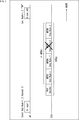
- FIG. 3 is a diagram schematically illustrating realization of high reliability by repeated transmission on the time axis.
- the direction from the left side to the right side in the figure is the time direction, and a predetermined direction is set between the base station AP shown in the upper time series and the terminal station STA shown in the lower time series. Wireless communication using the above frequency band is performed. Note that these relationships are the same in FIGS. 4 to 7 described later.
- the base station AP transmits a trigger frame (Trigger) to the terminal station STA.
- the trigger frame includes the sequence number (Seq. @ Num) of the frame (packet) to be transmitted and information indicating the number of repetitions (Repeat).
- the terminal station STA that has received the trigger frame transmitted from the base station AP transmits a frame (packet) with the number of repetitions specified in the trigger frame.
- the terminal station STA By repeatedly transmitting the same frame (packet) in this manner, for example, in FIG. 3, the terminal station STA fails to transmit the first MPDU # 2 (x in the figure). ), The subsequent transmission of the second MPDU # 2 has succeeded. As a result, since the base station AP can receive MPDU # 1 and MPDU # 2, the acknowledgment frame (Block @ ACK) is transmitted.
- a PPDU (PPDU: PLCP Protocol Data Unit, PLCP: Physical Layer Convergence Protocol) is a physical layer frame (PHY frame), and is an A-MPDU (MAC Protocol Data Unit Aggregation) in which a plurality of MPDUs are combined. And a physical layer header (PHY @ Header) is added.
- MPDU (MAC @ Protocol @ Data @ Unit) is a frame (MAC frame) of the MAC layer. Note that a frame including transmission data (for example, a PHY frame or a MAC frame) is also referred to as a first frame to distinguish it from other frames.
- the terminal station STA repeatedly transmits the same transmission data, so that even if the transmission of certain transmission data fails, if the transmission of the repeatedly transmitted other transmission data succeeds, the base station AP Can receive necessary transmission data, and as a result, the reliability of transmission can be improved.
- this technology proposes a technology that can realize highly reliable and low-latency communication in a wireless communication system such as a wireless LAN.
- a wireless communication system such as a wireless LAN.
- the allocation of new frequency bands has been pursuing wider bandwidths, and high reliability and low delay are required. It is possible to simultaneously satisfy two requirements of low delay.
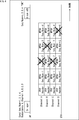
- FIG. 4 is a diagram schematically illustrating realization of high reliability and low delay by repeated transmission on the frequency axis. 4 to 7, uplink communication from the terminal station STA to the base station AP is assumed.
- the base station AP transmits an extended trigger frame (Trigger) to the terminal station STA.
- This extended trigger frame includes information such as redundancy information (Redundancy), frequency information (Channel), and order information (Seq. @ Num).
- the redundancy information is information relating to redundancy of transmission data transmitted by the terminal station STA or the base station AP.
- the redundancy information includes information on the number of repetitions (Repeat).
- the number of repetitions can be determined based on the characteristics of the terminal station STA (for example, the characteristics of network traffic) or the status of the terminal station STA (for example, the installation location).
- the number of repetitions is set to be larger than usual.
- the number of repetitions is set to be larger than usual.
- Frequency information is information on a frequency band (frequency resource) used for redundancy. Since the frequency information is information used for frequency multiplexing, it can be said that the frequency information is multiplex information related to multiplexing of transmission data.
- the base station AP observes the communication status (for example, which channel is used) of the other base station AP around the base station AP, and uses the channel whose vacancy is predicted. Channel to be determined.
- the base station AP sets channels A, B, C, D, which are vacant channels, based on the observation result of the communication status of the other base stations AP around the base station AP for a long term. Can be determined as the channel to be used.
- the base station AP makes four channels (channels A, ⁇ ⁇ ⁇ ⁇ B, C) each time the transmission data is made redundant (for example, repeatedly transmitted on the frequency axis) if the data amount is large. , D), while the data amount is small, fewer channels such as two channels (channels A, B) are used.
- the base station AP when the base station AP allocates four channels (channels A, B, C, D) to the terminal station STA as available channels, the terminal station STA has a certain channel (for example, , Channel C), the channel (eg, channel C) may be excluded from the available channels. That is, here, it can be said that the base station AP reflects the observation result on the terminal station STA side on the available channel.
- the sequence information includes the sequence number of the frame (packet). However, whether to include the order information (sequence number) in the extended trigger frame is optional.
- the extended trigger frame is an extension of the trigger frame defined by IEEE802.11ax, and is therefore referred to herein as an extended trigger frame.
- the structure of the extended trigger frame will be described later with reference to FIG. Further, the extended trigger frame is also referred to as a second frame to distinguish it from other frames.
- the terminal station STA receives the extended trigger frame transmitted from the base station AP, and multiplexes and transmits a redundant frame (packet) based on the information included in the extended trigger frame.
- Seq. ⁇ Num ⁇ ⁇ 1, ⁇ 2, ⁇ 3, ⁇ 4 ⁇ , Redundancy ⁇ 4, and Channels A, B, C, and D are designated as information included in the extended trigger frame.
- the station STA generates a PHY frame with the redundancy (Redundancy # 4) specified by the redundancy information, that is, the number of repetitions (Repeat # 4), for each channel (Channel # A, #B, #C, #D) specified by the frequency information.
- Send Send.
- MPDU # 3 MPDU of 3
- the terminal station STA transmits MPDU # 1, MPDU # 2, and MPDU # for each frequency band (for example, a channel frequency having a bandwidth of 20 MHz) corresponding to four channels (channels A, $ B, $ C, $ D).
- # 3 and MPDU # 4 are transmitted in order.
- the terminal station STA generates a PHY frame including MPDU # 1 to MPDU # 4 on the frequency axis based on the redundancy information (the number of repetitions) and the multiplexing information (frequency information) included in the extended trigger frame. It can be said that transmission is repeated four times (PHY frames # 1 to # 4 are transmitted simultaneously (multiplexed) in different frequency bands).
- the base station AP Since the transmission of MPDU # 1 has been successful on all the channels A, B, C, and D, the base station AP receives MPDU # 1 by communication using any channel frequency. Can be.
- the base station AP When the base station AP as a receiving station receives a PHY frame transmitted for each channel (channels A, ⁇ B, ⁇ C, ⁇ D) from the terminal station STA as a transmitting station, for example, Process. That is, the base station AP receives the PHY frame separately on each channel (channels A, B, C, and D), removes the error, and passes the normally received transmission data to the protocol upper layer. Alternatively, the received signals for each channel (channels A, B, C, D) are combined and subjected to signal processing (for example, decoding is attempted after adding the received signal power for each channel to obtain a higher power). )be able to.
- signal processing for example, decoding is attempted after adding the received signal power for each channel to obtain a higher power).
- the terminal station STA repeats the PHY frame including the transmission data on the frequency axis based on the redundancy information (number of repetitions) and the multiplexing information (frequency information) included in the extended trigger frame.
- the transmission on the frequency axis is performed repeatedly instead of the repetition transmission on the time axis as in the current system.
- burst interference may occur from another wireless LAN system or another network (BSS).
- BSS wireless LAN system
- the terminal station STA has interference with another wireless LAN system on a certain channel (channels B and C). Since it has occurred (“Interference” in the figure), it is determined that the channels B and ⁇ C where the interference has occurred cannot be used.
- the new method can transmit a PHY frame using the remaining channels A and D.
- the terminal station STA transmits MPDU # 1, MPDU # 2, MPDU # 3, and MPDU # for each of the frequency bands (channel frequencies) corresponding to the remaining channels A and #D where no interference occurs.
- # 4 are sequentially transmitted (PHY frames including MPDU # 1 to MPDU # 4 are repeatedly transmitted twice on the frequency axis).
- the new scheme can simultaneously satisfy two requirements of high reliability and low delay in a wireless communication system.
- the problem of bursty interference from other wireless LAN systems and other networks (BSS) has been a problem, but the adoption of a new method has reduced such interference. Is avoided, and the transmission data can be transmitted reliably.
- BSS wireless LAN systems and other networks
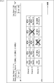
- FIG. 6 is a diagram schematically illustrating an example in which different bandwidths are allocated.
- the base station AP transmits an extended trigger frame to the terminal station STA.
- the extended trigger frame includes redundancy information (Redundancy), frequency information (Channel), and order information (Seq. @ Num). And other information.
- Seq. ⁇ Num ⁇ ⁇ 1, ⁇ 2, ⁇ 3, ⁇ 4 ⁇ , Redundancy ⁇ 3, and Channels A (20 MHz), B (20 MHz), and C (40 MHz), respectively. Is specified. However, the numbers in parentheses (unit: MHz) described for each channel indicate the channel bandwidth.
- the bandwidth of channel A and channel B is 20 MHz, but the bandwidth of channel C is 40 MHz, which is more than the bandwidth of channel A and channel B. It has a wide band. Therefore, the terminal station STA can selectively use a narrow-band channel (channel A, ⁇ B) and a wide-band channel (channel C) according to the characteristics of the transmission data (for example, the compression ratio of the transmission data).
- the terminal station STA that has received the extended trigger frame performs processing (for example, encoding or the like) on a single data stream, and performs compression processing corresponding to the bandwidth (for example, 20 MHz or 40 MHz) specified by the frequency information. To generate transmission data. Then, the terminal station STA transmits the PHY frame storing the transmission data corresponding to the low compression among the generated transmission data on the wideband channel C (bandwidth: 40 MHz), and transmits the transmission data corresponding to the high compression. Is transmitted over narrow-band channels A and B (bandwidth: 20 MHz).
- the terminal station STA Based on the information (redundancy information and frequency information) included in the extended trigger frame, the terminal station STA converts the transmission data compressed (redundant) at a compression rate corresponding to the bandwidth into a different bandwidth. It is multiplexed (frequency multiplexed) using a channel and transmitted to the base station AP.
- the terminal station STA transmits MPDU # 1, MPDU # 2, MPDU # 3, and MPDU # 4 sequentially using the narrow band channel A (bandwidth: 20 MHz). Also, on channel B (bandwidth: 20 MHz), MPDU # 1, MPDU # 2, MPDU # 3, and MPDU # 4 are transmitted sequentially in the same manner as channel A (bandwidth: 20MHz).
- HQ @ MPDU # 1, HQ @ MPDU # 2, HQ @ MPDU # 3, and HQ @ MPDU # 4 are sequentially transmitted using the wideband channel C (bandwidth: 40 MHz).
- HQ MPDU High Quality MPDU
- FIG. 6 an MPDU storing transmission data compatible with low compression (for example, data of an ultra-high quality image or the like) is described as HQ MPDU (High Quality MPDU), and the transmission data corresponding to high compression is described. (For example, data such as standard definition video).
- the terminal station STA transmits the PHY frame including the transmission data in a redundant manner on the frequency axis based on the information included in the extended trigger frame and transmits the PHY frame
- the different bandwidth (corresponding to the compression rate of the transmission data) Transmission is performed using a broadband or narrowband channel.
- the base station AP receiving the transmission data from the terminal station STA receives the HQ @ MPDU transmitted on the wideband channel C (bandwidth: 40 MHz) preferentially, and fails to receive the HQ @ MPDU. Only MPDUs transmitted on narrowband channels A and B (bandwidth: 20 MHz) are received.
- the terminal station STA transmits PHY frames # 1 and # 2 on narrow-band channels A and B (bandwidth: 20 MHz), respectively, and transmits PHY frames on wideband channel C (bandwidth: 40 MHz).
- the terminal station STA transmits PHY frames # 1 and # 2 on narrow-band channels A and B (bandwidth: 20 MHz), respectively, and transmits PHY frames on wideband channel C (bandwidth: 40 MHz).
- the terminal station STA transmits PHY frames # 1 and # 2 on narrow-band channels A and B (bandwidth: 20 MHz), respectively, and transmits PHY frames on wideband channel C (bandwidth: 40 MHz).
- the base station AP replaces the HQ MPDU # 2 with the HQ MPDU included in the PHY frames # 1 and # 2. Try to receive # 1.
- the base station AP receives transmission data (HQ MPDU) corresponding to low compression and transmission data (MPDU) corresponding to high compression while adaptively switching according to the reception state of transmission data. be able to.
- HQ MPDU transmission data
- MPDU transmission data
- a different bandwidth for example, 20 MHz
- a PHY frame storing transmission data corresponding to low compression can be transmitted on a wideband channel
- a PHY frame storing transmission data corresponding to high compression can be transmitted on a narrowband channel.
- transmission of ultra-high-quality video can be performed without delay.
- bandwidths there are two types of channel bandwidths, 20 MHz and 40 MHz.
- other bandwidths such as 60 MHz and 120 MHz may be used.
- another band such as a middle band may be allocated as a band between a wide band and a narrow band channel by using three or more types of bandwidths.
- FIG. 7 is a diagram schematically illustrating an example in which different frequency bands are used.
- the base station AP transmits an extended trigger frame to the terminal station STA.
- the extended trigger frame includes redundancy information (Redundancy), frequency information (Channel), and order information (Seq. @ Num).
- channel A and channel B use the 5 GHz band
- channel C uses the 60 GHz band and the available frequency band is Is different.
- the bandwidth of channel A and channel B is 20 MHz
- the bandwidth of channel C is 40 MHz, and the bandwidths are different.
- the terminal station STA transmits a PHY frame storing transmission data corresponding to low compression through a wideband channel C (bandwidth: 40 MHz).
- the PHY frame storing the transmission data corresponding to the high compression is transmitted on the narrow-band channels A and B (bandwidth: 20 MHz).
- the wideband channel C (bandwidth: 40 MHz) is in the 60 GHz band, but the narrowband channels A and B (bandwidth: 20 MHz) are in the 5 GHz band, and the available frequency band is Are different.
- the terminal station STA sequentially transmits MPDU # 1, MPDU # 2, MPDU # 3, and MPDU # 4 using the 5-GHz band channel A (bandwidth: 20 MHz). Also, in channel 5 of the 5 GHz band (bandwidth: 20 MHz), MPDU # 1, MPDU # 2, MPDU # 3, and MPDU # 4 are sequentially transmitted, as in channel A of the 5GHz band (bandwidth: 20 MHz). You. On the other hand, the terminal station STA sequentially transmits HQ @ MPDU # 1, HQ @ MPDU # 2, HQ @ MPDU # 3, and HQ @ MPDU # 4 using the channel C (bandwidth: 40 MHz) of the 60 GHz band.
- the terminal station STA transmits the PHY frame including the transmission data in a redundant manner on the frequency axis based on the information included in the extended trigger frame
- the terminal station STA transmits the PHY frame having a different bandwidth according to the compression rate of the transmission data. (20 MHz or 40 MHz) and using a different frequency band (5 GHz band or 60 GHz band).
- the base station AP preferentially receives the HQ MPDU transmitted on the channel C (bandwidth: 40 MHz) of the 60 GHz band, and Only when the reception of the MPDU fails, it is possible to receive the MPDU transmitted on the channels A and B (bandwidth: 20 MHz) of the 5 GHz band.
- a different bandwidth for example, 20 MHz
- different frequency bands for example, 5 GHz band and 60 GHz band
- a PHY frame storing transmission data corresponding to low compression can be transmitted on a wideband channel
- a PHY frame storing transmission data corresponding to high compression can be transmitted on a narrowband channel.
- transmission of ultra-high-quality video can be performed without delay.
- the description of the third example there has been described a case where there are two types of use frequency bands of 5 GHz band and 60 GHz band. However, for example, other use frequency bands such as a new frequency band (for example, 6 GHz band) are used. Alternatively, three or more types of frequency bands may be used. Further, in the description of the third example, as in the second example described above, a case has been described in which there are two types of channel bandwidths, 20 MHz and 40 MHz, but other bandwidths may be used. Alternatively, another band may be allocated by three or more types of bandwidths.
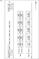
- FIG. 8 is a diagram schematically illustrating an example of a case where repetitive transmission on the frequency axis is performed during downlink communication.
- This advance notification frame (Redundancy @ Announcement @ Frame) includes at least multiplexing information such as redundancy information (Redundancy) and frequency information (Channel), like the above-described extended trigger frame.
- the advance notification frame may include order information (Seq. @ Num), similarly to the extended trigger frame.
- the base station AP as the transmitting station transmits a pre-notification frame to the terminal station STA as the receiving station in advance to determine the communication method to be performed (for example, how many times to repeat transmission on which channel). It can be said that it has declared.
- the base station AP which has notified the prior notification frame has MPDU # 1 and MPDU # 1 for each of the frequency bands (channel frequencies) corresponding to the two channels (Channels #A and #B) as previously notified in the frame.
- MPDU # 2, MPDU # 3, and MPDU # 4 are transmitted in order.
- the base station AP repeatedly transmits a PHY frame including MPDU # 1 to MPDU # 4 twice on the frequency axis based on the redundancy information and the frequency information notified by the advance notification frame ( PHY frames # 1 and # 2 are transmitted simultaneously in different frequency bands).
- the base station AP notifies the terminal station STA of the advance notification frame, so that even when performing downlink communication from the base station AP to the terminal station STA, repeated transmission on the frequency axis is performed. Can be performed, reliability can be improved, and requirements for low delay can be satisfied.
- the frequency information included in the advance notification frame includes, for example, information indicating a bandwidth and a used frequency band, in addition to information indicating a channel.
- the redundancy information, frequency information, and number information to be included in the advance notification frame are transmitted by the PHY header of a PHY frame repeatedly transmitted on the frequency axis. (PHY @ Header). In this case, the notification of the advance notification frame is unnecessary. Note that the prior notification frame is also referred to as a third frame to distinguish it from other frames.
- the terminal station STA In the case of communication performed by the terminal station STA without an instruction from the base station AP (uplink communication), the terminal station STA notifies the base station AP of a prior notification frame, and then transmits a PHY frame including transmission data. Will be sent. In this case as well, information such as redundancy information and frequency information may be stored in the PHY header.
- MIMO Multiple Input Multiple Output
- a plurality of antennas are used for both the base station AP and the terminal station STA.
- the signals are transmitted simultaneously using these antennas, but these antennas can be used to provide redundancy on the spatial axis. That is, here, the same transmission data (or transmission data having different compression ratios) is transmitted and received by different antennas, so that redundancy is provided on the space (antenna) axis.
- the redundancy information included in the extended trigger frame or the advance notification frame is not related to the number of repetitions on the frequency axis, but is related to the number of repetitions on the space (antenna) axis. Information may be included.
- the multiplexing information includes information (spatial information) related to a spatial stream (SS: Spatial @ Stream) instead of frequency information.
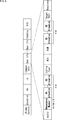
- FIG. 9 is a diagram illustrating an example of the format of an extended trigger frame.
- the extended trigger frame is obtained by extending a trigger frame defined by IEEE 802.11ax.
- the extended trigger frame includes Frame Control, Duration, RA, TA, Common Info, User Info, Padding, and FCS.
- ⁇ Frame ⁇ Control stores information about the type of the frame and the like.
- the Duration stores information on the length of this frame.
- RA Receiveiver @ Address
- TA Transmitter @ Address
- ⁇ Common ⁇ Info is a field for storing common information.
- User @ Info is a field for storing information for each user. Padding indicates padding for adjusting the frame length.
- FCS Fre @ Check @ Sequence
- the User @ Info field of the trigger frame is extended to store information such as redundancy information and multiplexing information.
- User @ Info includes AID12, Redundancy @ Number, RU @ Allocation, Coding @ Type, MCS, DCM, SS @ Allocation, Target @ RSSI, and Reserved.
- ⁇ Redundancy ⁇ Number stores information on the number of repetitions as redundancy. For example, in the first to third examples (FIGS. 4 to 7) of the above-described new scheme, since the repetition transmission on the frequency axis is performed at the time of uplink communication, the number of repetitions on the frequency axis is included in Redundancy @ Number. Information about (N) is stored. In the User @ Info field, N RU (Resource @ Unit) @Allocation fields are added in accordance with the number of repetitions (N) on the frequency axis stored in Redundancy @ Number, and frequency information is added to those fields. Is stored.
- N RU Resource @ Unit
- the Redundancy @ Number includes the spatial axis.
- Information about the number of repetitions (M) above or the number of repetitions (O) on the time axis can be stored.
- the number of repetitions (M) on the spatial axis stored in Redundancy @ Number that is, M SS (Spatial @ Stream) @Allocation fields corresponding to the number of antennas are added, and these are added. Spatial information is stored in the field.
- Redundancy when performing redundancy (repeated transmission) on the frequency axis, the space axis, or the time axis has been described.
- redundancy is not limited to single redundancy, but also includes multiple redundancy. It may be performed simultaneously in combination.
- Redundancy @ Number when performing redundancy (repeated transmission) on the frequency axis, the space axis, and the time axis at the same time, Redundancy @ Number includes the number of repetitions (N) on the frequency axis and the number of repetitions (M) on the space axis. , And information on the number of repetitions (O) on the time axis.
- FIG. 10 is a diagram illustrating an example of the format of the advance notification frame.
- the advance notification frame includes Frame Control, Duration, RA, TA, Common Info, Redundant Info, Padding, and FCS.
- Redundant Info includes Redundancy Number, RU Allocation, Coding Type, MCS, DCM, SS Allocation, and Reserved.
- ⁇ Redundancy ⁇ Number stores information on the number of repetitions as redundancy.
- N the number of repetitions (N) on the frequency axis is stored in Redundancy @ Number.
- N RU (Resource @ Unit) @Allocation fields store frequency information.
- Redundancy @ Number can store information about the number of repetitions (M) on the spatial axis or the number of repetitions (O) on the time axis. Spatial information is stored in M SS @ Allocation fields according to the number of repetitions (M) on the spatial axis stored in Redundancy @ Number.
- the prior notification frame (FIG. 10) can basically adopt the same configuration as the extended trigger frame (FIG. 9). While it is supposed that the transmission of the terminal station STA is induced, in the case of the advance notification frame (FIG. 10), since only one device (the base station AP) transmits after that, the ID information and the transmission are transmitted. Information such as power control (Target RSSI) can be omitted.
- Redundancy information and multiplexing information for example, frequency information and spatial information
- Information corresponding to the information stored in the Redundant @ Info field shown in FIG. 10 may be stored in the PHY header.
- the flowchart of FIG. 11 shows a flow of transmission / reception processing when uplink communication is performed with the terminal station STA serving as a transmitting station and the base station AP serving as a receiving station.
- steps S11 to S14 are executed by the control unit 101 of the base station AP (communication device 10), and the processes of steps S21 to S22 are performed by the control unit 101 of the terminal station STA (communication device 10). Is executed by
- step S11 the control unit 101 of the base station AP generates an extended trigger frame.
- the extended frame includes information such as redundancy information (information on the number of repetitions) and multiplexing information (frequency information).
- step S12 the control unit 101 of the base station AP controls the communication unit 103 to transmit the generated extended trigger frame to the terminal station STA.
- the extended trigger frame transmitted from the base station AP is received by the terminal station STA.
- step S21 the control unit 101 of the terminal station STA generates a PHY frame including transmission data based on the information included in the received extended trigger frame.
- step S22 the control unit 101 of the terminal station STA controls the communication unit 103 based on the information included in the received extended trigger frame, and transmits the generated PHY frame to the base station AP.
- the PHY frame is repeatedly transmitted on the frequency axis based on the redundancy information (information on the number of repetitions) and the multiplexing information (frequency information) included in the extended trigger frame.
- the PHY frame repeatedly transmitted on the frequency axis from the terminal station STA is received by the base station AP.
- step S13 the control unit 101 of the base station AP controls the data processing unit 102 and the communication unit 103 to process the received PHY frame. Processing data (transmission data) obtained by processing this PHY frame is passed to the protocol upper layer.
- step S14 the control section 101 of the base station AP controls the communication section 103 to transmit a confirmation frame (Block @ ACK) to the terminal station STA.
- the flowchart of FIG. 12 shows a flow of transmission / reception processing when downlink communication is performed with the base station AP serving as a transmitting station and the terminal station STA serving as a receiving station.
- steps S31 to S34 are executed by the control unit 101 of the base station AP (communication device 10), and the processes of steps S41 to S42 are performed by the control unit 101 of the terminal station STA (communication device 10). Is executed by
- step S31 the control unit 101 of the base station AP generates a prior notification frame.
- the advance notification frame includes information such as redundancy information (information on the number of repetitions) and multiplexing information (frequency information).
- step S32 the control unit 101 of the base station AP controls the communication unit 103 to transmit the generated advance notification frame to the terminal station STA.
- the advance notification frame transmitted from the base station AP is received by the terminal station STA. This allows the terminal station STA to prepare for repeated transmission on the frequency axis by the base station AP.
- step S33 the control unit 101 of the base station AP generates a PHY frame including transmission data based on information included in the generated advance notification frame.
- step S34 the control unit 101 of the base station AP controls the communication unit 103 based on the information included in the generated advance notification frame, and transmits the generated PHY frame to the terminal station STA.
- the PHY frame is repeatedly transmitted on the frequency axis based on the redundancy information (information on the number of repetitions) and the multiplexing information (frequency information) included in the advance notification frame.
- the PHY frame repeatedly transmitted on the frequency axis from the base station AP is received by the terminal station STA.
- step S41 the control unit 101 of the terminal station STA controls the data processing unit 102 and the communication unit 103 to process the received PHY frame. Processing data (transmission data) obtained by processing the PHY frame is passed to the protocol upper layer.
- step S42 the control section 101 of the terminal station STA controls the communication section 103 to transmit a confirmation frame (Block @ ACK) to the base station AP.
- a confirmation frame Block @ ACK
- the control unit 101 makes the transmission data transmitted by the base station AP or the terminal station STA redundant (for example, repeats transmission on the frequency axis).
- the function of this control may be included in the communication unit 103 configured as a communication device such as a communication module or a communication chip.
- FIGS. 13 and 14 are block diagrams illustrating examples of another configuration of an embodiment of a communication device (wireless communication device) to which the present technology is applied.
- the communication device 20 is different from the communication device 10 shown in FIG. 2 in that a communication unit 203 is provided instead of the communication unit 103.
- the communication unit 203 includes a communication control unit 201 in addition to the modulation / demodulation unit 111 to the amplifier unit 115.
- the communication control unit 201 has a control function for making the transmission data transmitted by the base station AP or the terminal station STA redundant, among the functions of the control unit 101 (FIG. 2).
- the control unit 101 in FIG. 13 has the same functions as those of the control unit 101 (FIG. 2) except for the control function for making the transmission data transmitted by the base station AP or the terminal station STA redundant. have.
- the communication device 30 is different from the communication device 10 shown in FIG. 2 in that the control unit 101 is removed and a communication unit 303 is provided instead of the communication unit 103.
- the communication unit 303 includes a control unit 301 in addition to the modulation / demodulation unit 111 to the amplifier unit 115.
- the control unit 301 has the same function as the control unit 101 (FIG. 2) (all functions including a control function for performing redundancy of transmission data transmitted by the base station AP or the terminal station STA described above). ing.
- the communication device 10, the communication device 20, and the communication device 30 may be configured as a part of a device (for example, a communication module, a communication chip, or the like) configuring the base station AP or the terminal station STA.
- the terminal station STA can be configured as an electronic device having a wireless communication function such as a smartphone, a tablet terminal, a mobile phone, a personal computer, a digital camera, a game machine, a television receiver, a wearable terminal, and a speaker device. it can.
- the term “communication” refers to communication in which wireless communication and wired communication are mixed, that is, wireless communication is performed in a certain section and wired communication is performed in another section. It may be. Further, communication from a certain device to another device may be performed by wired communication, and communication from another device to a certain device may be performed by wireless communication.
- the present technology can have the following configurations.
- a base station Redundancy information related to redundancy of transmission data transmitted by the terminal station or the base station, and multiplexing information related to multiplexing of the transmission data is generated
- a communication device comprising: a control unit that controls transmission of the generated redundancy information and the multiplexed information to the terminal station.
- the multiplexing information includes frequency information on a frequency band used when making a first frame including the transmission data redundant.
- the control unit performs control to receive the first frame multiplexed on a frequency axis transmitted from the terminal station.
- the redundancy information includes information on the number of repetitions when transmitting the first frame.
- the communication device including information on a bandwidth for each channel of a use frequency band that is an available frequency band.
- the transmission data is compressed at a compression rate corresponding to the bandwidth, The communication device according to (5), wherein the control unit performs control to receive the transmission data included in the first frame based on a priority according to the compression rate.
- the communication device (5) or (6), wherein the frequency information further includes information on the used frequency band for each channel.
- the communication device according to any one of (1) to (8), wherein the redundancy information and the multiplexing information are stored in a second frame for inducing transmission of a plurality of the terminal stations.
- the communication device according to any one of (1) to (8), wherein the redundancy information and the multiplexing information are stored in a header of a first frame including the transmission data.
- the control unit includes: Based on the state of communication of other base stations around the base station, to generate the frequency information, The communication device according to (4), wherein control is performed to generate the redundancy information including information on the number of repetitions based on information on the characteristics of the terminal station or the status of the terminal station.
- the redundancy information and the multiplexing information are stored in a third frame for notifying transmission to the specific terminal station in advance,
- the control unit includes: Prior to the first frame, transmitting the third frame to a specific terminal station;
- the redundancy information includes information on the number of repetitions on the spatial axis,
- the communication device according to any one of (1) to (12), wherein the multiplexing information includes information on a spatial stream.
- the communication device of the base station is Redundancy information related to redundancy of transmission data transmitted by the terminal station or the base station, and multiplexing information related to multiplexing of the transmission data is generated, A communication method for transmitting the generated redundancy information and the multiplexed information to the terminal station.
- a terminal station Received from the base station, redundancy information on redundancy of transmission data transmitted by the terminal station or the base station, and multiplexing information on multiplexing of the transmission data, Based on the received redundancy information and the multiplexing information, a frame containing the transmission data and a multiplexed first frame are transmitted to the base station or a multiplex transmitted from the base station.
- a communication device comprising: a control unit that performs control for receiving the first frame that has been converted.
- the multiplexing information includes frequency information on a frequency band used for redundancy, The communication device according to (15), wherein the control unit performs control to transmit the first frame multiplexed on a frequency axis to the base station.
- the redundancy information includes information on the number of repetitions when transmitting the first frame, The communication device according to (16), wherein the control unit performs control of repeatedly transmitting the first frame to the base station on a frequency axis.
- the frequency information includes information on a bandwidth for each channel of a use frequency band that is an available frequency band, The control unit according to (16), wherein the control unit performs control to transmit the first frame including the transmission data compressed at a compression rate corresponding to the bandwidth in a frequency band corresponding to the bandwidth.
- Communication device The frequency information further includes information on the used frequency band for each channel, The control unit transmits the first frame including the transmission data compressed at a compression rate corresponding to the bandwidth and the use frequency band in a frequency band corresponding to the bandwidth and the use frequency band.
- the communication device according to (18), which performs control.
- the communication device of the terminal station Received from the base station, redundancy information on redundancy of transmission data transmitted by the terminal station or the base station, and multiplexing information on multiplexing of the transmission data, Based on the received redundancy information and the multiplexing information, a frame containing the transmission data and a multiplexed first frame are transmitted to the base station or a multiplex transmitted from the base station.
- ⁇ 101 ⁇ control unit ⁇ 102 ⁇ data processing unit, ⁇ 103 ⁇ communication unit, ⁇ 104 ⁇ power supply unit, ⁇ 111 ⁇ modulation / demodulation unit, ⁇ 112 ⁇ signal processing unit, ⁇ 113 ⁇ channel estimation unit, ⁇ 114, 114-1 to 114-N ⁇ wireless interfaces Unit, ⁇ 115, 115-1 to 115-N ⁇ amplifier unit, ⁇ 116, 116-1 to 116-N ⁇ antenna, ⁇ 201 ⁇ communication control unit, ⁇ 203 ⁇ communication unit, ⁇ 301 ⁇ control unit, ⁇ 303 ⁇ communication unit, ⁇ AP ⁇ base station, ⁇ BSS ⁇ network, ⁇ STA ⁇ Terminal station
Landscapes
- Engineering & Computer Science (AREA)
- Computer Networks & Wireless Communication (AREA)
- Signal Processing (AREA)
- Mobile Radio Communication Systems (AREA)
- Detection And Prevention Of Errors In Transmission (AREA)
Abstract
Description
2.変形例
図1は、無線通信システムの構成の例を示す図である。
図2は、本技術を適用した通信装置(無線通信装置)の一実施の形態の構成の例を示すブロック図である。
図3は、時間軸上の繰り返し送信による高信頼性の実現を模式的に表した図である。
図4は、周波数軸上の繰り返し送信による高信頼性かつ低遅延性の実現を模式的に表した図である。なお、図4乃至図7においては、端末局STAから基地局APへのアップリンク通信を想定している。
図6は、異なる帯域幅の割り当てを行う場合の例を模式的に表した図である。
図7は、異なる周波数帯域を利用する場合の例を模式的に表した図である。
上述した図4乃至図7の説明では、端末局STAから基地局APへのアップリンク通信を想定した場合を説明したが、本技術を適用した新方式は、例えば、基地局APから端末局STAへのダウンリンク通信や、端末局STAが基地局APの指示なしで行う通信などに採用するようにしてもよい。
上述した説明では、冗長化の一例として、周波数軸上の繰り返し送信を行う場合を説明したが、新方式では、周波数軸上の繰り返し送信に限らず、例えば、空間軸上や時間軸上に冗長度を持たせるようにしてもよい。
図9は、拡張トリガフレームのフォーマットの例を示す図である。なお、この拡張トリガフレームは、IEEE802.11axで規定されるトリガフレームを拡張したものである。
図10は、事前通達フレームのフォーマットの例を示す図である。
次に、図11及び図12のフローチャートを参照して、基地局APと端末局STAの処理の流れを説明する。
上述した説明では、通信装置10(図2)において、制御部101(図2)が、基地局AP又は端末局STAが送信する送信データの冗長化を行う(例えば、周波数軸上で繰り返し送信を行う)ための制御を行うとして説明したが、この制御の機能は、通信モジュールや通信用チップ等の通信装置として構成される通信部103が有するようにしてもよい。
基地局であって、
端末局又は前記基地局が送信する送信データの冗長化に関する冗長度情報、及び前記送信データの多重化に関する多重化情報を生成し、
生成した前記冗長度情報及び前記多重化情報を、前記端末局に送信する
制御を行う制御部を備える
通信装置。
(2)
前記多重化情報は、前記送信データを含む第1のフレームの冗長化の際に利用する周波数帯域に関する周波数情報を含む
前記(1)に記載の通信装置。
(3)
前記制御部は、前記端末局から送信されてくる、周波数軸上で多重化された前記第1のフレームを受信する制御を行う
前記(2)に記載の通信装置。
(4)
前記冗長度情報は、前記第1のフレームを送信する際の繰り返し回数に関する情報を含む
前記(2)又は(3)に記載の通信装置。
(5)
前記周波数情報は、利用可能な周波数帯域である利用周波数帯のチャネルごとの帯域幅に関する情報を含む
前記(3)に記載の通信装置。
(6)
前記送信データは、前記帯域幅に対応した圧縮率で圧縮されており、
前記制御部は、前記圧縮率に応じた優先度に基づいて、前記第1のフレームに含まれる前記送信データを受信する制御を行う
前記(5)に記載の通信装置。
(7)
前記周波数情報は、前記チャネルごとの前記利用周波数帯に関する情報をさらに含む
前記(5)又は(6)に記載の通信装置。
(8)
前記送信データは、前記帯域幅及び前記利用周波数帯に対応した圧縮率で圧縮されており、
前記制御部は、前記圧縮率に応じた優先度に基づいて、前記第1のフレームに含まれる前記送信データを受信する制御を行う
前記(7)に記載の通信装置。
(9)
前記冗長度情報及び前記多重化情報は、複数の前記端末局の送信を誘起するための第2のフレームに格納される
前記(1)乃至(8)のいずれかに記載の通信装置。
(10)
前記冗長度情報及び前記多重化情報は、前記送信データを含む第1のフレームのヘッダに格納される
前記(1)乃至(8)のいずれかに記載の通信装置。
(11)
前記制御部は、
前記基地局の周囲の他の基地局の通信の状況に基づいて、前記周波数情報を生成し、
前記端末局の特性、又は前記端末局の状況に関する情報に基づいて、前記繰り返し回数に関する情報を含む前記冗長度情報を生成する
制御を行う
前記(4)に記載の通信装置。
(12)
前記冗長度情報及び前記多重化情報は、特定の前記端末局に対する送信を事前に通達するための第3のフレームに格納され、
前記制御部は、
前記第1のフレームに先行して、前記第3のフレームを、特定の前記端末局に送信し、
生成した前記冗長度情報及び前記多重化情報に基づいて、周波数軸上で多重化した前記第1のフレームを、特定の前記端末局に送信する
制御を行う
前記(2)に記載の通信装置。
(13)
前記冗長度情報は、空間軸上の繰り返し回数に関する情報を含み、
前記多重化情報は、空間ストリームに関する情報を含む
前記(1)乃至(12)のいずれかに記載の通信装置。
(14)
基地局の通信装置が、
端末局又は前記基地局が送信する送信データの冗長化に関する冗長度情報、及び前記送信データの多重化に関する多重化情報を生成し、
生成した前記冗長度情報及び前記多重化情報を、前記端末局に送信する
通信方法。
(15)
端末局であって、
基地局から送信されてくる、前記端末局又は前記基地局が送信する送信データの冗長化に関する冗長度情報、及び前記送信データの多重化に関する多重化情報を受信し、
受信した前記冗長度情報及び前記多重化情報に基づいて、前記送信データを含むフレームであって多重化した第1のフレームを前記基地局に送信するか、又は前記基地局から送信されてくる多重化された前記第1のフレームを受信する
制御を行う制御部を備える
通信装置。
(16)
前記多重化情報は、冗長化の際に利用する周波数帯域に関する周波数情報を含み、
前記制御部は、周波数軸上で多重化された前記第1のフレームを、前記基地局に送信する制御を行う
前記(15)に記載の通信装置。
(17)
前記冗長度情報は、前記第1のフレームを送信する際の繰り返し回数に関する情報を含み、
前記制御部は、前記第1のフレームを、周波数軸上で繰り返して記基地局に送信する制御を行う
前記(16)に記載の通信装置。
(18)
前記周波数情報は、利用可能な周波数帯域である利用周波数帯のチャネルごとの帯域幅に関する情報を含み、
前記制御部は、前記帯域幅に対応した圧縮率で圧縮された前記送信データを含む前記第1のフレームを、前記帯域幅に対応した周波数帯域で送信する制御を行う
前記(16)に記載の通信装置。
(19)
前記周波数情報は、前記チャネルごとの前記利用周波数帯に関する情報をさらに含み、
前記制御部は、前記帯域幅及び前記利用周波数帯に対応した圧縮率で圧縮された前記送信データを含む前記第1のフレームを、前記帯域幅及び前記利用周波数帯に対応した周波数帯域で送信する制御を行う
前記(18)に記載の通信装置。
(20)
端末局の通信装置が、
基地局から送信されてくる、前記端末局又は前記基地局が送信する送信データの冗長化に関する冗長度情報、及び前記送信データの多重化に関する多重化情報を受信し、
受信した前記冗長度情報及び前記多重化情報に基づいて、前記送信データを含むフレームであって多重化した第1のフレームを前記基地局に送信するか、又は前記基地局から送信されてくる多重化された前記第1のフレームを受信する
通信方法。
Claims (20)
- 基地局であって、
端末局又は前記基地局が送信する送信データの冗長化に関する冗長度情報、及び前記送信データの多重化に関する多重化情報を生成し、
生成した前記冗長度情報及び前記多重化情報を、前記端末局に送信する
制御を行う制御部を備える
通信装置。 - 前記多重化情報は、前記送信データを含む第1のフレームの冗長化の際に利用する周波数帯域に関する周波数情報を含む
請求項1に記載の通信装置。 - 前記制御部は、前記端末局から送信されてくる、周波数軸上で多重化された前記第1のフレームを受信する制御を行う
請求項2に記載の通信装置。 - 前記冗長度情報は、前記第1のフレームを送信する際の繰り返し回数に関する情報を含む
請求項2に記載の通信装置。 - 前記周波数情報は、利用可能な周波数帯域である利用周波数帯のチャネルごとの帯域幅に関する情報を含む
請求項3に記載の通信装置。 - 前記送信データは、前記帯域幅に対応した圧縮率で圧縮されており、
前記制御部は、前記圧縮率に応じた優先度に基づいて、前記第1のフレームに含まれる前記送信データを受信する制御を行う
請求項5に記載の通信装置。 - 前記周波数情報は、前記チャネルごとの前記利用周波数帯に関する情報をさらに含む
請求項5に記載の通信装置。 - 前記送信データは、前記帯域幅及び前記利用周波数帯に対応した圧縮率で圧縮されており、
前記制御部は、前記圧縮率に応じた優先度に基づいて、前記第1のフレームに含まれる前記送信データを受信する制御を行う
請求項7に記載の通信装置。 - 前記冗長度情報及び前記多重化情報は、複数の前記端末局の送信を誘起するための第2のフレームに格納される
請求項1に記載の通信装置。 - 前記冗長度情報及び前記多重化情報は、前記送信データを含む第1のフレームのヘッダに格納される
請求項1に記載の通信装置。 - 前記制御部は、
前記基地局の周囲の他の基地局の通信の状況に基づいて、前記周波数情報を生成し、
前記端末局の特性、又は前記端末局の状況に関する情報に基づいて、前記繰り返し回数に関する情報を含む前記冗長度情報を生成する
制御を行う
請求項4に記載の通信装置。 - 前記冗長度情報及び前記多重化情報は、特定の前記端末局に対する送信を事前に通達するための第3のフレームに格納され、
前記制御部は、
前記第1のフレームに先行して、前記第3のフレームを、特定の前記端末局に送信し、
生成した前記冗長度情報及び前記多重化情報に基づいて、周波数軸上で多重化した前記第1のフレームを、特定の前記端末局に送信する
制御を行う
請求項2に記載の通信装置。 - 前記冗長度情報は、空間軸上の繰り返し回数に関する情報を含み、
前記多重化情報は、空間ストリームに関する情報を含む
請求項1に記載の通信装置。 - 基地局の通信装置が、
端末局又は前記基地局が送信する送信データの冗長化に関する冗長度情報、及び前記送信データの多重化に関する多重化情報を生成し、
生成した前記冗長度情報及び前記多重化情報を、前記端末局に送信する
通信方法。 - 端末局であって、
基地局から送信されてくる、前記端末局又は前記基地局が送信する送信データの冗長化に関する冗長度情報、及び前記送信データの多重化に関する多重化情報を受信し、
受信した前記冗長度情報及び前記多重化情報に基づいて、前記送信データを含むフレームであって多重化した第1のフレームを前記基地局に送信するか、又は前記基地局から送信されてくる多重化された前記第1のフレームを受信する
制御を行う制御部を備える
通信装置。 - 前記多重化情報は、冗長化の際に利用する周波数帯域に関する周波数情報を含み、
前記制御部は、周波数軸上で多重化された前記第1のフレームを、前記基地局に送信する制御を行う
請求項15に記載の通信装置。 - 前記冗長度情報は、前記第1のフレームを送信する際の繰り返し回数に関する情報を含み、
前記制御部は、前記第1のフレームを、周波数軸上で繰り返して記基地局に送信する制御を行う
請求項16に記載の通信装置。 - 前記周波数情報は、利用可能な周波数帯域である利用周波数帯のチャネルごとの帯域幅に関する情報を含み、
前記制御部は、前記帯域幅に対応した圧縮率で圧縮された前記送信データを含む前記第1のフレームを、前記帯域幅に対応した周波数帯域で送信する制御を行う
請求項16に記載の通信装置。 - 前記周波数情報は、前記チャネルごとの前記利用周波数帯に関する情報をさらに含み、
前記制御部は、前記帯域幅及び前記利用周波数帯に対応した圧縮率で圧縮された前記送信データを含む前記第1のフレームを、前記帯域幅及び前記利用周波数帯に対応した周波数帯域で送信する制御を行う
請求項18に記載の通信装置。 - 端末局の通信装置が、
基地局から送信されてくる、前記端末局又は前記基地局が送信する送信データの冗長化に関する冗長度情報、及び前記送信データの多重化に関する多重化情報を受信し、
受信した前記冗長度情報及び前記多重化情報に基づいて、前記送信データを含むフレームであって多重化した第1のフレームを前記基地局に送信するか、又は前記基地局から送信されてくる多重化された前記第1のフレームを受信する
通信方法。
Priority Applications (4)
| Application Number | Priority Date | Filing Date | Title |
|---|---|---|---|
| CN201980044425.3A CN112369067B (zh) | 2018-07-06 | 2019-06-21 | 通信设备和通信方法 |
| BR112020026990-5A BR112020026990A2 (pt) | 2018-07-06 | 2019-06-21 | Dispositivos de comunicação que constituem uma estação base e uma estação terminal, e, método de comunicação |
| US17/250,300 US11956089B2 (en) | 2018-07-06 | 2019-06-21 | Communication device and communication method |
| AU2019299028A AU2019299028B2 (en) | 2018-07-06 | 2019-06-21 | Communication device and communication method |
Applications Claiming Priority (2)
| Application Number | Priority Date | Filing Date | Title |
|---|---|---|---|
| JP2018-129069 | 2018-07-06 | ||
| JP2018129069A JP2021166321A (ja) | 2018-07-06 | 2018-07-06 | 通信装置、及び通信方法 |
Publications (1)
| Publication Number | Publication Date |
|---|---|
| WO2020008908A1 true WO2020008908A1 (ja) | 2020-01-09 |
Family
ID=69060247
Family Applications (1)
| Application Number | Title | Priority Date | Filing Date |
|---|---|---|---|
| PCT/JP2019/024641 Ceased WO2020008908A1 (ja) | 2018-07-06 | 2019-06-21 | 通信装置、及び通信方法 |
Country Status (6)
| Country | Link |
|---|---|
| US (1) | US11956089B2 (ja) |
| JP (1) | JP2021166321A (ja) |
| CN (1) | CN112369067B (ja) |
| AU (1) | AU2019299028B2 (ja) |
| BR (1) | BR112020026990A2 (ja) |
| WO (1) | WO2020008908A1 (ja) |
Cited By (2)
| Publication number | Priority date | Publication date | Assignee | Title |
|---|---|---|---|---|
| CN113067782A (zh) * | 2020-08-12 | 2021-07-02 | 浙江华云信息科技有限公司 | 基于冗余系统的高可靠性电能量采集传输系统 |
| WO2022210090A1 (ja) * | 2021-04-01 | 2022-10-06 | シャープ株式会社 | アクセスポイント装置、ステーション装置および通信方法 |
Families Citing this family (1)
| Publication number | Priority date | Publication date | Assignee | Title |
|---|---|---|---|---|
| CN113428193B (zh) * | 2021-06-29 | 2023-10-20 | 通号城市轨道交通技术有限公司 | 一种基于rfid处理站场图状态的方法及装置 |
Citations (5)
| Publication number | Priority date | Publication date | Assignee | Title |
|---|---|---|---|---|
| JP2005039775A (ja) * | 2003-07-15 | 2005-02-10 | Samsung Electronics Co Ltd | モバイルアドホックネットワーク環境での効率的なデータ送受信のためのネットワーク装置及びデータ転送方法 |
| WO2011043392A1 (ja) * | 2009-10-06 | 2011-04-14 | 株式会社エヌ・ティ・ティ・ドコモ | 基地局装置及びユーザ装置 |
| JP2013197996A (ja) * | 2012-03-21 | 2013-09-30 | Advanced Telecommunication Research Institute International | 通信装置、通信方法、及びプログラム |
| JP2015513258A (ja) * | 2012-02-23 | 2015-04-30 | クゥアルコム・インコーポレイテッドQualcomm Incorporated | マルチソース多入力多出力通信のためのシステムおよび方法 |
| WO2017115609A1 (ja) * | 2015-12-28 | 2017-07-06 | ソニー株式会社 | 装置及び方法 |
Family Cites Families (6)
| Publication number | Priority date | Publication date | Assignee | Title |
|---|---|---|---|---|
| KR100873117B1 (ko) * | 2001-09-10 | 2008-12-09 | 엘지전자 주식회사 | 하이브리드 자동 재송 요구 방식을 이용한 패킷 재전송 방법 |
| JP4755137B2 (ja) * | 2007-05-01 | 2011-08-24 | 株式会社エヌ・ティ・ティ・ドコモ | 基地局装置及び通信制御方法 |
| CN103416017B (zh) | 2010-11-12 | 2016-11-16 | 交互数字专利控股公司 | 用于执行信道聚合和媒介访问控制重传的方法和设备 |
| JP6331967B2 (ja) * | 2014-10-27 | 2018-05-30 | ソニー株式会社 | 通信装置および通信方法 |
| CN108496408B (zh) * | 2016-01-26 | 2023-10-20 | 株式会社Ntt都科摩 | 基站及发送方法 |
| US10764946B2 (en) * | 2017-05-09 | 2020-09-01 | Vivint Wireless, Inc. | Autonomous mesh topology |
-
2018
- 2018-07-06 JP JP2018129069A patent/JP2021166321A/ja active Pending
-
2019
- 2019-06-21 WO PCT/JP2019/024641 patent/WO2020008908A1/ja not_active Ceased
- 2019-06-21 AU AU2019299028A patent/AU2019299028B2/en not_active Ceased
- 2019-06-21 CN CN201980044425.3A patent/CN112369067B/zh active Active
- 2019-06-21 US US17/250,300 patent/US11956089B2/en active Active
- 2019-06-21 BR BR112020026990-5A patent/BR112020026990A2/pt unknown
Patent Citations (5)
| Publication number | Priority date | Publication date | Assignee | Title |
|---|---|---|---|---|
| JP2005039775A (ja) * | 2003-07-15 | 2005-02-10 | Samsung Electronics Co Ltd | モバイルアドホックネットワーク環境での効率的なデータ送受信のためのネットワーク装置及びデータ転送方法 |
| WO2011043392A1 (ja) * | 2009-10-06 | 2011-04-14 | 株式会社エヌ・ティ・ティ・ドコモ | 基地局装置及びユーザ装置 |
| JP2015513258A (ja) * | 2012-02-23 | 2015-04-30 | クゥアルコム・インコーポレイテッドQualcomm Incorporated | マルチソース多入力多出力通信のためのシステムおよび方法 |
| JP2013197996A (ja) * | 2012-03-21 | 2013-09-30 | Advanced Telecommunication Research Institute International | 通信装置、通信方法、及びプログラム |
| WO2017115609A1 (ja) * | 2015-12-28 | 2017-07-06 | ソニー株式会社 | 装置及び方法 |
Cited By (2)
| Publication number | Priority date | Publication date | Assignee | Title |
|---|---|---|---|---|
| CN113067782A (zh) * | 2020-08-12 | 2021-07-02 | 浙江华云信息科技有限公司 | 基于冗余系统的高可靠性电能量采集传输系统 |
| WO2022210090A1 (ja) * | 2021-04-01 | 2022-10-06 | シャープ株式会社 | アクセスポイント装置、ステーション装置および通信方法 |
Also Published As
| Publication number | Publication date |
|---|---|
| US20210273754A1 (en) | 2021-09-02 |
| AU2019299028B2 (en) | 2022-03-17 |
| CN112369067A (zh) | 2021-02-12 |
| BR112020026990A2 (pt) | 2021-03-30 |
| JP2021166321A (ja) | 2021-10-14 |
| CN112369067B (zh) | 2024-08-09 |
| AU2019299028A1 (en) | 2021-02-04 |
| US11956089B2 (en) | 2024-04-09 |
Similar Documents
| Publication | Publication Date | Title |
|---|---|---|
| US11799523B2 (en) | Group acknowledgement for multiple user communication in a wireless local area network | |
| US10764874B2 (en) | Trigger frame format for orthogonal frequency division multiple access (OFDMA) communication | |
| US8730930B2 (en) | Polling using B-ACK for occasional back-channel traffic in VoWIFI applications | |
| CN113595682B (zh) | 在无线lan系统中发送或接收信号的方法及其设备 | |
| JP6715204B2 (ja) | 無線通信装置および無線通信方法 | |
| US11522646B2 (en) | Electronic apparatus and method | |
| US12542578B2 (en) | Multi-access point communication devices and methods for coordinated join transmission with reduced backhaul requirements | |
| CN106605373A (zh) | 无线通信用集成电路、无线通信终端以及无线通信方法 | |
| US12278773B2 (en) | System and method for aggregating communications links | |
| CN115943682A (zh) | 终端及通信方法 | |
| WO2020008908A1 (ja) | 通信装置、及び通信方法 | |
| US20250097853A1 (en) | Communication device | |
| JP2022160878A (ja) | 通信装置、通信装置の制御方法、およびプログラム | |
| US20100118816A1 (en) | Apparatus and method for transmitting data in wireless communication system | |
| CN113597000B (zh) | 传输无线局域网分组结构ppdu的方法、相关设备以及系统 | |
| US11943324B2 (en) | Electronic device supporting variable compression rate on basis of radio link condition | |
| TWI809772B (zh) | 多播廣播服務同時傳輸方法和使用者設備 |
Legal Events
| Date | Code | Title | Description |
|---|---|---|---|
| 121 | Ep: the epo has been informed by wipo that ep was designated in this application |
Ref document number: 19831570 Country of ref document: EP Kind code of ref document: A1 |
|
| NENP | Non-entry into the national phase |
Ref country code: DE |
|
| REG | Reference to national code |
Ref country code: BR Ref legal event code: B01A Ref document number: 112020026990 Country of ref document: BR |
|
| ENP | Entry into the national phase |
Ref document number: 2019299028 Country of ref document: AU Date of ref document: 20190621 Kind code of ref document: A |
|
| ENP | Entry into the national phase |
Ref document number: 112020026990 Country of ref document: BR Kind code of ref document: A2 Effective date: 20201230 |
|
| 122 | Ep: pct application non-entry in european phase |
Ref document number: 19831570 Country of ref document: EP Kind code of ref document: A1 |
|
| NENP | Non-entry into the national phase |
Ref country code: JP |