WO2020008916A1 - Dispositif à cycle frigorifique et son procédé de commande - Google Patents
Dispositif à cycle frigorifique et son procédé de commande Download PDFInfo
- Publication number
- WO2020008916A1 WO2020008916A1 PCT/JP2019/024744 JP2019024744W WO2020008916A1 WO 2020008916 A1 WO2020008916 A1 WO 2020008916A1 JP 2019024744 W JP2019024744 W JP 2019024744W WO 2020008916 A1 WO2020008916 A1 WO 2020008916A1
- Authority
- WO
- WIPO (PCT)
- Prior art keywords
- refrigerant
- pressure
- compression mechanism
- refrigeration cycle
- temperature
- Prior art date
- Legal status (The legal status is an assumption and is not a legal conclusion. Google has not performed a legal analysis and makes no representation as to the accuracy of the status listed.)
- Ceased
Links
Images


Classifications
-
- F—MECHANICAL ENGINEERING; LIGHTING; HEATING; WEAPONS; BLASTING
- F25—REFRIGERATION OR COOLING; COMBINED HEATING AND REFRIGERATION SYSTEMS; HEAT PUMP SYSTEMS; MANUFACTURE OR STORAGE OF ICE; LIQUEFACTION SOLIDIFICATION OF GASES
- F25B—REFRIGERATION MACHINES, PLANTS OR SYSTEMS; COMBINED HEATING AND REFRIGERATION SYSTEMS; HEAT PUMP SYSTEMS
- F25B47/00—Arrangements for preventing or removing deposits or corrosion, not provided for in another subclass
- F25B47/006—Arrangements for preventing or removing deposits or corrosion, not provided for in another subclass for preventing frost
-
- F—MECHANICAL ENGINEERING; LIGHTING; HEATING; WEAPONS; BLASTING
- F25—REFRIGERATION OR COOLING; COMBINED HEATING AND REFRIGERATION SYSTEMS; HEAT PUMP SYSTEMS; MANUFACTURE OR STORAGE OF ICE; LIQUEFACTION SOLIDIFICATION OF GASES
- F25B—REFRIGERATION MACHINES, PLANTS OR SYSTEMS; COMBINED HEATING AND REFRIGERATION SYSTEMS; HEAT PUMP SYSTEMS
- F25B1/00—Compression machines, plants or systems with non-reversible cycle
- F25B1/10—Compression machines, plants or systems with non-reversible cycle with multi-stage compression
-
- F—MECHANICAL ENGINEERING; LIGHTING; HEATING; WEAPONS; BLASTING
- F25—REFRIGERATION OR COOLING; COMBINED HEATING AND REFRIGERATION SYSTEMS; HEAT PUMP SYSTEMS; MANUFACTURE OR STORAGE OF ICE; LIQUEFACTION SOLIDIFICATION OF GASES
- F25B—REFRIGERATION MACHINES, PLANTS OR SYSTEMS; COMBINED HEATING AND REFRIGERATION SYSTEMS; HEAT PUMP SYSTEMS
- F25B13/00—Compression machines, plants or systems, with reversible cycle
-
- F—MECHANICAL ENGINEERING; LIGHTING; HEATING; WEAPONS; BLASTING
- F25—REFRIGERATION OR COOLING; COMBINED HEATING AND REFRIGERATION SYSTEMS; HEAT PUMP SYSTEMS; MANUFACTURE OR STORAGE OF ICE; LIQUEFACTION SOLIDIFICATION OF GASES
- F25B—REFRIGERATION MACHINES, PLANTS OR SYSTEMS; COMBINED HEATING AND REFRIGERATION SYSTEMS; HEAT PUMP SYSTEMS
- F25B49/00—Arrangement or mounting of control or safety devices
- F25B49/02—Arrangement or mounting of control or safety devices for compression type machines, plants or systems
- F25B49/022—Compressor control arrangements
-
- F—MECHANICAL ENGINEERING; LIGHTING; HEATING; WEAPONS; BLASTING
- F25—REFRIGERATION OR COOLING; COMBINED HEATING AND REFRIGERATION SYSTEMS; HEAT PUMP SYSTEMS; MANUFACTURE OR STORAGE OF ICE; LIQUEFACTION SOLIDIFICATION OF GASES
- F25B—REFRIGERATION MACHINES, PLANTS OR SYSTEMS; COMBINED HEATING AND REFRIGERATION SYSTEMS; HEAT PUMP SYSTEMS
- F25B2313/00—Compression machines, plants or systems with reversible cycle not otherwise provided for
- F25B2313/031—Sensor arrangements
- F25B2313/0314—Temperature sensors near the indoor heat exchanger
-
- F—MECHANICAL ENGINEERING; LIGHTING; HEATING; WEAPONS; BLASTING
- F25—REFRIGERATION OR COOLING; COMBINED HEATING AND REFRIGERATION SYSTEMS; HEAT PUMP SYSTEMS; MANUFACTURE OR STORAGE OF ICE; LIQUEFACTION SOLIDIFICATION OF GASES
- F25B—REFRIGERATION MACHINES, PLANTS OR SYSTEMS; COMBINED HEATING AND REFRIGERATION SYSTEMS; HEAT PUMP SYSTEMS
- F25B2313/00—Compression machines, plants or systems with reversible cycle not otherwise provided for
- F25B2313/031—Sensor arrangements
- F25B2313/0315—Temperature sensors near the outdoor heat exchanger
-
- F—MECHANICAL ENGINEERING; LIGHTING; HEATING; WEAPONS; BLASTING
- F25—REFRIGERATION OR COOLING; COMBINED HEATING AND REFRIGERATION SYSTEMS; HEAT PUMP SYSTEMS; MANUFACTURE OR STORAGE OF ICE; LIQUEFACTION SOLIDIFICATION OF GASES
- F25B—REFRIGERATION MACHINES, PLANTS OR SYSTEMS; COMBINED HEATING AND REFRIGERATION SYSTEMS; HEAT PUMP SYSTEMS
- F25B2400/00—Component parts or details not otherwise provided for in this subclass
- F25B2400/13—Economisers
-
- F—MECHANICAL ENGINEERING; LIGHTING; HEATING; WEAPONS; BLASTING
- F25—REFRIGERATION OR COOLING; COMBINED HEATING AND REFRIGERATION SYSTEMS; HEAT PUMP SYSTEMS; MANUFACTURE OR STORAGE OF ICE; LIQUEFACTION SOLIDIFICATION OF GASES
- F25B—REFRIGERATION MACHINES, PLANTS OR SYSTEMS; COMBINED HEATING AND REFRIGERATION SYSTEMS; HEAT PUMP SYSTEMS
- F25B2600/00—Control issues
- F25B2600/02—Compressor control
- F25B2600/022—Compressor control for multi-stage operation
-
- F—MECHANICAL ENGINEERING; LIGHTING; HEATING; WEAPONS; BLASTING
- F25—REFRIGERATION OR COOLING; COMBINED HEATING AND REFRIGERATION SYSTEMS; HEAT PUMP SYSTEMS; MANUFACTURE OR STORAGE OF ICE; LIQUEFACTION SOLIDIFICATION OF GASES
- F25B—REFRIGERATION MACHINES, PLANTS OR SYSTEMS; COMBINED HEATING AND REFRIGERATION SYSTEMS; HEAT PUMP SYSTEMS
- F25B2600/00—Control issues
- F25B2600/02—Compressor control
- F25B2600/025—Compressor control by controlling speed
- F25B2600/0253—Compressor control by controlling speed with variable speed
-
- F—MECHANICAL ENGINEERING; LIGHTING; HEATING; WEAPONS; BLASTING
- F25—REFRIGERATION OR COOLING; COMBINED HEATING AND REFRIGERATION SYSTEMS; HEAT PUMP SYSTEMS; MANUFACTURE OR STORAGE OF ICE; LIQUEFACTION SOLIDIFICATION OF GASES
- F25B—REFRIGERATION MACHINES, PLANTS OR SYSTEMS; COMBINED HEATING AND REFRIGERATION SYSTEMS; HEAT PUMP SYSTEMS
- F25B2600/00—Control issues
- F25B2600/25—Control of valves
- F25B2600/2509—Economiser valves
-
- F—MECHANICAL ENGINEERING; LIGHTING; HEATING; WEAPONS; BLASTING
- F25—REFRIGERATION OR COOLING; COMBINED HEATING AND REFRIGERATION SYSTEMS; HEAT PUMP SYSTEMS; MANUFACTURE OR STORAGE OF ICE; LIQUEFACTION SOLIDIFICATION OF GASES
- F25B—REFRIGERATION MACHINES, PLANTS OR SYSTEMS; COMBINED HEATING AND REFRIGERATION SYSTEMS; HEAT PUMP SYSTEMS
- F25B2700/00—Sensing or detecting of parameters; Sensors therefor
- F25B2700/19—Pressures
- F25B2700/193—Pressures of the compressor
- F25B2700/1933—Suction pressures
-
- F—MECHANICAL ENGINEERING; LIGHTING; HEATING; WEAPONS; BLASTING
- F25—REFRIGERATION OR COOLING; COMBINED HEATING AND REFRIGERATION SYSTEMS; HEAT PUMP SYSTEMS; MANUFACTURE OR STORAGE OF ICE; LIQUEFACTION SOLIDIFICATION OF GASES
- F25B—REFRIGERATION MACHINES, PLANTS OR SYSTEMS; COMBINED HEATING AND REFRIGERATION SYSTEMS; HEAT PUMP SYSTEMS
- F25B2700/00—Sensing or detecting of parameters; Sensors therefor
- F25B2700/21—Temperatures
- F25B2700/2117—Temperatures of an evaporator
- F25B2700/21174—Temperatures of an evaporator of the refrigerant at the inlet of the evaporator
-
- Y—GENERAL TAGGING OF NEW TECHNOLOGICAL DEVELOPMENTS; GENERAL TAGGING OF CROSS-SECTIONAL TECHNOLOGIES SPANNING OVER SEVERAL SECTIONS OF THE IPC; TECHNICAL SUBJECTS COVERED BY FORMER USPC CROSS-REFERENCE ART COLLECTIONS [XRACs] AND DIGESTS
- Y02—TECHNOLOGIES OR APPLICATIONS FOR MITIGATION OR ADAPTATION AGAINST CLIMATE CHANGE
- Y02B—CLIMATE CHANGE MITIGATION TECHNOLOGIES RELATED TO BUILDINGS, e.g. HOUSING, HOUSE APPLIANCES OR RELATED END-USER APPLICATIONS
- Y02B30/00—Energy efficient heating, ventilation or air conditioning [HVAC]
- Y02B30/70—Efficient control or regulation technologies, e.g. for control of refrigerant flow, motor or heating
Definitions
- the present invention relates to a refrigeration cycle device provided with a refrigerant circuit through which a refrigerant flows, and a method for controlling the refrigeration cycle device.
- a representative low GWP refrigerant is HFO-1234yf, which has been developed as an alternative refrigerant to HFC-134a.
- HFO-1234yf the pressure obtained in the refrigerant circuit tends to be low. Therefore, a low GWP refrigerant such as HFO-1234yf may be used in combination with a refrigerant such as R32 to supplement the pressure.
- FIG. 6A shows the evaporation process using a single refrigerant with a broken line.
- FIG. 6B shows the evaporation process using a non-azeotropic refrigerant by a broken line.
- the dashed-dotted lines show isotherms where the temperature of the refrigerant is equal.
- 6 (a) and 6 (b) the evaporator inlet is shown by a circle.
- frost is formed on the evaporator during a heating operation such as heating, even when the outside air temperature is higher than when a single refrigerant is used.
- the first expansion valve located upstream of the evaporator is separated from the first expansion valve during the evaporation process.
- Two expansion valves are arranged.
- the present invention relates to a refrigerant circuit using a non-azeotropic refrigerant, and provides a refrigeration cycle device capable of suppressing a decrease in the inlet temperature of an evaporator due to a temperature slip and a control method thereof, while suppressing costs. With the goal.
- the refrigeration cycle device of the present invention includes a refrigerant circuit through which a non-azeotropic refrigerant flows, and a control unit that controls elements constituting the refrigerant circuit.
- the refrigerant circuit is connected in series, a first compression mechanism and a second compression mechanism that compress the refrigerant, a first heat exchanger that exchanges heat between the heat source and the refrigerant, and a first pressure reducing unit that reduces the pressure of the refrigerant.
- An intermediate pressure supply unit that supplies the intermediate pressure to the second compression mechanism.
- the control unit may control the first compression mechanism based on an index indicating an evaporator inlet temperature, which is a temperature at a start end of the evaporation process by one of the first heat exchanger and the second heat exchanger. And controlling the operating speed of the second compression mechanism or controlling the operating speed of the first compression mechanism and the second compression mechanism when set to a predetermined mode for suppressing a decrease in the evaporator inlet temperature. It is characterized.
- the refrigerant circuit includes a second pressure reducing section that reduces the pressure of a part of the refrigerant that has undergone the condensation process, and a primary pressure that is higher than the intermediate pressure, and the second pressure reducing section reduces the pressure. And an internal heat exchanger that cools by exchanging heat with the secondary refrigerant.
- the intermediate pressure supply unit preferably supplies the secondary refrigerant that has passed through the internal heat exchanger to the second compression mechanism.
- the refrigerant circuit further includes a second pressure reducing unit that stores the refrigerant that has undergone the condensation process and reduces the pressure.
- the refrigeration cycle apparatus can perform a heating operation of heating a heat load by the refrigerant circuit.
- the first heat exchanger functions as an evaporator
- the second heat exchanger It preferably functions as a condenser.
- control unit increases the target value of the intermediate pressure and controls the operation speed of the first compression mechanism so that the intermediate pressure becomes the target value.
- control unit has a storage unit that stores the index and the target value in association with each other over a predetermined variable range of the index.
- the refrigerant circuit includes a temperature sensor that detects an evaporator inlet temperature, an air temperature sensor that detects the temperature of the atmosphere near the evaporator, and a pressure that detects the pressure of the refrigerant at the start end of the evaporation process. It is preferable that the sensor further includes at least one of sensors, and the indicator is determined using at least one of a temperature detected by the temperature sensor, a temperature detected by the air temperature sensor, and a pressure detected by the pressure sensor.
- the present invention is also a circuit in which a non-azeotropic refrigerant flows, wherein the first compression mechanism, the second compression mechanism, and the second compression mechanism have an intermediate pressure in which the pressure of the refrigerant that has undergone the condensation process is reduced.
- An intermediate pressure supply unit for supplying a refrigerant, and a method for controlling a refrigeration cycle apparatus including a refrigerant circuit having an evaporator inlet temperature which is a temperature at a start end of an evaporation process.
- the present invention provides a circuit through which a non-azeotropic refrigerant flows, wherein the first compression mechanism, the second compression mechanism, and the second compression mechanism have an intermediate pressure in which the pressure of the refrigerant that has undergone the condensation process is reduced.
- a method for controlling a refrigeration cycle apparatus including a refrigerant circuit having an intermediate pressure supply unit for supplying a refrigerant, the method comprising: suppressing a decrease in an evaporator inlet temperature which is a temperature at a start end of an evaporation process.
- the control step is characterized by including a control step of controlling the operating speeds of the first compression mechanism and the second compression mechanism when is set to.
- control step it is preferable to increase the target value of the intermediate pressure and control the operating speed of the first compression mechanism so that the intermediate pressure becomes the target value.
- the target value of the intermediate pressure is set to a value corresponding to the variable index, and the operation speed of the first compression mechanism is controlled so that the intermediate pressure becomes the target value. preferable.
- the refrigerant circuit provided in the refrigeration cycle device of the present invention includes a two-stage compressor, and has the same configuration as an existing refrigerant circuit of the same type without adding a component to the refrigerant circuit of the same type that performs injection at an intermediate pressure. can do. Further, according to the present invention, as will be described in detail later, when it is necessary to suppress a decrease in the evaporator inlet temperature, increasing the intermediate pressure and controlling the rotation speed of the first compressor affects the refrigerating capacity. , The injection amount can be reduced and the evaporator inlet temperature can be raised.
- FIG. 3 is a ph diagram according to the embodiment of the present invention.
- (A) shows the refrigeration cycle in the case without the control of evaporator inlet temperature suppression by broken lines.
- B) shows the refrigeration cycle without the control of the evaporator inlet temperature suppression and the refrigeration cycle with the control of the evaporator inlet temperature suppression by solid lines. It is a figure which shows the procedure of the evaporator inlet temperature fall suppression control which concerns on embodiment of this invention.
- (A) is a schematic diagram for demonstrating the effect of frost formation suppression by control of evaporator inlet temperature fall suppression.
- (B) is a diagram showing a correspondence relationship between an index indicating the evaporator inlet temperature and a target value of the intermediate pressure. It is a figure which shows typically the refrigeration cycle apparatus which concerns on the modification of this invention. The “evaporation process” and “condensation process” are described based on the heating operation.
- (A) is a figure which shows the refrigerant
- (b) is a figure which shows the refrigerant
- the refrigeration cycle apparatus 1 illustrated in FIG. 1 includes a refrigerant circuit 10 through which a non-azeotropic refrigerant flows, and a control unit 20 that controls the refrigerant circuit 10.
- the refrigeration cycle device 1 can be configured as various devices including a refrigerant circuit through which a refrigerant flows, for example, an air conditioner, a refrigerator, a water heater, a heat pump, and the like.
- the non-azeotropic refrigerant is a mixture of two or more refrigerants having different boiling points.
- a mixture of HFO-1234yf and R32 corresponds to the non-azeotropic refrigerant.
- examples of other non-azeotropic refrigerants include a refrigerant in which HFO-1234ze and R32 are mixed, a refrigerant in which hydrocarbons and R32 are mixed, and the like.
- a non-azeotropic refrigerant (hereinafter simply “refrigerant”) is sealed in the refrigerant circuit 10 at a predetermined mixing ratio and circulates through the refrigerant circuit 10.
- control of the control unit 20 of the present embodiment it is possible to suppress a decrease in the refrigerant temperature at the inlet of the evaporator. Therefore, during the heating operation of the refrigeration cycle apparatus 1, it is possible to suppress the occurrence of frost on the evaporator.
- the refrigerant circuit 10 (FIG. 1) includes a low-stage compressor 11 (first compression mechanism), a high-stage compressor 12 (second compression mechanism), and two heat exchangers 13 and 14 (first heat exchanger and It has a second heat exchanger), a first decompression unit 15, an intermediate pressure injection unit 30 (intermediate pressure supply unit) including a second decompression unit 31, and a four-way valve 16.
- the refrigerant circuit 10 can perform both the cooling operation and the heating operation by switching the direction of the flow of the refrigerant by the four-way valve 16. In FIG. 1, the direction in which the refrigerant flows through the refrigerant circuit 10 during the heating operation is indicated by arrows.
- the refrigeration cycle apparatus 1 cools or heats a heat load using outside air as a heat source by a refrigeration cycle including a process of compressing, condensing, expanding by reducing pressure, and evaporating a refrigerant flowing through a refrigerant circuit 10.
- the refrigeration cycle apparatus 1 may have a variable capacity according to the fluctuating heat load, or may have a constant capacity regardless of the heat load.
- the refrigerant circuit 10 includes a plurality of stages of compressors 11 and 12 and an intermediate pressure injection unit 30 that supplies a refrigerant having an intermediate pressure Pm between the compressors 11 and 12. Therefore, according to the refrigerant circuit 10, the compression efficiency can be ensured and the temperature of the refrigerant discharged from the compressor can be suppressed as compared with the case where the same refrigeration capacity is obtained by one-stage compression.
- the configuration of the refrigerant circuit 10 corresponds to a typical configuration of the same type of refrigerant circuit including the low-stage compressor 11 and the high-stage compressor 12 and the intermediate-pressure injection unit 30.
- the refrigerant circuit 10 of the present embodiment can be composed of only components provided in the same type of refrigerant circuit.
- Each of the low-stage compressor 11 and the high-stage compressor 12 compresses a refrigerant by rotating a scroll or a rotary piston or reciprocating a vane by a power source such as an electric motor.
- the low-stage compressor 11 includes an appropriate compression mechanism (not shown) such as a scroll compression mechanism, for example, and a housing 111 that houses the compression mechanism.
- the low-stage compressor 11 may include a plurality of compression mechanisms inside the housing 111.
- the high-stage compressor 12 also includes an appropriate compression mechanism (not shown) such as a scroll compression mechanism, for example, and a housing 121 that houses the compression mechanism.
- the high-stage compressor 12 may include a plurality of compression mechanisms in the housing 121.
- Both the low-stage compressor 11 and the high-stage compressor 12 are configured such that the operation speed of the compression mechanism is variable based on a command from the control unit 20.
- a drive current generated by a drive device provided in the compressor is applied to the motor based on a command indicating a rotation speed of the scroll, so that the scroll Is controlled.
- the operating speed is referred to as a rotational speed, assuming a compression mechanism that compresses the refrigerant by a rotational operation.
- the refrigerant compressed by the low-stage compressor 11 is drawn into the high-stage compressor 12 and compressed to a higher pressure.
- a discharge section 11B for discharging the refrigerant from the low-stage compressor 11 and an introduction section 12A for introducing the refrigerant to the high-stage compressor 12 are connected by a pipe 120.
- the first heat exchanger 13 exchanges heat between the outside air, which is a heat source, and the refrigerant.
- the first heat exchanger 13 functions as a condenser during the cooling operation, and functions as an evaporator during the heating operation.
- the second heat exchanger 14 exchanges heat between air, water, or the like, which is a heat load, and the refrigerant.
- the second heat exchanger 14 functions as an evaporator during the cooling operation, and functions as a condenser during the heating operation.
- Each of the first and second heat exchangers 13 and 14 in FIG. 1 is additionally provided with a process (evaporation process / condensation process) performed during the heating operation.
- the first pressure reducing unit 15 reduces the pressure of the refrigerant that has undergone the condensation process.
- an expansion valve, a capillary tube, or the like can be used as the first pressure reducing unit 15.
- the intermediate-pressure injection unit 30 supplies the second compressor 12 with the intermediate-pressure Pm refrigerant, the pressure of which has been reduced with respect to the refrigerant that has undergone the condensation process, in both the heating operation and the cooling operation.
- the intermediate pressure injection unit 30 of the present embodiment includes a second pressure reducing unit 31 and an internal heat exchanger 32.
- the second decompression unit 31 reduces the pressure of a part of the refrigerant that has undergone the condensation process and supplies the reduced pressure to the internal heat exchanger 32.
- the refrigerant that has undergone a condensation process in the first heat exchanger 13 or the second heat exchanger 14 passes through the second decompression unit 31 and the internal heat exchanger 32 and directs the injection flow path 33 toward the second compressor 12. Flows.
- the second pressure reducing section 31 an expansion valve, a combination of a capillary tube and a valve, or the like can be used.
- the second pressure reducing unit 31 is typically an expansion valve, and the throttle amount is controlled according to a command from the control unit 20.
- the internal heat exchanger 32 heats the primary refrigerant flowing toward the first pressure reducing unit 15 without flowing into the second pressure reducing unit 31 and the secondary refrigerant whose pressure is reduced by the second pressure reducing unit 31.
- the primary refrigerant is cooled by the replacement.
- the pressure of the secondary refrigerant, the pressure of which has been reduced by the second pressure reducing section 31, is lower than that of the primary refrigerant flowing through the internal heat exchanger 32, and the temperature is also lower. Therefore, in the internal heat exchanger 32, the primary refrigerant flowing through the path indicated by the solid line and the secondary refrigerant flowing through the path indicated by the broken line exchange heat based on the temperature difference.
- the internal heat exchanger 32 basically, heat exchange is performed between the primary refrigerant, which is a high-pressure liquid, and the secondary refrigerant, which is a low-pressure gas. Then, the secondary refrigerant further gasified by the endothermic heat from the primary refrigerant in the internal heat exchanger 32 is supplied to the second compressor 12.
- the amount (injection amount) of the refrigerant supplied to the second compressor 12 via the second pressure reducing unit 31 and the internal heat exchanger 32 is controlled by controlling the second pressure reducing unit 31 and flowing into the second pressure reducing unit 31. Can be adjusted by adjusting the flow rate. Since the efficiency of heat exchange of the internal heat exchanger 32 depends on the temperature difference between the primary refrigerant and the secondary refrigerant, the control unit 20 throttles the second pressure reducing unit 31 when the temperature of the secondary refrigerant increases, Reduce injection volume.
- the second pressure reducing unit 31 may be completely closed.
- control unit 20 is also configured to prevent the secondary refrigerant from being supplied to the high-stage compressor 12 without being sufficiently gasified in the internal heat exchanger 32,
- the second pressure reducing unit 31 is throttled to reduce the injection amount.
- the temperature of the secondary refrigerant increases as the pressure (intermediate pressure Pm) of the refrigerant supplied to the high-stage compressor 12 increases. Therefore, as the intermediate pressure Pm detected by the pressure sensor 18 located between the low-stage compressor 11 and the high-stage compressor 12 is higher, the control unit 20 narrows the second pressure reducing unit 31 to reduce the injection amount. .
- the amount of the refrigerant flowing from the condenser to the first decompression unit 15 increases by the amount of the decrease in the injection amount.
- the intermediate-pressure injection unit 30 of the present embodiment injects a medium-pressure refrigerant into a pipe 120 that connects the low-stage compressor 11 and the high-stage compressor 12, so that the refrigerant is discharged together with the refrigerant discharged from the low-stage compressor 11.
- the refrigerant having the intermediate pressure Pm is supplied into the housing 121 of the high-stage compressor 12.
- the intermediate pressure injection unit 30 may be configured to supply the intermediate pressure refrigerant to the second compressor 12 separately from the refrigerant discharged from the low stage compressor 11.
- FIGS. 2A and 2B show a refrigeration cycle using the refrigerant circuit 10.
- FIG. 2A shows a refrigeration cycle Y ⁇ b> 1 when the control unit 20 does not perform a control for suppressing a decrease in the evaporator inlet temperature described later by a broken line.
- FIG. 2B shows a refrigeration cycle Y2 by a solid line in a case where the control unit 20 performs control to suppress a decrease in the evaporator inlet temperature described later, in addition to the refrigeration cycle Y1.
- the compression process of the refrigeration cycle Y1 includes a compression process a1 by the low-stage compressor 11 and a compression process a2 by the high-stage compressor 12.
- the pressure at the boundary between the compression process a1 and the compression process a2 corresponds to the intermediate pressure Pm supplied to the high-stage compressor 12 by the intermediate pressure injection unit 30.
- the refrigerant compressed by the low-stage compressor 11 and the high-stage compressor 12 passes through a condensation process b1 by a condenser (for example, the second heat exchanger 14), and is absorbed in the internal heat exchanger 32 by a partially decompressed refrigerant. Being condensed further. Then, in the example shown in FIG. 2A, supercooling is performed (b2). When the condensing process including the condensing process b1 and the condensing process b2 by the internal heat exchanger 32 is completed, the pressure of the refrigerant is reduced by the first pressure reducing unit 15 (c2).
- the pressure reduction process of the refrigeration cycle Y1 includes a pressure reduction process c1 by the second pressure reduction unit 31 and a pressure reduction process c2 by the first pressure reduction unit 15.
- the refrigerant that has passed through the pressure reduction step c2 reaches the compression step a1 via the evaporation step d by the evaporator (for example, the first heat exchanger 13).
- the control unit 20 uses the measured values such as temperature and pressure detected by various sensors and the predetermined values such as temperature and pressure to reduce the pressure in the refrigerant circuits 10 and 31. And controls the operation of various valves and elements such as the compressors 11 and 12.
- the control unit 20 is applied to a refrigerant circuit 10 including a low-stage compressor 11 and a high-stage compressor 12 connected in series, and an intermediate-pressure injection unit 30 that supplies a refrigerant of an intermediate pressure Pm to the high-stage compressor 12. Is done.
- the control unit 20 that controls the refrigerant circuit 10 sends a command to the second pressure reducing unit 31 that is an expansion valve or the like according to a change in heat load or an operating condition, so that the intermediate-pressure injection unit 30 uses the high-stage compressor.
- the amount (injection amount) of the refrigerant supplied to 12 can be adjusted.
- Such control may be the same as control by a typical control unit used in a refrigerant circuit that supplies a refrigerant at the intermediate pressure Pm to the high-stage compressor 12.
- the control unit 20 of the present embodiment controls the low-stage evaporator based on an index indicating the evaporator inlet temperature.
- the rotation speed of each compression mechanism of the compressor 11 and the high-stage compressor 12 is controlled.
- the “evaporator inlet temperature” corresponds to the temperature of the refrigerant at the start end of the evaporation process by one of the first heat exchanger 13 and the second heat exchanger 14.
- a high pressure Ph which is a pressure in the condenser (corresponding to a pressure of the refrigerant discharged from the high-stage compressor 12) and a low pressure Pl which is a pressure in the evaporator (low-stage (Corresponding to the pressure of the refrigerant sucked into the compressor 11).
- an intermediate pressure Pm is set in addition to the high pressure Ph and the low pressure Pl. This intermediate pressure Pm is typically set at or near the center value between the high pressure Ph and the low pressure Pl.
- the control unit 20 performs feedback control on the rotation speed of the high-stage compressor 12 based on the high pressure Ph, and performs feedback control on the rotation speed of the low-stage compressor 11 based on the intermediate pressure Pm.
- the rotation speed of the low-stage compressor 11 and the rotation speed of the high-stage compressor 12 are balanced at a predetermined ratio under normal conditions by the control of the control unit 20.
- control is performed while performing basic control of the refrigerant circuit 10 such as control for adjusting the injection amount by the second pressure reducing unit 31 and rotation speed control of the compressors 11 and 12 based on the high pressure Ph and the intermediate pressure Pm.
- the unit 20 increases the rotation speed of the low-stage compressor 11 based on the index X indicating the evaporator inlet temperature when it is necessary to suppress a decrease in the evaporator inlet temperature. Then, as described later, the rotation speed of the high-stage compressor 12 decreases. That is, as a result of increasing the rotation speed of the low-stage compressor 11, the rotation speed ratio of the compressors 11, 12 changes from normal.
- the control of the rotation speeds of the low-stage compressor 11 and the high-stage compressor 12, which is performed to suppress a decrease in the evaporator inlet temperature, is performed so that the performance of the refrigeration cycle apparatus 1 is not affected. It is preferable that the control is performed prior to the control such as 31. This will be described later.
- the control unit 20 uses the index X indicating the temperature of the inlet of the evaporator.
- the index X is determined using the temperature sensor 17 that detects the evaporator inlet temperature.
- the temperature sensor 17 is attached near the inlet of the first heat exchanger 13 that functions as an evaporator during the heating operation. For the purpose of suppressing the formation of frost on the evaporator during the heating operation, it is sufficient that the temperature sensor 17 is attached near the inlet of the first heat exchanger 13.
- the index X can be determined using a temperature detected by a temperature sensor (air temperature sensor) that detects the temperature of the atmosphere (outside air) near the evaporator.
- a pressure sensor for detecting the pressure of the refrigerant at the evaporator inlet can be attached near the evaporator inlet.
- the index X can also be determined using the pressure detected by the pressure sensor. Since the pressure sensor directly detects the temperature of the refrigerant inside the evaporator, the pressure sensor usually evaporates more than when using a temperature sensor that is attached to the outside of the evaporator and detects the refrigerant temperature via an evaporator member. An index X that appropriately indicates the refrigerant temperature at the inlet of the vessel can be determined. Note that the index X may be determined using two or more of the temperature sensor 17, the temperature sensor, and the pressure sensor.
- the temperature and dryness of the refrigerant at the outlet of the evaporator can be used to determine the index X.
- the index X can be determined in advance based on a test performed by operating the refrigeration cycle apparatus 1, a simulation, or the like.
- the index X may be stored in the storage unit 21 provided in the control unit 20, and the index X may be read from the storage unit 21 and used for control.
- the control unit 20 can be configured as a computer including the calculation unit 22 and the storage unit 21.
- the control by the control unit 20 can be realized by creating a computer program corresponding to the control by the control unit 20 and executing the computer program.
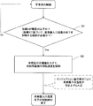
- Control of refrigeration cycle device With reference to FIG. 3 and FIG. 2, the control of the control unit 20 when the evaporator inlet temperature decreases will be described. This control corresponds to control for suppressing frost formation on the evaporator during the heating operation.
- the control unit 20 determines the necessity of suppressing a decrease in the evaporator inlet temperature based on the index X indicating the evaporator inlet temperature (determination step S1). For example, assuming that the temperature detected by the temperature sensor 17 is the index X, if the temperature detected by the temperature sensor 17 is equal to or less than the threshold value, it is determined that it is necessary to suppress a decrease in the evaporator inlet temperature. You. If it is determined in determination step S1 that it is necessary to suppress a decrease in the evaporator inlet temperature (Yes in step S1), the rotation speed of the low-stage compressor 11 is increased (rotation speed control step S2).
- the temperature measurement by the temperature sensor 17 is repeated during a certain period, and the temperature measurement value becomes a predetermined value. If the number of times exceeds the reference, the process may proceed to step S2 or lower.
- the control unit 20 increases the target value of the intermediate pressure Pm and performs feedback control of the rotation speed of the low-stage compressor 11 so that the intermediate pressure Pm becomes the target value.
- the rotation speed of the compressor 11 is increased. This is for the reasons described below.
- the second pressure reducing unit 31 Since the temperature of the refrigerant increases with an increase in the intermediate pressure Pm, the second pressure reducing unit 31 is throttled as described above, and the injection amount decreases. As the injection amount decreases, the enthalpy at the evaporator inlet increases, so that the evaporator inlet temperature is raised. Here, when the injection amount decreases, the flow rate of the refrigerant flowing through the evaporator increases. At this time, since the low pressure Pl (the suction pressure of the low-stage compressor 11) does not change, the rotation speed of the low-stage compressor 11 is increased in order to increase the amount of circulating refrigerant.
- the low pressure Pl the suction pressure of the low-stage compressor 11
- step S2 the rotation speed of the high-stage compressor 12 is feedback-controlled by the control unit 20 so that the high pressure Ph becomes constant, so that the rotation speed of the high-stage compressor 12 decreases.
- the refrigeration cycle by the refrigerant circuit 10 changes from the state shown by the broken line (Y1) to the state (Y2) shown by the solid line, as shown in FIG. 2B.
- the control unit 20 increases the target value of the intermediate pressure Pm, and The rotation speed of the stage compressor 11 is increased (step S2). Then, the intermediate pressure Pm increases, and as described above, the low pressure Pl and the high pressure Ph do not change, and the rotation speed of the high-stage compressor 12 decreases.
- the injection amount IN (expressed by the thickness of the white arrow in FIG. 2B). Is reduced).
- the enthalpy at the outlet of the internal heat exchanger 32 increases because the flow rate of the secondary refrigerant decreases.
- the enthalpy at the evaporator inlet is also increased, so that the evaporator inlet temperature T is raised (black arrow in FIG. 2B).
- the evaporator inlet temperature can be raised in comparison with the case where the evaporator inlet temperature decrease suppression control indicated by the broken line in FIG. 2B is not performed.
- the control described above can be performed during both the heating operation and the cooling operation.
- the evaporator inlet temperature is raised, so that the occurrence of frost on the evaporator (first heat exchanger 13) can be suppressed during the heating operation.
- FIG. 4A shows a difference in the frost formation temperature range of the evaporator depending on whether or not the control for suppressing the decrease in the evaporator inlet temperature is performed.
- frost is formed while the outside air temperature is relatively high.
- the outside air temperature at which frost occurs can be reduced.
- the control may be returned to the normal control when, for example, the index X exceeds a predetermined threshold.
- the threshold value at this time can be set to be larger than the threshold value at the time of shifting from the control in the normal state to the control for suppressing the decrease in the evaporator inlet temperature.
- the control may be returned to the normal control regardless of the index X after a predetermined time has elapsed since the shift to the control for suppressing the decrease in the evaporator inlet temperature.
- the control unit 20 instead of controlling the rotation speeds of the low-stage compressor 11 and the high-stage compressor 12 on the basis of the index X, the control unit 20 enters a predetermined mode for suppressing a decrease in the evaporator inlet temperature.
- the same control may be performed. That is, when the control unit 20 is set to such a mode, the control unit 20 increases the target value of the intermediate pressure Pm and controls the rotation speed of the low-stage compressor 11 so that the intermediate pressure Pm becomes the target value. I do. At this time, the rotation speed of the low-stage compressor 11 increases, and the rotation speed of the high-stage compressor 12 decreases. Then, a decrease in the injection amount can suppress a decrease in the evaporator inlet temperature.
- the refrigerant circuit 10 of the refrigeration cycle apparatus 1 according to the present embodiment is different from the existing refrigerant circuit of the same type without adding components to the same type of refrigerant circuit having the two-stage compressors 11 and 12 and the intermediate pressure injection unit 30. It can be configured similarly. There is no need to split the evaporator and add an expansion valve. Also, the control unit 20 of the refrigeration cycle apparatus 1 performs the basic control of the control unit applied to the same type of refrigerant circuit as the refrigerant circuit 10 by using the intermediate pressure Pm when it is necessary to suppress a decrease in the evaporator inlet temperature.
- the existing refrigerant circuit 10 can be used, thereby suppressing the cost and suppressing the decrease in the inlet temperature of the evaporator due to the temperature slip caused by the non-azeotropic refrigerant. Frost formation on the evaporator can be suppressed.
- the rotational speeds of the compressors 11 and 12 are controlled prior to a decrease in the injection amount by the control of the second pressure reducing unit 31.
- the rotation speed of the high-stage compressor 12 is controlled so as to maintain the high pressure Ph. Therefore, the required predetermined performance can be ensured without affecting the performance of the refrigeration cycle device 1. Further, the temperature of the refrigerant sucked into the high-stage compressor 12 can be suppressed to ensure reliability.
- the target value of the intermediate pressure it can be increased to a constant pressure or to a variable pressure determined according to a predetermined condition. Alternatively, the pressure may be increased to a fixed or variable increment of the current intermediate pressure target.
- FIG. 4B shows a correspondence relationship between the index X and the intermediate pressure target value when the index X is the temperature detected by the temperature sensor 17 that detects the evaporator inlet temperature.
- the required refrigeration capacity is constant.
- the intermediate pressure target value is variable depending on the index X, the In the example, the intermediate pressure target value is set so as to increase as the index X decreases. As the intermediate pressure target value increases, the intermediate pressure Pm further increases, and the injection amount further decreases accordingly. Therefore, by controlling the rotation speeds of the compressors 11 and 12 while giving the intermediate pressure target value corresponding to the index X to the control unit 20, the refrigeration cycle apparatus 1 can be surely prevented from lowering the evaporator inlet temperature. Can be operated efficiently. It is preferable that the index X and the intermediate pressure target value be stored in the storage unit 21 of the control unit 20 in association with each other over a predetermined variable range of the index X.
- control unit 20 supplies the intermediate pressure target value corresponding to the changing index X to the compressor 11. , 12 are preferably controlled.
- a refrigeration cycle apparatus 2 according to a modification of the present invention will be described with reference to FIG.
- the description will focus on matters that differ from the above-described embodiment.
- the same components as those in the above-described embodiment are denoted by the same reference numerals.
- a receiver 34 (second pressure reducing unit) is used as a mechanism for supplying the intermediate-pressure refrigerant to the high-stage compressor 12.
- the receiver 34 is incorporated in the refrigerant circuit 10 instead of the above-described second decompression unit 31 and the internal heat exchanger 32.
- the receiver 34 receives, stores, and decompresses the high-pressure liquid refrigerant that has undergone the condensation process.
- the pressure of the refrigerant flowing into the receiver 34 decreases inside the receiver 34.
- the refrigerant separates into liquid and gas due to the difference in density between the liquid phase and the gas phase of the refrigerant.
- the gas refrigerant inside the receiver 34 is supplied to the high-stage compressor 12.
- the intermediate pressure target value is increased, and the rotation speed of the low-stage compressor 11 is controlled (increased) so that the intermediate pressure Pm becomes the intermediate pressure target value.
- the intermediate pressure Pm increases, the amount of refrigerant supplied to the high-stage compressor 12 from the receiver 34 based on the pressure difference between the inside of the receiver 34 and the intermediate pressure Pm, that is, the injection amount decreases. Accordingly, a decrease in the evaporator inlet temperature can be suppressed.
- the refrigeration cycle device of the present invention is not limited to the one used for both heating and cooling of the heat load, and may be configured for heating only or cooling only. In this case, the four-way valve 16 is not required.
- a low-stage first compression mechanism and a high-stage second compression mechanism are arranged inside a housing of one compressor, and a first compression mechanism and a second compression mechanism are interposed between the first compression mechanism and the second compression mechanism.
- Intermediate pressure refrigerant may be supplied.
- the control unit 20 can be applied to a refrigerant circuit including such a compressor.
- the present invention can also be applied to a refrigerant circuit including three or more compressors connected in series and configured to supply a medium-pressure refrigerant to at least one compressor.
Landscapes
- Engineering & Computer Science (AREA)
- Physics & Mathematics (AREA)
- Mechanical Engineering (AREA)
- Thermal Sciences (AREA)
- General Engineering & Computer Science (AREA)
- Compression-Type Refrigeration Machines With Reversible Cycles (AREA)
- Devices That Are Associated With Refrigeration Equipment (AREA)
Abstract
Priority Applications (5)
| Application Number | Priority Date | Filing Date | Title |
|---|---|---|---|
| KR1020217000320A KR102460317B1 (ko) | 2018-07-06 | 2019-06-21 | 냉동 사이클 장치 및 그 제어 방법 |
| CN201980044287.9A CN112368523B (zh) | 2018-07-06 | 2019-06-21 | 冷冻循环装置以及其控制方法 |
| JP2020528798A JP7078724B2 (ja) | 2018-07-06 | 2019-06-21 | 冷凍サイクル装置およびその制御方法 |
| ES19830394T ES3037436T3 (en) | 2018-07-06 | 2019-06-21 | Refrigeration cycle device and method for controlling same |
| EP19830394.3A EP3819556B1 (fr) | 2018-07-06 | 2019-06-21 | Dispositif à cycle frigorifique et son procédé de commande |
Applications Claiming Priority (2)
| Application Number | Priority Date | Filing Date | Title |
|---|---|---|---|
| JP2018-128686 | 2018-07-06 | ||
| JP2018128686 | 2018-07-06 |
Publications (1)
| Publication Number | Publication Date |
|---|---|
| WO2020008916A1 true WO2020008916A1 (fr) | 2020-01-09 |
Family
ID=69060246
Family Applications (1)
| Application Number | Title | Priority Date | Filing Date |
|---|---|---|---|
| PCT/JP2019/024744 Ceased WO2020008916A1 (fr) | 2018-07-06 | 2019-06-21 | Dispositif à cycle frigorifique et son procédé de commande |
Country Status (6)
| Country | Link |
|---|---|
| EP (1) | EP3819556B1 (fr) |
| JP (1) | JP7078724B2 (fr) |
| KR (1) | KR102460317B1 (fr) |
| CN (1) | CN112368523B (fr) |
| ES (1) | ES3037436T3 (fr) |
| WO (1) | WO2020008916A1 (fr) |
Cited By (1)
| Publication number | Priority date | Publication date | Assignee | Title |
|---|---|---|---|---|
| WO2023176697A1 (fr) * | 2022-03-16 | 2023-09-21 | 株式会社富士通ゼネラル | Dispositif à cycle de réfrigération |
Citations (3)
| Publication number | Priority date | Publication date | Assignee | Title |
|---|---|---|---|---|
| JPH07294029A (ja) * | 1994-04-28 | 1995-11-10 | Toshiba Corp | 空気調和機の制御方法 |
| JP2001272121A (ja) * | 2000-03-27 | 2001-10-05 | Sanyo Electric Co Ltd | 2段圧縮冷凍装置の制御方法 |
| JP2009222357A (ja) | 2008-02-18 | 2009-10-01 | Daikin Ind Ltd | 冷凍装置 |
Family Cites Families (8)
| Publication number | Priority date | Publication date | Assignee | Title |
|---|---|---|---|---|
| US5245836A (en) * | 1989-01-09 | 1993-09-21 | Sinvent As | Method and device for high side pressure regulation in transcritical vapor compression cycle |
| JP2000283568A (ja) * | 1999-03-31 | 2000-10-13 | Sanyo Electric Co Ltd | 冷凍装置の制御方法及び冷凍装置 |
| JP4069733B2 (ja) * | 2002-11-29 | 2008-04-02 | 三菱電機株式会社 | 空気調和機 |
| EP1707900A4 (fr) * | 2003-11-28 | 2008-10-29 | Toshiba Kk | Refrigerateur |
| KR102129297B1 (ko) * | 2013-07-29 | 2020-07-03 | 삼성전자주식회사 | 공기 조화기 및 그 제어 방법 |
| ES2905833T3 (es) * | 2013-11-04 | 2022-04-12 | Lg Electronics Inc | Refrigerador |
| CN103604242B (zh) * | 2013-11-21 | 2016-05-11 | Tcl空调器(中山)有限公司 | 制冷装置及其制冷控制方法 |
| CN107631525B (zh) * | 2017-07-31 | 2020-06-02 | 珠海格力电器股份有限公司 | 一种双级压缩机空调系统及其控制方法和装置 |
-
2019
- 2019-06-21 WO PCT/JP2019/024744 patent/WO2020008916A1/fr not_active Ceased
- 2019-06-21 JP JP2020528798A patent/JP7078724B2/ja active Active
- 2019-06-21 ES ES19830394T patent/ES3037436T3/es active Active
- 2019-06-21 CN CN201980044287.9A patent/CN112368523B/zh active Active
- 2019-06-21 EP EP19830394.3A patent/EP3819556B1/fr active Active
- 2019-06-21 KR KR1020217000320A patent/KR102460317B1/ko active Active
Patent Citations (3)
| Publication number | Priority date | Publication date | Assignee | Title |
|---|---|---|---|---|
| JPH07294029A (ja) * | 1994-04-28 | 1995-11-10 | Toshiba Corp | 空気調和機の制御方法 |
| JP2001272121A (ja) * | 2000-03-27 | 2001-10-05 | Sanyo Electric Co Ltd | 2段圧縮冷凍装置の制御方法 |
| JP2009222357A (ja) | 2008-02-18 | 2009-10-01 | Daikin Ind Ltd | 冷凍装置 |
Non-Patent Citations (1)
| Title |
|---|
| See also references of EP3819556A4 |
Cited By (2)
| Publication number | Priority date | Publication date | Assignee | Title |
|---|---|---|---|---|
| WO2023176697A1 (fr) * | 2022-03-16 | 2023-09-21 | 株式会社富士通ゼネラル | Dispositif à cycle de réfrigération |
| JP2023136032A (ja) * | 2022-03-16 | 2023-09-29 | 株式会社富士通ゼネラル | 冷凍サイクル装置 |
Also Published As
| Publication number | Publication date |
|---|---|
| CN112368523A (zh) | 2021-02-12 |
| ES3037436T3 (en) | 2025-10-02 |
| KR20210018444A (ko) | 2021-02-17 |
| JPWO2020008916A1 (ja) | 2021-07-08 |
| KR102460317B1 (ko) | 2022-10-31 |
| EP3819556B1 (fr) | 2025-07-23 |
| EP3819556A1 (fr) | 2021-05-12 |
| EP3819556A4 (fr) | 2022-03-30 |
| EP3819556C0 (fr) | 2025-07-23 |
| CN112368523B (zh) | 2022-04-29 |
| JP7078724B2 (ja) | 2022-05-31 |
Similar Documents
| Publication | Publication Date | Title |
|---|---|---|
| JP5042058B2 (ja) | ヒートポンプ式給湯用室外機及びヒートポンプ式給湯装置 | |
| EP2565555B1 (fr) | Dispositif de cycle de refroidissement | |
| CN101441006B (zh) | 冷冻装置 | |
| JP5318099B2 (ja) | 冷凍サイクル装置、並びにその制御方法 | |
| JP4069733B2 (ja) | 空気調和機 | |
| JP4895883B2 (ja) | 空気調和装置 | |
| JP4767199B2 (ja) | 空気調和システムの運転制御方法並びに空気調和システム | |
| EP3217115B1 (fr) | Appareil de climatisation | |
| JP6758506B2 (ja) | 空気調和装置 | |
| US11280525B2 (en) | Refrigeration apparatus | |
| JP2015087020A (ja) | 冷凍サイクル装置 | |
| JP2023148249A (ja) | 空気調和機 | |
| JP2025098284A (ja) | 冷凍装置 | |
| WO2020008916A1 (fr) | Dispositif à cycle frigorifique et son procédé de commande | |
| JP2014149103A (ja) | 冷凍サイクル装置 | |
| JP2001304699A (ja) | 冷凍装置 | |
| CN114402171A (zh) | 热泵 | |
| CN117716185A (zh) | 制冷循环装置和制冷循环装置的控制方法 | |
| WO2025243515A1 (fr) | Dispositif à cycle de réfrigération et dispositif de commande |
Legal Events
| Date | Code | Title | Description |
|---|---|---|---|
| 121 | Ep: the epo has been informed by wipo that ep was designated in this application |
Ref document number: 19830394 Country of ref document: EP Kind code of ref document: A1 |
|
| ENP | Entry into the national phase |
Ref document number: 20217000320 Country of ref document: KR Kind code of ref document: A |
|
| NENP | Non-entry into the national phase |
Ref country code: DE |
|
| ENP | Entry into the national phase |
Ref document number: 2020528798 Country of ref document: JP Kind code of ref document: A |
|
| WWG | Wipo information: grant in national office |
Ref document number: 2019830394 Country of ref document: EP |