WO2020008941A1 - Système de commande de moteur à combustion interne et dispositif de commande pour ce dernier - Google Patents
Système de commande de moteur à combustion interne et dispositif de commande pour ce dernier Download PDFInfo
- Publication number
- WO2020008941A1 WO2020008941A1 PCT/JP2019/025053 JP2019025053W WO2020008941A1 WO 2020008941 A1 WO2020008941 A1 WO 2020008941A1 JP 2019025053 W JP2019025053 W JP 2019025053W WO 2020008941 A1 WO2020008941 A1 WO 2020008941A1
- Authority
- WO
- WIPO (PCT)
- Prior art keywords
- intake
- internal combustion
- combustion engine
- timing
- ignition timing
- Prior art date
- Legal status (The legal status is an assumption and is not a legal conclusion. Google has not performed a legal analysis and makes no representation as to the accuracy of the status listed.)
- Ceased
Links
Images






Classifications
-
- F—MECHANICAL ENGINEERING; LIGHTING; HEATING; WEAPONS; BLASTING
- F02—COMBUSTION ENGINES; HOT-GAS OR COMBUSTION-PRODUCT ENGINE PLANTS
- F02D—CONTROLLING COMBUSTION ENGINES
- F02D13/00—Controlling the engine output power by varying inlet or exhaust valve operating characteristics, e.g. timing
- F02D13/02—Controlling the engine output power by varying inlet or exhaust valve operating characteristics, e.g. timing during engine operation
-
- F—MECHANICAL ENGINEERING; LIGHTING; HEATING; WEAPONS; BLASTING
- F02—COMBUSTION ENGINES; HOT-GAS OR COMBUSTION-PRODUCT ENGINE PLANTS
- F02D—CONTROLLING COMBUSTION ENGINES
- F02D15/00—Varying compression ratio
-
- F—MECHANICAL ENGINEERING; LIGHTING; HEATING; WEAPONS; BLASTING
- F02—COMBUSTION ENGINES; HOT-GAS OR COMBUSTION-PRODUCT ENGINE PLANTS
- F02D—CONTROLLING COMBUSTION ENGINES
- F02D41/00—Electrical control of supply of combustible mixture or its constituents
- F02D41/22—Safety or indicating devices for abnormal conditions
-
- F—MECHANICAL ENGINEERING; LIGHTING; HEATING; WEAPONS; BLASTING
- F02—COMBUSTION ENGINES; HOT-GAS OR COMBUSTION-PRODUCT ENGINE PLANTS
- F02P—IGNITION, OTHER THAN COMPRESSION IGNITION, FOR INTERNAL-COMBUSTION ENGINES; TESTING OF IGNITION TIMING IN COMPRESSION-IGNITION ENGINES
- F02P5/00—Advancing or retarding ignition; Control therefor
- F02P5/04—Advancing or retarding ignition; Control therefor automatically, as a function of the working conditions of the engine or vehicle or of the atmospheric conditions
- F02P5/145—Advancing or retarding ignition; Control therefor automatically, as a function of the working conditions of the engine or vehicle or of the atmospheric conditions using electrical means
- F02P5/15—Digital data processing
-
- Y—GENERAL TAGGING OF NEW TECHNOLOGICAL DEVELOPMENTS; GENERAL TAGGING OF CROSS-SECTIONAL TECHNOLOGIES SPANNING OVER SEVERAL SECTIONS OF THE IPC; TECHNICAL SUBJECTS COVERED BY FORMER USPC CROSS-REFERENCE ART COLLECTIONS [XRACs] AND DIGESTS
- Y02—TECHNOLOGIES OR APPLICATIONS FOR MITIGATION OR ADAPTATION AGAINST CLIMATE CHANGE
- Y02T—CLIMATE CHANGE MITIGATION TECHNOLOGIES RELATED TO TRANSPORTATION
- Y02T10/00—Road transport of goods or passengers
- Y02T10/10—Internal combustion engine [ICE] based vehicles
- Y02T10/12—Improving ICE efficiencies
-
- Y—GENERAL TAGGING OF NEW TECHNOLOGICAL DEVELOPMENTS; GENERAL TAGGING OF CROSS-SECTIONAL TECHNOLOGIES SPANNING OVER SEVERAL SECTIONS OF THE IPC; TECHNICAL SUBJECTS COVERED BY FORMER USPC CROSS-REFERENCE ART COLLECTIONS [XRACs] AND DIGESTS
- Y02—TECHNOLOGIES OR APPLICATIONS FOR MITIGATION OR ADAPTATION AGAINST CLIMATE CHANGE
- Y02T—CLIMATE CHANGE MITIGATION TECHNOLOGIES RELATED TO TRANSPORTATION
- Y02T10/00—Road transport of goods or passengers
- Y02T10/10—Internal combustion engine [ICE] based vehicles
- Y02T10/40—Engine management systems
Definitions
- the present invention relates to a control system for an internal combustion engine and a control device therefor, and more particularly to a control system for an internal combustion engine that implements an Atkinson cycle and a control device therefor.
- the pressure in the cylinder (combustion chamber) before the exhaust valve is opened is relatively high, and the pressure in the cylinder is increased by opening the exhaust valve.
- the pressure drops, for example, to atmospheric pressure levels.
- the expansion ratio is increased as an Atkinson cycle, the pressure in the cylinder becomes lower than the atmospheric pressure in the latter half of the expansion stroke, and then the exhaust valve opens and the pressure in the cylinder increases due to the pressure in the exhaust port. .
- Patent Document 1 discloses a variable compression ratio mechanism capable of changing a mechanical compression ratio and a variable compression ratio mechanism capable of controlling an opening timing of an exhaust valve.
- An internal combustion engine provided with a valve timing mechanism has been proposed.
- the mechanical compression ratio is maximized so as to obtain the maximum expansion ratio.
- the exhaust valve is controlled so that the pressure in the cylinder does not become lower than the atmospheric pressure.
- the valve opening timing is advanced to suppress pumping loss.
- the intake valve closing timing (IVC) of the intake valve is compressed beyond 90 ° at the crank angle after the intake bottom dead center (BDC).
- BDC intake bottom dead center
- the intake valve closing timing IVC
- the execution region of the Atkinson cycle is expanded to the low load side, the fuel consumption can be reduced as a whole operating load.
- the ignition timing is controlled to an advanced side in order to suppress a decrease in engine torque in a low load region and to increase thermal efficiency.
- the combustible mixture in the cylinder is ignited by the ignition of the ignition plug, and the flame generated by this ignition flows into the intake system because the intake valve is still open, and the flammable mixture remaining in the intake system side. May explode, causing a phenomenon called backfire.
- An object of the present invention is to provide a control system for an internal combustion engine and a control device therefor, which suppress the occurrence of backfire and reduce the fuel consumption by the Atkinson cycle.
- the intake closing timing (IVC) of the intake valve is controlled to the retard side by the intake side variable valve mechanism, and the ignition timing (IgT ) Is advanced, and the ignition timing (IgT) is retarded from the intake closing timing (IVC), and the angle difference between the intake closing timing (IVC) and the ignition timing (IgT) is corrected by a predetermined amount. Angle ( ⁇ cmp) or more.
- the intake closing timing (IVC) of the intake valve is greatly retarded by the intake-side variable valve mechanism to increase the effect of reducing the fuel consumption by the Atkinson cycle, and to advance the ignition timing (IgT).
- IVC intake closing timing
- IgT ignition timing
- FIG. 1 is an overall schematic diagram of a control system for an internal combustion engine according to the present invention.
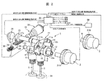
- FIG. 2 is a perspective view illustrating an external configuration of an intake-side variable valve mechanism and an exhaust-side variable valve mechanism.
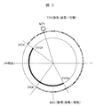
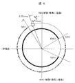
- FIG. 6 is an explanatory diagram illustrating a relationship between an opening / closing timing of an exhaust valve and an intake valve at a fourth load and an ignition timing according to the first embodiment of the present invention.
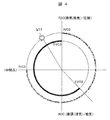
- FIG. 4 is an explanatory diagram illustrating a relationship between an opening / closing timing of an exhaust valve and an intake valve at a third load and an ignition timing according to the first embodiment of the present invention.
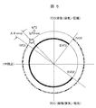
- FIG. 4 is an explanatory diagram illustrating a relationship between an opening / closing timing of an exhaust valve and an intake valve under a second load, and an ignition timing according to the first embodiment of the present invention.
- FIG. 2 is an explanatory diagram illustrating a relationship between an opening / closing timing of an exhaust valve and an intake valve at a first load and an ignition timing according to the first embodiment of the present invention.
- FIG. 4 is an explanatory diagram illustrating a relationship between lifts, opening / closing timings, and ignition timings of an exhaust valve and an intake valve from a first load to a fourth load corresponding to progress of a rotation angle according to the first embodiment of the present invention. is there.
- FIG. 1 is there.
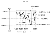
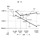
- 4 is a diagram illustrating a change in the opening / closing timing of an exhaust valve and an intake valve from a first load to a fourth load and a change in an ignition timing according to the first embodiment of the present invention.
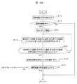
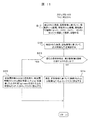
- 4 is a flowchart illustrating a first half of a control flow for executing control in the control system for an internal combustion engine according to the first embodiment of the present invention.
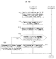
- 4 is a flowchart illustrating the latter half of the control flow for executing control in the control system for an internal combustion engine according to the first embodiment of the present invention. It is a flowchart which shows the control flow which becomes 2nd Embodiment of this invention. It is a flowchart which shows the control flow which becomes 3rd Embodiment of this invention.
- FIG. 14 is an explanatory diagram illustrating a relationship between a rotation speed of an internal combustion engine and a rotation correction cow degree according to a fifth embodiment of the present invention.
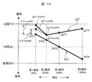
- FIG. 14 is a diagram illustrating a change in the opening / closing timing of an exhaust valve and an intake valve from a first load to a fourth load and a change in an ignition timing according to a fifth embodiment of the present invention. It is a flowchart which shows the control flow which becomes 5th Embodiment of this invention.
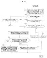
- FIG. 16 is an explanatory diagram illustrating a relationship between a seating detection signal and a knock detection signal according to a sixth embodiment of the present invention. It is a flowchart which shows the control flow which becomes 6th Embodiment of this invention.
- FIG. 17 is an explanatory diagram illustrating a change in the opening / closing timing of the exhaust valve and the intake valve from the first load to the fourth load and a change in the ignition timing according to the seventh embodiment of the present invention.
- a combustion chamber 04 is formed between a cylinder block 01 and a cylinder head 02 via a piston 03, and an ignition plug 05 is provided at a substantially central position of the cylinder head 02.
- the piston 03 is connected to a crankshaft 07 via a connecting rod 06 having one end connected to a piston pin.
- the crankshaft 07 is designed such that a normal start in cold operation and an automatic start after idling stop are performed by a starter motor 08 via a pinion gear mechanism 09.
- the crankshaft 07 is configured to detect a crank angle and a rotation speed by a crank angle sensor 010 described later.
- a knock sensor 015 for detecting occurrence of knock and a water temperature sensor 011 for detecting water temperature in the water jacket are attached to the cylinder block 01, and fuel is injected into the combustion chamber 04 to the cylinder head 02.
- a fuel injection valve 012 is provided.
- two intake valves 4 and two exhaust valves 5 are provided for each cylinder for opening and closing an intake port 013 and an exhaust port 014 formed inside the cylinder head 02, respectively.
- a variable valve mechanism is provided on the exhaust valve 5 side.
- An intake valve timing control mechanism (hereinafter referred to as an intake VTC mechanism) 3 is provided on the intake valve side, and an exhaust valve lift control mechanism (hereinafter referred to as an exhaust VEL mechanism) 1 is provided on the exhaust valve side.
- an exhaust side valve timing control mechanism (hereinafter referred to as an exhaust side VTC mechanism) 2.
- the control means (controller) 22 receives a sensor signal as shown in the figure and outputs a drive signal for the control element.
- a starter motor 08 shown in FIG. 1 is a general motor comprising a motor body powered by a battery, a pinion gear mechanism 09 that meshes with a ring gear fitted on the outer periphery of a flywheel and transmits power. is there. Only when the starter motor 08 is energized at the time of starting or restarting, the pinion gear of the pinion gear mechanism 09 moves forward, meshes with the ring gear of the internal combustion engine, and transmits the rotation of the starter motor 08 to a well-known ring gear to crank. Done. When the internal combustion engine is successfully started and power supply to the starter motor 08 is stopped, the pinion gear is pushed back, and the engagement with the ring gear is released.
- the present embodiment is directed to controlling the exhaust valve 5 to a predetermined opening / closing timing and controlling the intake valve 4 to a predetermined opening / closing timing, as described later.
- the crank pulley may be rotated by a belt drive using a starter in which the pinion gear and the ring gear are always meshed, a motor for a hybrid vehicle, or the like.
- variable valve mechanism controls the exhaust-side VEL mechanism 1 that controls the valve lift and the operating angle (open period) of the exhaust valve 5 of the internal combustion engine, and the opening / closing timing (valve timing) of the exhaust valve 5.
- An exhaust-side VTC mechanism 2 for controlling and an intake-side VTC mechanism 3 for controlling the opening / closing timing of the intake valve 4 are provided.
- the operation of the exhaust-side VEL mechanism 1, the exhaust-side VTC mechanism 2, and the intake-side VTC mechanism 3 is controlled by the control unit 22 in accordance with the engine operating state.
- the exhaust-side VEL mechanism 1 has the same configuration as that described in, for example, Japanese Patent Application Laid-Open No. 2003-172112 (applied to the intake valve side) previously filed by the present applicant. I want to be.
- the intake-side VTC mechanism 3 also has the same configuration as that described in, for example, Japanese Patent Application Laid-Open No. 2012-127219 filed earlier by the present applicant. For details, refer to this publication.
- the exhaust-side VTC mechanism 2 has substantially the same configuration as the intake-side VTC mechanism 3.
- the exhaust-side VEL mechanism 1 will be briefly described with reference to FIG. 2.
- a hollow drive shaft 6 rotatably supported by a bearing provided at an upper portion of a cylinder head 02 and a drive shaft 6 are fixed to the outer peripheral surface by press fitting or the like.
- the exhaust valve 5 is opened by being slidably supported on the provided rotary cam 7 and the outer peripheral surface of the drive shaft 6 and in sliding contact with the upper surface of a valve lifter 8 disposed at the upper end of the exhaust valve 5.
- a transmission that is interposed between the two swing cams 9 and between the rotation cam 7 and the swing cam 9, converts the rotational force of the rotation cam 7 into a swing motion, and transmits the swing force to the swing cam 9 as a swing power.
- the drive shaft 6 (exhaust side) is transmitted a rotational force from a crankshaft 07 via a timing sprocket 31A provided at one end by a timing chain, and the rotational direction is clockwise (arrow direction) in FIG. Is set.
- a system in which the phase between the drive shaft 6 and the timing sprocket 31A does not change may be adopted.
- the exhaust-side VTC mechanism 2 is mounted but not used, and no phase conversion is performed. Therefore, the exhaust-side VTC mechanism 2 may be omitted, and the timing sprocket 31A may be fixed.
- the rotating cam 7 on the exhaust side has a substantially ring shape, is fixed to the driving shaft 6 through a driving shaft insertion hole formed in the inner axial direction, and the axis of the cam body is the axis of the driving shaft 6. Is offset by a predetermined amount in the radial direction.
- the swing cam 9 is integrally provided at both ends of a cylindrical camshaft 10, and the camshaft 10 is rotatably supported on the drive shaft 6 via an inner peripheral surface.
- a cam surface including a base circle surface, a ramp surface, and a lift surface is formed on the lower surface, and the base circle surface, the ramp surface, and the lift surface correspond to the swing position of the swing cam 9 of each valve lifter 8. It comes into contact with a predetermined position on the upper surface.
- the transmission mechanism includes a rocker arm 11 disposed above the drive shaft 6, a link arm 12 for linking one end 11 a of the rocker arm 11 and the rotating cam 7, and another end 11 b of the rocker arm 11 and the swing cam 9. And a link rod 13 for linking.
- the rocker arm 11 has a cylindrical base at the center rotatably supported by a control cam, which will be described later, via a support hole, and one end 11 a is rotatably connected to the link arm 12 by a pin 14. The other end 11 b is rotatably connected to one end 13 a of the link rod 13 via a pin 15.
- the cam body of the rotary cam 7 is rotatably fitted in a fitting hole formed at the center position of the annular base end 12a, while a protruding end 12b protruding from the base end 12a has a pin.
- 14 is connected to the rocker arm end 11a.
- the other end of the link rod 13 is rotatably connected to a cam nose portion of the swing cam 9 via a pin 16.
- the control shaft 17 is rotatably supported by the same bearing member at a position above the drive shaft 6, and is slidably fitted in the support hole of the rocker arm 11 on the outer periphery of the control shaft 17 to swing the rocker arm 11.
- a control cam 18 serving as a fulcrum is fixed.
- the control shaft 17 is disposed in the engine front-rear direction in parallel with the drive shaft 6, and the rotation of the control shaft 17 is controlled by a drive mechanism 19.
- the control cam 18 has a cylindrical shape, and the axial center position is deviated by a predetermined amount from the axial center of the control shaft 17.
- the drive mechanism 19 includes an electric motor 20 fixed to one end of the casing, and a ball screw transmission mechanism 21 that transmits the rotational driving force of the electric motor 20 to the control shaft 17.
- the electric motor 20 is constituted by a proportional DC motor, and is driven by a control signal from a control means 22 for detecting an operating state of the engine.
- the ball screw transmission mechanism 21 includes a ball screw shaft 23 disposed substantially coaxially with a drive shaft of the electric motor 20, a ball nut that is a moving member screwed around the outer periphery of the ball screw shaft 23, and one end of the control shaft 17. It mainly includes a link arm 25 connected to the portion along the diameter direction, and a link member 26 linking the link arm 25 and the ball nut 24.
- the ball screw shaft 23 has a ball circulation groove having a predetermined width continuously formed in a spiral shape on the entire outer peripheral surface except for both end portions, and is connected to one end portion via a motor drive shaft, and is rotationally driven by the electric motor 20. It is supposed to be.
- the ball nut 24 is formed in a substantially cylindrical shape, and a guide groove for rotatably holding a plurality of balls in cooperation with a ball circulation groove is formed continuously in a spiral shape on the inner peripheral surface. , The rotational motion of the ball screw shaft 23 is converted into the linear motion of the ball nut 24, and an axial moving force is applied.
- the ball nut 24 is urged toward the electric motor 20 (minimum lift side) by the spring force of a coil spring 30 as urging means. Therefore, when the engine is stopped, the ball nut 24 moves to the minimum lift side along the axial direction of the ball screw shaft 23 by the spring force of the coil spring 30.
- the exhaust-side VTC mechanism 2 and the intake-side VTC mechanism 3 are of a so-called vane type. Since the configuration is the same as that described in Japanese Patent Application Laid-Open Publication No. H10-209, the description is omitted here.
- the "most advanced position" is the default position for the exhaust-side VTC mechanism 2 and the intake-side VTC mechanism 3.
- the default position is a position that is mechanically stable when not operating, that is, when no hydraulic pressure is applied.
- the lift, the operating angle, and the opening / closing timing of the exhaust valve 5 are controlled in accordance with the operations of the exhaust-side VEL mechanism 1 and the exhaust-side VTC mechanism 2.
- the opening and closing timing of the intake valve 4 is controlled in accordance with the operation of the intake-side VTC mechanism 3, but the lift and operating angle of the intake valve 4 do not change.
- the lift / operating angle of the intake valve is set to be substantially the same as the lift / operating angle by the exhaust-side VEL mechanism 1 in the second load region shown in FIG.
- control means 22 is incorporated inside the control unit (ECU), and detects a detection signal from the crank angle sensor 010 for detecting the crank angle, a detection signal from the accelerator opening sensor, and a detection signal from the vehicle speed sensor.
- the current engine operating state and the vehicle operating state are detected from the detection signal from the gear position sensor, the detection signal from the brake depression sensor, the detection signal from the water temperature sensor 011, the detection signal from the knock sensor 015, and the like.
- a detection signal from a drive shaft angle sensor 28 that detects the rotation angle of the drive shaft 6 and a detection signal from a potentiometer 29 that detects the rotation position of the control shaft 17 are input to determine the relative position of the drive shaft 6 with respect to the crank angle. The rotation angle, the valve lift of the exhaust valve 5 and the operating angle are detected.
- the control means 22 includes a microcomputer as a main component.
- the microcomputer includes an arithmetic unit that executes arithmetic processing according to a control program, and a ROM area unit that stores a control program, constants used for the arithmetic operation, and the like. And a RAM area as a work area for temporarily storing data required during the execution of the program. Further, there is provided an I / OLSI or the like that captures sensor signals and supplies drive signals to drive actuators such as the exhaust-side VEL mechanism 1, the exhaust-side VTC mechanism 2, and the intake-side VTC mechanism 3.
- the microcomputer performs various arithmetic processes related to control executed by the exhaust-side VEL mechanism 1, the exhaust-side VTC mechanism 2, the intake-side VTC mechanism 3, and the like according to a control program.
- the processing executed by the calculation is regarded as a function.
- the microcomputer is provided with an ignition timing control function for controlling the ignition timing of the ignition plug 05, a fuel injection control function for controlling the injection amount and the injection timing of the fuel injection valve 012, and the like.
- control means 22 is configured in one of at least two forms described below.
- variable valve mechanism control means for controlling the exhaust-side VEL mechanism 1, the exhaust-side VTC mechanism 2, and the intake-side VTC mechanism 3, and an ignition timing control means for controlling the ignition timing of the spark plug (fuel injection control means).
- ignition timing control means for controlling the ignition timing of the spark plug (fuel injection control means).
- variable valve mechanism control means and the ignition timing control means are connected via a communication line, and respective control information is transmitted and received by communication, and a control flow described later is executed.
- variable valve mechanism control means for controlling the exhaust side VEL mechanism 1, the exhaust side VTC mechanism 2, and the intake side VTC mechanism 3, and an ignition timing control means (fuel injection control means) for controlling the ignition timing of the spark plug.
- ignition timing control means fuel injection control means
- the ignition timing control will be briefly described.
- a basic ignition timing determined by the rotational speed and the load is obtained, and various correction ignition timings are added or subtracted from the basic ignition timing to obtain a final ignition timing.
- a corrected ignition timing such as water temperature correction, acceleration correction, deceleration correction, and knock feedback correction is used.
- the load table stores advance correction side ignition timing that advances as the load decreases, and from this table, the correction ignition timing corresponding to the load is stored. Is read and added to the basic ignition timing to calculate the final ignition timing.
- the corrected ignition timing in the load table may be reflected in the basic ignition timing map in which the basic ignition timing is stored.
- the following Atkinson cycle is executed by using the exhaust VEL mechanism 1, the exhaust VTC mechanism 2, and the intake-side VTC mechanism 3 that perform such operations in combination.
- FIG. 3 shows the opening / closing timing and ignition timing of the intake / exhaust valve of the fourth load (full load) with a load factor of 100%
- FIG. 4 shows the intake / exhaust of the third load (medium load) with a load factor of 50%
- FIG. 5 shows the opening / closing timing and ignition timing of the intake / exhaust valve of the second load (low load) having a load factor of 20%
- FIG. 6 shows the opening / closing timing and ignition timing of the valve at a load factor of 0%. It shows the opening / closing timing and ignition timing of the intake / exhaust valve for one load (idle, light load).
- FIG. 7 shows the valve lifts and open states of the exhaust valve 5 and the intake valve 4 and the ignition timing corresponding to the advance of the rotation angle at the load described above.
- FIG. 8 shows the first to fourth loads. Up to the change in the opening and closing timing of the exhaust valve and the intake valve, and the change in the ignition timing.
- the point (TDC) includes exhaust (intake) top dead center (TDC) and compression top dead center (TDC).
- TDC top dead center
- BDC compression top dead center
- BDC bottom dead center
- BDC intake bottom
- IVO hereinafter referred to as an intake opening timing
- IVO4 intake opening timing
- TDC intake top dead center
- IVC intake closing timing
- BDC intake bottom dead center
- IVC4 intake closing timing
- the valve opening timing of the exhaust valve 5 (EVO: hereinafter referred to as the exhaust opening timing) is set to the exhaust opening timing (EVO4) slightly advanced from the exhaust (expansion) bottom dead center (BDC).
- the valve closing timing (EVC: hereinafter referred to as exhaust closing timing) of the valve 5 is set to the exhaust closing timing (EVC4) having the same angle as the intake opening timing (IVO4) of the intake valve 4.
- the opening timing (IVO4) of the intake valve 4 and the closing timing (EVC4) of the exhaust valve 5 have the same angle, and a zero overlap is formed. As a result, a reduction in combustion speed due to internal EGR can be suppressed, and thermal efficiency can be improved.
- the ignition timing (IgT) of the fourth load is set to the ignition timing (IgT4) on the advance side from the compression top dead center (TDC).
- the ignition timing (IgT4) is the most retarded side and close to the compression top dead center (TDC) and slightly advanced from the compression top dead center (TDC) among the first to third loads described later. Is set.
- the intake closing timing (IVC4) of the intake valve is set at a position close to the intake bottom dead center (BDC), so that the charging efficiency can be increased, and sufficient engine torque can be obtained. Can be obtained.
- Third Load (Medium Load) >> In FIGS. 4 and 7, the third load (medium load: a load factor of 50%), and in FIG. 8, the third load, which is a middle load, has a larger intake air than the fourth load.
- the intake timing (IVO3) of the valve 4 is shifted to the retard side to be set to the intake opening timing (IVO3) which coincides with the intake (exhaust) top dead center (TDC).
- IVC) is also shifted to the retard side, and is set to the intake closing timing (IVC3) which is an intermediate point between the intake bottom dead center (BDC) and the compression top dead center (TDC).
- the exhaust valve opening timing (EVO) of the exhaust valve 5 is shifted to the advanced side as compared with the fourth load, and the exhaust valve is opened.
- the timing (EVO3) is set, and conversely, the closing timing (EVC) of the exhaust valve 5 is shifted to the retard side as compared with the fourth load, and is set as the exhaust closing timing (EVC3).
- the ignition timing (IgT) of the third load is set to an ignition timing (IgT3) on the advance side as compared with the ignition timing of the fourth load (IgT4).
- the intake closing timing (IVC3) is retarded compared to the intake closing timing (IVC4) of the intake valve 4 of the fourth load, so that pump loss can be suppressed.
- the exhaust opening timing (EVO3) of the exhaust valve 5 is advanced, the timing at which the in-cylinder pressure decreases to the atmospheric pressure in the expansion stroke is advanced with the decrease in load compared to the fourth load. Is opened at the exhaust opening timing (EVO3), so that the pump loss in the so-called expansion stroke can be suppressed, and the fuel efficiency under a medium load can be reduced.
- the exhaust valve closing timing (EVC3) of the exhaust valve 5 is also retarded by the same angle in accordance with the retard of the intake opening timing (IVO3) of the intake valve 4, so that the zero valve overlap can be maintained. .
- EVC3 exhaust valve closing timing
- IVO3 intake opening timing
- the ignition timing (IgT3) is set on the advance side as compared with the fourth load.
- the intake closing timing (IVC3) is greatly separated from the intake bottom dead center (BDC).
- the effective compression ratio is reduced, and the mixed gas is reduced to decrease the combustion speed. Therefore, the ignition timing (IgT3) is advanced from the ignition timing (IgT4) of the fourth load, so that the peak combustion pressure is reduced. This is because the time of occurrence is adjusted to the time when high thermal efficiency is obtained.
- the intake closing timing (IVC) shifts in a direction of retarding.
- the intake closing timing (IVC) is controlled to the retard side, the pump loss can be suppressed, so that the fuel consumption can be reduced.
- Second Load (Low Load) In the second load (low load: load factor 20%) shown in FIGS. 5 and 7, and in FIG. 8, the low load second load is larger than the third load.
- the intake opening timing (IVO2) of the valve 4 is shifted to the retard side from the intake (exhaust) top dead center (TDC) and is set to the intake opening timing (IVO2), and the intake closing timing (IVC2) of the intake valve 4 is set.
- the exhaust opening timing (EVO) of the exhaust valve 5 is shifted to the advanced side as compared with the third load, and the exhaust opening timing is increased. (EVO3), and conversely, the closing timing (EVC) of the exhaust valve 5 is shifted to the retard side exceeding the exhaust top dead center (TDC) compared to the third load, and the exhaust closing timing (EVC3) Is set to
- the ignition timing (IgT) of the second load is set to (IgT2) at the ignition timing on the more advanced side as compared with the ignition timing of the third load (IgT3).
- the intake closing timing (IVC2) is retarded compared to the intake closing timing (IVC3) of the intake valve 4 of the third load, pump loss can be further suppressed.
- the exhaust opening timing (EVO2) of the exhaust valve 5 is advanced, the timing at which the in-cylinder pressure decreases to the atmospheric pressure in the expansion stroke with the decrease in the load is advanced as compared with the third load. By opening at the exhaust opening timing (EVO2), it is possible to suppress a pump loss in a so-called expansion stroke, and to reduce fuel consumption at a low load.
- the ignition timing (IgT2) is set on the advance side as compared with the third load.
- the intake closing timing (IVC2) is greatly separated from the intake bottom dead center (BDC). Since the effective compression ratio is reduced and the mixed gas is reduced to lower the combustion speed, a peak combustion pressure is generated by advancing the ignition timing (IgT2) from the ignition timing (IgT3) of the third load. This is because the time is adjusted to the time when high thermal efficiency is obtained.
- the ignition timing (IgT) is controlled so that the ignition is always performed on the retard side with respect to the intake closing timing (IVC).
- the ignition timing (IgT2) is greatly advanced, and the ignition timing (IgT2) is set to the angle difference threshold ( ⁇ sld) to the intake closing timing (IVC2). If it is assumed that the ignition timing (IgT2) has advanced beyond the intake closing timing (IVC2), the ignition timing (IgT2) becomes as shown in the second load of FIG. 5 and FIG. Starting from the intake valve closing timing (IVC2) of the intake valve, a new ignition timing (IgT2new) having a predetermined correction angle ( ⁇ cmp) on the retard side is set.
- the correction angle ( ⁇ cmp) is set to the same value as the angle difference threshold value ( ⁇ sld), but is not limited thereto, and the correction angle ( ⁇ cmp) may be set to a value larger than the angle difference threshold value ( ⁇ sld). Is also possible.
- the currently calculated ignition timing (IgT2) is advanced beyond the intake closing timing (IVC2)
- the currently calculated intake closing timing (IVC2) of the intake valve 4 is calculated.
- a value obtained by retarding only the predetermined correction angle ( ⁇ cmp) as the starting point may be reset as a new ignition timing (IgT2new).
- the mixed gas can be ignited without the ignition timing (IgT) always exceeding the intake closing timing (IVC).
- First load (idle / light load)) >> In the first load (idle / light load: 0% load factor) shown in FIGS. 6 and 7, and in FIG.
- the intake timing (IVO1) of the intake valve 4 is shifted to the retard side, and further shifted to the retard side from the intake top dead center (TDC).
- the intake opening timing (IVO1) approaching the middle point of the intake bottom dead center (BDC) is set, and the intake closing timing (IVC) of the intake valve 4 is also shifted to the retard side, so that the intake bottom dead center (BDC) And is retarded from the middle point between the compression top dead center (TDC) and the intake closing timing (IVC1).
- the exhaust opening timing (EVO) of the exhaust valve 5 is shifted to the advanced side as compared with the second load, and the exhaust valve is opened.
- the timing (EVO1) is set, and conversely, the closing timing (EVC) of the exhaust valve 5 is shifted to the retard side as compared with the second load, and is set as the exhaust closing timing (EVC1).
- the ignition timing of the first load (IgT) is set to the same ignition timing as the ignition timing of the second load (IgT2).
- the intake closing timing (IVC1) is retarded compared to the intake closing timing (IVC2) of the intake valve of the second load, pump loss can be further suppressed.
- the exhaust valve opening timing (EVO1) of the exhaust valve is advanced, the timing at which the in-cylinder pressure decreases to the atmospheric pressure in the expansion stroke is earlier than the second load as the load decreases. By opening at the timing (EVO1), it is possible to suppress the pump loss in the so-called expansion stroke and to reduce the fuel consumption at a partial load.
- the exhaust valve closing timing (EVC1) of the exhaust valve 5 is also retarded by the same angle in accordance with the retardation of the intake opening timing (IVO1) of the intake valve 4, so that the zero valve overlap can be maintained. .
- EVC1 exhaust valve closing timing
- IVO1 intake opening timing
- the ignition timing (IgT1) is such that, at the first load, the intake closing timing (IVC1) is greatly separated from the intake bottom dead center (BDC), and the effective compression ratio is lowered. Since the ignition timing (IgT1) is advanced in the same manner as the ignition timing (IgT2) of the second load, the timing at which the peak combustion pressure occurs is matched with the timing at which high thermal efficiency is obtained.
- the intake closing timing (IVC1) is largely shifted to the retard side, and the ignition timing (IgT1) is advanced greatly.
- the ignition timing (IgT) is controlled so as not to be smaller than a predetermined angle difference threshold value ( ⁇ sld).
- the ignition timing (IgT1) approaches the intake closing timing (IVC1) beyond the angle difference threshold value ( ⁇ sld), or when the ignition timing (IgT1) is advanced beyond the intake closing timing (IVC1), As shown in the first load of FIGS. 6 and 7, the ignition timing (IgT1) is the ignition timing (IgT1new) delayed from the intake valve closing timing (IVC1) of the intake valve by a predetermined correction angle ( ⁇ cmp). ) Is set.
- the intake valve calculated at the present time is advanced.
- a value delayed from the intake closing timing (IVC1) by a predetermined correction angle ( ⁇ cmp) may be reset as a new ignition timing (IgT1new).
- the retardation of the ignition timing (IgT1) also retards the peak combustion pressure generation timing and lowers the thermal efficiency by that amount, but the retard amount (correction angle ⁇ cmp) prevents the occurrence of backfire. Is suppressed to only a small amount, so that the reduction in the effect of reducing the fuel consumption at the first load can be reduced as much as possible.
- the retardation of the ignition timing (IgT1), the temperature of the exhaust gas rises, and it is possible to suppress an increase in harmful exhaust components due to a decrease in the temperature of the exhaust gas purifying catalyst, which is a problem during idling or light load.
- the correction angle ( ⁇ cmp) is set to 4 to 8 in terms of crank angle. According to this, even if the intake closing timing (IVC) fluctuates due to the intake-side VTC mechanism 3, the backfire is reliably prevented, and the excessive retardation of the ignition timing (IgT) is suppressed to suppress the fuel. An increase in consumption can be suppressed.
- the fluctuation of the intake closing timing (IVC) due to the rotation fluctuation or the like is about 2 to 4 in crank angle. Therefore, it is desirable that the correction angle ( ⁇ cmp) be 4 or more.
- the correction angle ( ⁇ cmp) is increased unnecessarily, the ignition timing (IgT) is retarded by that amount, which causes an increase in fuel consumption.
- the crank angle is suppressed to a range of 8 ° in consideration of a safety factor.
- the correction angle ( ⁇ cmp) is set to 4 to 8 in terms of the crank angle
- the fluctuation of the intake closing timing (IVC) due to the rotation fluctuation and the like, and the fuel consumption due to the retardation of the ignition timing (IgT) are taken into consideration.
- An increase in the amount can be suppressed as much as possible.
- This control flow is executed by the control means 22 every time a predetermined time elapses.
- a control flow when starting the operation of the internal combustion engine will be described based on FIGS. 9A and 9B.
- the ignition timing (IgT) approaches the intake closing timing (IVC) or the ignition timing (IgT) changes the intake closing timing (IVC) over all the operating load states. It is to judge whether it has exceeded.
- step S10 engine start information for starting the internal combustion engine and operating state information of the internal combustion engine are read.
- the engine start information for starting the internal combustion engine typically includes a key-on signal or a starter start signal, and there are many signals indicating operation state information of the internal combustion engine.
- the information includes rotational speed information, intake air amount information, water temperature information, required load information (accelerator opening), and the like, and further includes actual position information of the exhaust-side VTC mechanism 1B and the intake-side VTC mechanism 1A.
- step S11 it is determined whether an engine start condition is satisfied. This determination can be made, for example, by monitoring the starter start signal. If the starter start signal is not input, the process returns to the start and waits for the next start timing. On the other hand, when the starter start signal is input, it is determined that an engine start condition is satisfied, and the process proceeds to step S12.
- step S12 the cranking of the internal combustion engine by the starter motor is started in response to the starter start signal. Then, as soon as the cranking is started, the process proceeds to step S13.
- step S13 at least the exhaust opening / closing timing (EVO) of the exhaust valve 5 is set so that the exhaust-side VEL mechanism 1, the exhaust-side VTC mechanism 2, and the intake-side VTC mechanism 3 shift to the default positions.
- EVC) and the conversion control signals of the intake opening / closing timing (IVO) of the intake valve 4 and (IVC) are output to the exhaust-side VEL mechanism 1, the exhaust-side VTC mechanism 2, and the intake-side VTC mechanism 3.
- the conversion control signal is output to the exhaust side VEL mechanism 1, the exhaust side VTC mechanism 2, and the intake side VTC mechanism 3, the process proceeds to step S14.
- Step 14 From the actual position information of the exhaust side VEL mechanism 1, the exhaust side VTC mechanism 2, and the intake side VTC mechanism 3, the exhaust side VEL mechanism 1, the exhaust side VTC mechanism 2, and the intake side VTC mechanism are used. It is determined whether 3 has moved to the default position.
- step S15 When it is determined that the exhaust-side VEL mechanism 1, the exhaust-side VTC mechanism 2, and the intake-side VTC mechanism 3 have not shifted to the default positions, the process returns to step S13, and the exhaust-side VEL mechanism 1, the exhaust-side VTC mechanism, and so on. If it is determined that the VTC mechanism 2 and the intake-side VTC mechanism 3 are set to the default position, the process proceeds to step S15.
- step S15 an output control signal is supplied to the fuel injection valve and the ignition device to start the internal combustion engine in accordance with the rotation of the starter motor.
- the rotation speed of the internal combustion engine increases, and accordingly, the hydraulic pressure of the hydraulic oil of the hydraulic pump increases.
- the intake-side VTC mechanism 3 is at the “most advanced position” that is the default position, specifically, the intake closing timing (IVC4) close to the bottom dead center shown in FIG. 4 (high load). ), It is possible to increase the intake air charging efficiency, increase the combustion torque during a cold period in which the engine friction is large, and obtain good starting combustion that overcomes the engine friction.
- the exhaust side VEL mechanism 1 moves to the default position of “minimum lift / minimum operating angle position”.
- the exhaust-side VTC mechanism 2 is at a default position, ie, the “most advanced position”. Specifically, as shown in FIG. 4 (high load), the exhaust opening timing (EVO4) near the bottom dead center is reached. Therefore, by delaying the opening of the exhaust valve and sufficiently warming the engine body with the combustion gas, the warm-up property of the engine body at the time of cold is improved.
- variable valve mechanisms 1 to 3 are originally located near the default position, which is a mechanically stable position, so that the above-described cold-time effect can be obtained without delay from the initial stage of the start.
- step S16 the engine temperature (cooling water temperature) of the internal combustion engine is detected to determine whether or not the temperature has exceeded a predetermined temperature. If the temperature does not exceed the predetermined temperature, it is determined that the engine is in the cold state, and the process returns to wait for the next start timing or executes another control flow. On the other hand, if the temperature exceeds the predetermined temperature, it is determined that the warm-up from the cold state has been completed, and the process proceeds to step S17. It should be noted that FIG. 9B shows the steps after step S17.
- step S17 the opening / closing timing (EVO) and (EVC) of the exhaust valve 5 and the opening / closing timing (IVO) and (IVC) of the intake valve 4 are determined based on the operating state information detected in step S10. Calculate. This calculation is basically obtained from an opening / closing timing map of the exhaust valve 5 and an opening / closing timing map of the intake valve 4 mapped by the rotation speed and the load.
- the opening / closing timings (EVO) and (EVC) of the exhaust valve 5 and the opening / closing timings (IVO) and (IVC) of the intake valve 4 calculated from the map correspond to the corresponding exhaust-side VEL mechanism 1 and exhaust-side VTC mechanism 2. , And is sent to the intake side VTC mechanism 3 to drive and control the exhaust valve 5 and the intake valve 4. Upon completion of the process in the step S17, the process shifts to a step S18.
- step S18 an ignition timing (IgT) is calculated based on the operating state information detected in step S10.
- This ignition timing (IgT) is first obtained from a basic ignition timing map mapped by the rotation speed and the load.
- the final ignition timing (IgT) is obtained by adding and subtracting various corrected ignition timings to and from the basic ignition timing retrieved from the map.
- the ignition timing (IgT) needs to be advanced, so that the corrected ignition timing is read from the correction table which is corrected to the advanced side in accordance with the decrease in the load. Is reflected in the basic ignition timing.
- the ignition timing (IgT) is determined, the process proceeds to step S19.
- step S20 first, it is determined whether or not the actual angle difference ( ⁇ act) obtained in step 19 is smaller than a predetermined angle difference threshold value ( ⁇ sld). If the actual angle difference ( ⁇ act) has a plus (+) sign, it can be determined that the intake closing timing (IVC) is set to be more advanced than the ignition timing (IgT). In this case, if the actual angle difference ( ⁇ act) is larger than the angle difference threshold value ( ⁇ sld), it is determined that there is no risk of backfire. However, if the actual angle difference ( ⁇ act) is smaller than the angle difference threshold value ( ⁇ sld), it is determined that the ignition timing (IgT) approaches the intake closing timing (IVC) and the risk of backfire is high.
- ⁇ sld a predetermined angle difference threshold value
- step S20 in addition to the above-described determination operation, it is also determined whether or not the calculation result for obtaining the actual angle difference ( ⁇ act) has a minus ( ⁇ ) sign. Therefore, if the actual angle difference ( ⁇ act) has a minus ( ⁇ ) sign, the ignition timing (IgT) is set to be more advanced than the intake air ratio timing (IVC), which may cause a backfire. Is determined to be quite high.
- step S21 if the actual angle difference ( ⁇ act) has a plus (+) sign and the actual angle difference ( ⁇ act) is larger than the angle difference threshold value ( ⁇ sld), the process proceeds to step S21.
- the actual angle difference ( ⁇ act) has a plus (+) sign
- the actual angle difference ( ⁇ act) is smaller than the angle difference threshold ( ⁇ sld)
- the actual angle difference ( ⁇ act) has a minus ( ⁇ ) sign. If it is, the process moves to step S22.
- step S20 the actual angle difference ( ⁇ act) has a plus (+) sign, and it is determined that the actual angle difference ( ⁇ act) is larger than the angle difference threshold value ( ⁇ sld), and there is no possibility of backfire. Is considered to be.
- step S21 the ignition timing (IgT) calculated in step S18 is used as it is.
- the ignition timing (IgT) is set in an ignition register of the I / OLSI of the microcomputer, and the ignition operation is performed at a predetermined timing.
- step S20 the actual angle difference ( ⁇ act) has a plus (+) sign, and it is determined that the actual angle difference ( ⁇ act) is smaller than the angle difference threshold value ( ⁇ sld), or Since ⁇ act) has a minus ( ⁇ ) sign, it is considered that there is a risk of backfire.
- step S22 the ignition timing (IgT) calculated in step S18 is not used as it is, and the ignition timing (IgT) is retarded from the intake closing timing (IVC) and the intake closing timing (IVC).
- An ignition timing (IgTnew) delayed by a predetermined correction angle ( ⁇ cmp) is newly set.
- the new ignition timing (IgTnew) is always set to the retard side from the intake closing timing (IVC), so that the possibility of occurrence of backfire can be suppressed.
- This new ignition timing (IgTnew) is set in an ignition register of the I / OLSI of the microcomputer, and the ignition operation is executed at a predetermined timing.
- the intake closing timing (IVC) of the intake valve is controlled to the retard side by the intake-side variable valve mechanism.
- the ignition timing (IgT) is controlled to an advanced side by the ignition timing, and the ignition timing (IgT) is retarded from the intake closing timing (IVC), and the angle between the intake closing timing (IVC) and the ignition timing (IgT). The difference is always maintained at or above a predetermined correction angle ( ⁇ cmp).
- the intake closing timing (IVC) of the intake valve is greatly retarded by the intake side variable valve mechanism to increase the effect of reducing the fuel consumption by the Atkinson cycle, and the ignition timing (IgT) is advanced.
- the ignition timing (IgT) is not advanced beyond the intake closing timing (IVC), so that backfire can be suppressed.
- the load at which the ignition timing (IgT) approaches the intake closing timing (IVC) is known to be a load smaller than the predetermined load, so that the load is limited to the predetermined load or less. Steps 19 to S22 are executed.
- steps S26 and S27 show the response at the time of failure, which will be described later.
- Step S23 In FIG. 10, a step S23 is newly provided between steps S18 and S19.
- the current load is determined based on the operating state information detected in step S10. If it is determined that the load is larger than the second load, the process proceeds to step S24, where the load is changed from the second load. If it is determined that it is smaller, the process moves to step S19.
- step S19 to step S22 is the same as the processing shown in FIG. 9B, and a description thereof will not be repeated.
- Step S24 the ignition timing (IgT) does not become close to the intake closing timing (IVC) at the fourth load and the third load where the load is larger than the second load.
- the set ignition timing (IgT) is used as it is.
- the ignition timing (IgT) is set in an ignition register of the I / OLSI of the microcomputer, and the ignition operation is performed at a predetermined timing.
- the ignition timing (IgT) approaches the intake closing timing (IVC) or the ignition timing (IgT) changes to the intake closing timing only for a load smaller than the predetermined load, for example, the second load. Since it is determined whether or not the time (IVC) has been exceeded, the calculation load on the microcomputer can be reduced.
- step S23 the current load is determined based on the operating state information detected in step S10. If it is determined that the load is larger than the second load, the process proceeds to step S24. If it is determined that the load is smaller than the second load, the process proceeds to step S25.
- step S25 when the load is smaller than the second load, the ignition timing (IgT) approaches the intake closing timing (IVC), or the ignition timing (IgT) may exceed the intake closing timing (IVC). Considering this, a predetermined correction angle ( ⁇ cmp) is uniformly subtracted from the intake closing timing (IVC) obtained in step S17 to obtain a new ignition timing (IgTnew).
- the ignition timing (IgT) calculated in step S18 is not used, and the ignition timing (IgT) is corrected to the retard side at the correction angle ( ⁇ cmp) based on the intake closing timing (IVC).
- a new ignition timing (IgTnew) is used. This new ignition timing (IgTnew) is set in an ignition register of the I / OLSI of the microcomputer, and the ignition operation is executed at a predetermined timing.
- only the predetermined correction angle ( ⁇ cmp) is subtracted uniformly from the intake closing timing (IVC) for a predetermined load, for example, only the first load and the second load.
- the calculation load can be further reduced.
- This embodiment shows a method for dealing with a case where an abnormality occurs in the intake-side VTC mechanism 3 so that a normal ignition timing (IgT) cannot be obtained.
- IgT normal ignition timing
- the intake side VTC mechanism 3 is driven in an uncontrolled state between the most retarded stopper position and the most advanced stopper position of the intake closing timing (IVC). Is done. Therefore, the ignition timing (IgT) may not be accurate. In some cases, the ignition timing (IgT) may be advanced from the intake closing timing (IVC) in the uncontrolled state. Therefore, steps S26 and S27 indicated by broken lines in FIG. 10 are executed.
- step S26 indicated by a broken line in FIG. 10, an abnormal state of the intake-side VTC mechanism 3 is determined. If it is determined that no abnormality has occurred, the process proceeds to step S18, and if it is determined that an abnormality has occurred in the intake-side VTC mechanism 3, the process proceeds to step S27.
- step S27 since the intake-side VTC mechanism 3 is in an abnormal state, the fixed ignition timing (IgTm) on the retard side from the most retarded stopper position of the intake-side VTC mechanism 3 is set. In this case, the fixed ignition timing (IgTm) is set on the retard side from the compression top dead center (TDC). Therefore, due to the abnormality of the intake side VTC mechanism 3, even if the fixed ignition timing (IgTm) is not controlled between the most retarded stopper position and the most advanced stopper position of the intake closing timing (IVC), the fixed ignition timing (IgTm) is minimized. Since the advance is not made beyond the intake closing timing (IVC) at the retard stopper position, backfire can be suppressed.
- TDC compression top dead center
- steps S26 and S27 have been described in the second embodiment shown in FIG. 10, but what can be executed after step S17 shown in FIG. 9B of the first embodiment and FIG. 11 of the third embodiment will be described. Of course.
- This embodiment shows a method for coping with a case where the actual intake closing timing (IVC) of the intake valve 4 fluctuates in the high rotation range and the ignition timing (IgT) exceeds the intake closing timing (IVC). ing.
- the present embodiment is characterized in that the correction angle ( ⁇ cmp) is set to be large in response to an increase in the number of rotations.
- FIG. 13 shows values of a correction angle table in which the horizontal axis sets the rotation speed (N) and the vertical axis sets the rotation correction angle ( ⁇ cmpN).
- a rotation correction angle ( ⁇ cmpNL) of a constant value indicated by a broken line is set on the low rotation side and a gradually increasing rotation correction angle ( ⁇ cmpNH) indicated by a solid line is set on the high rotation side, for example, at 3000 rpm. is there.
- FIG. 15 shows a control flow for realizing the characteristics shown in FIG. This control flow is executed after the "YES” determination in step S20 shown in FIGS. 9B and 10, and is executed after the "YES” determination in step S23 shown in FIG.
- step S28 a rotation correction angle ( ⁇ cmpN) is read from a correction angle table in which the characteristics shown in FIG. 13 are stored, based on the rotation speed (N) detected in step S10.
- the read rotation correction angle ( ⁇ cmpN) is used for calculation in the next step S29.
- step S29 the ignition timing (IgT) calculated in step S18 is not used as it is, and the ignition timing (IgT) is retarded from the intake closing timing (IVC) and the intake closing timing (IVC). ) Is newly set to the ignition timing (IgTnewN) retarded by the rotation correction angle ( ⁇ cmpN).
- the new ignition timing (IgTnewN) is always set to a retard side from the intake closing timing (IVC), so that the possibility of occurrence of backfire can be suppressed.
- the rotation correction angle ( ⁇ cmpN) is set to be larger as the rotation speed (N) becomes higher, the ignition is not performed even when the intake valve 4 is opened due to the bounce phenomenon. The possibility of occurrence can be further suppressed.
- the valve train resiliently deforms to cause a valve jump or valve bounce (bounce), and the actual intake closing timing (IVC) of the intake valve 4 is changed based on the control of the intake side VTC mechanism 3. There is a case where it is later than the closing time (IVC).
- the ignition timing (IgT) is corrected to be further delayed, so that the ignition timing (IgT) is always on the retard side from the intake closing timing (IVC). Can be prevented.
- the intake closing timing (IVC) of the intake valve 4 is obtained from the intake closing timing (IVC) based on the opening / closing timing map of the intake valve 4 or the actual intake closing timing (IVC) using the angle sensor.
- the intake closing timing (IVC) is obtained by the knock sensor.
- a seating determination window for the intake valve 4 is set, and an actual closing signal (vibration signal) of the intake valve 4 detected in the seating determination window is used to determine the intake closing timing of the intake valve 4.
- (IVC) can be detected. That is, as shown in FIG. 16, when it is determined that the vibration signal of the knock sensor is higher than the seating determination level in the seating determination window, the intake valve 4 is seated on the valve seat and the intake closing timing of the intake valve 4 is determined. It can be determined that (IVC) has occurred.
- the intake closing timing (IVC) of the intake valve 4 can be detected with high accuracy even if a bounce phenomenon occurs in a high rotation range, so that the ignition timing (IgT) can be reliably determined. Can be set on the retard side from the intake closing timing (IVC). For this reason, the backfire can be prevented and the ignition timing (IgT) can be made as close to the advance side as possible toward the intake closing timing (IVC), so that the fuel consumption can be further reduced.
- a knock sensor that has been conventionally used can be used as the knock sensor. As shown in FIG. 16, since a section in which knock vibration occurs (corresponding to a knock determination window) and a section in which seat vibration of the intake valve occurs (corresponding to a seat determination window) are temporally shifted, knocking occurs. Both the occurrence determination and the intake closing timing (IVC) determination are possible.
- the knock determination window exceeds the knock determination level, it can be determined that knock has occurred, and if the seat determination window is exceeded, it can be determined that the intake closing timing (IVC) has occurred. It is advantageous to mount the knock sensor on the side of the cylinder block on the intake valve side of the cylinder block, because it is difficult to detect the seated vibration of the exhaust valve.
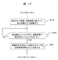
- FIG. 17 shows a control flow of a method for detecting the intake closing timing (IVC) by the knock sensor. This control flow is executed after step S18 shown in FIGS. 9B, 10, and 11.
- step S30 it is determined whether or not the vibration signal detected by the knock sensor has exceeded the seating determination level in the seating detection window. Then, when it is determined that the vibration signal of the knock sensor does not exceed the seating determination level, the process returns to step S30 again to execute the same determination operation. On the other hand, when it is determined that the vibration signal of the knock sensor has exceeded the sitting determination level, the process proceeds to step S31.
- Step S31 the crank angle corresponding to the time of occurrence of the vibration signal determined in step S30 is set as the intake closing timing (IVC) of the intake valve 4. Thereafter, it is used for the calculations in steps S19 and S20 in FIGS. 9B and 10 and in step S25 in FIG.
- IVC intake closing timing
- the intake closing timing (IVC) of the intake valve 4 can be detected with high accuracy even if a bounce phenomenon occurs in a high rotation range, so that the ignition timing (IgT) can be reliably determined.
- the knock sensor is used to detect the actual intake closing timing (IVC) of the intake valve 4.
- an actual intake closing timing (IVC) sensor may be provided separately from the knock sensor. Absent. Then, the frequency of detecting the vibration level can be suppressed, and the load on the sensor can be reduced.
- the correction angle ( ⁇ cmp) has a constant value from the second load to the first load, but in this embodiment, the correction angle ( ⁇ cmp) is set to be larger as the load becomes smaller. Things.
- the correction angle ( ⁇ cmp) is set to the correction angle ( ⁇ cmp2).
- This correction angle ( ⁇ cmp2) is set to the same value as the correction angle ( ⁇ cmp) in the first embodiment.
- the correction angle ( ⁇ cmp) is set to be large and set to the correction angle ( ⁇ cmp1). Then, there is a relationship of ( ⁇ cmp1)> ( ⁇ cmp2). As the load decreases, the correction angle ( ⁇ cmp) is set to a value that gradually increases from the correction angle ( ⁇ cmp2) to the correction angle ( ⁇ cmp1).
- the ignition timing (IgT1) at the first load is greatly retarded, the temperature of the exhaust gas rises.
- the exhaust gas purifying catalyst can be warmed up at an extremely low load where the exhaust gas purifying catalyst is unlikely to warm, and the generation of exhaust gas harmful components can be suppressed.
- the exhaust gas temperature is likely to decrease.
- the exhaust-side VTC mechanism 2 and the intake-side VTC mechanism 3 are of a hydraulic drive type.
- the present invention is not limited to the hydraulic pressure, and may be an electrically driven VTC mechanism.
- the specific form and configuration of the variable valve mechanism are not limited as long as they satisfy the gist of the present invention.
- the form of the applied internal combustion engine is not limited.
- the present invention may be applied to an internal combustion engine having a supercharger such as a turbocharger.
- the intake closing timing (IVC) at the same load as that of the naturally aspirated internal combustion engine is further retarded, so that the thermal efficiency is increased as compared with the naturally aspirated internal combustion engine. Will be able to
- the ignition timing (IgT) and the intake closing timing (IVC) approach each other due to the further retardation of the intake closing timing (IVC), so that backfire is likely to occur. Can be effectively suppressed.
- the present invention can be applied to a lean burn type internal combustion engine and an internal combustion engine which performs a large amount of EGR. It is possible to reduce the fuel consumption by lowering the combustion temperature and reducing the cooling loss by lean-burn combustion or low-temperature combustion by a large amount of EGR.
- the ignition timing (IgT) since the combustion speed is reduced by the low-temperature combustion, it is necessary to advance the ignition timing (IgT). Due to the advance of the ignition timing (IgT), the ignition timing (IgT) and the intake closing timing (IVC) are close to each other, so that a backfire is easily generated. However, the use of the present invention effectively suppresses the backfire. be able to.
- the intake closing timing (IVC) of the intake valve is controlled to the retard side by the intake-side variable valve mechanism.
- the ignition timing (IgT) is controlled to an advanced side by the ignition timing, and the ignition timing (IgT) is retarded from the intake closing timing (IVC), and the angle between the intake closing timing (IVC) and the ignition timing (IgT).
- the difference is maintained at a predetermined correction angle ( ⁇ cmp) or more.
- the intake closing timing (IVC) of the intake valve is greatly retarded by the intake side variable valve mechanism to increase the effect of reducing the fuel consumption by the Atkinson cycle, and the ignition timing (IgT) is advanced.
- the ignition timing (IgT) is not advanced beyond the intake closing timing (IVC), so that backfire can be suppressed.
- the present invention is not limited to the above-described embodiment, and includes various modifications.
- the above-described embodiments have been described in detail for easy understanding of the present invention, and are not necessarily limited to those having all the described configurations.
- a part of the configuration of one embodiment can be replaced with the configuration of another embodiment, and the configuration of one embodiment can be added to the configuration of another embodiment.
Landscapes
- Engineering & Computer Science (AREA)
- Chemical & Material Sciences (AREA)
- Combustion & Propulsion (AREA)
- Mechanical Engineering (AREA)
- General Engineering & Computer Science (AREA)
- Signal Processing (AREA)
- Output Control And Ontrol Of Special Type Engine (AREA)
- Electrical Control Of Air Or Fuel Supplied To Internal-Combustion Engine (AREA)
- Electrical Control Of Ignition Timing (AREA)
Abstract
Selon la présente invention, lorsque la charge d'un moteur à combustion interne chute, une séquence de fermeture d'admission (IVC) pour une soupape d'admission est commandée vers un côté de retard par un mécanisme de soupape variable côté admission, et une séquence d'allumage (IgT) est commandée vers un côté d'avance par un moyen de commande de séquence d'allumage, la séquence d'allumage (IgT) étant davantage vers le côté de retard que la séquence de fermeture d'admission (IVC), et la différence d'angle entre la séquence de fermeture d'admission (IVC) et la séquence d'allumage (IgT) étant maintenue au niveau ou au-dessus d'un angle de correction prescrit (Δθcmp). La séquence de fermeture d'admission (IVC) de la soupape d'admission est retardée de manière significative par le mécanisme de soupape variable côté admission de manière à améliorer les effets de réduction de consommation de carburant basés sur le cycle d'Atkinson, et la séquence d'allumage (IgT) est avancée de manière à supprimer la réduction d'un couple moteur, mais la séquence d'allumage (IgT) n'est pas avancée au-delà de la séquence de fermeture d'admission (IVC), ce qui permet de supprimer un retour d'allumage. La présente invention peut ainsi supprimer un retour d'allumage et obtenir une réduction de la consommation de carburant basée sur le cycle d'Atkinson.
Applications Claiming Priority (2)
| Application Number | Priority Date | Filing Date | Title |
|---|---|---|---|
| JP2018129247A JP2020007959A (ja) | 2018-07-06 | 2018-07-06 | 内燃機関の制御システム及びその制御装置 |
| JP2018-129247 | 2018-07-06 |
Publications (1)
| Publication Number | Publication Date |
|---|---|
| WO2020008941A1 true WO2020008941A1 (fr) | 2020-01-09 |
Family
ID=69059635
Family Applications (1)
| Application Number | Title | Priority Date | Filing Date |
|---|---|---|---|
| PCT/JP2019/025053 Ceased WO2020008941A1 (fr) | 2018-07-06 | 2019-06-25 | Système de commande de moteur à combustion interne et dispositif de commande pour ce dernier |
Country Status (2)
| Country | Link |
|---|---|
| JP (1) | JP2020007959A (fr) |
| WO (1) | WO2020008941A1 (fr) |
Citations (7)
| Publication number | Priority date | Publication date | Assignee | Title |
|---|---|---|---|---|
| JPH06173751A (ja) * | 1992-12-04 | 1994-06-21 | Nippondenso Co Ltd | 内燃機関の電子制御装置 |
| JP2005201209A (ja) * | 2004-01-19 | 2005-07-28 | Toyota Motor Corp | 内燃機関の燃焼制御装置 |
| JP2008274780A (ja) * | 2007-04-26 | 2008-11-13 | Toyota Motor Corp | 内燃機関の制御装置 |
| JP2012225199A (ja) * | 2011-04-15 | 2012-11-15 | Toyota Motor Corp | 火花点火式内燃機関 |
| JP2016070069A (ja) * | 2014-09-26 | 2016-05-09 | アイシン精機株式会社 | 弁開閉時期制御装置 |
| JP2016125459A (ja) * | 2015-01-08 | 2016-07-11 | トヨタ自動車株式会社 | 内燃機関の制御装置 |
| JP2017125435A (ja) * | 2016-01-13 | 2017-07-20 | トヨタ自動車株式会社 | 内燃機関の制御装置 |
-
2018
- 2018-07-06 JP JP2018129247A patent/JP2020007959A/ja active Pending
-
2019
- 2019-06-25 WO PCT/JP2019/025053 patent/WO2020008941A1/fr not_active Ceased
Patent Citations (7)
| Publication number | Priority date | Publication date | Assignee | Title |
|---|---|---|---|---|
| JPH06173751A (ja) * | 1992-12-04 | 1994-06-21 | Nippondenso Co Ltd | 内燃機関の電子制御装置 |
| JP2005201209A (ja) * | 2004-01-19 | 2005-07-28 | Toyota Motor Corp | 内燃機関の燃焼制御装置 |
| JP2008274780A (ja) * | 2007-04-26 | 2008-11-13 | Toyota Motor Corp | 内燃機関の制御装置 |
| JP2012225199A (ja) * | 2011-04-15 | 2012-11-15 | Toyota Motor Corp | 火花点火式内燃機関 |
| JP2016070069A (ja) * | 2014-09-26 | 2016-05-09 | アイシン精機株式会社 | 弁開閉時期制御装置 |
| JP2016125459A (ja) * | 2015-01-08 | 2016-07-11 | トヨタ自動車株式会社 | 内燃機関の制御装置 |
| JP2017125435A (ja) * | 2016-01-13 | 2017-07-20 | トヨタ自動車株式会社 | 内燃機関の制御装置 |
Also Published As
| Publication number | Publication date |
|---|---|
| JP2020007959A (ja) | 2020-01-16 |
Similar Documents
| Publication | Publication Date | Title |
|---|---|---|
| US7869929B2 (en) | Internal combustion engine having variable valve lift mechanism | |
| US7509932B2 (en) | Control apparatus for controlling internal combustion engines | |
| US7481199B2 (en) | Start control apparatus of internal combustion engine | |
| US6840201B2 (en) | Variable valve timing control apparatus and method for an internal combustion engine | |
| US7451739B2 (en) | Ignition timing control system and method for internal combustion engine, and engine control unit | |
| US7444999B2 (en) | Control system and method for internal combustion engine | |
| US20200232325A1 (en) | Variable operation system for internal combustion engine, and control device therefor | |
| JP4136926B2 (ja) | 内燃機関の始動制御装置及び始動制御方法 | |
| JP6666232B2 (ja) | 内燃機関の可変システム及びその制御方法 | |
| JP5035317B2 (ja) | 内燃機関の制御方法及び内燃機関システム | |
| WO2016098768A1 (fr) | Système de soupape variable et dispositif de commande de soupape variable pour moteur à combustion interne | |
| JP6666222B2 (ja) | 可変動弁装置及び可変動弁装置のコントローラ | |
| JP5515793B2 (ja) | 内燃機関の可変機構制御システム | |
| JP4419800B2 (ja) | エンジン始動装置 | |
| WO2018211853A1 (fr) | Système de fonctionnement variable de moteur à combustion interne et son dispositif de commande | |
| WO2020008941A1 (fr) | Système de commande de moteur à combustion interne et dispositif de commande pour ce dernier | |
| JP2020190229A (ja) | 内燃機関の可変動弁システム、及びその制御装置 | |
| JP2007154823A (ja) | 内燃機関の制御装置および車両 | |
| JP2010024908A (ja) | 車両用の内燃機関を制御する方法及び内燃機関システム | |
| JP2008280956A (ja) | 内燃機関及び内燃機関の始動制御装置 | |
| JP2020148116A (ja) | 多気筒内燃機関の制御システム、及びその制御装置 | |
| JP2020033937A (ja) | 内燃機関の可変圧縮比システム、及びその制御装置 |
Legal Events
| Date | Code | Title | Description |
|---|---|---|---|
| 121 | Ep: the epo has been informed by wipo that ep was designated in this application |
Ref document number: 19830745 Country of ref document: EP Kind code of ref document: A1 |
|
| NENP | Non-entry into the national phase |
Ref country code: DE |
|
| 122 | Ep: pct application non-entry in european phase |
Ref document number: 19830745 Country of ref document: EP Kind code of ref document: A1 |