WO2020008967A1 - Appareil d'alimentation en agent chimique solide - Google Patents
Appareil d'alimentation en agent chimique solide Download PDFInfo
- Publication number
- WO2020008967A1 WO2020008967A1 PCT/JP2019/025286 JP2019025286W WO2020008967A1 WO 2020008967 A1 WO2020008967 A1 WO 2020008967A1 JP 2019025286 W JP2019025286 W JP 2019025286W WO 2020008967 A1 WO2020008967 A1 WO 2020008967A1
- Authority
- WO
- WIPO (PCT)
- Prior art keywords
- water
- cylindrical container
- housing
- supply device
- solid
- Prior art date
- Legal status (The legal status is an assumption and is not a legal conclusion. Google has not performed a legal analysis and makes no representation as to the accuracy of the status listed.)
- Ceased
Links
Images


Classifications
-
- B—PERFORMING OPERATIONS; TRANSPORTING
- B01—PHYSICAL OR CHEMICAL PROCESSES OR APPARATUS IN GENERAL
- B01F—MIXING, e.g. DISSOLVING, EMULSIFYING OR DISPERSING
- B01F35/00—Accessories for mixers; Auxiliary operations or auxiliary devices; Parts or details of general application
- B01F35/71—Feed mechanisms
- B01F35/717—Feed mechanisms characterised by the means for feeding the components to the mixer
- B01F35/7176—Feed mechanisms characterised by the means for feeding the components to the mixer using pumps
-
- B—PERFORMING OPERATIONS; TRANSPORTING
- B01—PHYSICAL OR CHEMICAL PROCESSES OR APPARATUS IN GENERAL
- B01F—MIXING, e.g. DISSOLVING, EMULSIFYING OR DISPERSING
- B01F21/00—Dissolving
-
- B—PERFORMING OPERATIONS; TRANSPORTING
- B01—PHYSICAL OR CHEMICAL PROCESSES OR APPARATUS IN GENERAL
- B01F—MIXING, e.g. DISSOLVING, EMULSIFYING OR DISPERSING
- B01F35/00—Accessories for mixers; Auxiliary operations or auxiliary devices; Parts or details of general application
- B01F35/71—Feed mechanisms
- B01F35/712—Feed mechanisms for feeding fluids
-
- B—PERFORMING OPERATIONS; TRANSPORTING
- B01—PHYSICAL OR CHEMICAL PROCESSES OR APPARATUS IN GENERAL
- B01F—MIXING, e.g. DISSOLVING, EMULSIFYING OR DISPERSING
- B01F35/00—Accessories for mixers; Auxiliary operations or auxiliary devices; Parts or details of general application
- B01F35/71—Feed mechanisms
- B01F35/717—Feed mechanisms characterised by the means for feeding the components to the mixer
- B01F35/71805—Feed mechanisms characterised by the means for feeding the components to the mixer using valves, gates, orifices or openings
-
- B—PERFORMING OPERATIONS; TRANSPORTING
- B01—PHYSICAL OR CHEMICAL PROCESSES OR APPARATUS IN GENERAL
- B01F—MIXING, e.g. DISSOLVING, EMULSIFYING OR DISPERSING
- B01F35/00—Accessories for mixers; Auxiliary operations or auxiliary devices; Parts or details of general application
- B01F35/75—Discharge mechanisms
- B01F35/754—Discharge mechanisms characterised by the means for discharging the components from the mixer
- B01F35/7547—Discharge mechanisms characterised by the means for discharging the components from the mixer using valves, gates, orifices or openings
-
- C—CHEMISTRY; METALLURGY
- C02—TREATMENT OF WATER, WASTE WATER, SEWAGE, OR SLUDGE
- C02F—TREATMENT OF WATER, WASTE WATER, SEWAGE, OR SLUDGE
- C02F1/00—Treatment of water, waste water, or sewage
-
- C—CHEMISTRY; METALLURGY
- C02—TREATMENT OF WATER, WASTE WATER, SEWAGE, OR SLUDGE
- C02F—TREATMENT OF WATER, WASTE WATER, SEWAGE, OR SLUDGE
- C02F1/00—Treatment of water, waste water, or sewage
- C02F1/50—Treatment of water, waste water, or sewage by addition or application of a germicide or by oligodynamic treatment
Definitions
- the present disclosure relates to a drug supply device that supplies solid water to a raw water (e.g., water to be treated) that is eluted from a well or a storage tank while eluting a solid drug when the processing is performed.
- a raw water e.g., water to be treated
- a chemical supplying device for bringing a solid oxidizing agent into contact with water is used.
- the chemical supply device gradually dissolves and supplies solid calcium hypochlorite to the well water to oxidize the raw water to be purified.
- the raw water does not come into contact with the solid drug, the drug may not be properly eluted, and the raw water to be purified may not be purified.
- An object of the present invention is to provide a solid drug supply device that can stably elute a drug even when used for a long time.
- the present invention is a solid drug supply device for eluting a drug into raw water supplied by a pump.
- the solid medicine supply device is provided with a water intake port and a water discharge port on a base portion, and a housing having a housing lid on the top.
- the inside of the housing is provided with a cylindrical container that partitions the inner peripheral side and the outer peripheral side of the housing, and a conduit connecting the water intake port and the bottom surface of the cylindrical container.
- the cylindrical container has a partition plate inside. The partition plate vertically divides the inside of the cylindrical container so that raw water can pass therethrough. Further, the partition plate can place a water-soluble solid drug on the upper surface.
- the side surface of the cylindrical container is provided with a discharge hole penetrating the side surface of the cylindrical container above the partition plate.
- the bottom surface of the cylindrical container has an edge extending from the side surface of the cylindrical container.
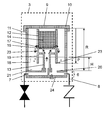
- FIG. 1 is a diagram showing a configuration of a water purification system according to Embodiment 1 of the present invention.
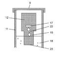
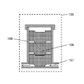
- FIG. 2 is a diagram illustrating a configuration of the solid medicine supply device according to the first embodiment of the present invention.
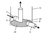
- FIG. 3 is a perspective view showing a configuration of a bottom surface and a base portion of the housing in the solid medicine supply device according to the first embodiment of the present invention.
- FIG. 4 is a diagram illustrating an example of an edge of the solid medicine supply device according to the first embodiment of the present invention.
- FIG. 5 is a diagram illustrating a more desirable shape of the edge of the solid medicine supply device according to the first embodiment of the present invention.
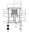
- FIG. 6 is a diagram illustrating another configuration of the solid medicine supply device according to the first embodiment of the present invention.
- FIG. 1 is a diagram showing a configuration of a water purification system according to Embodiment 1 of the present invention.
- FIG. 2 is a diagram illustrating a configuration of the solid medicine supply device according to the
- FIG. 7 is a diagram illustrating a configuration of a solid medicine supply device that is a premise of the first embodiment of the present invention.
- FIG. 8A is a perspective view illustrating another configuration of the bottom surface and the base portion of the housing in the solid medicine supply device according to the first embodiment of the present invention.
- FIG. 8B is a perspective view illustrating another configuration of the bottom surface and the base portion of the housing in the solid medicine supply device according to the first embodiment of the present invention.
- FIG. 9 is a diagram of a water purification system using a conventional drug injection device using a metering pump.
- FIG. 10 is a diagram showing a configuration of a conventional solid medicine supply device.
- the solid drug supply device is a device for supplying a solid drug while eluting a solid drug into raw water when performing a treatment of adding a disinfectant or the like to raw water (water to be treated) pumped from a well or a water tank. It is. For example, when performing iron removal treatment of well water, it is necessary to oxidize and precipitate ionic iron before filtration. In that case, it is preferable to install a solid medicine supply device in the pipe before the filtration device to oxidize the raw water.
- a connection port for connecting the solid medicine supply device is provided in the middle of the pipe, and a portion other than the connection port is sealed. Drug supply is possible.
- the water purification system 1 includes a pump 2, a solid medicine supply device 3, a filtration unit 4, and a pipe 5 connecting them.
- the solid medicine supply device 3 includes a housing 11 having a base portion 6, a bottom surface 20, and a top portion 9.
- the housing 11 is a container whose space between the bottom surface 20 and the top portion 9 has a substantially internal volume.
- the base portion 6 is provided below the bottom surface 20.
- the base 6 is provided with a water intake 7 and a drain 8.
- the water intake 7 and the drain 8 are connected to the pipe 5 outside the housing 11.
- the top 9 has a housing lid 10.
- the housing 11 includes a cylindrical container 12 and a pipe 13 inside.
- the pipe 13 connects the water intake port 7 and the bottom surface of the cylindrical container 12.
- the cylindrical container 12 is not in contact with the housing lid 10.
- the side surface of the cylindrical container 12 and the housing 11 are separated by about 1 to several centimeters.
- the conduit 13 supports the cylindrical container 12 inside the housing 11. Thereby, the cylindrical container 12 is fixed at a position higher than the center of the housing 11.
- the base portion 6 is also a portion that converts the direction of the pipe extending in the horizontal direction in the housing 11 to the vertical direction.
- a water-soluble solid drug 14 is provided in the cylindrical container 12.
- a tablet or granule is used as the water-soluble solid drug 14 a surface area can be secured and a stable solvent concentration can be maintained.
- a tablet having a diameter of 30 mm and a height of 15 mm may be used, and a granule having a diameter of 5 mm to 15 mm may be used.
- each member of the solid medicine supply device 3 may come into contact with the medicine for a long time, a material having low reactivity to the medicine such as polypropylene (PP) may be selected.
- PP polypropylene
- the pipe line 13 needs strength to support the cylindrical container 12
- vinyl chloride, ABS resin, polyethylene, or the like, which is stronger than PP, may be selected in consideration of the compatibility with the medicine.
- the outer diameter of the conduit 13 is suppressed to 5 to 1/10 or less of the inner diameter of the lower part of the housing 11, a space (water) where the solution after the supply of the medicine discharged from the discharge hole 17 is temporarily stored in the lower part of the housing 11.
- the stagnation portion 21) can be easily secured.
- a vinyl chloride tube having an outer diameter of 26 mm may be used.
- the cylindrical container 12 has a partition plate 16 inside.
- the partition plate 16 divides the inside of the cylindrical container 12 into upper and lower portions so that raw water can pass therethrough.
- the partition plate 16 can place a water-soluble solid medicine on the upper surface.
- An edge 19 having the same outer diameter as the cylindrical container 12 extends downward from the bottom surface of the cylindrical container 12.
- a discharge hole 17 penetrating the side surface of the cylindrical container 12 is provided above the partition plate 16 on the side surface of the cylindrical container 12.
- the edge portion 19 Since the edge portion 19 has a role of guiding the raw water discharged from the discharge hole 17 to the water accumulated in the housing 11, the edge portion 19 is provided below the lower portion (the lower portion 22) where the discharge hole 17 is provided. It is good to attach. It is desirable that the edge portion 19 be extended from the housing 11 without any step so that the water flows into the water retaining portion 21 smoothly.
- the edge portion 19 does not need to extend directly below the cylindrical container 12 as long as it forms a water channel from the discharge hole 17 to the base portion 6 of the housing 11, and it is about 5 degrees inward or outward. May be provided.
- the edge portion 19 does not need to extend all around, but only needs to be guided by the portion 22 below the discharge hole 17 from which the discharged water hangs. As shown in FIGS. 2 and 4, by disposing the edge portion 19 in the portion 22 below the discharge hole 17, the discharged water can smoothly flow into the water retaining portion 21 without bouncing or entrapping bubbles. Can be. As shown in FIG. 5, the shape in which the edge portion 19 is tapered toward the lower portion allows the discharged water to flow into the stagnant portion more smoothly, so that the generation of bubbles can be suppressed.
- the cylindrical container 12 When the cylindrical container 12 is formed in a cylindrical shape, it is desirable to form the lower part of the cylindrical part thinner than the upper part.
- the lower part thinner than the upper part when the lower end 23 is above the water surface, it is possible to more smoothly guide the water to the stagnant portion, so that the generation of bubbles can be suppressed.
- the partition plate 16 is a plate having a plurality of holes. Specifically, it is made of a mesh plate or a plastic plate having a plurality of holes. When the medicine to be placed is smaller than the hole of the partition plate 16, a finer PP mesh or the like may be laminated on the partition plate 16.
- the raw water flowing from the intake port 7 of the base portion 6 of the housing 11 reaches the inside of the cylindrical container 12 from the bottom surface of the cylindrical container 12 through the pipe 13. .
- the raw water flowing from the bottom of the cylindrical container 12 passes through the hole of the partition plate 16 and comes into contact with the water-soluble solid drug 14.
- the drug component is eluted into the raw water to form a drug solution.
- the drug solution is discharged from the discharge hole 17 along the upper surface of the partition plate 16 and accumulated in the lower part of the housing 11. Then, the water is supplied to the water purification system 1 from the drain port 8 of the housing 11.
- the solid medicine supply device 3 is provided with an edge 19, and the water discharged from the discharge hole 17 travels along the edge 19 and reaches the retained water 18. Therefore, no bubbles are generated and the rise in water level is suppressed. That is, it is possible to prevent the staying water from rising to the upper side of the water-soluble solid drug 14 in the cylindrical container 12 and to suppress the water-soluble solid drug 14 on the upper side from absorbing water. Thereby, the upper water-soluble solid drug 14 does not adhere to the wall surface, and the water-soluble solid drug 14 can be stably eluted.
- edge portion 19 of the present embodiment slightly protrudes as a projection, there is an effect that air bubbles are less likely to be generated as compared with the case where the edge portion 19 is not provided. As shown in FIG. 6, it is not always necessary to be immersed in the stagnant water (the lower end 23 is located above the stagnant water 18).
- the operating pressure of a general pump is about 1.1 kgf / cm 2 to 2 kgf / cm 2 , and in that case, the water level in the housing of the solid medicine supply device 3 of the present embodiment (H shown in FIG. 2) ) Is from 10% (at about 1.1 kgf / cm 2) to 60% (about 2 kg / cm 2) from the bottom of the casing in proportion to the height of the casing 11. That is, the lower end 23 of the edge 19 extends from 90% to 40% (P shown in FIG. 2) in a range (R shown in FIG.
- the lower end of the edge is set to 90% to 40% in the range (R shown in FIG. 2) from the back side of the housing lid to the bottom surface 20 in the housing. It is desirable to stretch to any position (P shown in FIG. 2).
- the bottom surface 20 of the housing 11 is also the lowest surface of the surfaces to which pressure is applied in the housing 11, that is, the bottom surface of the water retaining portion 21.
- the example of the housing 11 having the base portion 6 below the bottom surface 20 shown in FIG. 3 has been described, but the example of the housing 11 shown in FIGS. 8A and 8B may be used. That is, the base portion 6 that converts the direction of the pipe extending in the horizontal direction to the vertical direction may be exposed in the housing 11. In this case, as shown in FIG. 8A, the stagnant water 18 is also stored in the base portion 6. Only the bottom 24 of the base portion 6 becomes the bottom surface 20, and the concept of the position of the lower end 23 of the edge 19 does not change. Further, as shown in FIG. 8B, even when the drain port 8 is opened at the bottom 24, the concept of the position of the lower end 23 of the edge 19 does not change.
- the solid drug supply device is a solid drug supply device that elutes a drug into raw water supplied by a pump.
- the solid medicine supply device is provided with a water intake port and a water discharge port on a base portion, and a housing having a housing lid on the top.
- the inside of the housing is provided with a cylindrical container that partitions the inner peripheral side and the outer peripheral side of the housing, and a conduit connecting the water intake port and the bottom surface of the cylindrical container.
- the cylindrical container has a partition plate inside. The partition plate vertically divides the inside of the cylindrical container so that raw water can pass therethrough. Further, the partition plate can place a water-soluble solid drug on the upper surface.
- the side surface of the cylindrical container is provided with a discharge hole that penetrates the side surface of the cylindrical container above the partition plate.
- the bottom surface of the cylindrical container has an edge extending from the side surface of the cylindrical container.
- the lower end of the edge is extended from 90% to 40% in a range from the back side to the bottom surface of the housing lid in the housing.
- the solid medicine supply device has a peripheral portion of the cylindrical container provided with an edge portion below the discharge hole, and has a tapered shape toward the lower end.
- the solid drug supply device can stabilize the drug supply concentration, it is useful as a solid drug supply device for a small household water treatment device used for purification of well water or retained water.
Landscapes
- Chemical & Material Sciences (AREA)
- Chemical Kinetics & Catalysis (AREA)
- Life Sciences & Earth Sciences (AREA)
- Hydrology & Water Resources (AREA)
- Engineering & Computer Science (AREA)
- Environmental & Geological Engineering (AREA)
- Water Supply & Treatment (AREA)
- Organic Chemistry (AREA)
- Treatment Of Water By Oxidation Or Reduction (AREA)
Abstract
Cet appareil d'alimentation en agent chimique solide est un appareil dans lequel un agent chimique est élué dans l'eau brute fournie par une pompe. L'appareil d'alimentation en agent chimique solide possède un orifice d'admission d'eau et un orifice d'évacuation d'eau dans une partie de base, et possède un boîtier ayant un couvercle de boîtier et disposé dans une partie supérieure de l'appareil. Un récipient cylindrique qui divise le boîtier en un côté circonférentiel interne et un côté circonférentiel externe, et un conduit qui relie l'orifice d'admission d'eau et la surface inférieure du récipient cylindrique sont aménagés à l'intérieur du boîtier. Le récipient cylindrique comporte une paroi de séparation. La paroi de séparation sépare l'intérieur du récipient cylindrique en parties supérieure et inférieure, et permet à l'eau brute de traverser. Un produit chimique solide hydrosoluble peut être placé sur la surface supérieure de la paroi de séparation. Un orifice d'évacuation traversant la surface latérale du récipient cylindrique est aménagé sur la surface latérale du récipient cylindrique de façon à se trouver au-dessus de la paroi de séparation. Une partie de bord s'étendant à partir de la surface latérale du récipient cylindrique est aménagée sur la surface inférieure du récipient cylindrique. L'appareil d'alimentation en agent chimique solide, dans lequel un agent chimique peut être élué de façon stable même après une utilisation à long terme, peut être incorporé dans un système de traitement d'eau.
Applications Claiming Priority (2)
| Application Number | Priority Date | Filing Date | Title |
|---|---|---|---|
| JP2018-125687 | 2018-07-02 | ||
| JP2018125687 | 2018-07-02 |
Publications (1)
| Publication Number | Publication Date |
|---|---|
| WO2020008967A1 true WO2020008967A1 (fr) | 2020-01-09 |
Family
ID=69059608
Family Applications (1)
| Application Number | Title | Priority Date | Filing Date |
|---|---|---|---|
| PCT/JP2019/025286 Ceased WO2020008967A1 (fr) | 2018-07-02 | 2019-06-26 | Appareil d'alimentation en agent chimique solide |
Country Status (1)
| Country | Link |
|---|---|
| WO (1) | WO2020008967A1 (fr) |
Citations (5)
| Publication number | Priority date | Publication date | Assignee | Title |
|---|---|---|---|---|
| US3145087A (en) * | 1961-05-22 | 1964-08-18 | Walker Alexander Marriott | Feeders for dissolving chemicals into intermittent flow fluid systems |
| US3864090A (en) * | 1973-10-12 | 1975-02-04 | Kenneth Richards | Pressure-type tablet hypochlorinating device |
| US5384102A (en) * | 1993-07-28 | 1995-01-24 | Ppg Industries, Inc. | Chemical feeder |
| JP2010195490A (ja) * | 2001-12-04 | 2010-09-09 | Arch Chemicals Inc | 薬品供給装置 |
| US20160016832A1 (en) * | 2014-07-15 | 2016-01-21 | Axiall Ohio Inc. | Chemical Feeder |
-
2019
- 2019-06-26 WO PCT/JP2019/025286 patent/WO2020008967A1/fr not_active Ceased
Patent Citations (5)
| Publication number | Priority date | Publication date | Assignee | Title |
|---|---|---|---|---|
| US3145087A (en) * | 1961-05-22 | 1964-08-18 | Walker Alexander Marriott | Feeders for dissolving chemicals into intermittent flow fluid systems |
| US3864090A (en) * | 1973-10-12 | 1975-02-04 | Kenneth Richards | Pressure-type tablet hypochlorinating device |
| US5384102A (en) * | 1993-07-28 | 1995-01-24 | Ppg Industries, Inc. | Chemical feeder |
| JP2010195490A (ja) * | 2001-12-04 | 2010-09-09 | Arch Chemicals Inc | 薬品供給装置 |
| US20160016832A1 (en) * | 2014-07-15 | 2016-01-21 | Axiall Ohio Inc. | Chemical Feeder |
Similar Documents
| Publication | Publication Date | Title |
|---|---|---|
| JP5362343B2 (ja) | 膜分離ユニット | |
| AU644924B2 (en) | Chemical feed apparatus | |
| US8945377B2 (en) | Installation-free water purifying device | |
| WO2018014383A1 (fr) | Distributeur d'eau pour les animaux et son procédé d'alimentation en eau | |
| TW201714837A (zh) | 水處理系統 | |
| JP4695703B2 (ja) | 体外循環回路用チャンバ | |
| US9266757B2 (en) | Chemical feeder | |
| CN101535190B (zh) | 水净化装置 | |
| JP2008237996A (ja) | 微細気泡発生装置及びそれを用いた洗浄装置、シャワリング装置、生簀 | |
| WO2020008967A1 (fr) | Appareil d'alimentation en agent chimique solide | |
| JP2008012512A (ja) | 水オゾン混合装置、水浄化装置、オゾン水生成装置、気液混合器および逆止弁 | |
| CN111094193A (zh) | 水处理装置及水处理系统 | |
| JP2019147144A (ja) | 固形薬剤供給装置 | |
| WO2019167552A1 (fr) | Dispositif d'alimentation en produit chimique | |
| JP4392416B2 (ja) | 散気装置用拡散機、及び散気装置 | |
| JP2019166497A (ja) | 固形薬剤供給装置 | |
| JP2020032360A (ja) | 固形薬剤供給装置 | |
| JP2009119338A (ja) | 加圧浮上装置 | |
| CN210176634U (zh) | 一种化验室废水处理设备 | |
| JP6032100B2 (ja) | 散気装置および水処理装置 | |
| JP2019171260A (ja) | 固形薬剤供給装置 | |
| CN102580175A (zh) | 自动防回血输液器 | |
| CN208199702U (zh) | 一种滤料投放装置 | |
| JP2020168219A (ja) | シャワーヘッド | |
| WO2020004208A1 (fr) | Module de membranes à fibres creuses et procédé de nettoyage de celui-ci |
Legal Events
| Date | Code | Title | Description |
|---|---|---|---|
| 121 | Ep: the epo has been informed by wipo that ep was designated in this application |
Ref document number: 19830537 Country of ref document: EP Kind code of ref document: A1 |
|
| NENP | Non-entry into the national phase |
Ref country code: DE |
|
| 122 | Ep: pct application non-entry in european phase |
Ref document number: 19830537 Country of ref document: EP Kind code of ref document: A1 |
|
| NENP | Non-entry into the national phase |
Ref country code: JP |