WO2020008971A1 - Lampe à excimère - Google Patents
Lampe à excimère Download PDFInfo
- Publication number
- WO2020008971A1 WO2020008971A1 PCT/JP2019/025322 JP2019025322W WO2020008971A1 WO 2020008971 A1 WO2020008971 A1 WO 2020008971A1 JP 2019025322 W JP2019025322 W JP 2019025322W WO 2020008971 A1 WO2020008971 A1 WO 2020008971A1
- Authority
- WO
- WIPO (PCT)
- Prior art keywords
- discharge vessel
- auxiliary electrode
- flat
- excimer lamp
- electrode
- Prior art date
- Legal status (The legal status is an assumption and is not a legal conclusion. Google has not performed a legal analysis and makes no representation as to the accuracy of the status listed.)
- Ceased
Links
Images



Classifications
-
- H—ELECTRICITY
- H01—ELECTRIC ELEMENTS
- H01J—ELECTRIC DISCHARGE TUBES OR DISCHARGE LAMPS
- H01J65/00—Lamps without any electrode inside the vessel; Lamps with at least one main electrode outside the vessel
-
- H—ELECTRICITY
- H01—ELECTRIC ELEMENTS
- H01J—ELECTRIC DISCHARGE TUBES OR DISCHARGE LAMPS
- H01J65/00—Lamps without any electrode inside the vessel; Lamps with at least one main electrode outside the vessel
- H01J65/04—Lamps in which a gas filling is excited to luminesce by an external electromagnetic field or by external corpuscular radiation, e.g. for indicating plasma display panels
- H01J65/042—Lamps in which a gas filling is excited to luminesce by an external electromagnetic field or by external corpuscular radiation, e.g. for indicating plasma display panels by an external electromagnetic field
- H01J65/046—Lamps in which a gas filling is excited to luminesce by an external electromagnetic field or by external corpuscular radiation, e.g. for indicating plasma display panels by an external electromagnetic field the field being produced by using capacitive means around the vessel
-
- H—ELECTRICITY
- H01—ELECTRIC ELEMENTS
- H01J—ELECTRIC DISCHARGE TUBES OR DISCHARGE LAMPS
- H01J61/00—Gas-discharge or vapour-discharge lamps
- H01J61/02—Details
- H01J61/04—Electrodes; Screens; Shields
- H01J61/06—Main electrodes
- H01J61/067—Main electrodes for low-pressure discharge lamps
- H01J61/0672—Main electrodes for low-pressure discharge lamps characterised by the construction of the electrode
-
- H—ELECTRICITY
- H01—ELECTRIC ELEMENTS
- H01J—ELECTRIC DISCHARGE TUBES OR DISCHARGE LAMPS
- H01J61/00—Gas-discharge or vapour-discharge lamps
- H01J61/02—Details
- H01J61/12—Selection of substances for gas fillings; Specified operating pressure or temperature
-
- H—ELECTRICITY
- H01—ELECTRIC ELEMENTS
- H01J—ELECTRIC DISCHARGE TUBES OR DISCHARGE LAMPS
- H01J61/00—Gas-discharge or vapour-discharge lamps
- H01J61/02—Details
- H01J61/30—Vessels; Containers
- H01J61/302—Vessels; Containers characterised by the material of the vessel
-
- H—ELECTRICITY
- H01—ELECTRIC ELEMENTS
- H01J—ELECTRIC DISCHARGE TUBES OR DISCHARGE LAMPS
- H01J61/00—Gas-discharge or vapour-discharge lamps
- H01J61/02—Details
- H01J61/30—Vessels; Containers
- H01J61/305—Flat vessels or containers
-
- H—ELECTRICITY
- H01—ELECTRIC ELEMENTS
- H01J—ELECTRIC DISCHARGE TUBES OR DISCHARGE LAMPS
- H01J61/00—Gas-discharge or vapour-discharge lamps
- H01J61/02—Details
- H01J61/30—Vessels; Containers
- H01J61/33—Special shape of cross-section, e.g. for producing cool spot
-
- H—ELECTRICITY
- H01—ELECTRIC ELEMENTS
- H01J—ELECTRIC DISCHARGE TUBES OR DISCHARGE LAMPS
- H01J61/00—Gas-discharge or vapour-discharge lamps
- H01J61/02—Details
- H01J61/36—Seals between parts of vessels; Seals for leading-in conductors; Leading-in conductors
- H01J61/366—Seals for leading-in conductors
- H01J61/368—Pinched seals or analogous seals
-
- H—ELECTRICITY
- H01—ELECTRIC ELEMENTS
- H01J—ELECTRIC DISCHARGE TUBES OR DISCHARGE LAMPS
- H01J5/00—Details relating to vessels or to leading-in conductors common to two or more basic types of discharge tubes or lamps
- H01J5/50—Means forming part of the tube or lamps for the purpose of providing electrical connection to it
- H01J5/52—Means forming part of the tube or lamps for the purpose of providing electrical connection to it directly applied to or forming part of the vessel
-
- H—ELECTRICITY
- H01—ELECTRIC ELEMENTS
- H01J—ELECTRIC DISCHARGE TUBES OR DISCHARGE LAMPS
- H01J61/00—Gas-discharge or vapour-discharge lamps
- H01J61/02—Details
- H01J61/12—Selection of substances for gas fillings; Specified operating pressure or temperature
- H01J61/16—Selection of substances for gas fillings; Specified operating pressure or temperature having helium, argon, neon, krypton, or xenon as the principle constituent
Definitions
- the present invention relates to an excimer lamp provided with a discharge vessel having a flat rectangular cross section, and more particularly to an excimer lamp having an electrode provided on an outer surface of the discharge vessel.
- Excimer lamps can emit ultraviolet light, particularly ultraviolet light having a short wavelength, and are therefore used in semiconductor manufacturing processes, liquid crystal manufacturing processes, ozone generators, and the like.
- Patent Document 1 discloses an example of such an excimer lamp.
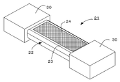
- An excimer lamp 21 according to FIG. 5 is shown.
- the discharge vessel 22 has a flat rectangular cross section as a whole, and an external electrode 24 faces an outer surface of a flat portion 23 of the discharge vessel 22. These external electrodes 24 are connected to a high-frequency power supply (not shown).
- the discharge vessel 22 is made of, for example, a material having excellent transparency to ultraviolet light having a wavelength of 200 nm or less, for example, silica glass such as synthetic quartz glass, sapphire glass, or the like.
- a rare gas such as xenon gas or krypton gas, or a mixed gas of these with a halogen gas such as chlorine is filled in the discharge vessel 22 as a luminescent gas depending on the wavelength of light used.
- lamp bases 30, 30 for fixing the excimer lamp 21 to the light irradiation device are attached.
- the structure of the excimer lamp 21 is disclosed, for example, in Japanese Patent Application Laid-Open No. 2013-149546 (Patent Document 2), and the specific structure is shown in FIG.
- the discharge vessel 22 includes a glass tube 221 having a flat rectangular cross-sectional shape, and a sealing member 222 inserted and welded to both ends thereof.
- the sealing member 222 is provided with an exhaust pipe 223. At this time, the sealing member 222 is inserted and welded to the inside by a small amount from the end of the glass tube 221, and the end of the glass tube 221 has a skirt 224 protruding outward from the sealing member 222.
- a solid electrode 25 is provided at an end of the external electrode 24, and a lead wire 26 for supplying power to the external electrode 24 is provided on the solid electrode 25. It is connected by welding. Then, as shown in FIG. 6B, a lamp base 30 is attached so as to cover the end of the discharge vessel 22.
- the power supply lead wire 26 is welded and connected to the external electrode 24 (the solid electrode 25 thereof) by the glass solder 27, so that the thickness direction of the discharge vessel 22 (the thickness between the external electrodes)
- the welded portion (solder) 27 protrudes from the outer surface in the direction (direction)
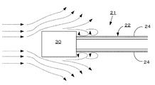
- the thickness of the lamp base 30 becomes considerably larger than the thickness of the discharge vessel 22, thereby causing further problems.
- Vacuum ultraviolet light from an excimer lamp has a short range in a gas, and is absorbed and attenuated by surrounding gases. Even when such an excimer lamp is used as a light source for directly irradiating an object to be processed with vacuum ultraviolet light other than the gas treatment, the excimer lamp is not treated because the lamp base is considerably thicker than the lamp. There is also a drawback that the device cannot be placed close to the object and effective irradiation of ultraviolet light cannot be performed.
- An object of the present invention is to provide a discharge vessel having a flat, substantially rectangular cross-sectional shape, comprising a pair of flat portions and a pair of side portions, in consideration of the above-described problems of the related art.
- the thickness of the lamp base provided at the end of the discharge vessel is made as small as possible to enable effective irradiation of the object to be treated with ultraviolet light.
- An object of the present invention is to provide an excimer lamp suitable for an apparatus for processing by circulating in the longitudinal direction of the lamp.
- an auxiliary electrode is provided at an end of the external electrode to extend to a region smaller than a distance between the flat portions, and a lead wire for supplying power to the external electrode is provided.
- the discharge vessel comprises a flat glass tube having a substantially rectangular cross-sectional shape, and a sealing member welded in the vicinity of the end thereof, and the end of the glass tube protrudes outward from the sealing member and has a hem.
- a concave portion is formed in a plane portion of the skirt portion in a direction facing the external electrode, the auxiliary electrode extends to the concave portion, and the lead wire is connected to the auxiliary electrode in the concave portion. It is characterized by having. Further, a pinch seal portion is formed at an end of the discharge vessel to seal the discharge vessel, the auxiliary electrode extends to the pinch seal portion, and the lead wire is connected to the auxiliary electrode at the pinch seal portion. It is characterized by being connected.
- the auxiliary electrode is provided at the end of the external electrode, and in a region smaller than the distance between the external electrodes, a lead wire for supplying power to the external electrode is connected to the auxiliary electrode.
- the lead wire and its welded portion do not protrude more in the thickness direction than the flat portion, and the lamp base covering the same can be prevented from protruding beyond the thickness of the discharge vessel as much as possible. The flow can smoothly flow along the discharge vessel of the lamp without obstruction, and effective processing can be performed.
- the lamp and the object to be processed can be arranged close to each other, so that the attenuation of the vacuum ultraviolet light by air can be suppressed and effective processing can be performed.
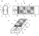
- FIG. 2 is a top view (A), a side view (B), and a perspective view (C) of the first embodiment of the present invention.
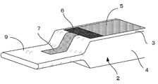
- FIG. 7 is a perspective view of a second embodiment of the present invention.
- FIG. 9 is a perspective view of a conventional excimer lamp.
- FIG. 4 is an explanatory view of a problem of a conventional excimer lamp.
- FIG. 1 shows an excimer lamp 1 of the present invention
- FIG. 2 shows a state where lead wires are connected. 1 and 2, the exhaust pipe (see FIG. 6) is omitted in order to avoid complication.
- the excimer lamp 1 has a discharge vessel 2 having a flat, substantially rectangular cross-sectional shape including a pair of rectangular flat portions 3, 3 and a pair of side portions 4, 4 along side edges in the longitudinal direction. .
- a pair of external electrodes 5, 5 are provided on the outer surfaces of the flat portions 3, 3 of the discharge vessel 2.
- the discharge space inside the discharge vessel 2 is filled with rare gas and chlorine gas as discharge gas.
- the noble gas is selected from krypton, xenon and the like.
- the external electrodes 5 and 5 can be formed on the outer surfaces of the flat portions 3 and 3 of the discharge vessel 2, for example, by applying a metal paste such as gold or pasting transfer paper.
- the external electrode 5 is formed, for example, in a net shape so that at least one of the electrodes has a light transmitting portion, and the ultraviolet light generated in the discharge space is emitted through the light transmitting portion.
- a so-called solid electrode 6 is formed at one end of the external electrode 5.
- the cross-sectional shape of the discharge vessel 2 does not need to be exactly a flat rectangular shape, and the flat portion 3 and / or the side surface portion 4 may have a shape slightly bulging to the outside, or conversely. The shape may be concave toward the inside. Furthermore, a trapezoidal shape or a parallelogram shape can also be adopted, and in the present specification, these are collectively referred to as a substantially rectangular shape.
- the discharge vessel 2 is composed of a cylindrical glass tube 2a having a substantially flat rectangular cross section and a sealing member 2b welded to the vicinity of the end of the tube 2a.
- a skirt portion 2c is formed to protrude outward from the sealing member 2b.
- concave portions 8 are formed in the skirt portion 2c in a direction facing the external electrodes 5.
- An auxiliary electrode 7 is connected to the external electrode 5 (solid electrode 6) and extends to the recess 8.
- the auxiliary electrode 7 may be formed by printing, or may be formed by applying a conductive paste with a dispenser and drying.
- a lead wire 10 for supplying power to the external electrode 5 is welded to the auxiliary electrode 7 in the recess 8 by a glass solder 11 or the like. At this time, it is preferable that the glass solder 11 fits on the upper surface of the recess 8, that is, at a position lower than the plane portion 3.
- FIGS. 3 and 4 show another second embodiment, wherein a pinch seal portion 9 crushed in the direction of the flat portion 3 is formed at the end of the discharge vessel 2.
- the pinch seal portion 9 is formed by heating and softening the end of the discharge vessel 2 and pressing and crushing the end, whereby the discharge vessel 2 is sealed.
- An auxiliary electrode 7 is connected to the solid electrode 6 at the end of the external electrode 5 provided on the flat portion 3 of the discharge vessel 2, and the auxiliary electrode 7 is pinched along the outer surface of the discharge vessel 2. It extends to the seal portion 9.
- 4A and 4B show a connection structure of a lead wire 10 for supplying power to the external electrode 5, and the lead wire 10 is welded to the auxiliary electrode 7 on the pinch seal portion 9 by a glass solder 11 or the like. It is connected.
- the welded portion (glass solder) 11 has a thickness between the flat portions 3 of the discharge vessel 2.
- the lamp base does not protrude greatly in the vertical direction, and in some cases, can be accommodated in the range in the thickness direction. Even if a lamp base (see FIG. 6B) is attached to this end, the thickness can be reduced. And the thickness between the flat portions 3, 3 does not greatly exceed the thickness between the flat portions 3, 3.
- the auxiliary electrode 7 is shown to have a width smaller than that of the external electrode 5. However, the auxiliary electrode 7 may have the same width as the external electrode 5 without being particularly narrow. Further, in the embodiments of FIGS. 1 and 2 and the embodiments of FIGS. 3 and 4, the solid electrode 6 is provided at the end of the external electrode 5, but a structure in which the solid electrode 6 is omitted may be employed.
- the auxiliary electrode is provided at the end of the external electrode provided on the flat portion of the discharge vessel, and the lead wire is connected to the auxiliary electrode in a region smaller than the distance between the external electrodes.
- the lead wire and its welded portion do not protrude more in the thickness direction than the flat portion, and the lamp base covering the same can be prevented from protruding more than the thickness of the discharge vessel as much as possible. Is played.
Landscapes
- Physics & Mathematics (AREA)
- Engineering & Computer Science (AREA)
- Plasma & Fusion (AREA)
- Electromagnetism (AREA)
- Vessels And Coating Films For Discharge Lamps (AREA)
Abstract
Dans la lampe à excimère selon la présente invention, un récipient à décharge plate ayant une section transversale sensiblement rectangulaire et comprenant une paire de parties planes et une paire de parties de surface latérale comporte une paire d'électrodes externes disposées sur les surfaces externes respectives des parties planes. Les parties d'extrémité des électrodes externes sont pourvues d'une électrode auxiliaire s'étendant jusqu'à une région qui est rendue plus petite que la distance entre les parties planes. Un fil qui fournit de l'électricité à l'électrode externe est connecté à l'électrode auxiliaire dans la région qui est rendue plus petite que la distance entre les parties planes.
Priority Applications (3)
| Application Number | Priority Date | Filing Date | Title |
|---|---|---|---|
| US17/257,268 US11328923B2 (en) | 2018-07-06 | 2019-06-26 | Excimer lamp |
| CN201980035910.4A CN112204704B (zh) | 2018-07-06 | 2019-06-26 | 准分子灯 |
| US17/736,279 US11569083B2 (en) | 2018-07-06 | 2022-05-04 | Excimer lamp |
Applications Claiming Priority (2)
| Application Number | Priority Date | Filing Date | Title |
|---|---|---|---|
| JP2018-129309 | 2018-07-06 | ||
| JP2018129309A JP7029641B2 (ja) | 2018-07-06 | 2018-07-06 | エキシマランプ |
Related Child Applications (2)
| Application Number | Title | Priority Date | Filing Date |
|---|---|---|---|
| US17/257,268 A-371-Of-International US11328923B2 (en) | 2018-07-06 | 2019-06-26 | Excimer lamp |
| US17/736,279 Continuation US11569083B2 (en) | 2018-07-06 | 2022-05-04 | Excimer lamp |
Publications (1)
| Publication Number | Publication Date |
|---|---|
| WO2020008971A1 true WO2020008971A1 (fr) | 2020-01-09 |
Family
ID=69059610
Family Applications (1)
| Application Number | Title | Priority Date | Filing Date |
|---|---|---|---|
| PCT/JP2019/025322 Ceased WO2020008971A1 (fr) | 2018-07-06 | 2019-06-26 | Lampe à excimère |
Country Status (5)
| Country | Link |
|---|---|
| US (2) | US11328923B2 (fr) |
| JP (1) | JP7029641B2 (fr) |
| CN (1) | CN112204704B (fr) |
| TW (1) | TW202006782A (fr) |
| WO (1) | WO2020008971A1 (fr) |
Families Citing this family (1)
| Publication number | Priority date | Publication date | Assignee | Title |
|---|---|---|---|---|
| CN115763193A (zh) * | 2022-11-02 | 2023-03-07 | 星际光(上海)实业有限公司 | 电极形成方法、装置及dbd准分子灯 |
Citations (5)
| Publication number | Priority date | Publication date | Assignee | Title |
|---|---|---|---|---|
| JP2003317665A (ja) * | 2002-04-18 | 2003-11-07 | Sanshin Denki Kk | 冷陰極放電管 |
| JP2010009939A (ja) * | 2008-06-26 | 2010-01-14 | Gs Yuasa Corporation | 放電ランプ |
| JP2011023156A (ja) * | 2009-07-14 | 2011-02-03 | Ushio Inc | エキシマランプ |
| JP2012164531A (ja) * | 2011-02-07 | 2012-08-30 | Ushio Inc | エキシマランプ |
| JP2015197948A (ja) * | 2014-03-31 | 2015-11-09 | 株式会社Gsユアサ | 放電ランプ及びこの放電ランプを用いた光照射装置 |
Family Cites Families (11)
| Publication number | Priority date | Publication date | Assignee | Title |
|---|---|---|---|---|
| JP2003317666A (ja) * | 2002-04-18 | 2003-11-07 | Sanshin Denki Kk | 冷陰極放電管の組み合わせ構造 |
| JP2005347025A (ja) * | 2004-06-01 | 2005-12-15 | Japan Storage Battery Co Ltd | 誘電体バリア放電ランプ |
| JP5074248B2 (ja) * | 2008-03-14 | 2012-11-14 | 株式会社オーク製作所 | エキシマランプ |
| TWI437609B (zh) * | 2008-05-30 | 2014-05-11 | Gs Yuasa Int Ltd | 外部電極型放電燈以及使用該放電燈之紫外線照射裝置 |
| JP5051042B2 (ja) * | 2008-07-29 | 2012-10-17 | ウシオ電機株式会社 | エキシマランプ |
| JP2012109389A (ja) * | 2010-11-17 | 2012-06-07 | Ushio Inc | エキシマ光照射装置 |
| JP2013098015A (ja) | 2011-11-01 | 2013-05-20 | Ushio Inc | 紫外線照射装置 |
| JP5891804B2 (ja) | 2012-01-23 | 2016-03-23 | ウシオ電機株式会社 | エキシマランプ |
| JP5888256B2 (ja) * | 2013-02-06 | 2016-03-16 | ウシオ電機株式会社 | エキシマランプ |
| JP2014195758A (ja) * | 2013-03-29 | 2014-10-16 | ウシオ電機株式会社 | ガス処理装置 |
| JP2017120699A (ja) * | 2015-12-28 | 2017-07-06 | ウシオ電機株式会社 | 高周波用導線および高周波点灯型光源装置 |
-
2018
- 2018-07-06 JP JP2018129309A patent/JP7029641B2/ja active Active
-
2019
- 2019-04-10 TW TW108112439A patent/TW202006782A/zh unknown
- 2019-06-26 US US17/257,268 patent/US11328923B2/en active Active
- 2019-06-26 WO PCT/JP2019/025322 patent/WO2020008971A1/fr not_active Ceased
- 2019-06-26 CN CN201980035910.4A patent/CN112204704B/zh active Active
-
2022
- 2022-05-04 US US17/736,279 patent/US11569083B2/en active Active
Patent Citations (5)
| Publication number | Priority date | Publication date | Assignee | Title |
|---|---|---|---|---|
| JP2003317665A (ja) * | 2002-04-18 | 2003-11-07 | Sanshin Denki Kk | 冷陰極放電管 |
| JP2010009939A (ja) * | 2008-06-26 | 2010-01-14 | Gs Yuasa Corporation | 放電ランプ |
| JP2011023156A (ja) * | 2009-07-14 | 2011-02-03 | Ushio Inc | エキシマランプ |
| JP2012164531A (ja) * | 2011-02-07 | 2012-08-30 | Ushio Inc | エキシマランプ |
| JP2015197948A (ja) * | 2014-03-31 | 2015-11-09 | 株式会社Gsユアサ | 放電ランプ及びこの放電ランプを用いた光照射装置 |
Also Published As
| Publication number | Publication date |
|---|---|
| TW202006782A (zh) | 2020-02-01 |
| US11569083B2 (en) | 2023-01-31 |
| US20220262617A1 (en) | 2022-08-18 |
| US20210272792A1 (en) | 2021-09-02 |
| JP2020009621A (ja) | 2020-01-16 |
| CN112204704B (zh) | 2024-06-04 |
| US11328923B2 (en) | 2022-05-10 |
| CN112204704A (zh) | 2021-01-08 |
| JP7029641B2 (ja) | 2022-03-04 |
Similar Documents
| Publication | Publication Date | Title |
|---|---|---|
| JP5074248B2 (ja) | エキシマランプ | |
| KR20090097103A (ko) | 엑시머 램프 및 그 엑시머 램프의 제조 방법 | |
| WO2020008971A1 (fr) | Lampe à excimère | |
| JP6921557B2 (ja) | 放電ランプおよびその製造方法 | |
| CN101031993B (zh) | 紫外线灯及紫外线照射装置 | |
| JP7155481B2 (ja) | 放電ランプおよびオゾン生成方法 | |
| JP6398839B2 (ja) | 光源装置 | |
| CN101711083B (zh) | 点灯装置 | |
| JP7132540B2 (ja) | エキシマランプ | |
| CN100562970C (zh) | 介质阻挡放电灯以及紫外线照射装置 | |
| JP2021051936A (ja) | バリア放電ランプおよび紫外線照射ユニット | |
| JP3744397B2 (ja) | 紫外線照射器 | |
| JP2025117773A (ja) | 紫外線照射装置 | |
| JP2021197267A (ja) | 紫外線照射装置 | |
| JP2021051937A (ja) | バリア放電ランプおよび紫外線照射ユニット | |
| JP2021197268A (ja) | 紫外線照射装置 | |
| JP4573027B2 (ja) | エキシマランプ点灯装置 | |
| JP7545116B2 (ja) | 紫外線照射装置 | |
| JP7459673B2 (ja) | 紫外線照射装置 | |
| TWI790362B (zh) | 紫外線照射單元、紫外線照射裝置及屏蔽放電燈 | |
| TWI809175B (zh) | 阻擋放電燈 | |
| JP6915352B2 (ja) | エキシマランプおよび光照射装置 | |
| JP2021197269A (ja) | 紫外線照射装置 | |
| JP2008053014A (ja) | 光照射装置 | |
| JP2021112723A (ja) | 光照射装置、および処理装置 |
Legal Events
| Date | Code | Title | Description |
|---|---|---|---|
| 121 | Ep: the epo has been informed by wipo that ep was designated in this application |
Ref document number: 19831253 Country of ref document: EP Kind code of ref document: A1 |
|
| NENP | Non-entry into the national phase |
Ref country code: DE |
|
| 122 | Ep: pct application non-entry in european phase |
Ref document number: 19831253 Country of ref document: EP Kind code of ref document: A1 |