WO2020008983A1 - Procédé de fabrication de produit alimentaire emballé et d'obturateur - Google Patents
Procédé de fabrication de produit alimentaire emballé et d'obturateur Download PDFInfo
- Publication number
- WO2020008983A1 WO2020008983A1 PCT/JP2019/025485 JP2019025485W WO2020008983A1 WO 2020008983 A1 WO2020008983 A1 WO 2020008983A1 JP 2019025485 W JP2019025485 W JP 2019025485W WO 2020008983 A1 WO2020008983 A1 WO 2020008983A1
- Authority
- WO
- WIPO (PCT)
- Prior art keywords
- convergence point
- shutter
- shutter piece
- molding surface
- rim
- Prior art date
- Legal status (The legal status is an assumption and is not a legal conclusion. Google has not performed a legal analysis and makes no representation as to the accuracy of the status listed.)
- Ceased
Links
Images





Classifications
-
- A—HUMAN NECESSITIES
- A21—BAKING; EDIBLE DOUGHS
- A21C—MACHINES OR EQUIPMENT FOR MAKING OR PROCESSING DOUGHS; HANDLING BAKED ARTICLES MADE FROM DOUGH
- A21C11/00—Other machines for forming the dough into its final shape before cooking or baking
- A21C11/10—Other machines for forming the dough into its final shape before cooking or baking combined with cutting apparatus
-
- A—HUMAN NECESSITIES
- A23—FOODS OR FOODSTUFFS; TREATMENT THEREOF, NOT COVERED BY OTHER CLASSES
- A23P—SHAPING OR WORKING OF FOODSTUFFS, NOT FULLY COVERED BY A SINGLE OTHER SUBCLASS
- A23P20/00—Coating of foodstuffs; Coatings therefor; Making laminated, multi-layered, stuffed or hollow foodstuffs
- A23P20/20—Making of laminated, multi-layered, stuffed or hollow foodstuffs, e.g. by wrapping in preformed edible dough sheets or in edible food containers
Definitions
- the following disclosure relates to a method for producing an encased food product by squeezing a food dough, and a shutter or shutter device therefor.
- the production of the wrapped food is, for example, by squeezing the dough of the food, which has been previously made into an appropriate amount, or by squeezing and cutting the continuously fed dough at appropriate intervals.
- Such a process may be performed in a state where the dough is discharged from the nozzle and hung, or may be performed in a state where the dough is placed on a table. In some cases, it is transported horizontally by a conveyor or the like and used in a process.
- Patent Documents 1 to 3 disclose related technologies.
- a method of manufacturing wrapped food includes a method of forming, on a plurality of spindles symmetrically arranged around a convergence point, a molding surface facing the convergence point and a molding surface of an adjacent shutter piece. Movably supports a plurality of shutter pieces each including an opposing surface slidably in contact with the front surface, a tip between the molding surface and the opposing surface, and a rim portion opposite to the convergence point. Surrounding the opening around the convergence point in contact with each other, allowing the dough of the wrapped food to be positioned within the opening, causing an endless shrinkable member to wrap around the rim, and moving toward the convergence point.
- the rim portions each have an offset from a straight line connecting the convergence point and the support shaft, so that the pressing force is respectively The support shaft so that the tip is directed to the convergence point And which can be rotated the shutter piece around.
- the shutter device includes a plurality of support shafts symmetrically arranged around the convergence point, and a plurality of support shafts movably supported by the support shafts and in contact with each other, and surrounding the opening around the convergence point.
- a shutter piece a molding surface in which each shutter piece faces the convergence point, a facing surface slidably in contact with a molding surface of an adjacent shutter piece, and a tip between the molding surface and the facing surface.
- a plurality of shutter pieces comprising a rim portion facing away from the convergence point, and circling around the rim portion to exert a pressing force on the rim portion toward the convergence point;
- An endless contractile member wherein the rim portion has an offset from a straight line connecting the convergence point and the support shaft, so that the pressing force moves the tip to the convergence point.
- the shutter piece around the support shaft so that And which can be rotated.
- each of the plurality of support shafts symmetrically arranged around the convergence point is movably supported, contacts each other, surrounds the opening around the convergence point, and receives the pressing force of the endless contractible member.
- the plurality of shutter pieces that converge toward the convergence point and close the opening are arranged such that each shutter piece slidably contacts a molding surface facing the convergence point and a molding surface of an adjacent shutter piece. Surface, a tip between the molding surface and the facing surface, and a rim portion facing away from the convergence point, wherein the rim portion is formed by a straight line connecting the convergence point and the support shaft.
- There is an offset so that each of the pressing forces causes the shutter piece to rotate about the support shaft such that the tip is directed toward the convergence point.
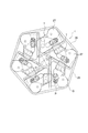
- FIG. 1 is a plan view of the shutter device, showing a state where a plurality of shutter pieces are at an initial position before converging.
- FIG. 2 is a plan view of the shutter device, showing a state where the shutter device slightly converges from the state of FIG.
- FIG. 3 is a plan view of the shutter device, showing a state in which the shutter device is further converged from the state of FIG.
- FIG. 4 is a plan view of the shutter device, showing a state where a plurality of shutter pieces are completely converged.
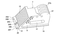
- FIG. 5 is a perspective view of the shutter piece.
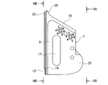
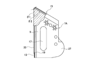
- FIG. 6 is a plan view of the shutter piece.
- FIG. 7 is a side view of the shutter strip taken from line VII-VII of FIG. FIG.
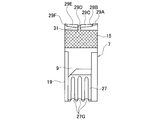
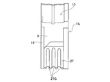
- FIG. 8 is a side view of the shutter strip taken from line VIII-VIII of FIG.
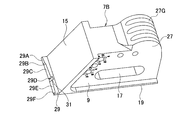
- FIG. 9 is a perspective view of a shutter piece according to another embodiment.
- FIG. 10 is a plan view of a shutter piece according to another embodiment.
- FIG. 11 is a side view of a shutter piece according to another embodiment, and is a view corresponding to FIG.
- FIG. 12 is a perspective view of a shutter piece according to still another embodiment.
- the manufacturing method, shutter device, and shutter piece of the wrapped food disclosed below can be applied to any known wrapped food manufacturing apparatus. Details of known devices will not be described.
- a shutter device 1 includes a plurality of support shafts 3. These support shafts 3 are located at the vertices of the regular polygon, respectively, and the center of the regular polygon coincides with the convergence point O of the shutter. Alternatively, these support shafts 3 are arranged symmetrically around the convergence point O.
- An actuator for rotating each of the support shafts 3 around the support shaft 3 may be connected to the support shaft 3.
- a plurality of actuators may be connected to each support shaft 3, or one actuator may be connected to each support shaft 3 by a belt, a gear mechanism, or the like. In any case, the support shaft 3 rotates in the same direction in synchronization.
- Each support shaft 3 includes a guide portion 5 slightly extending in a direction orthogonal to the respective axial directions.
- Each guide part 5 is fitted into a long hole 17 described later, and transmits the rotation of the support shaft 3 to the shutter piece 7.
- the guide portion 5 may be an appropriate structure such as a prism or a rectangular body that fits into the elongated hole 17.
- the plurality of shutter pieces 7 are each supported by the support shaft 3 and are movable in a direction orthogonal to the axial direction of the support shaft 3 (typically, along the guide portion 5).
- the plurality of shutter pieces 7 are arranged so as to be in contact with each other, and thus surround the opening 11 around the convergence point O.
- the number of the shutter pieces 7 is six in the illustrated example, but may be an arbitrary number of three or more.
- the food dough is conveyed or hung so as to be located in the opening 11, and the shutter pieces 7 converge while sliding with each other, whereby the dough is squeezed and cut.
- Each shutter piece 7 includes a main body 9, which is not essential but extends, for example, in the longitudinal direction thereof, and further includes a molding surface 13 on the side of the main body 9 facing the convergence point O.
- the molding surface 13 is a surface surrounding the opening 11 and a surface for contacting and molding the fabric and cutting it.
- each shutter piece 7 also includes an opposing surface 15 that contacts the adjacent shutter piece 7.
- the facing surface 15 is a slope that forms an angle with the molding surface 13 with the front end of the main body 9 interposed therebetween, and has a shape that can slide smoothly along the molding surface 13 of the adjacent shutter piece.
- the shutter device 1 is configured by the combination of the six shutter pieces 7, so that the angle between the facing surface 15 and the molding surface 13 is 60 °, but this angle depends on the number of shutter pieces 7 to be combined. Determined.
- the main body 9 has the long hole 17 already described.
- the long hole 17 may be a through hole penetrating the main body 9 from the lower surface to the upper surface as shown in the figure, or may be a bottomed hole having a bottom without penetrating.
- the elongated hole 17 preferably extends in the longitudinal direction of the main body 9, and the guide portion 5 is fitted into the elongated hole 17, so that the shutter piece 7 is movable along the side surface 5 ⁇ / b> G of the guide portion 5.
- Each shutter piece 7 further includes a sliding portion 19 which is an edge protruding upward from the main body 9 and extends along the molding surface 13.
- Each shutter piece 7 includes a restraining part 21 that engages with the sliding part 19 of the adjacent shutter piece 7.
- the restricting portion 21 is fixed to the main body 9 so as to protrude from the facing surface 15, for example, near an end far from the front end of the main body 9, and slidably engages with the adjacent sliding portion 19.
- Such a structure guides the shutter pieces 7 sliding against each other and also helps to constrain the opposing surfaces 15 from leaving the molding surface 13.
- the constraining portion 21 preferably has a structure capable of adjusting its position. This serves to adjust the gap between the molding surface 13 and the facing surface 15.
- the restraint 21 has an eccentric pin 23, and a portion of the eccentric pin 23 connected to the main body 9 and a portion connected to the restraint 21 are eccentric. By changing the direction in which the eccentric pin 23 is attached to the main body 9, the position of the restricting portion 21 with respect to the shutter piece 7 can be adjusted.
- other structures can be employed.
- Each shutter piece 7 has a rim 27 on the side opposite to the molding surface 13 with respect to the elongated hole 17.
- the rim portion 27 is a portion on which a contractible member 25 described below is hung, and is in the form of a grooved rim having a groove 27G, for example.
- the number of the grooves 27G is not limited to one, and may be two or more according to the number of the contractible members 25 (three in the illustrated example).
- the rim portion 27 is located near the base end of the main body 9 distant from the front end thereof, and more preferably projects outward. If the main body 9 has a shape extending in the longitudinal direction, the rim portion 27 may protrude to the side, that is, the entire shutter piece 7 may have an L-shape as best seen in FIG.
- the shrinkable member 25 is, for example, an endless ring or O-ring having shrinkage.
- the shrinkable member 25 is hung around the rim portion 27, and exerts a pressing force on the rim portion 27 by contracting.
- elastic rubber such as synthetic rubber or natural rubber can be applied to the shrinkable member 25, but instead of this, an elastic resin, a resin spring, or a metal spring can be used.
- a shrinkable substance such as a shape memory resin or a shape memory alloy can be used.
- the pressing force acts in a direction in which the plurality of shutter pieces 7 converge toward the convergence point O to close the opening 11.
- the rim 27 can have a special positional relationship with the support shaft 3. That is, as shown in FIG. 1, when the shutter piece 7 is at the initial position farthest from the convergence point O, the rim 27 may be located on a straight line L1 connecting the convergence point O and the support shaft 3. At this time, the straight line L2 connecting the center point Q where the contractible member 25 contacts the rim portion 27 and the support shaft 3 coincides with the straight line L1. On the other hand, at the position shown in FIG. 2 where the rim portion 27 slightly converges, the rim portion 27 deviates from the straight line L1 toward the tip (in the counterclockwise direction in FIG. 2). Has an offset.
- the pressing force of the contractible member 25 accompanied by such an offset acts to rotate the shutter piece 7 around the support shaft 3 so that the tip is directed to the convergence point O.
- the offset is relatively small at the position shown in FIG. 2, the turning power is also relatively small.
- the offset becomes larger, and the rotating force for rotating the shutter piece 7 about the support shaft 3 also becomes larger.
- the opening 11 is completely closed as shown in FIG.
- the rim portion 27 has an offset from the straight line L1, not only the direction in which the shutter piece 7 slides on the adjacent shutter piece 7 but also the direction in which the tip of the shutter piece 7 is directed to the convergence point O can be adjusted.
- pressing force Moreover, while the plurality of shutter pieces 7 converge, the direction in which the pressing force acts appropriately changes as the geometric relationship between them changes every moment. This makes the sliding smooth, prevents a gap from being formed between the molding surface 13 and the facing surface 15, and prevents the tips of the shutter pieces 7 from coming into close contact with each other when the opening 11 is closed. Prompt.
- a protruding portion 29 may protrude from the opposing surface 15 near the tip, which is the vertex of the angle formed by the molding surface 13 and the opposing surface 15.
- the protrusion 29 may also include sliding contact surfaces 29A to 29F that are dimensioned to slide in contact with the adjacent molding surface 13 without any gap.
- the sliding contact surface 29D is the bottom surface of the concave portion 31 recessed from the other sliding contact surfaces 29A to 29C, 29E, and 29F, and the concave portion 31 is dimensioned so as to engage with a ridge portion 33 described later.
- the sliding contact surface 29 ⁇ / b> D may form a single surface continuous with the facing surface 15. Although these surfaces are cross-hatched in FIGS. 5 and 7, it is not necessary to have such a pattern because it is a convenience to indicate a single surface.
- the molding surface 13 may also be dimensioned so as to slide without contact with the adjacent sliding contact surfaces 29A to 29F.
- it may include a ridge 33 sized to engage the recess 31.
- the tip of the shutter piece only makes line contact with the adjacent shutter piece, it is difficult to prevent a gap from being generated between the shutter pieces. Further, when the shutter piece is converged, a moment about the contact line is generated, so that smooth sliding becomes difficult. Alternatively, the wear easily advances in the contact line. In contrast, according to the present embodiment, smooth sliding is possible by surface contact, and abnormal wear is also prevented. In addition, since the present embodiment eliminates the generation of the gap, the cloth is prevented from entering the gap.
- the shutter piece 7A has the molding surface 13, the facing surface 15, the tip between the molding surface 13 and the facing surface 15, and the rim 27 having an offset.
- 29F is a surface which does not have a step with respect to the opposing surface 15 but is continuous with the opposing surface 15 and slightly forms an angle therewith.
- the angle ⁇ 1 between the sliding surfaces 29A to 29F and the forming surface 13 is slightly larger than the angle ⁇ 2 between the corresponding surfaces 29A1 to 29F1 on the facing surface 15 and the forming surface 13.
- the sliding contact surfaces 29A to 29F are in close contact with the adjacent molding surface 13, but a slight gap is maintained between the surfaces 29A1 to 29F1 and the adjacent molding surface 13.
- the sliding contact surfaces 29A to 29F are substantially the same as the above-described protrusions 29.
- the sliding surfaces 29A to 29F and the adjacent molding surface 13 can closely contact each other and slide on each other, and the ridge 33 is guided to the surface 29D.
- the gaps held by the surfaces 29A1 to 29F1 increase the surface pressure on the sliding surfaces 29A to 29F, and prevent the cloth from entering between the molding surface 13 and the facing surface 15.
- the embodiment illustrated in FIG. 12 is also possible.
- the shutter piece 7B has the molding surface 13, the facing surface 15, the tip between the molding surface 13 and the facing surface 15, and the rim portion 27 having an offset.
- the sliding contact surface 29D which is the bottom surface of the concave portion 31 recessed from the sliding contact surfaces 29A to 29C, 29E, and 29F, does not form a single continuous surface with the opposing surface 15; There is a step.
- the sliding contact surfaces 29A to 29F make close surface contact with the adjacent molding surface 13, but a slight gap is maintained between the facing surface 15 and the adjacent molding surface 13.
- the molding surface 13 and the projecting portion 15 can be slid with each other in close contact with each other, and the ridge 33 is guided to the recess 31.
- the gap held between the opposing surface 15 and the adjacent molding surface 13 increases the surface pressure on the sliding contact surfaces 29A to 29F, and prevents the cloth from entering between the molding surface 13 and the opposing surface 15.
- the facing surface 15 is a flat surface, the present embodiment is advantageous in terms of ease of processing.
- a method and apparatus for producing a wrapped food product having a beautiful shape by a shutter piece that smoothly converges without gaps is provided.
Landscapes
- Life Sciences & Earth Sciences (AREA)
- Engineering & Computer Science (AREA)
- Food Science & Technology (AREA)
- Chemical & Material Sciences (AREA)
- Polymers & Plastics (AREA)
- Manufacturing And Processing Devices For Dough (AREA)
- Formation And Processing Of Food Products (AREA)
- Confectionery (AREA)
Abstract
Selon la présente invention, un produit alimentaire emballé est produit en : supportant de manière mobile une pluralité de lames d'obturateur respectivement sur une pluralité de broches qui sont disposées symétriquement autour d'un point de convergence, chacune des lames d'obturateur étant pourvue d'une surface de formation orientée vers le point de convergence de manière à amener les lames d'obturateur à encercler une ouverture autour du point de convergence, une contre-surface qui entre en contact de manière coulissante avec la surface de formation d'une lame d'obturateur adjacente, un bord avant formé entre la surface de formation et la contre-surface, et un rebord qui est orienté dans une direction opposée au point de convergence ; amenant une pâte du produit alimentaire emballé à être positionnée dans l'ouverture ; amenant un élément élastique sans fin à s'enrouler autour du rebord de façon à appliquer une force de pression sur le rebord vers le point de convergence, chacun des rebords étant configuré pour avoir un décalage par rapport à une ligne droite reliant le point de convergence et la broche, ce qui permet à la force de pression de faire tourner les lames d'obturateur autour des broches respectives de telle sorte que les bords avant respectifs deviennent orientés vers le point de convergence.
Applications Claiming Priority (2)
| Application Number | Priority Date | Filing Date | Title |
|---|---|---|---|
| JP2018128067A JP6871202B2 (ja) | 2018-07-05 | 2018-07-05 | シャッタ装置及びシャッタ片 |
| JP2018-128067 | 2018-07-05 |
Publications (1)
| Publication Number | Publication Date |
|---|---|
| WO2020008983A1 true WO2020008983A1 (fr) | 2020-01-09 |
Family
ID=69059656
Family Applications (1)
| Application Number | Title | Priority Date | Filing Date |
|---|---|---|---|
| PCT/JP2019/025485 Ceased WO2020008983A1 (fr) | 2018-07-05 | 2019-06-26 | Procédé de fabrication de produit alimentaire emballé et d'obturateur |
Country Status (3)
| Country | Link |
|---|---|
| JP (1) | JP6871202B2 (fr) |
| TW (1) | TWI735003B (fr) |
| WO (1) | WO2020008983A1 (fr) |
Cited By (1)
| Publication number | Priority date | Publication date | Assignee | Title |
|---|---|---|---|---|
| CN111660329A (zh) * | 2020-06-16 | 2020-09-15 | 德清县诚达金属材料有限公司 | 一种应力小、良率高的黄桃切条装置及其切条方法 |
Citations (2)
| Publication number | Priority date | Publication date | Assignee | Title |
|---|---|---|---|---|
| JPH01112693U (fr) * | 1988-01-22 | 1989-07-28 | ||
| JP2007190011A (ja) * | 2005-12-21 | 2007-08-02 | Rheon Autom Mach Co Ltd | 成形用シャッタ装置及びそのシャッタ片 |
Family Cites Families (5)
| Publication number | Priority date | Publication date | Assignee | Title |
|---|---|---|---|---|
| JP3016246B2 (ja) * | 1996-09-25 | 2000-03-06 | レオン自動機株式会社 | 包被切断装置 |
| JP3688254B2 (ja) * | 2002-08-23 | 2005-08-24 | レオン自動機株式会社 | 包被切断機 |
| JP5984892B2 (ja) * | 2014-01-29 | 2016-09-06 | レオン自動機株式会社 | シャッタ片及び食品成形装置 |
| CN207040675U (zh) * | 2017-07-28 | 2018-02-27 | 张汉生 | 一种可排除包馅食品中空气的包馅装置 |
| CN107535550A (zh) * | 2017-10-13 | 2018-01-05 | 张志杰 | 烧麦加工设备及加工方法 |
-
2018
- 2018-07-05 JP JP2018128067A patent/JP6871202B2/ja active Active
-
2019
- 2019-06-26 WO PCT/JP2019/025485 patent/WO2020008983A1/fr not_active Ceased
- 2019-07-04 TW TW108123534A patent/TWI735003B/zh active
Patent Citations (2)
| Publication number | Priority date | Publication date | Assignee | Title |
|---|---|---|---|---|
| JPH01112693U (fr) * | 1988-01-22 | 1989-07-28 | ||
| JP2007190011A (ja) * | 2005-12-21 | 2007-08-02 | Rheon Autom Mach Co Ltd | 成形用シャッタ装置及びそのシャッタ片 |
Cited By (1)
| Publication number | Priority date | Publication date | Assignee | Title |
|---|---|---|---|---|
| CN111660329A (zh) * | 2020-06-16 | 2020-09-15 | 德清县诚达金属材料有限公司 | 一种应力小、良率高的黄桃切条装置及其切条方法 |
Also Published As
| Publication number | Publication date |
|---|---|
| TWI735003B (zh) | 2021-08-01 |
| JP6871202B2 (ja) | 2021-05-12 |
| JP2020005531A (ja) | 2020-01-16 |
| TW202019297A (zh) | 2020-06-01 |
Similar Documents
| Publication | Publication Date | Title |
|---|---|---|
| WO2020008983A1 (fr) | Procédé de fabrication de produit alimentaire emballé et d'obturateur | |
| EP3992730B1 (fr) | Guidage flexible avec table de translation reglable pour mecanisme resonateur rotatif, notamment d'un mouvement d'horlogerie | |
| JP5002231B2 (ja) | 成形用シャッタ装置及びそのシャッタ片 | |
| JP7582930B2 (ja) | 切込方法及び切込装置 | |
| NL7908851A (nl) | Draaibare messenkop. | |
| JP5978103B2 (ja) | スリッタ装置 | |
| JP2015163062A (ja) | シャッタ片及び食品成形装置 | |
| KR101447041B1 (ko) | 배선용 차단기 | |
| US20110030902A1 (en) | Device for supporting counter-rotating elements | |
| US4802394A (en) | Notching device for strip wrapping material | |
| EP1055493B1 (fr) | Dispositif de fixation et de guidage d'un palier sur un bati | |
| CN205512125U (zh) | 蒸包机捏花块调整装置 | |
| EP3339197B1 (fr) | Méthode pour réaliser des joints transversaux dans un tube de matériau d'emballage et ensemble de mâchoires de scellage | |
| KR101792121B1 (ko) | 용기 인쇄용 지지장치 | |
| US3738002A (en) | Cutting devices | |
| CN221176315U (zh) | 推动机构和极片定位装置 | |
| JP6159913B1 (ja) | ハサミ | |
| US1064457A (en) | Safety-razor. | |
| JP6587531B2 (ja) | カッター | |
| JPH0435113Y2 (fr) | ||
| KR101883442B1 (ko) | 띠톱의 톱날 가공장치 | |
| US1046005A (en) | Safety-razor. | |
| JP6200396B2 (ja) | カッター装置および印字装置 | |
| JP6440201B2 (ja) | 延伸装置、ベルト及び延伸方法 | |
| US1614078A (en) | Lens cutter |
Legal Events
| Date | Code | Title | Description |
|---|---|---|---|
| 121 | Ep: the epo has been informed by wipo that ep was designated in this application |
Ref document number: 19830868 Country of ref document: EP Kind code of ref document: A1 |
|
| NENP | Non-entry into the national phase |
Ref country code: DE |
|
| 122 | Ep: pct application non-entry in european phase |
Ref document number: 19830868 Country of ref document: EP Kind code of ref document: A1 |