WO2020009022A1 - Couvercle de capteur, dispositif de capteur équipé de celui-ci, procédé de mesure de propriété de liquide et procédé de production de métabolite dans une culture d'aération - Google Patents
Couvercle de capteur, dispositif de capteur équipé de celui-ci, procédé de mesure de propriété de liquide et procédé de production de métabolite dans une culture d'aération Download PDFInfo
- Publication number
- WO2020009022A1 WO2020009022A1 PCT/JP2019/025828 JP2019025828W WO2020009022A1 WO 2020009022 A1 WO2020009022 A1 WO 2020009022A1 JP 2019025828 W JP2019025828 W JP 2019025828W WO 2020009022 A1 WO2020009022 A1 WO 2020009022A1
- Authority
- WO
- WIPO (PCT)
- Prior art keywords
- sensor
- cover
- liquid
- main body
- transmission portion
- Prior art date
- Legal status (The legal status is an assumption and is not a legal conclusion. Google has not performed a legal analysis and makes no representation as to the accuracy of the status listed.)
- Ceased
Links
Images



Classifications
-
- G—PHYSICS
- G01—MEASURING; TESTING
- G01N—INVESTIGATING OR ANALYSING MATERIALS BY DETERMINING THEIR CHEMICAL OR PHYSICAL PROPERTIES
- G01N21/00—Investigating or analysing materials by the use of optical means, i.e. using sub-millimetre waves, infrared, visible or ultraviolet light
- G01N21/84—Systems specially adapted for particular applications
- G01N21/85—Investigating moving fluids or granular solids
- G01N21/8507—Probe photometers, i.e. with optical measuring part dipped into fluid sample
-
- G—PHYSICS
- G01—MEASURING; TESTING
- G01N—INVESTIGATING OR ANALYSING MATERIALS BY DETERMINING THEIR CHEMICAL OR PHYSICAL PROPERTIES
- G01N21/00—Investigating or analysing materials by the use of optical means, i.e. using sub-millimetre waves, infrared, visible or ultraviolet light
- G01N21/17—Systems in which incident light is modified in accordance with the properties of the material investigated
- G01N21/25—Colour; Spectral properties, i.e. comparison of effect of material on the light at two or more different wavelengths or wavelength bands
- G01N21/255—Details, e.g. use of specially adapted sources, lighting or optical systems
-
- C—CHEMISTRY; METALLURGY
- C12—BIOCHEMISTRY; BEER; SPIRITS; WINE; VINEGAR; MICROBIOLOGY; ENZYMOLOGY; MUTATION OR GENETIC ENGINEERING
- C12M—APPARATUS FOR ENZYMOLOGY OR MICROBIOLOGY; APPARATUS FOR CULTURING MICROORGANISMS FOR PRODUCING BIOMASS, FOR GROWING CELLS OR FOR OBTAINING FERMENTATION OR METABOLIC PRODUCTS, i.e. BIOREACTORS OR FERMENTERS
- C12M23/00—Constructional details, e.g. recesses, hinges
- C12M23/38—Caps; Covers; Plugs; Pouring means
-
- C—CHEMISTRY; METALLURGY
- C12—BIOCHEMISTRY; BEER; SPIRITS; WINE; VINEGAR; MICROBIOLOGY; ENZYMOLOGY; MUTATION OR GENETIC ENGINEERING
- C12M—APPARATUS FOR ENZYMOLOGY OR MICROBIOLOGY; APPARATUS FOR CULTURING MICROORGANISMS FOR PRODUCING BIOMASS, FOR GROWING CELLS OR FOR OBTAINING FERMENTATION OR METABOLIC PRODUCTS, i.e. BIOREACTORS OR FERMENTERS
- C12M27/00—Means for mixing, agitating or circulating fluids in the vessel
- C12M27/02—Stirrer or mobile mixing elements
- C12M27/04—Stirrer or mobile mixing elements with introduction of gas through the stirrer or mixing element
-
- C—CHEMISTRY; METALLURGY
- C12—BIOCHEMISTRY; BEER; SPIRITS; WINE; VINEGAR; MICROBIOLOGY; ENZYMOLOGY; MUTATION OR GENETIC ENGINEERING
- C12M—APPARATUS FOR ENZYMOLOGY OR MICROBIOLOGY; APPARATUS FOR CULTURING MICROORGANISMS FOR PRODUCING BIOMASS, FOR GROWING CELLS OR FOR OBTAINING FERMENTATION OR METABOLIC PRODUCTS, i.e. BIOREACTORS OR FERMENTERS
- C12M41/00—Means for regulation, monitoring, measurement or control, e.g. flow regulation
- C12M41/30—Means for regulation, monitoring, measurement or control, e.g. flow regulation of concentration
- C12M41/32—Means for regulation, monitoring, measurement or control, e.g. flow regulation of concentration of substances in solution
-
- C—CHEMISTRY; METALLURGY
- C12—BIOCHEMISTRY; BEER; SPIRITS; WINE; VINEGAR; MICROBIOLOGY; ENZYMOLOGY; MUTATION OR GENETIC ENGINEERING
- C12M—APPARATUS FOR ENZYMOLOGY OR MICROBIOLOGY; APPARATUS FOR CULTURING MICROORGANISMS FOR PRODUCING BIOMASS, FOR GROWING CELLS OR FOR OBTAINING FERMENTATION OR METABOLIC PRODUCTS, i.e. BIOREACTORS OR FERMENTERS
- C12M41/00—Means for regulation, monitoring, measurement or control, e.g. flow regulation
- C12M41/30—Means for regulation, monitoring, measurement or control, e.g. flow regulation of concentration
- C12M41/36—Means for regulation, monitoring, measurement or control, e.g. flow regulation of concentration of biomass, e.g. colony counters or by turbidity measurements
-
- G—PHYSICS
- G01—MEASURING; TESTING
- G01N—INVESTIGATING OR ANALYSING MATERIALS BY DETERMINING THEIR CHEMICAL OR PHYSICAL PROPERTIES
- G01N21/00—Investigating or analysing materials by the use of optical means, i.e. using sub-millimetre waves, infrared, visible or ultraviolet light
- G01N21/17—Systems in which incident light is modified in accordance with the properties of the material investigated
- G01N21/25—Colour; Spectral properties, i.e. comparison of effect of material on the light at two or more different wavelengths or wavelength bands
- G01N21/31—Investigating relative effect of material at wavelengths characteristic of specific elements or molecules, e.g. atomic absorption spectrometry
- G01N21/35—Investigating relative effect of material at wavelengths characteristic of specific elements or molecules, e.g. atomic absorption spectrometry using infrared light
- G01N21/3577—Investigating relative effect of material at wavelengths characteristic of specific elements or molecules, e.g. atomic absorption spectrometry using infrared light for analysing liquids, e.g. polluted water
-
- G—PHYSICS
- G01—MEASURING; TESTING
- G01N—INVESTIGATING OR ANALYSING MATERIALS BY DETERMINING THEIR CHEMICAL OR PHYSICAL PROPERTIES
- G01N21/00—Investigating or analysing materials by the use of optical means, i.e. using sub-millimetre waves, infrared, visible or ultraviolet light
- G01N21/17—Systems in which incident light is modified in accordance with the properties of the material investigated
- G01N21/25—Colour; Spectral properties, i.e. comparison of effect of material on the light at two or more different wavelengths or wavelength bands
- G01N21/31—Investigating relative effect of material at wavelengths characteristic of specific elements or molecules, e.g. atomic absorption spectrometry
- G01N21/35—Investigating relative effect of material at wavelengths characteristic of specific elements or molecules, e.g. atomic absorption spectrometry using infrared light
- G01N21/359—Investigating relative effect of material at wavelengths characteristic of specific elements or molecules, e.g. atomic absorption spectrometry using infrared light using near infrared light
Definitions
- the present invention relates to a cover for a sensor, and more particularly to a cover for a sensor for measuring characteristics of a liquid mixed with air bubbles and a sensor device including the same.
- Patent Document 1 describes a method for producing L-lysine.
- the carbon source is added so as to maintain the concentration of the carbon source in the culture solution at 5 g / L or less.
- this method measures the carbon source concentration by sampling the culture solution at appropriate times and directly analyzing the carbon source concentration, measuring the pH and dissolved oxygen concentration, and sensing the carbon source deficiency from the changes. And control the media feed.
- Patent Document 2 describes a turbidity sensor.
- This turbidity sensor has a stainless steel hollow semi-cylindrical member, a swing valve that automatically opens and closes with a sample liquid intake port is provided at the lower part, and a bubble removing hole is provided at the upper part. ing. Further, a liquid contacting photometric part of the laser turbidity meter is arranged at a tip position inside the hollow half cylinder. At the time of measurement by this turbidity sensor, first, the swing valve is opened to replace the test liquid inside the hollow semi-cylinder.
- the present invention provides a cover for a sensor for measuring the characteristics of a liquid mixed with air bubbles, the cover having a cover body arranged so as to surround the sensor, and a cover under the cover body. At least a portion of the side surface is provided with a lower transmission portion through which liquid passes, and at least a portion of the upper surface of the cover body is provided with an upper transmission portion through which liquid passes, and the lower transmission portion and the upper portion.
- a large number of fine holes for passing liquid are formed in the transmitting portion, and the fine holes provided in the lower transmitting portion are formed smaller than the fine holes provided in the upper transmitting portion. It is characterized by.
- the cover main body arranged to surround the sensor is provided with the lower transmission portion and the upper transmission portion through which the liquid passes, so that the liquid to be measured is provided on the cover main body.
- the liquid in the cover main body is constantly replaced, and the sensor arranged in the cover main body can continuously measure the characteristics of the liquid in real time.
- the fine holes provided in the lower transmitting portion are formed smaller than the fine holes provided in the upper transmitting portion, the air bubbles rising from below the cover main body are small holes in the lower transmitting portion. And it is possible to effectively prevent air bubbles from entering the cover body.
- the cover main body is formed in a substantially cylindrical shape, and the sensor extends in an axial direction inside the cover main body.
- the cover main body is formed in a substantially cylindrical shape, air bubbles floating from the lower side of the cover main body easily flow upward along the lower surface of the cover main body, Intrusion of bubbles into the cover body can be further suppressed.
- the cover main body is formed in a substantially cylindrical shape, air bubbles that have entered the cover main body and floated are collected at the highest portion in the cover main body, and are less likely to contact the sensor. Thus, even when air bubbles enter the cover body, adverse effects on the measurement can be suppressed to a minimum.
- the lower transmitting portion is provided on the entire lower semicircular portion of the substantially cylindrical cover main body
- the upper transmitting portion is provided on the entire upper semicircular portion of the cover main body.
- the cover main body is formed of a thin metal plate, and the fine holes provided in the lower transmission portion and the upper transmission portion are substantially circular holes provided in the thin metal plate.
- the lower part is formed by a net formed by knitting element wires. The liquid is less likely to adhere to the lower transmission part and the upper transmission part as compared with the case where the side transmission part and the upper transmission part are formed, and the maintenance of the sensor cover can be improved.
- the fine holes in the lower transmission part and the upper transmission part by the holes provided in the metal thin plate, it is possible to form a cover body that is less susceptible to damage than a net-like material and has high durability.
- the diameter of the fine holes provided in the upper transmission portion is 1.5 to 5 times the diameter of the fine holes provided in the lower transmission portion.
- the present invention configured as described above, by setting the diameter of the fine holes in the upper transmission portion to 1.5 to 5 times the diameter of the fine holes in the lower transmission portion, air bubbles can enter the cover body. And the discharge of the air bubbles that have entered the cover body are properly balanced, and the effect of the air bubbles on the sensor can be effectively suppressed.
- the diameter of the fine holes provided in the lower transmission portion is 100 ⁇ m to 400 ⁇ m, and preferably 150 ⁇ m to 400 ⁇ m.
- the diameter of the fine hole provided in the lower transmission portion is formed in the range of 100 ⁇ m to 400 ⁇ m, the measurement of the sensor while allowing the liquid to flow into the cover body is performed. Intrusion of bubbles having a size that easily affects the value can be effectively suppressed.
- the cover main body is provided so as to project obliquely downward from the side wall surface of the container storing the liquid, and the measurement unit of the sensor is disposed near the tip of the cover main body.
- the cover main body projects obliquely downward from the side wall surface of the container containing the liquid, air bubbles that float from below and reach the cover main body are formed on the lower surface of the cover main body. It is easy to flow upward along the direction, and intrusion into the cover main body can be effectively suppressed.
- air bubbles that have entered the cover body collect at the base end of the cover body located above, the bubbles move away from the measurement unit of the sensor disposed near the front end of the cover body, thereby reducing adverse effects on the measurement. it can.
- the sensor device of the present invention includes a sensor for measuring a property of a liquid, and the sensor cover of the present invention disposed so as to surround the sensor.
- the method for measuring the properties of a liquid according to the present invention includes the steps of preparing the sensor device of the present invention and obtaining a measurement signal from the sensor device inserted into the liquid.
- the method for producing a metabolite in aeration culture according to the present invention includes the steps of preparing a sensor device of the present invention, obtaining a measurement signal from the sensor device inserted into the culture solution, and performing aeration culture of the culture solution. And a step of tracking a change in the concentration of a metabolite in the aeration culture and / or a change in the concentration of the raw material for the culture based on the measurement signal.
- the sensor cover of the present invention and the sensor device provided with the same, it is possible to reduce the influence of air bubbles mixed in the liquid with a simple structure.
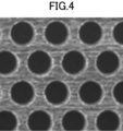
- FIG. 4 is an enlarged view showing an example of a fine hole provided on a surface of a cover body in the sensor cover according to the embodiment of the present invention. It is a figure which shows the effect
- FIG. 4 is an enlarged view showing an example of a fine hole provided on a surface of a cover body in the sensor cover according to the embodiment of the present invention. It is a figure which shows the effect
- FIG. 5 is a diagram illustrating an example of a comparative example in which the amino acid concentration is measured without using the sensor cover according to the embodiment of the present invention.
- FIG. 7 is a diagram showing an example of a case where the amino acid concentration is measured using a conventional sensor cover as a comparative example. It is a figure showing the example of measurement of the amino acid concentration by the sensor device using the cover for sensors by an embodiment of the present invention.
- FIG. 9 is a diagram illustrating an example in which an amino acid concentration in a culture solution different from those in FIGS. 6 to 8 is measured using the sensor cover according to the embodiment of the present invention.
- FIG. 9 is a diagram illustrating an example in which an amino acid concentration in a culture solution different from those in FIGS. 6 to 8 is measured using the sensor cover according to the embodiment of the present invention.
- FIG. 1 is a cross-sectional view showing an example in which a sensor device provided with a sensor cover according to an embodiment of the present invention is applied to a culture tank for amino acids.
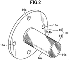
- FIG. 2 is a perspective view showing the appearance of the sensor cover according to the embodiment of the present invention.
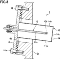
- FIG. 3 is an enlarged sectional view showing a state in which the sensor device according to the embodiment of the present invention is attached to a side wall surface of a culture tank.
- a sensor device 1 having a sensor cover is provided on a side wall surface 2 a of a culture tank 2, which is a container containing a liquid, and is stored in the culture tank 2. It is configured to measure the concentration of amino acids in the culture solution L in-line. Further, a sensor is disposed inside the sensor device 1, and a signal acquired by the sensor is transmitted to the measuring device main body 4. Further, in the present embodiment, the culture tank 2 has a substantially cylindrical shape, and is provided with a stirrer 6 for stirring the culture solution along the central axis thereof. The stirrer 6 is provided with a plurality of blades 6a for stirring the culture solution L.
- the culture solution L in the culture tank 2 is stirred to be homogeneous.
- oxygen or air is introduced into the culture tank 2 from a supply device (not shown). Therefore, the culture solution L contains microbubbles of supplied oxygen and air and microbubbles of carbon dioxide gas generated by the microorganism being cultured.
- the sensor device 1 includes a sensor cover 10 according to the embodiment of the present invention, and a sensor 12 disposed inside the sensor cover 10.
- the sensor cover 10 includes a substantially cylindrical cover body 14 and a flange portion 16 provided at a base end of the cover body 14 and fixed to the side wall surface 2 a of the culture tank 2.
- the cover body 14 is formed of a stainless steel thin plate, has a substantially cylindrical shape with a closed end, and is arranged so as to surround the sensor 12. Further, as will be described later, the cover main body 14 is provided with a large number of fine holes on the entire surface, and the liquid in the culture tank 2 can flow into the cover main body 14 through these fine holes.
- the cover body can be formed in any shape other than a cylindrical shape such as a rectangular parallelepiped. Further, the cover body can be formed of a metal other than stainless steel or a resin such as polytetrafluoroethylene, and is preferably formed of a material that is not easily damaged by the flow of the liquid caused by stirring.
- the flange portion 16 is a stainless steel disk, and the cover body 14 is fixed to the center by welding and integrated. Further, the cover body 14 is attached perpendicular to the plate surface of the flange portion 16.
- the flange portion 16 is provided with a bolt hole 16a, and the flange portion 16 is fixed to the outside of the side wall surface 2a by a fixing bolt 18a.
- a packing 18b is arranged between the flange portion 16 and the side wall surface 2a to ensure watertightness between the flange portion 16 and the side wall surface 2a. Further, as shown in FIG. 3, the portion for fixing the flange portion 16 outside the side wall surface 2a is formed so as to be inclined with respect to the vertical.
- the cover body 14 projects obliquely downward from the side wall surface of the container toward the inside.
- the mounting angle of the cover main body 14 can be set to an angle that suppresses the inflow of bubbles into the cover main body 14 and suppresses the accumulation of liquid near the cover main body 14 and the propagation of various bacteria.
- the angle can be set close to horizontal depending on the properties of the liquid.
- the center axis of the cover body 14 is inclined by about 16 degrees with respect to the horizontal axis.
- a transmission / reflection type near-infrared spectroscopic sensor (NIR sensor) is employed as the sensor 12, and the concentration of the amino acid in the culture solution L is measured by near-infrared analysis.
- NIR sensor near-infrared spectroscopic sensor
- the sensor cover 10 of the present embodiment is not limited to an NIR sensor, but may be a spectroscopic sensor using ultraviolet light or visible light, another optical sensor, an electromagnetic sensor for measuring dielectric constant or conductivity, or the like. And a sensor device can be configured in combination with these sensors.
- the sensor 12 includes a rod-shaped sensor probe 12a having a circular cross section, and a measuring unit 12b is provided at the tip thereof.
- the sensor probe 12a extends inside the cover main body 14 through an opening provided at the center of the flange portion 16 of the sensor cover 10.
- the sensor probe 12a extends along the center axis of the cover main body 14, and the measuring section 12b provided at the front end thereof is located near the front end of the cover main body 14.
- the outer diameter of the sensor probe 12a is about 20 mm, and the surrounding area is surrounded by a cover body 14 having an outer diameter of about 60 mm.
- FIG. 4 is an enlarged view showing an example of the fine holes provided on the surface of the cover main body 14.
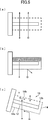
- FIG. 5 is a diagram schematically showing a comparison between the operation of the conventional sensor cover and the operation of the sensor cover of the present embodiment.
- the cover body 14 of the sensor cover 10 has a large number of fine holes formed on the entire surface thereof, so that the surrounding liquid can flow into the inside of the cover body 14. ing.
- the size of each fine hole provided on the lower surface of the cover main body 14 is different from the size of each fine hole provided on the upper surface.
- the lower surface of the cover body 14 is provided with a lower transmission part 14a through which liquid passes
- the upper surface is provided with an upper transmission part 14b through which liquid passes, and is provided in the lower transmission part 14a.
- the formed fine holes are formed smaller than the fine holes provided in the upper transmission portion 14b.
- the lower transmission part 14 a is formed on the entire lower semicircle part corresponding to the lower semicircle of the cover body 14 having a circular cross section
- the upper transmission part 14 b is formed on the cover body 14. It is formed on the entire upper semicircle portion corresponding to the upper semicircle. Also, a large number of the same fine holes as the lower transmission portion 14a are formed on the entire front surface 14c of the cover body 14.
- the "lower surface” of the cover main body 14 means the surface on which the light shines when the light is projected from below vertically onto the sensor cover 10 installed in use.
- the “surface” means a surface to which light shines when light is projected from vertically above.
- a large number of fine holes are formed on the entire “lower surface” and “upper surface” of the cover main body 14, but the fine holes are not necessarily formed on the entire surface. What is necessary is just to be formed in a part.
- the fine holes are also provided on the distal end surface 14c of the cover main body 14, the fine holes need not be provided on the distal end surface 14c.
- the lower transmission portion 14a and the upper transmission portion 14b are arranged with substantially circular fine holes in a staggered manner. That is, the respective fine holes are arranged such that a line connecting the centers of three adjacent fine holes forms an equilateral triangle.
- the lower transmission portion 14a and the upper transmission portion 14b are formed by etching a thin stainless steel plate to form a large number of fine holes.
- a circular hole having a diameter D of about 180 ⁇ m is arranged at a pitch P of about 320 ⁇ m (the length of a side of an equilateral triangle connecting the center of the circle) so that the lower transmitting portion is formed. 14a are formed.
- the upper transmission portion 14b is formed by arranging circular holes having a diameter D of about 850 ⁇ m at a pitch P of about 1270 ⁇ m, or forming circular holes having a diameter D of about 350 ⁇ m at a pitch P of about 630 ⁇ m. It consists of an array.
- the lower transmission portion 14a in which circular holes having a diameter D of about 180 ⁇ m are arranged at a pitch P of about 320 ⁇ m has an aperture ratio of about 28.7%, and has a mesh of approximately 80 ° (80 mesh: 1 inch). (A net formed by arranging 80 element wires vertically and horizontally between them). Further, the upper transmission portion 14b in which circular holes having a diameter D of about 850 ⁇ m are arranged at a pitch P of about 1270 ⁇ m has an aperture ratio of about 40.6%, which corresponds to a net of about 20 °.
- the upper transmission portion 14b in which circular holes having a diameter D of about 350 ⁇ m are arranged at a pitch P of about 630 ⁇ m has an aperture ratio of about 28%, which is equivalent to a net of about 40 °.
- the aperture ratio becomes about 20.5%, which corresponds to a net of approximately 150 °, and a circle having a diameter D of about 150 ⁇ m.
- the aperture ratio is about 32.5%, which is equivalent to a net of about 100 °.
- the lower transmission portion 14a and the upper transmission portion 14b are formed by forming a large number of fine holes in a thin plate, but are formed by weaving, knitting, or the like a thin element wire.
- the lower transmission part 14a and the upper transmission part 14b can also be constituted by a mesh.
- the "micropore” is formed as a space between the wires constituting the mesh, and the "diameter of the micropore” means the distance between adjacent wires.
- the diameter of the fine holes provided in the lower transmission part 14a is set to be about 100 ⁇ m to about 400 ⁇ m. More preferably, the diameter of the fine holes provided in the lower transmission part 14a is set to be about 150 ⁇ m to about 400 ⁇ m.
- the fine holes provided in the upper transmission portion 14b be formed to be larger than the diameter of the fine holes in the lower transmission portion.
- the diameter of the fine holes of the upper transmission part 14b is preferably set to a diameter that can sufficiently suppress the flow of bubbles through the upper transmission part 14b due to the downward flow of the liquid.
- the diameter of the fine holes provided in the upper transmission part 14b is set to about 1.5 to about 5 times the diameter of the fine holes provided in the lower transmission part 14a.
- the cover main body 14 since the lower transmission portion 14a of the cover main body 14 has a small hole with a small diameter, it rises from below. Large air bubbles are prevented from entering the cover body 14.
- the cover main body 14 since the cover main body 14 is provided so as to protrude obliquely downward from the side wall surface 2a of the culture tank 2, the air bubbles prevented from entering by the cover main body 14 are covered by the cover main body 14. It is easy to move diagonally upward along the lower surface of the main body 14, and many air bubbles move upward while easily bypassing the sensor cover 10.
- the ratio of the bubbles approaching the sensor cover 10 from below is low. In many cases, these intrusions are largely suppressed by the lower transmission portion 14a. Further, the upper transmission part 14b also prevents the intrusion of some bubbles approaching the sensor cover 10 from the side or the like.
- the cover main body 14 is provided so as to protrude obliquely downward, air bubbles that have entered the cover main body 14 move upward toward the base end of the cover main body 14.
- the measuring portion 12b of the sensor probe 12a disposed in the cover main body 14 is disposed near the tip of the cover main body 14, the air bubbles in the cover main body 14 move away from the measuring portion 12b of the sensor 12. Moved to For this reason, the influence of the bubbles that have entered the cover body 14 on the measurement is further reduced.
- the influence of bubbles on measurement is effectively reduced.
- FIG. 6 is a diagram illustrating an example of the case where the amino acid concentration is measured without using the sensor cover 10
- FIG. 7 is a diagram illustrating the case where the amino acid concentration is measured using the conventional sensor cover (strainer). It is a figure showing an example.
- FIG. 8 is a diagram showing an example of measuring the amino acid concentration by the sensor device 1 using the sensor cover 10 according to the embodiment of the present invention.
- 9 and 10 are diagrams showing examples in which the amino acid concentration in a culture solution different from those in FIGS. 6 to 8 is measured using two types of sensor covers according to the embodiment of the present invention. .
- the senor 12 is an NIR sensor, and light received by the sensor probe 12a is guided to the measuring instrument main body 4 (FIG. 1) via an optical fiber.
- the measuring device main body 4 an NIR spectrum of the guided light is acquired.
- the concentration of amino acids contained in the culture solution L can be estimated.
- 6 to 8 are graphs showing the time-dependent changes in the amino acid concentration estimated in this manner.
- FIG. 6 is an example in which the amino acid concentration in the culture solution L in the culture tank 2 is measured (estimated) using the sensor 12 without attaching the sensor cover 10.
- the estimated value fluctuates greatly every measurement. This is considered that bubbles mixed in the culture solution L affect the light received by the sensor probe 12a, and the estimated value varies.
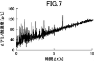
- FIG. 7 shows an example in which the amino acid concentration of the culture solution L measured in the example shown in FIG. 6 is measured using the sensor 12 covered with a strainer (conventional sensor cover) of 20 °.
- a strainer conventional sensor cover
- FIG. 8 shows an example of the case where the amino acid concentration of the culture solution L measured in the examples shown in FIGS. 6 and 7 is measured using the sensor cover 10 according to the embodiment of the present invention.
- a mesh in which circular holes of about 180 ⁇ m are arranged at a pitch of about 320 ⁇ m is provided as the lower transmission section 14a, and circular holes of about 850 ⁇ m are arranged at a pitch of about 1270 ⁇ m as the upper transmission section 14b.
- the cover body 14 provided with the mesh is used.
- the variation in the estimated value of the amino acid concentration is extremely small as compared with the examples shown in FIGS. 6 and 7. A sufficiently reliable estimate has been obtained.
- FIGS. 9 and 10 an example of estimating the amino acid concentration in the culture tank 2 in which amino acids different from those in FIGS. 6 to 8 are cultured will be described.
- aeration culture is performed in the culture tank 2 in which an example of estimating the amino acid concentration is shown in FIGS. 6 to 8, and fine bubbles having a diameter of about 150 ⁇ m are generated by a supply device (not shown).
- L a supply device
- no air bubbles were introduced in the culture tank 2 shown in the measurement examples in FIGS. 9 and 10, and the mixed air bubbles had a diameter of about 350 ⁇ m due to carbon dioxide gas generated in the culture solution L. Fine bubbles are the center.
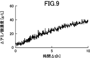
- FIG. 9 shows an example of the case where the amino acid concentration of the culture solution L is measured using the sensor cover 10 according to the embodiment of the present invention.
- a mesh in which circular holes of about 180 ⁇ m are arranged at a pitch of about 320 ⁇ m is provided as the lower transmitting part 14 a, and a mesh is formed as the upper transmitting part 14 b.
- a cover body 14 provided with a mesh in which 850 ⁇ m circular holes are arranged at a pitch of about 1270 ⁇ m is used.
- FIG. 9 by covering the sensor 12 with the sensor cover 10 of the present embodiment, variation in the estimated value of the amino acid concentration is suppressed to a small value, and a highly reliable estimated value is obtained.
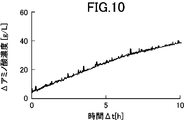
- FIG. 10 shows an example in which the same amino acid concentration in the culture solution L as in the example shown in FIG. 9 is measured using the sensor cover 10 according to the embodiment of the present invention.
- a mesh in which circular holes of about 180 ⁇ m are arranged at a pitch of about 320 ⁇ m is provided as the lower transmitting section 14a, and circular holes of about 350 ⁇ m are arranged at a pitch of about 630 ⁇ m as the upper transmitting section 14b.
- the cover body 14 provided with the mesh is used.
- the variation in the estimated value of the amino acid concentration is extremely small, and a sufficiently reliable estimated value is obtained.
- the variation in the estimated value is further smaller than in the example shown in FIG.
- the size of the micropores provided in the lower transmission part 14a and the upper transmission part 14b is appropriately set according to the properties of the bubbles mixed in the liquid to be measured and the properties of the liquid such as viscosity. As a result, the effect of the inclusion of bubbles can be sufficiently suppressed.
- the cover main body 14 arranged so as to surround the sensor 12 is provided with the lower transmission part 14a and the upper transmission part 14b through which the liquid passes (FIG. 2). Therefore, the liquid to be measured can flow into and out of the cover body 14 constantly. As a result, the liquid in the cover main body 14 is constantly replaced, and the sensor 12 disposed in the cover main body 14 can continuously measure the characteristics of the liquid in real time (FIGS. 8 to 10). Further, since the fine holes provided in the lower transmitting portion 14a are formed smaller than the fine holes provided in the upper transmitting portion 14b (FIG. 5C), they have risen from below the cover main body 14.
- Bubbles are less likely to pass through the fine holes of the lower transmission portion 14a, and the intrusion of bubbles into the cover main body 14 can be effectively suppressed.
- the fine holes of the upper transmitting portion 14b are formed larger than the fine holes of the lower transmitting portion 14a, the air bubbles that have entered the cover main body 14 rise in the cover main body and are discharged through the upper transmitting portion 14b. Easy to be. As a result, it is possible to suppress the air bubbles that have entered the cover main body 14 from remaining in the cover main body 14 and adversely affect the measurement value of the sensor 12.
- the cover body 14 is formed in a substantially cylindrical shape (FIG. 2), air bubbles that float from the lower side of the cover body 14 are formed on the lower side of the cover body 14. It is easy to flow upward along the surface, and the intrusion of bubbles into the cover main body 14 can be further suppressed. Further, since the cover main body 14 is formed in a substantially cylindrical shape, air bubbles that have entered the cover main body 14 and floated are collected at the highest portion in the cover main body 14 and are less likely to contact the sensor 12. Accordingly, even when air bubbles enter the cover main body 14, adverse effects on the measurement can be suppressed to a minimum.
- the lower transmitting portion 14a and the upper transmitting portion 14b are provided on the entire surface of the lower semicircular portion and the upper semicircular portion, respectively (FIG. 2),
- the portion of the cover body 14 through which the liquid permeates can be made extremely large.
- the liquid in the cover body 14 is easily replaced with an external liquid, and the characteristics of the liquid can be accurately measured in real time.
- the fine holes of the lower transmission portion 14a and the upper transmission portion 14b are formed by the holes provided in the thin metal plate (FIG. 4).
- the liquid is less likely to adhere to the lower transmission part 14a and the upper transmission part 14b as compared with the case where the lower transmission part and the upper transmission part are formed by a net formed by knitting, thereby improving the maintainability of the sensor cover 10. Can be.
- the cover body 14 projects obliquely downward from the side wall surface 2a of the culture tank 2 which is a container containing the liquid (FIG. 3), so that it rises from below.
- the air bubbles that have reached the cover main body 14 can easily flow upward along the lower surface of the cover main body 14, and can effectively prevent entry into the cover main body 14.
- air bubbles that have entered the cover main body 14 collect at the base end of the cover main body 14 located above, and thus move away from the measurement unit 12b of the sensor 12 disposed near the distal end of the cover main body 14, and adversely affect the measurement. Can be reduced.
- the amino acid concentration in the culture solution in which bubbles are mixed is estimated by spectroscopic analysis. It can be applied to measure properties.
- the present invention is applied to the measurement of the concentration of a specific component in a liquid.
- the sensor of any sensor that measures characteristics of the liquid itself, such as the dielectric constant or conductivity of the liquid is used.
- the present invention can be applied to a cover for use.
- the present invention is applied to the measurement of the amino acid concentration in a culture solution.
- the present invention is applied to the measurement of various component concentrations in a liquid, not limited to the amino acid concentration. This makes it possible to accurately manage the aeration culture, and to increase the accumulation and yield of products in the culture solution.
- the carbon source concentration can be measured in-line.
Landscapes
- Chemical & Material Sciences (AREA)
- Health & Medical Sciences (AREA)
- Life Sciences & Earth Sciences (AREA)
- Engineering & Computer Science (AREA)
- Bioinformatics & Cheminformatics (AREA)
- Organic Chemistry (AREA)
- Wood Science & Technology (AREA)
- Zoology (AREA)
- Biochemistry (AREA)
- General Health & Medical Sciences (AREA)
- Physics & Mathematics (AREA)
- Analytical Chemistry (AREA)
- Biomedical Technology (AREA)
- General Engineering & Computer Science (AREA)
- Sustainable Development (AREA)
- Genetics & Genomics (AREA)
- Microbiology (AREA)
- Biotechnology (AREA)
- Spectroscopy & Molecular Physics (AREA)
- General Physics & Mathematics (AREA)
- Immunology (AREA)
- Pathology (AREA)
- Clinical Laboratory Science (AREA)
- Investigating Or Analysing Materials By Optical Means (AREA)
- Apparatus Associated With Microorganisms And Enzymes (AREA)
- Preparation Of Compounds By Using Micro-Organisms (AREA)
Abstract
L'invention concerne un couvercle de capteur qui est capable de réduire, avec une structure simple, l'influence des bulles d'air mélangées dans un liquide ; et un dispositif de capteur équipé de celui-ci. La présente invention concerne un couvercle (10) d'un capteur qui mesure une propriété d'un liquide dans lequel des bulles d'air sont mélangées, caractérisé en ce qu'il comprend : un corps de couvercle (14) qui est disposé de façon à entourer un capteur (12) ; étant doté, au moins dans une section d'une surface de côté inférieur du corps de couvercle (14), d'une section de passage de côté inférieur (14a) qui permet au liquide de passer à travers celle-ci ; étant doté, au moins dans une section d'une surface de côté supérieur du corps de couvercle (14), d'une section de passage de côté supérieur (14b) qui permet au liquide de passer à travers celle-ci ; ayant de nombreux trous fins pour permettre au liquide de passer à travers ceux-ci formés dans chacune de la section de passage de côté inférieur (14a) et de la section de passage de côté supérieur (14b) ; et ayant les trous fins ménagés dans la section de passage de côté inférieur (14a) qui sont formés en des dimensions plus petites que les trous fins ménagés dans la section de passage de côté supérieur (14b).
Priority Applications (4)
| Application Number | Priority Date | Filing Date | Title |
|---|---|---|---|
| JP2020528836A JP7397410B2 (ja) | 2018-07-06 | 2019-06-28 | センサー用カバー及びそれを備えたセンサー装置、及び液体の特性の測定方法、通気培養における代謝生産物の製造方法 |
| EP19831001.3A EP3819629A4 (fr) | 2018-07-06 | 2019-06-28 | Couvercle de capteur, dispositif de capteur équipé de celui-ci, procédé de mesure de propriété de liquide et procédé de production de métabolite dans une culture d'aération |
| US17/136,132 US20210190677A1 (en) | 2018-07-06 | 2020-12-29 | Sensor cover and sensor apparatus including same, method for measuring properties of a solution, and method for manufacturing metabolic products in an aerobic culture |
| JP2023175958A JP2023184548A (ja) | 2018-07-06 | 2023-10-11 | センサー用カバー及びそれを備えたセンサー装置、及び液体の特性の測定方法、通気培養における代謝生産物の製造方法 |
Applications Claiming Priority (2)
| Application Number | Priority Date | Filing Date | Title |
|---|---|---|---|
| JP2018-128836 | 2018-07-06 | ||
| JP2018128836 | 2018-07-06 |
Related Child Applications (1)
| Application Number | Title | Priority Date | Filing Date |
|---|---|---|---|
| US17/136,132 Continuation US20210190677A1 (en) | 2018-07-06 | 2020-12-29 | Sensor cover and sensor apparatus including same, method for measuring properties of a solution, and method for manufacturing metabolic products in an aerobic culture |
Publications (1)
| Publication Number | Publication Date |
|---|---|
| WO2020009022A1 true WO2020009022A1 (fr) | 2020-01-09 |
Family
ID=69059517
Family Applications (1)
| Application Number | Title | Priority Date | Filing Date |
|---|---|---|---|
| PCT/JP2019/025828 Ceased WO2020009022A1 (fr) | 2018-07-06 | 2019-06-28 | Couvercle de capteur, dispositif de capteur équipé de celui-ci, procédé de mesure de propriété de liquide et procédé de production de métabolite dans une culture d'aération |
Country Status (4)
| Country | Link |
|---|---|
| US (1) | US20210190677A1 (fr) |
| EP (1) | EP3819629A4 (fr) |
| JP (2) | JP7397410B2 (fr) |
| WO (1) | WO2020009022A1 (fr) |
Cited By (2)
| Publication number | Priority date | Publication date | Assignee | Title |
|---|---|---|---|---|
| JP2024541399A (ja) * | 2022-08-16 | 2024-11-08 | エルジー・ケム・リミテッド | 溶液の状態測定装置 |
| KR20240173512A (ko) * | 2023-06-05 | 2024-12-12 | 주식회사 큐빅케이 | 분광기용 기포차단장치 및 이를 포함하는 생물반응기 |
Families Citing this family (1)
| Publication number | Priority date | Publication date | Assignee | Title |
|---|---|---|---|---|
| KR20240112611A (ko) * | 2023-01-12 | 2024-07-19 | 주식회사 큐빅케이 | 광학분석기 및 이를 포함하는 생물반응기 |
Citations (5)
| Publication number | Priority date | Publication date | Assignee | Title |
|---|---|---|---|---|
| JPS551574A (en) * | 1978-06-20 | 1980-01-08 | Matsushita Electric Ind Co Ltd | Fine particle detector |
| JPS62192242U (fr) * | 1986-05-27 | 1987-12-07 | ||
| JPH04212044A (ja) * | 1991-01-28 | 1992-08-03 | Komatsugawa Kakoki Kk | 濁度計 |
| JP3074781B2 (ja) | 1991-03-12 | 2000-08-07 | 味の素株式会社 | 発酵法によるl−リジンの製造法 |
| JP2003075344A (ja) * | 2001-08-30 | 2003-03-12 | Ajinomoto Co Inc | 濁度センサ |
Family Cites Families (10)
| Publication number | Priority date | Publication date | Assignee | Title |
|---|---|---|---|---|
| JPS62114353U (fr) * | 1986-01-08 | 1987-07-21 | ||
| JP3049297B2 (ja) * | 1990-11-08 | 2000-06-05 | 東京理化器械株式会社 | 菌体量の計測方法 |
| JPH11248696A (ja) * | 1998-02-28 | 1999-09-17 | Horiba Ltd | 水質測定装置 |
| JP2000002685A (ja) * | 1998-05-11 | 2000-01-07 | Heraeus Electro Nite Internatl Nv | ガスセンサ用ハウジング |
| JP2000097930A (ja) * | 1998-09-21 | 2000-04-07 | Horiba Ltd | 水質測定装置 |
| DE19942740A1 (de) * | 1999-09-07 | 2001-03-22 | Heraeus Electro Nite Int | Gehäuse für einen Sensor |
| JP5072777B2 (ja) * | 2008-09-02 | 2012-11-14 | 株式会社堀場製作所 | 試料測定装置 |
| US9354158B1 (en) * | 2012-01-20 | 2016-05-31 | Tasseron Sensors, Inc. | Duct averaging sensor having a connector |
| KR101248567B1 (ko) * | 2012-04-25 | 2013-04-12 | 주식회사 인바이온 | 수족관내 녹조발생 억제 및 병원균 사멸 장치 |
| WO2017037899A1 (fr) * | 2015-09-02 | 2017-03-09 | 富士電機株式会社 | Dispositif d'analyse et dispositif de traitement de gaz d'échappement |
-
2019
- 2019-06-28 WO PCT/JP2019/025828 patent/WO2020009022A1/fr not_active Ceased
- 2019-06-28 EP EP19831001.3A patent/EP3819629A4/fr not_active Withdrawn
- 2019-06-28 JP JP2020528836A patent/JP7397410B2/ja active Active
-
2020
- 2020-12-29 US US17/136,132 patent/US20210190677A1/en active Pending
-
2023
- 2023-10-11 JP JP2023175958A patent/JP2023184548A/ja active Pending
Patent Citations (6)
| Publication number | Priority date | Publication date | Assignee | Title |
|---|---|---|---|---|
| JPS551574A (en) * | 1978-06-20 | 1980-01-08 | Matsushita Electric Ind Co Ltd | Fine particle detector |
| JPS62192242U (fr) * | 1986-05-27 | 1987-12-07 | ||
| JPH04212044A (ja) * | 1991-01-28 | 1992-08-03 | Komatsugawa Kakoki Kk | 濁度計 |
| JP3074781B2 (ja) | 1991-03-12 | 2000-08-07 | 味の素株式会社 | 発酵法によるl−リジンの製造法 |
| JP2003075344A (ja) * | 2001-08-30 | 2003-03-12 | Ajinomoto Co Inc | 濁度センサ |
| JP4420168B2 (ja) | 2001-08-30 | 2010-02-24 | 味の素株式会社 | 濁度センサ |
Non-Patent Citations (1)
| Title |
|---|
| See also references of EP3819629A4 |
Cited By (4)
| Publication number | Priority date | Publication date | Assignee | Title |
|---|---|---|---|---|
| JP2024541399A (ja) * | 2022-08-16 | 2024-11-08 | エルジー・ケム・リミテッド | 溶液の状態測定装置 |
| JP7733241B2 (ja) | 2022-08-16 | 2025-09-02 | エルジー・ケム・リミテッド | 溶液の状態測定装置 |
| KR20240173512A (ko) * | 2023-06-05 | 2024-12-12 | 주식회사 큐빅케이 | 분광기용 기포차단장치 및 이를 포함하는 생물반응기 |
| KR102834978B1 (ko) | 2023-06-05 | 2025-07-17 | 주식회사 큐빅케이 | 분광기용 기포차단장치 및 이를 포함하는 생물반응기 |
Also Published As
| Publication number | Publication date |
|---|---|
| JP7397410B2 (ja) | 2023-12-13 |
| EP3819629A4 (fr) | 2022-04-13 |
| JPWO2020009022A1 (ja) | 2021-08-02 |
| US20210190677A1 (en) | 2021-06-24 |
| JP2023184548A (ja) | 2023-12-28 |
| EP3819629A1 (fr) | 2021-05-12 |
Similar Documents
| Publication | Publication Date | Title |
|---|---|---|
| JP2023184548A (ja) | センサー用カバー及びそれを備えたセンサー装置、及び液体の特性の測定方法、通気培養における代謝生産物の製造方法 | |
| CN105143857B (zh) | 具有多个检测通道的荧光计 | |
| WO1996012183A1 (fr) | Procede de determination de la teneur organique d'effluents provenant de fabriques de pate et de papier | |
| JP2008261770A (ja) | 光学式試料測定装置、光学セル、及び、水質測定装置 | |
| CN113603242B (zh) | 一种基于das技术对曝气中区域曝气效果监测的方法 | |
| US20180052145A1 (en) | Wastewater Analyser Assembly | |
| US10190980B2 (en) | System and method for simultaneous measurement of turbidity, color and chlorine content of a sample of a liquid | |
| US20260125724A1 (en) | Method for manufacturing fermentation products with a sensor device | |
| JP2010078598A (ja) | 水中のホウ素を検出する電気化学的方法 | |
| US7662342B2 (en) | Measuring cell | |
| KR102083327B1 (ko) | 측정 정밀도를 높이기 위한 검사용 유로 구조 | |
| KR101466384B1 (ko) | 탁도센서 | |
| JPH053971Y2 (fr) | ||
| US10132749B1 (en) | System and method for simultaneous measurement of turbidity and chlorine content of a sample of a liquid | |
| CN105699613A (zh) | 水质监测系统 | |
| US20170050226A1 (en) | Self-cleaning monitoring system for biomass processing | |
| JP7733241B2 (ja) | 溶液の状態測定装置 | |
| CN201156034Y (zh) | 水质量测仪 | |
| JP2009527244A (ja) | 培養を観測するための装置および方法 | |
| CN221594423U (zh) | 多参数水质检测仪 | |
| JP2008064661A (ja) | 酸素測定装置および酸素測定方法 | |
| Sudirman et al. | Development of an IoT-Based Sensor for Indirect Measurement of Underwater CO 2 Levels in Aquascape Environments | |
| EP1630543A1 (fr) | Détecteur pour la détermination spectroscopique des composants résolus dans un milieu liquide | |
| CN212718792U (zh) | 一种浸没式在线分析仪表传感器安装装置 | |
| CN207263616U (zh) | 一种用于光纤检测的玻璃反射式探头 |
Legal Events
| Date | Code | Title | Description |
|---|---|---|---|
| 121 | Ep: the epo has been informed by wipo that ep was designated in this application |
Ref document number: 19831001 Country of ref document: EP Kind code of ref document: A1 |
|
| ENP | Entry into the national phase |
Ref document number: 2020528836 Country of ref document: JP Kind code of ref document: A |
|
| NENP | Non-entry into the national phase |
Ref country code: DE |
|
| WWW | Wipo information: withdrawn in national office |
Ref document number: 2019831001 Country of ref document: EP |