WO2020009031A1 - Centrale de production d'énergie utilisant un corps de flottabilité et son procédé de production d'énergie - Google Patents
Centrale de production d'énergie utilisant un corps de flottabilité et son procédé de production d'énergie Download PDFInfo
- Publication number
- WO2020009031A1 WO2020009031A1 PCT/JP2019/025863 JP2019025863W WO2020009031A1 WO 2020009031 A1 WO2020009031 A1 WO 2020009031A1 JP 2019025863 W JP2019025863 W JP 2019025863W WO 2020009031 A1 WO2020009031 A1 WO 2020009031A1
- Authority
- WO
- WIPO (PCT)
- Prior art keywords
- tank
- water
- variable capacity
- buoyant body
- air
- Prior art date
- Legal status (The legal status is an assumption and is not a legal conclusion. Google has not performed a legal analysis and makes no representation as to the accuracy of the status listed.)
- Ceased
Links
Images







Classifications
-
- F—MECHANICAL ENGINEERING; LIGHTING; HEATING; WEAPONS; BLASTING
- F03—MACHINES OR ENGINES FOR LIQUIDS; WIND, SPRING, OR WEIGHT MOTORS; PRODUCING MECHANICAL POWER OR A REACTIVE PROPULSIVE THRUST, NOT OTHERWISE PROVIDED FOR
- F03B—MACHINES OR ENGINES FOR LIQUIDS
- F03B13/00—Adaptations of machines or engines for special use; Combinations of machines or engines with driving or driven apparatus; Power stations or aggregates
- F03B13/06—Stations or aggregates of water-storage type, e.g. comprising a turbine and a pump
-
- F—MECHANICAL ENGINEERING; LIGHTING; HEATING; WEAPONS; BLASTING
- F03—MACHINES OR ENGINES FOR LIQUIDS; WIND, SPRING, OR WEIGHT MOTORS; PRODUCING MECHANICAL POWER OR A REACTIVE PROPULSIVE THRUST, NOT OTHERWISE PROVIDED FOR
- F03B—MACHINES OR ENGINES FOR LIQUIDS
- F03B17/00—Other machines or engines
- F03B17/02—Other machines or engines using hydrostatic thrust
- F03B17/025—Other machines or engines using hydrostatic thrust and reciprocating motion
-
- F—MECHANICAL ENGINEERING; LIGHTING; HEATING; WEAPONS; BLASTING
- F05—INDEXING SCHEMES RELATING TO ENGINES OR PUMPS IN VARIOUS SUBCLASSES OF CLASSES F01-F04
- F05B—INDEXING SCHEME RELATING TO WIND, SPRING, WEIGHT, INERTIA OR LIKE MOTORS, TO MACHINES OR ENGINES FOR LIQUIDS COVERED BY SUBCLASSES F03B, F03D AND F03G
- F05B2220/00—Application
- F05B2220/70—Application in combination with
- F05B2220/706—Application in combination with an electrical generator
-
- F—MECHANICAL ENGINEERING; LIGHTING; HEATING; WEAPONS; BLASTING
- F05—INDEXING SCHEMES RELATING TO ENGINES OR PUMPS IN VARIOUS SUBCLASSES OF CLASSES F01-F04
- F05B—INDEXING SCHEME RELATING TO WIND, SPRING, WEIGHT, INERTIA OR LIKE MOTORS, TO MACHINES OR ENGINES FOR LIQUIDS COVERED BY SUBCLASSES F03B, F03D AND F03G
- F05B2260/00—Function
- F05B2260/40—Transmission of power
-
- F—MECHANICAL ENGINEERING; LIGHTING; HEATING; WEAPONS; BLASTING
- F05—INDEXING SCHEMES RELATING TO ENGINES OR PUMPS IN VARIOUS SUBCLASSES OF CLASSES F01-F04
- F05B—INDEXING SCHEME RELATING TO WIND, SPRING, WEIGHT, INERTIA OR LIKE MOTORS, TO MACHINES OR ENGINES FOR LIQUIDS COVERED BY SUBCLASSES F03B, F03D AND F03G
- F05B2260/00—Function
- F05B2260/40—Transmission of power
- F05B2260/403—Transmission of power through the shape of the drive components
- F05B2260/4031—Transmission of power through the shape of the drive components as in toothed gearing
-
- F—MECHANICAL ENGINEERING; LIGHTING; HEATING; WEAPONS; BLASTING
- F05—INDEXING SCHEMES RELATING TO ENGINES OR PUMPS IN VARIOUS SUBCLASSES OF CLASSES F01-F04
- F05B—INDEXING SCHEME RELATING TO WIND, SPRING, WEIGHT, INERTIA OR LIKE MOTORS, TO MACHINES OR ENGINES FOR LIQUIDS COVERED BY SUBCLASSES F03B, F03D AND F03G
- F05B2260/00—Function
- F05B2260/42—Storage of energy
- F05B2260/422—Storage of energy in the form of potential energy, e.g. pressurized or pumped fluid
-
- F—MECHANICAL ENGINEERING; LIGHTING; HEATING; WEAPONS; BLASTING
- F05—INDEXING SCHEMES RELATING TO ENGINES OR PUMPS IN VARIOUS SUBCLASSES OF CLASSES F01-F04
- F05B—INDEXING SCHEME RELATING TO WIND, SPRING, WEIGHT, INERTIA OR LIKE MOTORS, TO MACHINES OR ENGINES FOR LIQUIDS COVERED BY SUBCLASSES F03B, F03D AND F03G
- F05B2270/00—Control
- F05B2270/10—Purpose of the control system
- F05B2270/20—Purpose of the control system to optimise the performance of a machine
-
- Y—GENERAL TAGGING OF NEW TECHNOLOGICAL DEVELOPMENTS; GENERAL TAGGING OF CROSS-SECTIONAL TECHNOLOGIES SPANNING OVER SEVERAL SECTIONS OF THE IPC; TECHNICAL SUBJECTS COVERED BY FORMER USPC CROSS-REFERENCE ART COLLECTIONS [XRACs] AND DIGESTS
- Y02—TECHNOLOGIES OR APPLICATIONS FOR MITIGATION OR ADAPTATION AGAINST CLIMATE CHANGE
- Y02E—REDUCTION OF GREENHOUSE GAS [GHG] EMISSIONS, RELATED TO ENERGY GENERATION, TRANSMISSION OR DISTRIBUTION
- Y02E10/00—Energy generation through renewable energy sources
- Y02E10/20—Hydro energy
-
- Y—GENERAL TAGGING OF NEW TECHNOLOGICAL DEVELOPMENTS; GENERAL TAGGING OF CROSS-SECTIONAL TECHNOLOGIES SPANNING OVER SEVERAL SECTIONS OF THE IPC; TECHNICAL SUBJECTS COVERED BY FORMER USPC CROSS-REFERENCE ART COLLECTIONS [XRACs] AND DIGESTS
- Y02—TECHNOLOGIES OR APPLICATIONS FOR MITIGATION OR ADAPTATION AGAINST CLIMATE CHANGE
- Y02E—REDUCTION OF GREENHOUSE GAS [GHG] EMISSIONS, RELATED TO ENERGY GENERATION, TRANSMISSION OR DISTRIBUTION
- Y02E60/00—Enabling technologies; Technologies with a potential or indirect contribution to GHG emissions mitigation
- Y02E60/16—Mechanical energy storage, e.g. flywheels or pressurised fluids
Definitions
- the present invention relates to a power plant that generates power using small hydropower and a method of generating power, and in particular, raises and lowers a buoyant body by repeatedly injecting river water or the like into a water tank and draining water stored in the water tank.
- the present invention also relates to a power plant using a buoyant body that generates power using energy that moves up and down the buoyant body, and a power generation method thereof.
- Hydroelectric power generation has been known as a power generation method using water. If the amount of power generation is “10,000 kW or less”, it is called a small hydroelectric power generation. In the classification of the power generation method of the small hydro power generation, there are a “flow-in type” and a “water channel type”. This is a power generation system that is distinguished from large-scale reservoir-type dams and medium-scale dams with regulating ponds, and uses water, such as river water, without storing it.
- This small hydro power generation is a power generation method that makes effective use of energy that is wasted now, such as general rivers, agricultural water, sabo dams, and water and sewage.
- Small hydropower has been attracting attention as an environmentally friendly one that does not involve large-scale development such as dams.
- This small hydropower can generate power stably all day and night. Its capacity factor is as high as 50 to 90%, and it can generate 5 to 8 times as much power as solar power. In addition, the output fluctuation is small, and the system stability and power quality are not affected. Its installation area is small compared to solar power generation equipment.
- a power generation facility using an agricultural irrigation canal is a "run-of-river" type hydroelectric power generation facility that effectively uses water from an agricultural irrigation canal flowing through a river. Water is taken from waterways, and power is generated using the heads of river terraces created by nature.
- a technique related to hydroelectric power generation for example, as disclosed in Japanese Patent Application Laid-Open No. 2016-98782, “Small hydroelectric power generation system”, a water tank from which water flows in from the outside and a water tank provided at a lower position than the water tank and flow from the water tank.
- An arithmetic unit that transmits a command for variable speed control based on the number to the rotation speed control device has been proposed.
- the inventor of the present invention does not use the water as it is in a place where there is abundant water and uses the water as it is for power generation, but once the abundant water is converted to another energy, the power is efficiently generated. Focused on being available.
- the present invention has been made to solve such a problem. That is, the object of the present invention is to use a buoyant body that can be used for power generation, by once converting abundant water into another energy, in a place where there is no difference in elevation, even in a weak water. An object of the present invention is to provide a power generation plant and a power generation method thereof.
- the power plant according to the present invention is a power plant using a buoyant body that generates power using energy that causes the buoyant body (4) to move up and down, A buoyant body (4) arranged in a water tank (5) so as to rise by injecting water and descend by draining; A variable capacity tank (2) in which the filling capacity of the air to be put into the interior changes, A weight (12) placed on top of the variable capacity tank (2) to exhaust air from the variable capacity tank (2); A generator (6) for generating electricity by rotating a turbine with air exhausted from the variable capacity tank (2), When the buoyant body (4) rises by water injection, the upper part of the variable capacity tank (2) is pulled up by using a motion converting means (15) to take in air therein. The air exhausted from the variable capacity tank (2) by the weight of the weight (12) is used to rotate the turbine of the generator (6) to generate power.
- the variable capacity tank (2) is a folding type tank (3) having a bellows-shaped peripheral wall which expands and contracts in the vertical direction.
- a piston (52) is vertically movably inserted into a vertically arranged cylinder (51), and the piston (52) is raised to intake air.
- a cylinder-piston tank (53) configured to be lowered and exhausted.
- the motion converting means (15) has a rack (16) attached to the buoyant body (4) along the vertical movement direction, and a drive hoisting wheel (18) attached to a pinion (17) meshing with the rack (16).
- a second wire (19) is wound around the drive hoisting wheel (18) to raise a member for changing the filling capacity of the variable capacity tank (2) upward.
- Each exhaust pipe (7a, 7b) connected to each variable capacity tank (2a, 2b) is connected to one generator (6), It is possible to adopt a configuration in which the turbine of the generator (6) is rotated by air exhausted from either of the two variable capacity tanks (2a, 2b).
- the power generation method according to the present invention is a power generation method using a buoyant body that generates power using energy that moves up and down the buoyant body (4), Water is poured into the water tanks (5, 5a, 5b) from the water inlets (21), and the buoyancy body (4) is raised in accordance with the rise of the water level in the water tanks (5, 5a, 5b).
- variable capacity tank (2, 2a, 2b) When the buoyant body (4) is raised, the upper part of the variable capacity tank (2, 2a, 2b) is pulled up using the motion converting means (15) to fill the inside with air, Next, when the inside of the variable capacity tank (2, 2a, 2b) is filled with air, the air in the variable capacity tank (2, 2a, 2b) is evacuated by the gravity of the weight (12), and this air is exhausted. The power generation is performed by rotating the turbine of the generator (6) with the air.
- variable capacity tank (2a, 2b) two sets of devices comprising a variable capacity tank (2a, 2b) and a water tank (5a, 5b) containing a buoyant body (4) for lifting the upper part of the variable capacity tank (2a, 2b) are provided.
- air is sucked into one of the variable capacity tanks (2a)
- the gas is exhausted from one of the variable capacity tanks (2a) and the turbine of the generator (6) is rotated to generate electric power.
- the other variable capacity tank (2b) is suctioned.
- the turbine of the generator (6) is rotated by air exhausted from the other variable capacity tank (2b).
- the exhaust from the tanks (2a, 2b) can be used alternately to continuously generate power.
- the buoyant body (4) placed in the water tank (5) is raised by pouring water, thereby pulling up the upper part of the variable capacity tank (2) to take in air therein, Due to the weight of the weight (12), the air exhausted from the variable capacity tank (2) can be used for the rotation of the turbine of the generator (6) to generate electric power.
- a small hydroelectric power plant which has been limited to a place having a head and a flow rate as in the related art, can easily generate power in any place as long as there is water.
- variable capacity tanks (2a, 2b) and water tanks (5a, 5b) containing buoyancy bodies (4) for lifting the upper portions of the respective variable capacity tanks (2a, 2b) are provided.
- stable power can be supplied.
- Power can be generated by taking water from first-grade rivers and ordinary rivers. Power can be taken from agricultural irrigation canals, and power can be generated using water in any of the water and sewage systems.
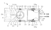
- FIG. 2 is a front view showing a power plant using the buoyant body of the first embodiment.
- FIG. 2 is a plan view illustrating a power plant using the buoyant body of the first embodiment. It is the front view which made a partial cross section which shows the electric power generation method by the electric power generation plant using the buoyant body of Example 1, (a) is the state which pulled up the upper part of a foldable tank and was filled with air, (b) is a foldable type. This is a state in which the air in the tank is exhausted by weights and power is generated by a generator. It is a front view showing an example of a power plant using a buoyancy body of Example 2.
- FIG. 9 is a side view illustrating an example of a power plant using the buoyant body of the second embodiment.
- FIG. 2 It is a schematic explanatory view showing switching of the exhaust of two variable capacity type tanks of Example 2, (a) is a state in which air is taken into one first variable capacity type tank, (b) is one variable capacity type A state in which exhaust (power generation) is performed from the tank and suction is performed in the other variable capacity tank, and FIG. Power generation).
- FIG. 2 is a schematic configuration diagram illustrating a control device that controls water injection and drainage into a water tank and air supply to a generator of the power generation plant of the present invention.
- FIG. 2 is a flowchart which shows the electric power generation method by the electric power generation plant of this invention.
- FIG. 3 It is a front sectional view showing a power plant using a buoyant body of Example 3, (a) is a state where a piston part of a cylinder piston type tank was pulled up and filled with air, and (b) is a cylinder piston type tank. This is a state in which the air inside is exhausted by weights in order to be used for power generation by the generator. It is a front sectional view showing a power plant using a buoyancy body of Example 4, (a) is a state where air is supplied from a variable capacity tank by an air supply tank, and (b) is a state where the variable capacity tank is full. It is.
- the present invention provides a buoyant body that floats on water arranged in a water tank so that it rises by pouring water and descends by draining water, a variable capacity tank in which a filling capacity of air to be introduced changes, and a capacity.
- a weight mounted on the upper part of the variable capacity tank and a generator for generating electricity by rotating a turbine with the air exhausted from the variable capacity tank are provided. It is a power plant.
- FIG. 1 is a front view showing the principle configuration of a power plant using the buoyant body of the first embodiment.
- FIG. 2 is a plan view showing the principle configuration of the power plant using the buoyant body of the first embodiment.
- the power plant 1 using the buoyant body according to the first embodiment shows a principle configuration thereof, and uses a foldable tank 3 having a bellows-shaped wall which expands and contracts vertically as a variable capacity tank 2.
- the power plant 1 using the buoyant body of the first embodiment is a power plant including the foldable tank 3, a water tank 5 containing a buoyant body 4 that floats on water, and a generator 6 that generates power by blast air.
- the foldable tank 3 (variable capacity tank 2) of the first embodiment is a tank capable of storing a large amount of air by increasing the capacity when the inside is filled with air.
- the folding type tank 3 having a bellows-shaped wall which expands and contracts in the up-down direction can take in air into the inside by pulling up the upper part.
- the exhaust pipe at the lower part A check valve 8 is mounted on the upper part so that air can be exhausted from 7.
- the exhaust pipe 7 is connected to a turbine of the generator 6.
- the folding tank 3 is used by expanding and contracting in the vertical direction.
- the foldable tank 3 is sandwiched between support frames 9 so that the upright state is maintained.
- the support frame 9 has a two-piece configuration, but this number is not limited to the two-piece configuration. It is possible to have a three or four configuration. Further, the configuration of the support frame 9 in the illustrated example is not limited as long as the folding type tank 3 can maintain the state of expansion and contraction in the vertical direction and can prevent overturning.
- a horizontal frame 9a is bridged over the support frame 9 having two components, and the first hoisting wheel 10 is suspended from the horizontal frame 9a.
- One end of a first wire 11 is hooked on the first hoisting wheel 10, and the other end of the first wire 11 is hooked on an upper portion (weight 12) of the foldable tank 3.
- the upper part (weight 12) of the foldable tank 3 is pulled up.
- the rotating shaft 13 of the first hoisting wheel 10 is arranged in the longitudinal direction of the horizontal frame 9a, and the second hoisting wheel 14 is attached to each end.
- the rotating shaft 13 of the first hoisting wheel 10 is arranged in the longitudinal direction of the horizontal frame 9a, and the second hoisting wheel 14 is attached to each end.
- an example is shown in which two second hoisting wheels 14 are provided, but this may be one.
- the terms “first” and “second” are not used to indicate grades and orders, but are used for the sake of convenience in classifying members having the same shape and the same function.
- the weight 12 placed on the upper part of the foldable tank 3 is made of metal, cement or the like.
- the weight 12 is used when exhausting the air in the foldable tank 3. However, it is necessary that the weight be such that it can be lifted up and down by the buoyancy of the buoyant body 4 described later.
- the water tank 5 of the power plant 1 using the buoyant body of the first embodiment is filled with water from a general river, agricultural water, a sabo dam, water and sewage, and the like.
- the purpose is to make effective use of the energy that is wasted now in these general rivers, agricultural water, sabo dams, water and sewage systems, and the like.
- the buoyancy member 4 to be put in the water tank 5 may be one filled with air or a porous plastic body.
- a substantially rectangular parallelepiped buoyant body 4 is vertically movably placed in a rectangular parallelepiped water tank 5 without leaving any gap. This is to prevent the buoyant body 4 which rises by pouring water into the water tank 5 and descends by draining it from tilting. This is for moving the buoyancy body 4 up and down smoothly in the water tank 5.
- the kinetic conversion means 15 is a mechanism for temporarily converting the vertical movement of the buoyant body 4 in the water tank 5 into kinetic energy.
- the motion converting means 15 in the illustrated example includes a rack 16 attached to the buoyant body 4 along the vertical movement direction, a drive hoisting wheel 18 attached to a pinion 17 meshing with the rack 16, and the folding type tank 3 attached to the drive hoisting wheel 18. Is wound around a second wire 19 for raising the pressure.
- the motion converting means 15 is provided at two places in one buoyant body 4 in order to uniformly transmit the energy of the vertical movement of the buoyant body 4. Further, the motion converting means 15 is not limited to such a combination of the rack 16 and the pinion 17, but may have various configurations using a hydraulic configuration or a gas pressure configuration.
- the first wire 11 is wound up by the second hoisting wheel 14 and the first hoisting wheel 10 using the buoyant body 4 which rises by pouring water into the water tank 5 and descends by draining by the motion converting means 15.
- the upper portion of the foldable tank 3 is pulled up to fill with air.
- the diameter (L1) of the drive hoisting wheel 18 is about three times the diameter (L2) of the second hoisting wheel 14, as shown in FIG. This is to match the vertical movement interval (H1) of the buoyant body 4 with the vertical movement interval (H2) of the foldable tank 3.
- the vertical movement distance (H1) of the buoyant body 4 and the vertical movement distance (H2) of the foldable tank 3 may be configured to interpose a speed change mechanism such as a double-speed gear.
- an electromagnetic clutch 18a is attached to the drive hoisting wheel 18.
- the drive hoisting wheel 18 and the pinion 17 of the motion converting means 15 are connected by an electromagnetic clutch 18a.
- the foldable tank 3 is lowered, that is, when power is generated, the electromagnetic clutch 18a is disconnected, the foldable tank 3 is smoothly lowered, and the exhaust gas is used to rotate the turbine of the generator 6 without any trouble.
- the connection and disconnection between the drive hoisting wheel 18 and the motion converting means 15 are not limited to the electromagnetic clutch 18a, but may be a mechanical clutch.
- variable capacity tanks 2, water tanks 5 and generators 6 are set on a table 20.
- the illustrated arrangement of the variable capacity tank 2, the water tank 5, and the generator 6 is an example, but is not limited to this arrangement. Further, the invention is not limited to one water tank 5 in one variable capacity tank 2. In the case of a small buoyant body 4, a configuration in which a plurality of water tanks 5 are used to move one variable capacity tank 2 up and down by a plurality of buoyant bodies 4 is also possible.
- FIG. 3 is a partially sectional front view showing a power generation method by the power plant using the buoyant body according to the first embodiment.
- FIG. (B) is a state in which the air in the foldable tank is exhausted with a weight and power is generated by a generator.
- water taken from first-class rivers, ordinary rivers, agricultural waterways, water supply and sewerage systems is used to open and close the water inlet 21 of the water tank 5.
- the valve 22 is opened and put into the water tank 5.
- the buoyancy body 4 rises.
- the rack 16 of the buoyant body 4 rotates the pinion 17, and the drive hoisting wheel 18 connected to the rotating shaft 13 of the pinion 17 rotates. At this time, the electromagnetic clutch 18a of the drive hoisting wheel 18 is connected.
- the second wire 19 wound around the driving hoisting wheel 18 is attached to the first hoisting wheel 10 described above.
- One end of a second wire 19 is hooked on the first hoisting wheel 10, and the other end of the second wire 19 is hooked on the upper part of the foldable tank 3.
- the upper part of the foldable tank 3 is pulled up. Air is taken into the foldable tank 3 from the check valve 8.
- the open / close electromagnetic valve 22 of the water inlet 21 of the water tank 5 is closed and the open / close electromagnetic valve 24 of the drain port 23 is opened to drain water.
- the electromagnetic clutch 18a of the drive hoisting wheel 18 is disconnected.
- a check valve 25 is connected to the exhaust pipe 7 to exhaust air from the foldable tank 3 by the weight of the weight 12. This air is injected, and the turbine of the generator 6 can be vigorously rotated to generate power.
- the generated electric power charges the battery 26. Power is transmitted from the transmission line via the battery 26.
- power is supplied from a battery 26 connected to the generator 6 for the operation of the computer control device and the opening / closing solenoid valves 22 and 24 described later.
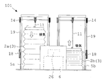
- FIG. 4 is a front view illustrating an example of a power plant using the buoyant body of the second embodiment.
- FIG. 5 is a side view illustrating an example of a power plant using the buoyant body of the second embodiment.
- the power plant 101 according to the second embodiment uses two sets of water tanks 5a and 5b (buoyancy members 4) for one variable capacity tank 2a and 2b having the above-described principle configuration, and generates one set of power. It is desirable to use a configuration in which power is generated by using the machine 6. Each device and equipment has the same configuration as the above-described device.
- the exhaust pipes 7a, 7b connected to the variable capacity tanks 2a, 2b are connected to one generator 6. This is to stably generate power by alternately using two sets of devices.
- FIGS. 6A and 6B are schematic explanatory views showing switching of the exhaust of two variable displacement tanks according to the second embodiment.
- FIG. 6A shows a state where air is taken into one first variable displacement tank
- air is first sucked into one of the first variable displacement tanks 2a.
- the first variable capacity tank 2a (3) is filled with air, the air is exhausted from the first variable capacity tank 2a (3), and the exhaust rotates the turbine of the generator 6.
- FIG. 6A shows a state where air is taken into one first variable displacement tank
- FIG. 6A air is first sucked into one of the first variable displacement tanks 2a.
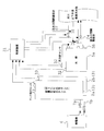
- FIG. 7 is a block diagram showing a control device for controlling water injection and drainage into the water tank and air supply to the generator of the power plant according to the present invention.
- FIG. 8 is a schematic configuration diagram showing a control device for controlling water injection, drainage, and air supply to the generator of the power plant according to the present invention.
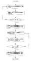
- FIG. 9 is a flowchart showing a power generation method by the power plant of the present invention.
- the control device 31 controls water injection and drainage into the water tanks 5, 5a, 5b of the power generation plant 1, 101 of the present invention. As shown in FIGS.
- a buoyancy sensor 32 a tank operation sensor 33, an amplification processing unit 34 (AMP), and a control signal input unit 35 are connected to the input side of the control device 31.
- the amplification processor 34 (AMP) amplifies the detection signals measured by the buoyancy sensor 32 and the tank operation sensor 33.
- the buoyancy sensor 32 is a sensor that detects that the buoyancy body 4 has risen to the upper ends of the water tanks 5, 5a, 5b. The fact that the buoyant body 4 is at this position means that the buoyant body 4 does not move even if water is injected into the water tanks 5, 5a, 5b.
- the tank operation sensor 33 is a sensor that detects that the variable capacity tanks 2, 2a, 2b have been pulled up to the upper end. This means that air cannot be taken into the variable capacity tanks 2, 2a, 2b even if it is pulled up further.
- the output side of the control device 31 is connected to an on-off valve operation signal output unit 36 for operating each of the on-off solenoid valves 22 and 24 and a display processing unit 37.
- An LED or the like is connected to the display processing unit 37. It informs the current operation state.
- the signal processing unit 38 processes the detection signals of the buoyancy sensor 32 and the tank operation sensor 33 on the input side by an amplification processing unit 34 (AMP) for amplifying the detection signals.
- AMP amplification processing unit 34
- the electromagnetic valve 22 and the opening / closing electromagnetic valve 24 of the drain port 23 are opened and closed. Therefore, the buoyant body 4 placed in the water tanks 5, 5a, 5b is raised by pouring water, and the upper part of the variable capacity tank 2 is pulled up to take in air.
- the variable capacity tanks 2, 2 a, 2 b can generate power by using the air exhausted from the capacity variable tanks 2, 2 a, 2 b by the weight of the weight 12 for the rotation of the turbine of the generator 6.
- the motion converting means 15 is not limited to the configuration of the pinion 17 and the rack 16 described above.
- a sprocket and a chain can be used as the motion converting means.
- a sprocket is arranged at two places in the upper and lower parts of the water tank 5, a chain is hung over both sprockets, and a protrusion of the buoyant body 4 is fixed to one place of the chain.
- a drive hoisting wheel 18 is attached to one upper sprocket, and a second wire 19 is wound around the drive hoisting wheel 18 to pull up a member that varies the filling capacity of the variable capacity tank (foldable tank 3). .
- various structures other than the movement converting means 15 can be used. .
- FIG. 10 is a front sectional view showing a power generation plant using a buoyant body according to the third embodiment.
- (B) is a state in which the air in the cylinder-piston type tank is exhausted by a weight in order to be used for power generation by a generator.
- the variable capacity tank 2 is not limited to the above-described foldable tank 3 as long as the turbine of the generator 6 can be rotated by filling the air and exhausting the air at a stretch.
- a piston portion 52 is vertically movably inserted into a vertically arranged cylinder portion 51, and the piston portion 52 is raised.
- a cylinder / piston type tank 53 configured to take in air and descend and exhaust.
- the check valve 8 that can take in air into the cylinder-piston type tank 53 of the third embodiment is attached to the piston portion 52.
- a weight 12 made of metal, cement, or the like is placed on the upper part of the piston portion 52.
- the weight 12 is used when exhausting the air in the cylinder-piston type tank 53.
- the weight 12 is hooked with the first wire 11 similarly to the foldable tank 3 of the first embodiment.
- the check valve 8 for taking in air may be provided in the cylinder portion 51.
- the exhaust pipe 7 for exhausting the internal air is provided below the cylinder part 51 of the cylinder-piston type tank 53 of the third embodiment. This exhaust pipe 7 is connected to the turbine of the generator 6.
- the opening / closing solenoid valve 22 of the water inlet 21 of the water tank 5 is opened and put in the water tank 5 as in the folding type tank 3 of the first embodiment.
- the buoyancy body 4 rises with the rise of the water surface in the water tank 5.
- the second wire 19 is wound by the drive hoisting wheel 18, so that the piston portion 52 is pulled up and air can be taken into the cylinder portion 51.
- the piston portion 52 can generate power by utilizing the air exhausted from the inside for the rotation of the turbine of the generator 6 by the weight of the weight 12.
- FIG. 11 is a front cross-sectional view illustrating a power plant using a buoyant body according to the fourth embodiment.
- (B) is a state where the variable capacity tank is full.
- the air supply to the variable capacity tank 2 is performed by using an air supply tank 61 having the same configuration as the air supply tank.
- the upper part of the air supply tank 61 is fixed by the fixed frame 62, and the lower part of the air supply tank 61 is a tank that freely expands and contracts.
- the buoyancy body 4 is attached to the lower part of the air supply tank 61.
- the buoyancy body 4 is arranged in a water tank 5.
- air is directly fed from the air supply tank 61 to the variable capacity tank 2 using the air supply pipe 63.
- a check valve 64 is attached to the air supply pipe 63.
- the air exhausted from the variable capacity tank 2 can be used to rotate the turbine of the generator 6 to generate power.
- the air supply tank 61 has a check valve 65 mounted on an upper part thereof.
- air can be taken into the inside.
- the air inside is supplied to the variable capacity tank 2 through the air supply pipe 63.
- the air supplied to the variable capacity tank 2 is used for rotating the turbine of the generator 6 as described above.
- the energy of the vertical movement of the buoyant body 4 can be transmitted without using the above-described motion converting means 15, the first hoisting wheel 10, the second wire 19, the driving hoisting wheel 18, and the like.
- the combination of the variable capacity tank 2 (3) and the buoyant body 4 (water tank 5) may be filled with air and exhausted at once to rotate the turbine of the generator 6 as described above.
- the present invention is not limited to the combination of one variable capacity tank 2 (3) and one buoyant body 4 (water tank 5).
- the power plant according to Modification 1 is a combination of one variable capacity tank 2 (3) and a plurality of buoyant bodies 4 (water tanks 5).
- the number of buoyancy members 4 (water tank 5) is not limited to two, and three buoyancy members 4 (water tank 5) can be used.
- one variable capacity tank 2 (3) is vertically moved using such a plurality of buoyant bodies 4 (water tank 5).
- the turbine of the generator 6 is rotated.
- the power plant using the buoyant body of Modification 2 is a combination of a plurality of variable capacity tanks 2 (3) and one buoyant body 4 (water tank 5).
- a plurality of variable capacity tanks 2 (3) are moved up and down to rotate the turbine of the generator 6 Can be done.
- various combinations can be made according to the topography, the amount of water, and the water force.
- the present invention is to convert the abundant water into another energy once, in a place where there is no difference in elevation, even in the case of weak water, if it can be used for small hydroelectric power generation, It is needless to say that the present invention is not limited to the embodiments, but can be variously modified without departing from the gist of the present invention.
- the present invention can use small hydropower such as a place where there is no difference in elevation, a general river with weak water, agricultural water, a sabo dam, and water and sewage.
Landscapes
- Engineering & Computer Science (AREA)
- Chemical & Material Sciences (AREA)
- Combustion & Propulsion (AREA)
- Mechanical Engineering (AREA)
- General Engineering & Computer Science (AREA)
- Other Liquid Machine Or Engine Such As Wave Power Use (AREA)
Abstract
L'eau abondante est utilisée pour une petite production d'énergie hydraulique même dans un endroit n'ayant pas de différence en hauteur et même si l'eau présente une faible force de courant pour être convertie en une autre énergie. La présente invention comprend un corps de flottabilité (4) qui flotte sur l'eau contenue dans un réservoir d'eau (5) de façon à monter par injection d'eau et tomber par drainage d'eau; un réservoir à capacité variable (2) qui change la capacité de remplissage de l'air mis à l'intérieur de celui-ci; un poids (12) qui est monté sur une partie supérieure du réservoir à capacité variable (2) pour décharger l'air à l'intérieur du réservoir à capacité variable (2); et un générateur d'énergie (6) qui génère de l'énergie lorsque l'air évacué du réservoir à capacité variable (2) fait tourner une turbine. Lorsque le corps de flottabilité (4) monte en versant de l'eau, un moyen de conversion de mouvement (15) tire vers le haut la partie supérieure du réservoir à capacité variable (2), de façon à mettre l'air à l'intérieur. Ensuite, l'air évacué du réservoir à capacité variable (2) du fait du poids propre du poids (12) est utilisé pour faire tourner la turbine, produisant ainsi de l'énergie.
Priority Applications (3)
| Application Number | Priority Date | Filing Date | Title |
|---|---|---|---|
| CN201980045541.7A CN112334649B (zh) | 2018-07-06 | 2019-06-28 | 使用浮力体的发电厂及其发电方法 |
| US17/054,237 US11156199B2 (en) | 2018-07-06 | 2019-06-28 | Power plant using buoyant body and method of generating power by power plant using buoyant body |
| CA3102751A CA3102751C (fr) | 2018-07-06 | 2019-06-28 | Centrale electrique utilisant un corps flottant et procede de generationd'energie par une centrale electrique utilisant un corps flottant |
Applications Claiming Priority (2)
| Application Number | Priority Date | Filing Date | Title |
|---|---|---|---|
| JP2018-129084 | 2018-07-06 | ||
| JP2018129084A JP6591626B1 (ja) | 2018-07-06 | 2018-07-06 | 浮力体を用いた発電プラント及びその発電方法 |
Publications (1)
| Publication Number | Publication Date |
|---|---|
| WO2020009031A1 true WO2020009031A1 (fr) | 2020-01-09 |
Family
ID=68234920
Family Applications (1)
| Application Number | Title | Priority Date | Filing Date |
|---|---|---|---|
| PCT/JP2019/025863 Ceased WO2020009031A1 (fr) | 2018-07-06 | 2019-06-28 | Centrale de production d'énergie utilisant un corps de flottabilité et son procédé de production d'énergie |
Country Status (5)
| Country | Link |
|---|---|
| US (1) | US11156199B2 (fr) |
| JP (1) | JP6591626B1 (fr) |
| CN (1) | CN112334649B (fr) |
| CA (1) | CA3102751C (fr) |
| WO (1) | WO2020009031A1 (fr) |
Cited By (1)
| Publication number | Priority date | Publication date | Assignee | Title |
|---|---|---|---|---|
| CN119921633A (zh) * | 2025-04-03 | 2025-05-02 | 中国电建集团华东勘测设计研究院有限公司 | 基于抽水蓄能环境的综合能源发电系统 |
Families Citing this family (3)
| Publication number | Priority date | Publication date | Assignee | Title |
|---|---|---|---|---|
| JP7319640B1 (ja) * | 2022-10-13 | 2023-08-02 | 早苗男 藤崎 | 浮力発電装置および浮力発電方法 |
| JP7690712B1 (ja) * | 2024-08-04 | 2025-06-11 | 株式会社ゲットクリーンエナジー | 風車を用いた水圧発電機 |
| JP7715441B1 (ja) * | 2025-03-20 | 2025-07-30 | 株式会社ゲットクリーンエナジー | 発電機の駆動機構 |
Citations (6)
| Publication number | Priority date | Publication date | Assignee | Title |
|---|---|---|---|---|
| JPS5496645A (en) * | 1978-01-15 | 1979-07-31 | Unnobi Sumako | Method of exploiting buoyancy of water for power generation and so on |
| JPS6287185U (fr) * | 1985-11-21 | 1987-06-03 | ||
| JP2004211607A (ja) * | 2002-12-26 | 2004-07-29 | Hiroshi Funai | エネルギー発生装置及び該エネルギー発生装置を使用した発電の方法 |
| JP2005127296A (ja) * | 2003-10-27 | 2005-05-19 | Hiroshi Funai | エネルギー発生装置及び該エネルギー発生装置を使用した発電方法。 |
| JP2005201268A (ja) * | 2004-01-15 | 2005-07-28 | Tatsujun Rin | 水中で用いる空気圧蓄積構造体 |
| WO2007004290A1 (fr) * | 2005-07-05 | 2007-01-11 | Tetsuji Tateoka | Centrale d’energie utilisant une turbine du type a piston |
Family Cites Families (6)
| Publication number | Priority date | Publication date | Assignee | Title |
|---|---|---|---|---|
| JP2863994B2 (ja) | 1995-06-16 | 1999-03-03 | 有限会社創馬エンジニアリング | 袋体バルブ式密閉型調圧水槽 |
| TW200831777A (en) * | 2007-01-26 | 2008-08-01 | rui-qi Tong | Fluid kinetic energy device |
| JP5370964B2 (ja) | 2009-08-21 | 2013-12-18 | 株式会社新工法開発研究所 | 小水力発電システム |
| JP2013100803A (ja) * | 2011-08-09 | 2013-05-23 | Toru Shinohara | 水力発電装置および水力発電システム |
| JP2016098782A (ja) | 2014-11-26 | 2016-05-30 | 東北小水力発電株式会社 | 小水力発電システム |
| KR20150143381A (ko) * | 2015-10-13 | 2015-12-23 | 정민시 | 중력체에 의한 부력 발전장치 |
-
2018
- 2018-07-06 JP JP2018129084A patent/JP6591626B1/ja active Active
-
2019
- 2019-06-28 US US17/054,237 patent/US11156199B2/en active Active
- 2019-06-28 CN CN201980045541.7A patent/CN112334649B/zh active Active
- 2019-06-28 CA CA3102751A patent/CA3102751C/fr active Active
- 2019-06-28 WO PCT/JP2019/025863 patent/WO2020009031A1/fr not_active Ceased
Patent Citations (6)
| Publication number | Priority date | Publication date | Assignee | Title |
|---|---|---|---|---|
| JPS5496645A (en) * | 1978-01-15 | 1979-07-31 | Unnobi Sumako | Method of exploiting buoyancy of water for power generation and so on |
| JPS6287185U (fr) * | 1985-11-21 | 1987-06-03 | ||
| JP2004211607A (ja) * | 2002-12-26 | 2004-07-29 | Hiroshi Funai | エネルギー発生装置及び該エネルギー発生装置を使用した発電の方法 |
| JP2005127296A (ja) * | 2003-10-27 | 2005-05-19 | Hiroshi Funai | エネルギー発生装置及び該エネルギー発生装置を使用した発電方法。 |
| JP2005201268A (ja) * | 2004-01-15 | 2005-07-28 | Tatsujun Rin | 水中で用いる空気圧蓄積構造体 |
| WO2007004290A1 (fr) * | 2005-07-05 | 2007-01-11 | Tetsuji Tateoka | Centrale d’energie utilisant une turbine du type a piston |
Cited By (1)
| Publication number | Priority date | Publication date | Assignee | Title |
|---|---|---|---|---|
| CN119921633A (zh) * | 2025-04-03 | 2025-05-02 | 中国电建集团华东勘测设计研究院有限公司 | 基于抽水蓄能环境的综合能源发电系统 |
Also Published As
| Publication number | Publication date |
|---|---|
| JP2020007957A (ja) | 2020-01-16 |
| CN112334649B (zh) | 2022-05-10 |
| CN112334649A (zh) | 2021-02-05 |
| CA3102751A1 (fr) | 2020-01-09 |
| CA3102751C (fr) | 2022-01-04 |
| JP6591626B1 (ja) | 2019-10-16 |
| US20210071633A1 (en) | 2021-03-11 |
| US11156199B2 (en) | 2021-10-26 |
Similar Documents
| Publication | Publication Date | Title |
|---|---|---|
| WO2020009031A1 (fr) | Centrale de production d'énergie utilisant un corps de flottabilité et son procédé de production d'énergie | |
| JP2013525678A (ja) | 潮汐エネルギー蓄積、発電方法及びシステム | |
| JP2013525101A (ja) | 潮汐エネルギー海水脱塩システム、および発電システム、および一体エネルギー利用システム | |
| KR101578537B1 (ko) | 수면 부양식 고효율 수차 발전기 | |
| JP2010275992A (ja) | 水力発電装置 | |
| WO2007004290A1 (fr) | Centrale d’energie utilisant une turbine du type a piston | |
| JP2020139494A (ja) | 水力重量発電装置 | |
| EP2302202B1 (fr) | Propulsion hydraulique pour les augmentations de la capacité de station d'alimentation hydroélectrique | |
| JP2009236109A (ja) | 減圧発電機 | |
| CN111305162A (zh) | 绳索式整体横拉叠梁生态取水闸门及其运行方法 | |
| KR101190268B1 (ko) | 가변 증속 기능을 가진 파력발전기 | |
| US20110187113A1 (en) | Hydro-electric system and device for producing energy | |
| KR101024541B1 (ko) | 조력 발전 모듈 및 이를 이용한 조력 발전 방법 | |
| JP2009167925A (ja) | 潮汐エネルギ利用水力発電方法及び装置 | |
| CN102678436B (zh) | 潮汐发电模块以及利用该潮汐发电模块的潮汐发电方法 | |
| KR100555888B1 (ko) | 부력과 중력을 이용한 발전장치 | |
| CN103452744A (zh) | 一种可移动安装的海洋潮汐落差泵水储能发电系统 | |
| CN114776512A (zh) | 一种导流发电方法及导流发电装置 | |
| JP2011179481A (ja) | 液体浮力を利用した揚水式発電装置 | |
| WO2011142116A1 (fr) | Système de production d'électricité utilisant de l'air comprimé | |
| JP2005090321A (ja) | 発電装置 | |
| KR20110050573A (ko) | 직립식 소수력 복합 발전 플랜트와 발전단지 | |
| KR100618433B1 (ko) | 부력과 중력을 이용한 발전장치 | |
| CN106812654A (zh) | 一种利用水位波动转化液压蓄能的发电装置 | |
| KR20110009805A (ko) | 해상 직립식 소수력 복합 발전 시스템 |
Legal Events
| Date | Code | Title | Description |
|---|---|---|---|
| 121 | Ep: the epo has been informed by wipo that ep was designated in this application |
Ref document number: 19830871 Country of ref document: EP Kind code of ref document: A1 |
|
| ENP | Entry into the national phase |
Ref document number: 3102751 Country of ref document: CA |
|
| NENP | Non-entry into the national phase |
Ref country code: DE |
|
| 122 | Ep: pct application non-entry in european phase |
Ref document number: 19830871 Country of ref document: EP Kind code of ref document: A1 |