WO2020009061A1 - Spectroscope, télescope et procédé de fabrication de spectroscope - Google Patents
Spectroscope, télescope et procédé de fabrication de spectroscope Download PDFInfo
- Publication number
- WO2020009061A1 WO2020009061A1 PCT/JP2019/026101 JP2019026101W WO2020009061A1 WO 2020009061 A1 WO2020009061 A1 WO 2020009061A1 JP 2019026101 W JP2019026101 W JP 2019026101W WO 2020009061 A1 WO2020009061 A1 WO 2020009061A1
- Authority
- WO
- WIPO (PCT)
- Prior art keywords
- base material
- holder
- spectroscope
- hole
- fixing member
- Prior art date
- Legal status (The legal status is an assumption and is not a legal conclusion. Google has not performed a legal analysis and makes no representation as to the accuracy of the status listed.)
- Ceased
Links
Images


Classifications
-
- G—PHYSICS
- G02—OPTICS
- G02B—OPTICAL ELEMENTS, SYSTEMS OR APPARATUS
- G02B7/00—Mountings, adjusting means, or light-tight connections, for optical elements
-
- G—PHYSICS
- G01—MEASURING; TESTING
- G01J—MEASUREMENT OF INTENSITY, VELOCITY, SPECTRAL CONTENT, POLARISATION, PHASE OR PULSE CHARACTERISTICS OF INFRARED, VISIBLE OR ULTRAVIOLET LIGHT; COLORIMETRY; RADIATION PYROMETRY
- G01J3/00—Spectrometry; Spectrophotometry; Monochromators; Measuring colours
- G01J3/02—Details
- G01J3/0202—Mechanical elements; Supports for optical elements
-
- G—PHYSICS
- G01—MEASURING; TESTING
- G01J—MEASUREMENT OF INTENSITY, VELOCITY, SPECTRAL CONTENT, POLARISATION, PHASE OR PULSE CHARACTERISTICS OF INFRARED, VISIBLE OR ULTRAVIOLET LIGHT; COLORIMETRY; RADIATION PYROMETRY
- G01J3/00—Spectrometry; Spectrophotometry; Monochromators; Measuring colours
- G01J3/02—Details
- G01J3/0205—Optical elements not provided otherwise, e.g. optical manifolds, diffusers, windows
- G01J3/0208—Optical elements not provided otherwise, e.g. optical manifolds, diffusers, windows using focussing or collimating elements, e.g. lenses or mirrors; performing aberration correction
-
- G—PHYSICS
- G01—MEASURING; TESTING
- G01J—MEASUREMENT OF INTENSITY, VELOCITY, SPECTRAL CONTENT, POLARISATION, PHASE OR PULSE CHARACTERISTICS OF INFRARED, VISIBLE OR ULTRAVIOLET LIGHT; COLORIMETRY; RADIATION PYROMETRY
- G01J3/00—Spectrometry; Spectrophotometry; Monochromators; Measuring colours
- G01J3/02—Details
- G01J3/0256—Compact construction
-
- G—PHYSICS
- G01—MEASURING; TESTING
- G01J—MEASUREMENT OF INTENSITY, VELOCITY, SPECTRAL CONTENT, POLARISATION, PHASE OR PULSE CHARACTERISTICS OF INFRARED, VISIBLE OR ULTRAVIOLET LIGHT; COLORIMETRY; RADIATION PYROMETRY
- G01J3/00—Spectrometry; Spectrophotometry; Monochromators; Measuring colours
- G01J3/02—Details
- G01J3/0262—Constructional arrangements for removing stray light
-
- G—PHYSICS
- G01—MEASURING; TESTING
- G01J—MEASUREMENT OF INTENSITY, VELOCITY, SPECTRAL CONTENT, POLARISATION, PHASE OR PULSE CHARACTERISTICS OF INFRARED, VISIBLE OR ULTRAVIOLET LIGHT; COLORIMETRY; RADIATION PYROMETRY
- G01J3/00—Spectrometry; Spectrophotometry; Monochromators; Measuring colours
- G01J3/12—Generating the spectrum; Monochromators
- G01J3/18—Generating the spectrum; Monochromators using diffraction elements, e.g. grating
-
- G—PHYSICS
- G02—OPTICS
- G02B—OPTICAL ELEMENTS, SYSTEMS OR APPARATUS
- G02B27/00—Optical systems or apparatus not provided for by any of the groups G02B1/00 - G02B26/00, G02B30/00
- G02B27/42—Diffraction optics, i.e. systems including a diffractive element being designed for providing a diffractive effect
-
- G—PHYSICS
- G02—OPTICS
- G02B—OPTICAL ELEMENTS, SYSTEMS OR APPARATUS
- G02B5/00—Optical elements other than lenses
- G02B5/18—Diffraction gratings
-
- G—PHYSICS
- G02—OPTICS
- G02B—OPTICAL ELEMENTS, SYSTEMS OR APPARATUS
- G02B7/00—Mountings, adjusting means, or light-tight connections, for optical elements
- G02B7/006—Filter holders
-
- G—PHYSICS
- G02—OPTICS
- G02B—OPTICAL ELEMENTS, SYSTEMS OR APPARATUS
- G02B23/00—Telescopes, e.g. binoculars; Periscopes; Instruments for viewing the inside of hollow bodies; Viewfinders; Optical aiming or sighting devices
Definitions
- the present disclosure relates to a spectroscope, an astronomical telescope including the spectroscope, and a method for manufacturing the spectroscope.
- Non-Patent Document 1 the base material is held in a holder so that the position and the angle can be adjusted. In such a configuration, it is necessary to adjust the positions of the two base materials when using the spectroscope.
- each base material needs to be accurately fixed. .
- the spectroscope according to the present disclosure includes a first base, a second base, a holder, and a fixing member.
- the first substrate has a first surface having a diffraction grating and a second surface which is a back surface of the first surface.
- the second substrate has a third surface having a diffraction grating and a fourth surface which is a back surface of the third surface.
- the holder has a lid having a first hole and a second hole facing the fourth surface, and arranges and fixes the first base material and the second base material.
- the fixing member is arranged in the second hole, connects the fourth surface and the lid, and fixes the second base member in a non-contact manner with the holder.
- a method for manufacturing a spectroscope is the method for manufacturing a spectroscope, and includes the following steps.
- One of the steps is a step of fixing the first base material to the holder.
- One of the steps is a step of disposing the second base material on the holder.
- One of the steps is a step of connecting a posture adjusting member, which is a part of a posture adjusting mechanism, to the fourth surface through the first hole.
- One of the steps is a step of adjusting the position of the second base member in accordance with the position of the first base member using the posture adjustment member.
- One of the steps is a step of disposing a fixing member in the second hole.
- One of the steps is a step of fixing the fourth surface and the lid via the fixing member.
- One of the steps is a step of removing at least a part of the posture adjustment member.
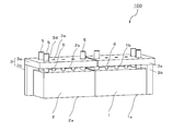
- FIG. 2 is a perspective view of a base and a holder that constitute the spectroscope shown in FIG. 1.
- FIG. 3 is a perspective view illustrating a posture adjusting mechanism including a posture adjusting member and the spectroscope illustrated in FIG. 2. It is a schematic diagram showing the manufacturing method of the spectroscope of this embodiment.
- FIG. 1 is a schematic diagram illustrating an example of an astronomical telescope including the spectroscope of the present embodiment.
- the astronomical telescope 10 has a slit 20 for restricting and transmitting an external electromagnetic wave W, a lens 30 for parallelizing the electromagnetic wave W passing through the slit 20, and gold for reflecting the parallelized electromagnetic wave W on its surface.
- a base material (1) provided with a coated mirror 40 and a diffraction grating (not shown in FIG. 1) which is arranged in series with the holder 3 shifted in the width direction and is arranged to separate reflected electromagnetic waves W by wavelength. 2), a holder 3 for fixing the base materials (1, 2), a lens group 70 sequentially arranged along the optical path of the light spectrum, and a detector (infrared array) 80.
- These components are accommodated in a low-temperature holding mechanism 90 having a window to suppress temperature fluctuation.
- the spectroscope in FIG. 1 includes a substrate (1, 2) and a holder 3.
- the electromagnetic wave W incident from the outside of the low-temperature holding mechanism 90 toward the spectroscope travels along the optical path, is reflected by the first surface 1a and the third surface 2a, and becomes a reflected wave separated for each wavelength.
- the reflected wave is imaged by the detector 80, and the information of the observation target can be analyzed.
- FIG. 2 is a perspective view of a base and a holder constituting the spectroscope shown in FIG.
- the base materials (1, 2) include a first base material 1 and a second base material 2 each having a rectangular parallelepiped shape.
- the first base material 1 and the second base material 2 are, for example, rectangular parallelepipeds each having a length of 190 mm to 210 mm, a height of 50 mm to 70 mm, and a width of 50 mm to 70 mm.
- the first substrate 1 has a first surface 1a on which a diffraction grating is formed and a second surface 1b which is a back surface thereof, and the second substrate 2 has a third surface 2a on which a diffraction grating is formed. And a fourth surface 2b which is a back surface thereof.
- the substrates (1, 2) are housed in the holder 3 so that the first surface 1a and the third surface 2a are exposed, and are fixed in a state of being shifted in the width direction in series.
- the angle between the first surface 1a and the third surface 2a indicating the relative position between the first base material 1 and the second base material 2 is three-dimensional (three different directions and three different planes). Thus, for example, adjustment in 2 seconds or less is required.
- the holder 3 includes a lid 3a facing the second surface 1b and the fourth surface 2b, and four side plates 3b supporting the lid 3a.
- the first surface 1a and the third surface 2a are open, An internal space for accommodating the first base material 1 and the second base material 2 is provided.
- the lid 3a may be composed of a plurality of plates.
- the holder 3 may be made by combining the lid 3a and the four side plates 3b separately, or may be made integrally. Further, the holder 3 has a fastener (not shown) for fixing the first base material 1 and the second base material 2 so as to cover a part of the outer edge of each of the first surface 1a and the third surface 2a. It may be attached.
- FIG. 2 shows the rectangular parallelepiped first base material 1 and the rectangular parallelepiped second base material 2, but the shape of the base materials (1, 2) is not limited thereto.
- the lid 3a and the side plate 3b are fixed by, for example, forming a coil insert (not shown) on the lid 3a or the side plate 3b, inserting a bolt (not shown) into the coil insert, and fastening.
- the material of the bolt is a low thermal expansion metal such as, for example, iron-36 wt% nickel alloy (trade name is Invar), iron-32 wt% nickel-4 wt% cobalt alloy (trade name is Super Invar).
- the lid 3a has a first hole 3d and a second hole 3e facing the fourth surface 2b, and adjusts the position of the second base material 2 according to the position of the first base material 1.
- the position adjustment member 5 is disposed through the first hole 3d, and the fixing member 6 is disposed in the second hole 3e.
- a plurality of first holes 3d and a plurality of second holes 3e may be provided.
- the hole for passing the posture adjusting member 5 and the hole for disposing the fixing member 6 may be formed in the side plate 3b.
- the posture adjusting member 5 has a function of adjusting at least one of the position and the angle of the second grating 2 according to the position and the angle of the first grating 1 before fixing the second grating 2 to the holder 3.
- the posture adjusting member 5 can also function as a member for lifting the second grating 2.
- the tip side may be directly bonded to the second grating 2 with an adhesive, and the side opposite to the tip may be fastened to a plate-like member described later with a bolt or the like.
- the fixing member 6 connects the fourth surface 2b of the second base member 2 and the lid 3a, and fixes the second base member 2 in a non-contact manner with the holder 3.
- the shape of the fixing member 6 is, for example, cylindrical or columnar, and is preferably made of the same material as the holder 3.
- the first base material 1 and the second base material 2 are configured such that the angle between both reflected waves when the parallel electromagnetic wave W is incident is, for example, within 2 seconds, and preferably within 1 second.
- the positions and angles of the first surface 1a and the third surface 2a are adjusted.
- the second base member 2 can be accurately fixed by using the fixing member 6.
- the outer surface of the side plate 3b surrounding the first surface a and the third surface 2a is mainly made of acrylic resin. It may have a black film as a component. Note that the outer surface of the holder 3 may have a black coating other than the portion surrounding the first surface 1a and the third surface 2a.
- the inner surface of the holder 3 may have a black coating mainly composed of acrylic resin from the first surface 1a and the third surface 2a to at least 1 mm in the depth direction.
- the black coating mainly composed of acrylic resin has low reflectance from the ultraviolet region to the near-infrared region, the absorption efficiency of electromagnetic waves W that is partially scattered by the diffraction grating and becomes noise increases, and the accuracy of analysis is improved. Can be higher. In particular, when the surface of the ceramic exhibits a bright color, the effect is high.
- the acrylic resin contained in the film may be identified using a Fourier transform infrared spectrophotometer (FTIR).
- FTIR Fourier transform infrared spectrophotometer
- the black coating may contain magnesium, aluminum and silicon in addition to the acrylic resin, and the total content of these elements is preferably 1% by mass or less.
- the first base material 1 and the second base material 2 are preferably glass having an average coefficient of linear expansion at 40 ° C. to 400 ° C. within ⁇ 2 ⁇ 10 ⁇ 6 / K.
- the holder 3 and the fixing member 6 are ceramics having an average linear expansion coefficient of ⁇ 2 ⁇ 10 ⁇ 6 / K at 40 ° C. to 400 ° C. at a use temperature (for example, room temperature).
- Ceramics include ceramics containing cordierite, lithium aluminosilicate, potassium zirconium phosphate or mullite as a main component.
- the base material (1, 2), the holder 3 and the fixing member 6 are made of such a low thermal expansion material, the shape change is small even when exposed to a temperature change. Has high reliability.
- Ceramics containing cordierite as a main component Ca is 0.4% by mass to 0.6% by mass in terms of CaO, Al is 2.3% by mass to 3.5% by mass in terms of Al 2 O 3 , and Mn is Mn. And Cr may be contained in an amount of 0.6% by mass or more and 0.7% by mass or less in terms of MnCr 2 O 4 .
- This ceramic can have an average coefficient of linear expansion of ⁇ 20 ⁇ 10 ⁇ 9 / K or less.
- the ceramic containing lithium aluminosilicate as a main component may contain 20% by mass or less of silicon carbide.
- a glass containing titanium silicate as a main component is cited.
- the average linear expansion coefficient may be obtained in accordance with JIS R # 1618: 2002.
- the average linear expansion coefficient may be determined in accordance with JIS R # 3251: 1995.
- the measurement may be performed using an optical heterodyne method 1 optical path interferometer.
- the main component in the ceramics refers to a component that accounts for 60% by mass or more of the total 100% by mass of the components constituting the target ceramics.
- the components constituting the ceramic may be identified by using an X-ray diffractometer (XRD).
- XRD X-ray diffractometer
- the content of each component can be determined by identifying the component, calculating the content of the element constituting the component by using an X-ray fluorescence spectrometer (XRF) or an ICP emission spectrometer, and converting it to the identified component.
- XRF X-ray fluorescence spectrometer
- ICP emission spectrometer ICP emission spectrometer
- a first substrate 1 having a first surface 1a on which a diffraction grating is formed and a second surface 1b which is a back surface of the first surface 1a, and a third surface 2a and a third surface on which a diffraction grating is formed
- a second base material 2 having a fourth surface 2b, which is the back surface of 2a, is prepared.
- the outer surface of the frame body may be covered with a black paint by applying a black paint mainly composed of an acrylic resin diluted with an organic solvent to the outer surface positioned as described above and drying the same.
- a black paint mainly composed of an acrylic resin diluted with an organic solvent is applied to the inner surface of the frame from the first surface 1a and the third surface 2a to at least 1 mm in the depth direction and dried.
- a black paint mainly composed of an acrylic resin diluted with an organic solvent is applied to the inner surface of the frame from the first surface 1a and the third surface 2a to at least 1 mm in the depth direction and dried.
- the inner surface of the frame-shaped body in the above range may be covered with a black paint.
- the mixing ratio between the black paint and the organic solvent is 1: 1 by mass
- the drying temperature is 60 ° C. or more and 80 ° C. or less
- the drying time is 15 minutes or more and 25 minutes or less.
- the first base material 1 is placed in the internal space of the holder 3 so that the second surface 1b is on the side of the lid 3a, and the lid 3a is formed into a frame. Connecting.
- the connection between the frame-shaped body and the lid 3a can be performed by inserting and fastening bolts (not shown) into coil inserts formed in advance on the lid 3a or the side plate 3b.
- the first base material 1 is fixed to the holder 3 via the fixing member 6 by using an adhesive (for example, an epoxy adhesive manufactured by 3M Scotch Weld, SW9323).
- the fixing member 6 for fixing the first base 1 is, for example, the same shape and the same material as the fixing member 6 for fixing the second base 2.
- the second base material 2 is inserted from the opening of the frame-shaped body such that the fourth surface 2b is on the side of the lid 3a, and the first base material 1a and the third surface 2a are exposed side by side.
- the two substrates 2 are arranged in the frame, and the lid 3a is connected to the frame.
- the connection between the lid 3a and the frame can be made in the same manner as in the case of the lid 3a facing the first base material 1.
- FIG. 3 is a perspective view showing the posture adjusting mechanism 4 including the posture adjusting member 5 and the spectroscope shown in FIG.
- the posture adjusting member 5 is attached to the fourth surface 2b through the first hole 3d.
- a part of the side plate 3b is not shown as in FIG.
- a clearance for adjusting the posture is provided between the posture adjusting member 5 and the first hole 3d.
- the posture adjusting member 5 is a columnar member inserted into each of the plurality of first holes 3d.
- the posture adjusting mechanism 4 includes a posture adjusting member 5, a plate-like member 7 fastened to the posture adjusting member 5, and a movable member 8 for adjusting the posture of the plate-like member 7 by rotating. The position and angle of the second base member 2 with respect to the fixed first base member 1 are adjusted three-dimensionally.
- micrometer heads 8a which are examples of a movable member 8 that can adjust the position and angle of the second base member 2 in a first direction (gravity direction).
- Two micrometer heads 8b capable of adjusting the position and angle in a direction perpendicular to the first direction.
- a differential micrometer head SHSP-19
- the posture adjusting member 5 may be bonded directly to the second base material 2 with an adhesive on the front end side, and fastened to the plate-shaped member 7 on the side opposite to the front end by bolts or the like.
- the angle formed by the reflected waves of the first base material 1 and the second base material 2 when the parallel electromagnetic waves W are incident using the attitude adjustment member 5 is, for example, within 1 second or 0. Adjust so that it is within 1 second.
- He-Ne laser light is incident on the first surface 1a and the third surface 2a, and the interference fringes of both reflected waves are confirmed by an optical interferometer while turning the fine adjustment screw of the micrometer head.
- a position where the stripes are aligned is a fixing position of the second base material 2.
- the fixing member 6 is arranged between the fourth surface 2b and the second hole 3e of the second base material, and the fourth surface 2b and the fixing member 6, and the fixing member 6 and the second hole 3e are connected.
- the second base member 2 is fixed to the holder 3 via an adhesive (for example, an epoxy adhesive manufactured by 3M @ scotch @ weld, SW9323) between the inner base and the inner peripheral surface to be formed (FIG. 4C).
- the spectroscope shown in FIG. 2 is obtained by removing the attitude adjusting member 5 from the second base material 2.
- the angle of the second base member 2 with respect to the first base member 1 is slightly reduced, but can be kept within 2 seconds.
- the posture adjusting member 5 is removed after the second base member 2 is adjusted and fixed, but the columnar portion of the posture adjusting member 5 may be left as it is.
Landscapes
- Physics & Mathematics (AREA)
- Spectroscopy & Molecular Physics (AREA)
- General Physics & Mathematics (AREA)
- Optics & Photonics (AREA)
- Astronomy & Astrophysics (AREA)
- Spectrometry And Color Measurement (AREA)
- Diffracting Gratings Or Hologram Optical Elements (AREA)
Abstract
Priority Applications (5)
| Application Number | Priority Date | Filing Date | Title |
|---|---|---|---|
| EP19830321.6A EP3819614A4 (fr) | 2018-07-02 | 2019-07-01 | Spectroscope, télescope et procédé de fabrication de spectroscope |
| US17/255,896 US20210333500A1 (en) | 2018-07-02 | 2019-07-01 | Spectroscope, astronomical telescope and method for manufacturing spectroscope |
| KR1020207036723A KR20210013139A (ko) | 2018-07-02 | 2019-07-01 | 분광기, 천체망원경 및 분광기의 제조 방법 |
| JP2020528852A JP7223756B2 (ja) | 2018-07-02 | 2019-07-01 | 分光器、天体望遠鏡および分光器の製造方法 |
| CN201980042501.7A CN112400100A (zh) | 2018-07-02 | 2019-07-01 | 分光器、天体望远镜以及分光器的制造方法 |
Applications Claiming Priority (2)
| Application Number | Priority Date | Filing Date | Title |
|---|---|---|---|
| JP2018126124 | 2018-07-02 | ||
| JP2018-126124 | 2018-07-02 |
Publications (1)
| Publication Number | Publication Date |
|---|---|
| WO2020009061A1 true WO2020009061A1 (fr) | 2020-01-09 |
Family
ID=69060354
Family Applications (1)
| Application Number | Title | Priority Date | Filing Date |
|---|---|---|---|
| PCT/JP2019/026101 Ceased WO2020009061A1 (fr) | 2018-07-02 | 2019-07-01 | Spectroscope, télescope et procédé de fabrication de spectroscope |
Country Status (6)
| Country | Link |
|---|---|
| US (1) | US20210333500A1 (fr) |
| EP (1) | EP3819614A4 (fr) |
| JP (1) | JP7223756B2 (fr) |
| KR (1) | KR20210013139A (fr) |
| CN (1) | CN112400100A (fr) |
| WO (1) | WO2020009061A1 (fr) |
Citations (8)
| Publication number | Priority date | Publication date | Assignee | Title |
|---|---|---|---|---|
| JPS4527426B1 (fr) * | 1966-08-26 | 1970-09-08 | ||
| US5172390A (en) * | 1989-04-20 | 1992-12-15 | Massachusetts Institute Of Technology | Pre-aligned diode laser for external cavity operation |
| JPH0694527A (ja) | 1992-09-10 | 1994-04-05 | Nikon Corp | 分光光学系 |
| JPH06331850A (ja) * | 1993-05-25 | 1994-12-02 | Matsushita Electric Ind Co Ltd | 光フィルタおよび光フィルタに用いる回折素子 |
| JP2003255206A (ja) * | 2002-02-28 | 2003-09-10 | Ando Electric Co Ltd | 平面回折格子の調整機構及びその製造方法 |
| JP2004280116A (ja) * | 2003-03-18 | 2004-10-07 | Lucent Technol Inc | 光学格子マウント |
| WO2006075400A1 (fr) * | 2005-01-17 | 2006-07-20 | Mitsubishi Denki Kabushiki Kaisha | Dispositif d’alignement de réseau de diffraction de segment |
| JP2019012030A (ja) * | 2017-06-30 | 2019-01-24 | 京セラ株式会社 | 分光器 |
Family Cites Families (14)
| Publication number | Priority date | Publication date | Assignee | Title |
|---|---|---|---|---|
| US5040889A (en) * | 1986-05-30 | 1991-08-20 | Pacific Scientific Company | Spectrometer with combined visible and ultraviolet sample illumination |
| JPH01277727A (ja) * | 1988-04-30 | 1989-11-08 | Shimadzu Corp | 回折格子分光器 |
| JP3719811B2 (ja) * | 1997-03-27 | 2005-11-24 | ソマール株式会社 | 反射防止フィルム |
| JP2001343286A (ja) * | 2000-05-31 | 2001-12-14 | Shimadzu Corp | ミラーユニット及びこれを用いた光分析装置 |
| JP4556620B2 (ja) * | 2004-11-02 | 2010-10-06 | 株式会社ニコン | 分光装置 |
| US7936455B2 (en) * | 2007-10-05 | 2011-05-03 | Burt Jay Beardsley | Three mirror anastigmat spectrograph |
| CN201322813Y (zh) * | 2008-11-26 | 2009-10-07 | 中国科学院上海光学精密机械研究所 | 拼接光栅位移偏差监测系统 |
| US8390806B1 (en) * | 2009-05-21 | 2013-03-05 | Lockheed Martin Corporation | MEMS spectrometer and sensing systems therefrom |
| CN101699328B (zh) * | 2009-10-28 | 2011-04-13 | 中国科学院安徽光学精密机械研究所 | 一种空间外差干涉仪中光栅胶合的装调机构 |
| JP5873775B2 (ja) * | 2012-07-25 | 2016-03-01 | 株式会社日立ハイテクノロジーズ | 回折格子ホルダ、回折格子評価装置、および測定装置 |
| US8873050B1 (en) * | 2012-08-16 | 2014-10-28 | Kla-Tencor Corp. | Selective diffraction with in-series gratings |
| US9435689B2 (en) * | 2012-10-31 | 2016-09-06 | Corning Incorporated | Hyperspectral imaging system, monolithic spectrometer and methods for manufacturing the monolithic spectrometer |
| WO2018085863A1 (fr) * | 2016-11-07 | 2018-05-11 | California Institute Of Technology | Ensemble monolithique formant spectromètre hétérodyne spatial réfléchissant |
| DE102018205401B4 (de) * | 2018-04-10 | 2022-06-15 | Fraunhofer-Gesellschaft zur Förderung der angewandten Forschung e.V. | Spektralanalysesystem zum Aufnehmen eines Spektrums |
-
2019
- 2019-07-01 WO PCT/JP2019/026101 patent/WO2020009061A1/fr not_active Ceased
- 2019-07-01 EP EP19830321.6A patent/EP3819614A4/fr not_active Withdrawn
- 2019-07-01 KR KR1020207036723A patent/KR20210013139A/ko not_active Withdrawn
- 2019-07-01 US US17/255,896 patent/US20210333500A1/en not_active Abandoned
- 2019-07-01 JP JP2020528852A patent/JP7223756B2/ja active Active
- 2019-07-01 CN CN201980042501.7A patent/CN112400100A/zh active Pending
Patent Citations (8)
| Publication number | Priority date | Publication date | Assignee | Title |
|---|---|---|---|---|
| JPS4527426B1 (fr) * | 1966-08-26 | 1970-09-08 | ||
| US5172390A (en) * | 1989-04-20 | 1992-12-15 | Massachusetts Institute Of Technology | Pre-aligned diode laser for external cavity operation |
| JPH0694527A (ja) | 1992-09-10 | 1994-04-05 | Nikon Corp | 分光光学系 |
| JPH06331850A (ja) * | 1993-05-25 | 1994-12-02 | Matsushita Electric Ind Co Ltd | 光フィルタおよび光フィルタに用いる回折素子 |
| JP2003255206A (ja) * | 2002-02-28 | 2003-09-10 | Ando Electric Co Ltd | 平面回折格子の調整機構及びその製造方法 |
| JP2004280116A (ja) * | 2003-03-18 | 2004-10-07 | Lucent Technol Inc | 光学格子マウント |
| WO2006075400A1 (fr) * | 2005-01-17 | 2006-07-20 | Mitsubishi Denki Kabushiki Kaisha | Dispositif d’alignement de réseau de diffraction de segment |
| JP2019012030A (ja) * | 2017-06-30 | 2019-01-24 | 京セラ株式会社 | 分光器 |
Non-Patent Citations (1)
| Title |
|---|
| See also references of EP3819614A4 |
Also Published As
| Publication number | Publication date |
|---|---|
| JPWO2020009061A1 (ja) | 2021-07-15 |
| KR20210013139A (ko) | 2021-02-03 |
| EP3819614A4 (fr) | 2022-04-13 |
| US20210333500A1 (en) | 2021-10-28 |
| CN112400100A (zh) | 2021-02-23 |
| JP7223756B2 (ja) | 2023-02-16 |
| EP3819614A1 (fr) | 2021-05-12 |
Similar Documents
| Publication | Publication Date | Title |
|---|---|---|
| US8861060B2 (en) | Spectral decomposition device and manufacturing the same | |
| US8120853B2 (en) | Optical assembly, method for assembling an optical assembly, system for securing optical elements of an optical assembly and a spring for securing optical elements of an optical assembly | |
| US4142797A (en) | Common path interferometer | |
| Szentgyorgyi et al. | Hectochelle: a multiobject optical echelle spectrograph for the MMT | |
| CN101871816B (zh) | 模块化分体式Sagnac干涉仪 | |
| US11237056B2 (en) | Monolithic assembly of reflective spatial heterodyne spectrometer | |
| US8081319B2 (en) | Adjustable two dimensional lamellar grating | |
| JP7223756B2 (ja) | 分光器、天体望遠鏡および分光器の製造方法 | |
| US10520361B2 (en) | Spectral analysis system for capturing a spectrum | |
| CN100425958C (zh) | 分光镜 | |
| JP2011247655A (ja) | 分光器およびこれを用いた光スペクトラムアナライザ | |
| JP7241859B2 (ja) | スライスミラー、面分光器、望遠鏡およびスライスミラーの製造方法 | |
| RU2399935C2 (ru) | Интерференционный светофильтр с перестраиваемой полосой пропускания | |
| JP6809991B2 (ja) | 分光器 | |
| Ikeda et al. | Diamond-machined ZnSe immersion grating for NIR high-resolution spectroscopy | |
| US11802796B2 (en) | Monolithic assembly of miniature reflective cyclical spatial heterodyne spectrometer interferometry systems | |
| CN114964497A (zh) | 基于超构表面与平面反射镜相结合的光谱仪及其部署方法 | |
| US6836333B1 (en) | Fourier transform spectrometer using an optical block | |
| CN112229811A (zh) | 背对背式光谱仪布置结构 | |
| JPWO2019235566A1 (ja) | 固定器具、光学装置、および光学装置の製造方法 | |
| Heijmans et al. | Design and development of the high-resolution spectrograph HERMES and the unique volume phase holographic gratings | |
| Bétrémieux et al. | Description and ray-tracing simulations of HYPE: a far-ultraviolet polarimetric spatial-heterodyne spectrometer | |
| Huber | Micromechanical tunable Fabry-Pérot interferometers with membrane Bragg mirrors based on silicon/silicon carbonitride | |
| Liu et al. | Fabrication of the convex blazed grating | |
| JP5411266B2 (ja) | フーリエ変換型x線分光装置 |
Legal Events
| Date | Code | Title | Description |
|---|---|---|---|
| 121 | Ep: the epo has been informed by wipo that ep was designated in this application |
Ref document number: 19830321 Country of ref document: EP Kind code of ref document: A1 |
|
| ENP | Entry into the national phase |
Ref document number: 2020528852 Country of ref document: JP Kind code of ref document: A |
|
| ENP | Entry into the national phase |
Ref document number: 20207036723 Country of ref document: KR Kind code of ref document: A |
|
| NENP | Non-entry into the national phase |
Ref country code: DE |
|
| ENP | Entry into the national phase |
Ref document number: 2019830321 Country of ref document: EP Effective date: 20210202 |