WO2020009074A1 - Dispositif d'application de force antagoniste pour volant de direction - Google Patents
Dispositif d'application de force antagoniste pour volant de direction Download PDFInfo
- Publication number
- WO2020009074A1 WO2020009074A1 PCT/JP2019/026171 JP2019026171W WO2020009074A1 WO 2020009074 A1 WO2020009074 A1 WO 2020009074A1 JP 2019026171 W JP2019026171 W JP 2019026171W WO 2020009074 A1 WO2020009074 A1 WO 2020009074A1
- Authority
- WO
- WIPO (PCT)
- Prior art keywords
- shaft
- steering
- steering wheel
- reaction force
- steering shaft
- Prior art date
- Legal status (The legal status is an assumption and is not a legal conclusion. Google has not performed a legal analysis and makes no representation as to the accuracy of the status listed.)
- Ceased
Links
Images




Classifications
-
- B—PERFORMING OPERATIONS; TRANSPORTING
- B62—LAND VEHICLES FOR TRAVELLING OTHERWISE THAN ON RAILS
- B62D—MOTOR VEHICLES; TRAILERS
- B62D5/00—Power-assisted or power-driven steering
- B62D5/001—Mechanical components or aspects of steer-by-wire systems, not otherwise provided for in this maingroup
- B62D5/005—Mechanical components or aspects of steer-by-wire systems, not otherwise provided for in this maingroup means for generating torque on steering wheel or input member, e.g. feedback
- B62D5/006—Mechanical components or aspects of steer-by-wire systems, not otherwise provided for in this maingroup means for generating torque on steering wheel or input member, e.g. feedback power actuated
-
- F—MECHANICAL ENGINEERING; LIGHTING; HEATING; WEAPONS; BLASTING
- F16—ENGINEERING ELEMENTS AND UNITS; GENERAL MEASURES FOR PRODUCING AND MAINTAINING EFFECTIVE FUNCTIONING OF MACHINES OR INSTALLATIONS; THERMAL INSULATION IN GENERAL
- F16H—GEARING
- F16H1/00—Toothed gearings for conveying rotary motion
- F16H1/02—Toothed gearings for conveying rotary motion without gears having orbital motion
- F16H1/20—Toothed gearings for conveying rotary motion without gears having orbital motion involving more than two intermeshing members
- F16H1/22—Toothed gearings for conveying rotary motion without gears having orbital motion involving more than two intermeshing members with a plurality of driving or driven shafts; with arrangements for dividing torque between two or more intermediate shafts
-
- B—PERFORMING OPERATIONS; TRANSPORTING
- B62—LAND VEHICLES FOR TRAVELLING OTHERWISE THAN ON RAILS
- B62D—MOTOR VEHICLES; TRAILERS
- B62D5/00—Power-assisted or power-driven steering
- B62D5/001—Mechanical components or aspects of steer-by-wire systems, not otherwise provided for in this maingroup
- B62D5/003—Backup systems, e.g. for manual steering
Definitions
- the present invention relates to a steering wheel reaction force applying device incorporated in a steer-by-wire type steering system.
- the steer-by-wire steering system includes a steering device having a steering wheel, and a steering device electrically connected to the steering device for imparting a steering angle to a pair of steered wheels.
- the steering device further includes a sensor for detecting an operation amount of a steering wheel, and applies a steering angle to a pair of steered wheels by driving an actuator of the steering device based on an output signal of the sensor. I do.
- the steer-by-wire steering system has an advantage that the steering angle of the steered wheels with respect to the operation amount of the steering wheel can be adjusted according to the traveling speed of the vehicle.
- the degree of freedom in designing the steering system can be improved, and parts are shared between the right-hand drive vehicle and the left-hand drive vehicle. be able to.
- the steering system of the steer-by-wire system is configured to apply an operation reaction force to the steering wheel by an electric motor.
- the steering system described in Japanese Patent Application Laid-Open No. 2007-55453 is configured to directly apply the power of the electric motor to the steering shaft without going through a speed reduction mechanism or the like. In such a structure of the direct drive system, there is a problem that the size of the electric motor is increased.
- the output shafts of a pair of electric motors are arranged in parallel with the steering shaft, and the respective powers of the electric motors are steered via two-stage gears. It is configured to be applied to a shaft. Specifically, each large-diameter side tooth portion of the two-stage gear meshes with a motor-side tooth portion disposed on the output shaft of the electric motor, and each small-diameter side tooth portion of the two-stage gear is connected to a steering shaft. And meshed with the shaft-side teeth arranged in the shaft.
- the present invention has been made in view of the above circumstances, and has as its object to realize a structure of a reaction force applying device for a steering wheel, which can be made compact.
- a reaction force applying device for a steering wheel includes a steering shaft, an electric motor, and at least one two-stage gear.
- the steering shaft has a shaft-side tooth portion.
- the electric motor has an output shaft arranged coaxially with the steering shaft, and a motor-side tooth portion provided at a tip end of the output shaft.
- the at least one two-stage gear includes an intermediate shaft disposed parallel to the steering shaft, a first tooth portion disposed on the intermediate shaft and meshing with the shaft side tooth portion, And a second tooth portion that is disposed closer to the electric motor than the first tooth portion and that meshes with the motor-side tooth portion.
- the at least one two-stage gear is preferably constituted by a plurality of two-stage gears, and more preferably constituted by three two-stage gears.
- the at least one two-stage gear may be constituted by two or four or more two-stage gears, or may be constituted by one two-stage gear.
- the reaction force imparting device for a steering wheel according to the present invention may further include an urging mechanism for urging the at least one two-stage gear inward in the radial direction of the steering shaft.
- the at least one two-stage gear is constituted by the plurality of two-stage gears, the urging is performed on at least one of the plurality of two-stage gears.
- a mechanism can be provided.
- the intermediate shaft can be a torsion bar, and the intermediate shaft can exert torsional elasticity in a state where torque is not transmitted by the at least one two-stage gear.
- the at least one two-stage gear may further include a stopper mechanism for preventing the first tooth portion and the second tooth portion from rotating relative to each other by a predetermined angle or more.
- the intermediate shaft of at least one of the plurality of two-stage gears is used.
- a torsion bar is provided so that the intermediate shaft exerts a torsional elasticity in a state where torque is not transmitted by the at least one two-stage gear.
- the vehicle further includes an axis aligning unit that aligns the steering shaft with the output shaft.
- the shaft aligning portion is provided in a recess provided in one of the steering shaft and the output shaft, and is provided in the other of the steering shaft and the output shaft, and is disposed on an inner diameter side of the recess. And a sleeve disposed between the inner peripheral surface of the concave portion and the outer peripheral surface of the convex portion without play in the radial direction.
- the shaft aligning portion is provided in a recess provided in one of the steering shaft and the output shaft, and provided in the other of the steering shaft and the output shaft, and is provided on an inner diameter side of the recess.
- a plurality of rolling elements rotatably arranged between the inner peripheral surface of the concave portion and the outer peripheral surface of the convex portion.
- the shaft aligning portion is provided in one of the steering shaft and the output shaft, and the other is provided in the steering shaft and the output shaft. It is possible to provide a convex portion which is fitted inside so as to be able to perform relative rotation without rattling.
- the output shaft of the electric motor is arranged coaxially with the steering shaft, the overall size of the device can be reduced.
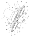
- FIG. 1 is a perspective view showing a reaction force applying device for a steering wheel according to a first example of an embodiment of the present invention.
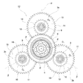
- FIG. 2 is a perspective view of a steering wheel reaction force applying device according to a first example of the embodiment of the present invention, in which a speed reduction mechanism is taken out and shown.
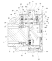
- FIG. 3 is an end view seen from the left side of FIG.
- FIG. 4 is an enlarged cross-sectional view of a main part, illustrating a steering wheel reaction force applying device according to a first example of an embodiment of the present invention.
- FIG. 5 is a perspective view of a steering wheel reaction force applying device according to a second embodiment of the present invention, in which a two-stage gear is taken out and shown.
- FIG. 1 is a perspective view showing a reaction force applying device for a steering wheel according to a first example of an embodiment of the present invention.
- FIG. 2 is a perspective view of a steering wheel reaction force applying device according to a first example of the embodiment of the present invention,
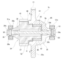
- FIG. 6 is a cross-sectional view of a steering wheel reaction force applying device according to a second example of the embodiment of the present invention, in which a two-stage gear is taken out and shown.
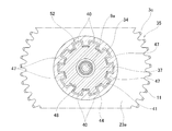
- FIG. 7 is a sectional view taken along line XX of FIG.
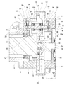
- FIG. 8 is an enlarged sectional view of a main part showing a steering wheel reaction force applying device according to a third example of an embodiment of the present invention.
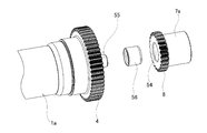
- FIG. 9 is an exploded perspective view illustrating a steering wheel reaction force applying apparatus according to a third embodiment of the present invention, in which a steering shaft, an output shaft of an electric motor, and a sleeve are taken out.
- FIG. 10 is an enlarged sectional view of a main part, showing a steering wheel reaction force applying device according to a fourth example of an embodiment of the present invention.
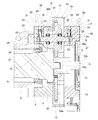
- FIG. 11 is an enlarged sectional view of a main part showing a steering wheel reaction force applying device according to a fifth example of an embodiment of the present invention.
- FIG. 12 is an enlarged sectional view of a main part, showing a steering wheel reaction force applying device according to a sixth example of an embodiment of the present invention.
- the steering wheel reaction force applying device of the present embodiment includes a steering shaft 1, an electric motor 2, and three two-stage gears 3a and 3b.
- the steering shaft 1 has the shaft side teeth 4.
- the shaft-side teeth portion 4 is provided at a tip portion (a front end portion; a right end portion in FIGS. 1, 2, and 4) of the steering shaft 1.
- the shaft side teeth 4 are arranged coaxially with the steering shaft 1 and rotate integrally with the steering shaft 1.
- the shaft side tooth portion 4 has a predetermined pitch circle diameter and a predetermined number of teeth.
- the steering shaft 1 is rotatably supported via a rolling bearing 6 on the inner diameter side of a steering column 5 supported on the vehicle body.
- a steering wheel (not shown) is attached to a rear end (left end in FIG. 1) of the steering shaft 1 which projects rearward from a rear end of the steering column 5.
- the electric motor 2 has an output shaft 7 arranged coaxially with the steering shaft 1, and a motor-side tooth portion 8 provided at a front end (rear end) of the output shaft 7.
- the motor-side teeth 8 are arranged coaxially with the output shaft 7 and rotate integrally with the output shaft 7.
- the motor-side teeth 8 have a smaller pitch circle diameter than the shaft-side teeth 4, and have a smaller number of teeth than the shaft-side teeth 4.
- Each of the two-stage gears 3a, 3b has an intermediate shaft 9, a first tooth portion 10, and a second tooth portion 11.
- the intermediate shaft 9 is disposed outside the steering shaft 1 in the radial direction of the steering shaft 1 and parallel to the steering shaft 1.
- the first tooth portion 10 is disposed around a portion (rear portion) on the steering shaft 1 side with respect to the axial direction of the intermediate shaft 9 so as to freely rotate around the intermediate shaft 9, and It meshes with the shaft side teeth 4.
- the first tooth portion 10 has a predetermined pitch circle diameter and a predetermined number of teeth.
- the second tooth portion 11 is arranged around a portion (front portion) on the electric motor 2 side with respect to the axial direction of the intermediate shaft 9 so as to rotate in synchronization with the first tooth portion 10, and 2 meshes with the second motor-side tooth portion 8.
- the second tooth portion 11 has a pitch circle diameter larger than the pitch circle diameter of the first tooth portion 10 and has a larger number of teeth than the number of teeth of the first tooth portion 10.
- a speed reduction mechanism 12 for reducing the power of the electric motor 2 and transmitting the power to the steering shaft 1 is configured. It is preferable that the reduction ratio between the steering shaft 1 and the output shaft 7 of the electric motor 2 is 3 or more and 6 or less.
- the speed reduction mechanism 12 is housed in the housing 13.
- the housing 13 includes a front housing element 14 disposed on the front side and a rear housing element 15 disposed on the rear side, which are connected and fixed by bolts 16.
- the electric motor 2 is supported and fixed to the front housing element 14, and the rear housing element 15 is supported and fixed to the front end of the steering column 5.
- the reaction force applying device for a steering wheel includes an urging mechanism that elastically urges one of the two-stage gears 3a and 3b inward in the radial direction of the steering shaft 1. 17 is further provided.
- the three two-stage gears 3a and 3b are arranged around the steering shaft 1 and the output shaft 7 of the electric motor 2 at irregular intervals in the circumferential direction.
- the virtual straight line ⁇ perpendicular to the central axis O a of the two-stage gear 3a is biased to the center axis O 1 and the biasing mechanism 17 of the steering shaft 1, the center axis O 1 with and of the steering shaft 1 angle between imaginary straight line beta perpendicular to the central axis O b of the two-stage gear 3b that is not biased by the energized mechanism 17 theta is smaller than the angle phi between the virtual straight line ⁇ ( ⁇ ⁇ ).
- the three two-stage gears 3a and 3b can be installed around the steering shaft 1 and the output shaft 7 of the electric motor 2 at equal intervals in the circumferential direction.
- the interval between the two-stage gears in the circumferential direction is determined according to the total number of two-stage gears, the number of teeth of the first teeth, and the number of teeth of the second teeth. .
- each of the two-stage gears 3a and 3b includes a shaft member 18 forming the intermediate shaft 9, a cylindrical member 19 having a cylindrical shape, and a pair of rolling bearings 20a and 20b.
- the shaft member 18 has a large-diameter portion 21 at an intermediate portion in the axial direction, and a pair of flat plate portions 22 projecting in the axial direction from both axial ends of the large-diameter portion 21 and having a rectangular cross-sectional shape.
- the cylindrical member 19 includes a flange portion 23 protruding radially outward at an intermediate portion in the axial direction, and a first tooth portion 10 formed on the outer peripheral surface of the steering shaft 1 side of the flange portion 23 in the axial direction. And a second tooth portion 11 formed on the outer peripheral surface of the flange portion 23.
- Each of the two-stage gears 3a, 3b has a rolling bearing 20a, 20b between an axial end on the outer peripheral surface of the large diameter portion 21 of the shaft member 18 and an axial end on the inner peripheral surface of the cylindrical member 19.
- Each is installed, and the cylindrical member 19 is rotatably supported around the axially intermediate portion of the shaft member 18.
- a deep groove ball bearing is used as the rolling bearings 20a and 20b, but a cylindrical roller bearing, a tapered roller bearing, a sliding bearing, or the like may be used.
- the cylindrical member 19 is integrally formed as a whole. However, the first member having the first tooth portion 10 and the second member having the second tooth portion 11 cannot be relatively rotated. It can also be configured by coupling.
- one of the two-stage gears 3a which is urged by the urging mechanism 17 has both ends (the flat plate portions 22) of the intermediate shaft 9 in the axial direction inside the housing 13 and the steering shaft 1 Are supported so as to be able to displace in the radial direction.
- the two-stage gear 3 a has a through hole 24 that passes through each of the flat plate portions 22 of the shaft member 18 in the radial direction.
- the housing 13 has a pair of guide holes 25, a pair of screw holes 26, and a pair of circular holes 27.
- the pair of guide holes 25 are opposed to each other, and the portions of the rear surface of the front housing element 14 and the front surface of the rear housing element 15 that match each other, that is, the positions of the steering shaft 1 in the radial direction and the circumferential direction coincide. It is formed in the part which does.
- the guide hole 25 has a major axis in a direction coinciding with the radial direction of the steering shaft 1, and a minor axis in a direction perpendicular to the radial direction (the direction of the major axis) of the steering shaft 1 and the axial direction of the shaft member 18. It has a circular cross-sectional shape.
- the pair of screw holes 26 are formed so that the outer peripheral surfaces of the front housing element 14 and the rear housing element 15 and the inner peripheral surface of the guide hole 25 communicate in the radial direction of the steering shaft 1.
- the pair of circular holes 27 are formed such that the inner peripheral surfaces of the front housing element 14 and the rear housing element 15 and the inner peripheral surface of the guide hole 25 communicate with each other in the radial direction of the steering shaft 1.
- the two-stage gear 3a supports the flat plate portion 22 inside the guide hole 25 using a support member 28 so as to be able to displace the steering shaft 1 in the radial direction.
- the support member 28 has a shaft portion 29, a head portion 30 formed at a base end portion (an upper end portion in FIG. 4) of the shaft portion 29, and a male screw portion 31 formed on an outer peripheral surface of the head portion 30. .
- the support member 28 inserts the tip portion of the shaft portion 29 into the circular hole 27, and does not rattle the middle portion of the shaft portion 29 to the through hole 24 of the flat plate portion 22 inserted inside the guide hole 25. Further, the support member 28 is inserted so as to be capable of relative displacement in the axial direction, and the male screw portion 31 is screwed into the screw hole 26. Thereby, the two-stage gear 3a is supported so as to be able to displace in the radial direction of the steering shaft 1.
- an elastic member 33 is sandwiched between a seat surface 32 of the head 30 of the support member 28 and a flat surface of the flat plate portion 22 of the two-stage gear 3a opposed to the seat surface 32,
- the elasticity of the member 33 elastically urges the two-stage gear 3a inward in the radial direction of the steering shaft 1.
- the first teeth 10 are elastically urged toward the shaft-side teeth 4
- the second teeth 11 are elastically urged toward the motor-side teeth 8.
- the biasing mechanism 17 is configured by the elastic member 33.
- the elastic member 33 is made of, for example, a torsion coil spring or rubber having a cylindrical shape.
- two of the two-stage gears 3b that are not biased by the biasing mechanism 17 support and fix both ends of the intermediate shaft 9 in the axial direction inside the housing 13.
- a rectangular hole is formed in a portion where the rear side surface of the front housing element 14 and the front side surface of the rear housing element 15 are aligned with each other, and the flat plate portion 22 of the two-stage gear 3b is formed. Inserted or pressed into the rectangular hole without play.
- the steering wheel reaction force applying device of this example drives the output shaft 7 of the electric motor 2 to rotate when the driver operates the steering wheel.
- the rotational torque of the output shaft 7 is increased by the speed reduction mechanism 12 and transmitted to the steering shaft 1, and an operation reaction force is applied to the steering wheel via the steering shaft 1.
- the magnitude of the operation reaction force applied to the steering wheel is determined according to the steering angle of the steering wheel, the torque transmitted by the steering shaft 1, and the like acquired by the sensor.
- the reaction force applying device for a steering wheel according to the present embodiment is different from a structure in which a pair of electric motors are arranged around a steering shaft as in the structure described in JP-A-2009-73334. It can be configured to be small.
- the power of the electric motor 2 is applied to the steering shaft 1 after being reduced by the reduction mechanism 12 including the motor-side teeth 8, the two-stage gears 3 a and 3 b, and the shaft-side teeth 4.
- the electric motor can be reduced in size, and a general-purpose product can be used as the electric motor 2.
- the steering wheel reaction force imparting device of the present embodiment transmits power between the motor-side teeth 8 of the output shaft 7 of the electric motor 2 and the shaft-side teeth 4 of the steering shaft 1, and has two-stage gears 3 a and 3 b.
- the power of the electric motor 2 can be distributed to the three two-stage gears 3a and 3b and transmitted to the steering shaft 1. Therefore, as compared with a structure having only one two-stage gear, the torque transmitted per one of the two-stage gears 3a and 3b can be reduced, and the outer diameter of the two-stage gears 3a and 3b can be reduced accordingly. Can be kept small (the teeth constituting the two-stage gears 3a and 3b can be made small). For this reason, the size of the reduction mechanism 12 that reduces the power of the electric motor 2 and transmits the power to the steering shaft 1 can be reduced as compared with a structure including only one two-stage gear.
- one of the two-stage gears 3a and 3b is elastically urged by the urging mechanism 17 inward in the radial direction of the steering shaft 1.
- the meshing portion between the first tooth portion 10 of the two-stage gear 3a and the shaft side tooth portion 4 of the steering shaft 1, and the second tooth portion 11 of the two-stage gear 3a and the motor side tooth of the electric motor 2 are provided.
- the backlash of the meshing part with the part 8 is suppressed. Therefore, when starting to rotate the steering shaft 1 or when changing the rotation direction of the steering shaft 1, it is possible to prevent the rattling noise from being generated at the meshing portion.
- the output shaft 7 of the steering shaft 1 and the electric motor 2 is not urged by the urging mechanism 17 by the two-stage gear 3a.
- the two two-stage gears 3b are urged toward the intermediate portion in the circumferential direction.
- the meshing portion between the first tooth portion 10 of the two-stage gear 3b and the shaft side tooth portion 4 of the steering shaft 1, and the second tooth portion 11 of the two-stage gear 3b and the motor side tooth of the electric motor 2 are formed.
- the backlash can be suppressed also at the meshing part with the part 8.
- the steering wheel reaction force applying device of the present embodiment includes three two-stage gears 3a and 3b, but the steering wheel reaction force applying device of the present invention is transmitted between the electric motor and the steering shaft. Depending on the magnitude of the power or the like, it may be configured to have only one two-stage gear. Alternatively, the reaction force imparting device for a steering wheel according to the present invention may be configured to include two or four or more two-stage gears.
- the reaction force applying device for a steering wheel moves the two-stage gear 3a only in one of the three two-stage gears 3a and 3b in the radial direction of the steering shaft 1.
- a biasing mechanism 17 that elastically biases inward is provided.
- one two-stage gear 3a Only the urging mechanism 17 is sufficient.
- an urging mechanism for elastically urging the two-stage gears inward in the radial direction of the steering shaft may be provided for two or more or all of the two-stage gears. .
- FIG. 5 to 7 show a second example of the embodiment of the present invention.
- a structure is provided that suppresses backlash existing in the meshing portion and prevents generation of rattle when starting to rotate the steering shaft 1 or changing the rotation direction of the steering shaft 1 (see FIG. 1). This is different from the steering wheel reaction force applying device according to the first example of the embodiment.
- the two-stage gear 3c having a structure for preventing generation of rattling noise is provided by connecting the first member 34 and the second member 35 to the intermediate shaft 9a as a torsion bar. , So as to be relatively rotatably connected.
- the first member 34 has a stepped cylindrical shape, and has a first small-diameter cylindrical portion 36 on the steering shaft 1 side (rear side; left side in FIGS. 5 and 6) and an electric motor 2 side (front side; FIGS.
- the first large-diameter cylindrical portion 37 (on the right side in FIG. 6) is connected by a conical cylindrical portion 38 having an outer diameter that decreases toward the steering shaft 1 side.
- the first small-diameter cylindrical portion 36 has coaxial circular holes 39a at two positions on the opposite side in the radial direction.
- the first large-diameter cylindrical portion 37 has a first tooth portion 10 that meshes with the shaft-side tooth portion 4 of the steering shaft 1 on an outer peripheral surface of a rear portion, and a radially outer portion on an outer peripheral surface of an intermediate portion. It has a male stopper portion 41 in which the inner diameter side convex portions 40 protruding in the direction are arranged at equal intervals in the circumferential direction. Furthermore, the first large-diameter cylindrical portion 37 includes an inner-diameter-side cylindrical surface portion 42 having an outer diameter that does not change in the axial direction on the outer peripheral surface of the front side portion.
- the inner diameter side cylindrical surface portion 42 has an outer diameter smaller than the root circle diameter of the male stopper portion 41, and the male stopper portion 41 has a tooth tip circle diameter smaller than the root diameter of the shaft side tooth portion 4. Having. Further, the first large-diameter cylindrical portion 37 has a single cylindrical inner peripheral surface whose inner diameter does not change in the axial direction except for the front end portion.
- the second member 35 connects the second small-diameter cylindrical portion 43 on the electric motor 2 side and the second large-diameter cylindrical portion 44 on the steering shaft 1 side by a side plate portion 45 having a substantially annular shape. .
- the second small-diameter cylindrical portion 43 has coaxial circular holes 39b at two positions on the opposite side in the radial direction.
- the second large-diameter cylindrical portion 44 has a radially outwardly protruding flange portion 23a at an axially intermediate portion, and the outer peripheral surface of the flange portion 23a is provided with a motor-side tooth portion 8 of the electric motor 2. It has a second tooth portion 11 that meshes.
- the second large-diameter cylindrical portion 44 has an outer-diameter-side cylindrical surface portion 46 having an inner diameter that does not change in the axial direction on the front-side inner peripheral surface, and has a radial- And a female stopper portion 48 in which outer-diameter-side convex portions 47 protruding from each other are arranged at equal intervals in the circumferential direction.
- the outer diameter side cylindrical surface portion 46 has an inner diameter smaller than the diameter of the addendum circle of the female stopper portion 48.
- the intermediate shaft 9a is a torsion bar that is easily twisted and deformed, and has a through hole 24a penetrating in the radial direction at both axial ends.
- the first member 34 and the second member 35 have an outer cylindrical surface portion 46 fitted on the inner cylindrical surface portion 42 via a collar 49 having a cylindrical shape so as to be relatively rotatable, and a male stopper portion.
- a collar 49 having a cylindrical shape so as to be relatively rotatable, and a male stopper portion. This is combined with the arrangement in which the inner diameter side convex portions 41 of the female stopper portion 41 and the outer diameter side convex portions 47 of the female stopper portion 48 are alternately arranged so as to be capable of a slight relative displacement in the circumferential direction.
- the collar 49 is made of a material having a small sliding resistance with respect to the inner cylindrical surface portion 42 and the outer cylindrical surface portion 46.
- a radial needle bearing may be disposed between the inner cylindrical surface portion 42 and the outer cylindrical surface portion 46.
- Both ends in the axial direction of the intermediate shaft 9a are inserted into the inner diameter side of the first small-diameter cylindrical portion 36 of the first member 34 and the inner diameter side of the second small-diameter cylindrical portion 43 of the second member 35, and
- the connecting pin 50 is inserted or press-fitted so as to bridge the through hole 24a and the circular holes 39a and 39b.
- the first member 34 and the second member 35 are connected so as to be able to rotate slightly.
- the intermediate shaft 9a exerts elasticity in the torsional direction when torque is not transmitted by the two-stage gear 3c.
- the torsional elasticity is imparted to the intermediate shaft 9a in a state where torque is not transmitted by the two-stage gear 3c.
- the two-stage gear 3c meshes the first tooth portion 10 with the shaft side tooth portion 4 in a state where the intermediate shaft 9c, which is a torsion bar, is elastically deformed in the torsional direction.
- the second teeth 11 are engaged with the motor-side teeth 8.
- the tooth surface of the shaft side tooth portion 4 and the tooth surface of the first tooth portion 10 elastically contact each other, and the tooth surface of the motor side tooth portion 8 and the tooth surface of the second tooth portion 11 are in contact with each other. Abut elastically. As a result, backlash at the engagement portion can be suppressed.
- the male member 41 of the first member 34 and the female member 48 of the second member 35 are engaged with each other via a gap in the circumferential direction.
- the second member 35 is prevented from rotating excessively relative to the second member 35. That is, in this embodiment, the stopper mechanism 52 that prevents the first tooth portion 10 and the second tooth portion 11 from relatively rotating by a predetermined angle or more by the engagement portion between the male stopper portion 41 and the female stopper portion 48. Is composed.
- the stopper mechanism 52 prevents the intermediate shaft 9a as a torsion bar from being excessively deformed in the twisting direction.
- the stopper mechanism 52 may be, for example, two positions separated in the circumferential direction of the front end surface of the first member.
- the first member disposed on the first member is engaged with the second protrusion disposed between the first protrusions in the circumferential direction on the rear end surface of the second member.
- the second member can be configured by a structure that prevents excessive relative rotation, or any other applicable known structure. The configuration and operation and effect of the other parts are the same as those of the first example of the embodiment.
- the reaction force imparting device for a steering wheel includes an axis aligning unit 53 for performing axis alignment so that the steering shaft 1a and the output shaft 7a of the electric motor 2a are coaxially arranged.
- the axis aligning portion 53 of the present example includes a concave portion 54, a convex portion 55, and a sleeve 56.
- the recess 54 is formed on the distal end surface of the output shaft 7a so as to be recessed in a direction away from the steering shaft 1a in the axial direction.
- the convex portion 55 is provided at the tip of the steering shaft 1a, and is arranged coaxially with the concave portion 54 on the inner diameter side of the concave portion 54.
- the sleeve 56 is made of a material having a small coefficient of friction with respect to a material forming the steering shaft 1a and a material forming the output shaft 7a, such as an oil-impregnated metal.
- the sleeve 56 has no play in the radial direction between the inner peripheral surface of the concave portion 54 and the outer peripheral surface of the convex portion 55, and is freely rotatable relative to at least one of the steering shaft 1a and the output shaft 7a. Are located in
- the steering wheel reaction force applying device of the present example includes the shaft aligning portion 53. Therefore, as in this example, a structure in which the steering shaft 1a is supported by the rear housing element 15 via the steering column 5 and the rolling bearing 6, and the output shaft 7a of the electric motor 2a is supported by the front housing element 14. Also in this case, good coaxiality between the steering shaft 1a and the output shaft 7a can be ensured.
- the configuration and operation and effect of the other parts are the same as those of the first and second examples of the embodiment.
- FIG. 10 shows a fourth example of the embodiment of the present invention.
- the shaft aligning portion 53a of the steering wheel reaction force applying device of the present example includes a concave portion 54a provided on the distal end surface of the steering shaft 1b, and a convex portion 55a provided on the distal end portion of the output shaft 7b of the electric motor 2b.
- the sleeve 56 is provided between the inner peripheral surface of the concave portion 54a and the outer peripheral surface of the convex portion 55b.
- the configuration and operation and effect of the other parts are the same as those of the first to third examples of the embodiment.
- FIG. 11 shows a fifth example of the embodiment of the present invention.
- the shaft aligning portion 53b of the reaction force applying device for a steering wheel according to the present embodiment includes an inner peripheral surface of a concave portion 54 provided on a distal end surface of the output shaft 7a of the electric motor 2a and a convex provided on a distal end portion of the steering shaft 1a.
- a plurality of rolling elements 58 held by a retainer 57 are arranged to be able to roll freely between the outer peripheral surface of the portion 55.
- the shaft aligning portion 53b of the third embodiment is provided between the inner peripheral surface of the concave portion 54 of the output shaft 7a and the outer peripheral surface of the convex portion 55 of the steering shaft 1a.
- a radial needle bearing including a retainer 57 and a plurality of rolling elements 58 is arranged.
- the reaction force applying device for a steering wheel of the present embodiment compared to the reaction force applying device for a steering wheel of the third example of the above-described embodiment, when the steering shaft 1a and the output shaft 7a relatively rotate. Resistance can be reduced.
- a needle is used as the rolling element 58, but a ball or a roller can also be used.
- a plurality of rollers held by a retainer are provided between an inner peripheral surface of a concave portion provided on a distal end surface of the steering shaft and an outer peripheral surface of a convex portion provided on a distal end portion of the output shaft of the electric motor.
- FIG. 12 shows a sixth example of the embodiment of the present invention.
- the shaft aligning portion 53c of the steering wheel reaction force applying device of the present example includes a concave portion 54b provided on the distal end surface of the output shaft 7c of the electric motor 2c and a convex portion 55b provided on the distal end portion of the steering shaft 1c. , And are fitted so that relative rotation is possible without play in the radial direction.
- the shaft aligning portion 53c of the present example is configured by fitting the concave portion 54b of the output shaft 7c and the convex portion 55b of the steering shaft 1c by spigot fitting.
- the number of components can be reduced as compared with the steering wheel reaction force applying device of the third example of the above-described embodiment.
- the concave portion provided on the distal end surface of the steering shaft and the convex portion provided on the distal end portion of the output shaft of the electric motor are fitted so as to be able to rotate relative to each other without play in the radial direction.
- an axis alignment unit can be configured.
- the configuration and operation and effect of the other parts are the same as those of the first and third examples of the embodiment.
- first to sixth examples of the above-described embodiment can be appropriately combined and implemented as long as no inconsistency occurs.
- the structure of the first example of the embodiment and the structure of the second example can be combined, and the structure of the fifth and sixth examples of the embodiment can be implemented by It is also possible to apply to the second example and the fourth example of the embodiment.
Landscapes
- Engineering & Computer Science (AREA)
- Mechanical Engineering (AREA)
- General Engineering & Computer Science (AREA)
- Chemical & Material Sciences (AREA)
- Combustion & Propulsion (AREA)
- Transportation (AREA)
- Power Steering Mechanism (AREA)
Abstract
La présente invention a pour objet de créer une structure pour un dispositif d'application de force antagoniste pour volant de direction qui permette une configuration compacte. Plus particulièrement, un dispositif selon l'invention comprend des engrenages à deux étages (3a, 3b), qui comprennent : un arbre intermédiaire (9) disposé en parallèle avec un arbre de direction (1); des premières dents (10) qui sont disposées sur l'arbre intermédiaire (9) et s'engrènent avec des dents côté arbre (4) sur l'arbre de direction (1) ; et des secondes dents (11) qui sont disposées sur une partie de l'arbre intermédiaire (9) qui est plus proche d'un côté moteur électrique (2) que les premières dents (10), et s'engrènent avec des dents côté moteur (8) sur le moteur électrique (2).
Priority Applications (3)
| Application Number | Priority Date | Filing Date | Title |
|---|---|---|---|
| US17/253,889 US20210269083A1 (en) | 2018-07-02 | 2019-07-01 | Reaction force applying device for a steering wheel |
| JP2020528987A JPWO2020009074A1 (ja) | 2018-07-02 | 2019-07-01 | ステアリングホイールの反力付与装置 |
| EP19830415.6A EP3819191A4 (fr) | 2018-07-02 | 2019-07-01 | Dispositif d'application de force antagoniste pour volant de direction |
Applications Claiming Priority (4)
| Application Number | Priority Date | Filing Date | Title |
|---|---|---|---|
| JP2018126295 | 2018-07-02 | ||
| JP2018-126295 | 2018-07-02 | ||
| JP2019-018476 | 2019-02-05 | ||
| JP2019018476 | 2019-02-05 |
Publications (1)
| Publication Number | Publication Date |
|---|---|
| WO2020009074A1 true WO2020009074A1 (fr) | 2020-01-09 |
Family
ID=69060367
Family Applications (1)
| Application Number | Title | Priority Date | Filing Date |
|---|---|---|---|
| PCT/JP2019/026171 Ceased WO2020009074A1 (fr) | 2018-07-02 | 2019-07-01 | Dispositif d'application de force antagoniste pour volant de direction |
Country Status (4)
| Country | Link |
|---|---|
| US (1) | US20210269083A1 (fr) |
| EP (1) | EP3819191A4 (fr) |
| JP (1) | JPWO2020009074A1 (fr) |
| WO (1) | WO2020009074A1 (fr) |
Cited By (1)
| Publication number | Priority date | Publication date | Assignee | Title |
|---|---|---|---|---|
| DE102020133969A1 (de) | 2020-12-17 | 2022-06-23 | softwareinmotion GmbH | Lenksystem für ein Fahrzeug |
Families Citing this family (1)
| Publication number | Priority date | Publication date | Assignee | Title |
|---|---|---|---|---|
| DE102018122767A1 (de) * | 2018-09-17 | 2020-03-19 | Thyssenkrupp Ag | Lenksäule und Steer-by-Wire Lenksystem |
Citations (7)
| Publication number | Priority date | Publication date | Assignee | Title |
|---|---|---|---|---|
| JPH07243514A (ja) * | 1994-03-07 | 1995-09-19 | Fuji Hensokuki Kk | 歯車変速機のバックラッシ除去装置 |
| JP2005160150A (ja) * | 2003-11-21 | 2005-06-16 | Toyota Motor Corp | センサ内蔵型モータおよびそれを備えた車両用ステアリング装置 |
| JP2005299883A (ja) * | 2004-04-15 | 2005-10-27 | Omi Kogyo Co Ltd | 歯車伝動機構及び電動工具 |
| JP2007055453A (ja) | 2005-08-25 | 2007-03-08 | Nissan Motor Co Ltd | 操舵制御装置 |
| JP2009073334A (ja) | 2007-09-20 | 2009-04-09 | Calsonic Kansei Corp | ステアリングシステム |
| JP2016016803A (ja) * | 2014-07-10 | 2016-02-01 | 三井金属アクト株式会社 | パワードア開閉装置及び当該開閉装置を備えた自動車 |
| JP2017036795A (ja) * | 2015-08-10 | 2017-02-16 | Ntn株式会社 | 車両用モータ駆動装置 |
Family Cites Families (5)
| Publication number | Priority date | Publication date | Assignee | Title |
|---|---|---|---|---|
| JP4923491B2 (ja) * | 2005-09-16 | 2012-04-25 | 株式会社ジェイテクト | 車両用操舵装置 |
| JP2008120259A (ja) * | 2006-11-13 | 2008-05-29 | Jtekt Corp | 車両用操舵装置 |
| US7837002B2 (en) * | 2007-05-08 | 2010-11-23 | Jtekt Corporation | Electric power steering apparatus |
| FR3034158B1 (fr) * | 2015-03-27 | 2018-06-15 | Safran Transmission Systems | Reducteur de vitesse a deux lignes intermediaires de transmission |
| US10407094B2 (en) * | 2015-11-13 | 2019-09-10 | Nsk Ltd. | Electric power steering device and method for assembling the same |
-
2019
- 2019-07-01 EP EP19830415.6A patent/EP3819191A4/fr not_active Withdrawn
- 2019-07-01 US US17/253,889 patent/US20210269083A1/en not_active Abandoned
- 2019-07-01 JP JP2020528987A patent/JPWO2020009074A1/ja active Pending
- 2019-07-01 WO PCT/JP2019/026171 patent/WO2020009074A1/fr not_active Ceased
Patent Citations (7)
| Publication number | Priority date | Publication date | Assignee | Title |
|---|---|---|---|---|
| JPH07243514A (ja) * | 1994-03-07 | 1995-09-19 | Fuji Hensokuki Kk | 歯車変速機のバックラッシ除去装置 |
| JP2005160150A (ja) * | 2003-11-21 | 2005-06-16 | Toyota Motor Corp | センサ内蔵型モータおよびそれを備えた車両用ステアリング装置 |
| JP2005299883A (ja) * | 2004-04-15 | 2005-10-27 | Omi Kogyo Co Ltd | 歯車伝動機構及び電動工具 |
| JP2007055453A (ja) | 2005-08-25 | 2007-03-08 | Nissan Motor Co Ltd | 操舵制御装置 |
| JP2009073334A (ja) | 2007-09-20 | 2009-04-09 | Calsonic Kansei Corp | ステアリングシステム |
| JP2016016803A (ja) * | 2014-07-10 | 2016-02-01 | 三井金属アクト株式会社 | パワードア開閉装置及び当該開閉装置を備えた自動車 |
| JP2017036795A (ja) * | 2015-08-10 | 2017-02-16 | Ntn株式会社 | 車両用モータ駆動装置 |
Non-Patent Citations (1)
| Title |
|---|
| See also references of EP3819191A4 |
Cited By (1)
| Publication number | Priority date | Publication date | Assignee | Title |
|---|---|---|---|---|
| DE102020133969A1 (de) | 2020-12-17 | 2022-06-23 | softwareinmotion GmbH | Lenksystem für ein Fahrzeug |
Also Published As
| Publication number | Publication date |
|---|---|
| JPWO2020009074A1 (ja) | 2021-07-08 |
| EP3819191A4 (fr) | 2022-03-16 |
| EP3819191A1 (fr) | 2021-05-12 |
| US20210269083A1 (en) | 2021-09-02 |
Similar Documents
| Publication | Publication Date | Title |
|---|---|---|
| WO2020009075A1 (fr) | Système de direction | |
| US9802641B2 (en) | Steering system | |
| JP2002067992A (ja) | 電動パワーステアリング装置 | |
| JP7404688B2 (ja) | ウォーム減速機および電動アシスト装置 | |
| JP2010095006A (ja) | 電動式パワーステアリング装置 | |
| US20090139356A1 (en) | Variable ratio steering apparatus | |
| JP3643950B2 (ja) | 電動式舵取装置 | |
| JP2016020718A (ja) | トルク伝達部材及び駆動軸と被駆動軸との結合部 | |
| JP3658683B2 (ja) | 電動式舵取装置 | |
| JP2008173993A (ja) | 電動式パワーステアリング装置 | |
| WO2020009074A1 (fr) | Dispositif d'application de force antagoniste pour volant de direction | |
| JP7225877B2 (ja) | ウォーム減速機および電動アシスト装置 | |
| JP3765276B2 (ja) | 電動式パワーステアリング装置 | |
| JP2004149070A (ja) | 電動パワーステアリング装置及びジョイント | |
| WO2023276598A1 (fr) | Réducteur à vis sans fin | |
| WO2012086678A1 (fr) | Direction électrique | |
| JP2006151043A (ja) | 電動パワーステアリング装置 | |
| JP2008143434A (ja) | 電動式パワーステアリング装置 | |
| JP2004301265A (ja) | ウォーム支持装置及び電動パワーステアリング装置 | |
| JP2020044854A (ja) | 操舵装置 | |
| JP3624308B2 (ja) | 電動式舵取装置 | |
| JP2002154443A (ja) | 電動パワーステアリング装置 | |
| JP4151444B2 (ja) | 電動パワーステアリング装置 | |
| JP4930771B2 (ja) | 電動パワーステアリング装置 | |
| JP7673959B2 (ja) | ウォーム減速機 |
Legal Events
| Date | Code | Title | Description |
|---|---|---|---|
| 121 | Ep: the epo has been informed by wipo that ep was designated in this application |
Ref document number: 19830415 Country of ref document: EP Kind code of ref document: A1 |
|
| ENP | Entry into the national phase |
Ref document number: 2020528987 Country of ref document: JP Kind code of ref document: A |
|
| NENP | Non-entry into the national phase |
Ref country code: DE |
|
| ENP | Entry into the national phase |
Ref document number: 2019830415 Country of ref document: EP Effective date: 20210202 |