WO2020009099A1 - Dispositif de récupération par filtration et procédé de récupération par filtration - Google Patents
Dispositif de récupération par filtration et procédé de récupération par filtration Download PDFInfo
- Publication number
- WO2020009099A1 WO2020009099A1 PCT/JP2019/026251 JP2019026251W WO2020009099A1 WO 2020009099 A1 WO2020009099 A1 WO 2020009099A1 JP 2019026251 W JP2019026251 W JP 2019026251W WO 2020009099 A1 WO2020009099 A1 WO 2020009099A1
- Authority
- WO
- WIPO (PCT)
- Prior art keywords
- filtration
- holder
- liquid
- filter
- recovery
- Prior art date
- Legal status (The legal status is an assumption and is not a legal conclusion. Google has not performed a legal analysis and makes no representation as to the accuracy of the status listed.)
- Ceased
Links
- 0 C*C*C(C)(*)CNC Chemical compound C*C*C(C)(*)CNC 0.000 description 1
Images












Classifications
-
- B—PERFORMING OPERATIONS; TRANSPORTING
- B01—PHYSICAL OR CHEMICAL PROCESSES OR APPARATUS IN GENERAL
- B01D—SEPARATION
- B01D29/00—Filters with filtering elements stationary during filtration, e.g. pressure or suction filters, not covered by groups B01D24/00 - B01D27/00; Filtering elements therefor
- B01D29/01—Filters with filtering elements stationary during filtration, e.g. pressure or suction filters, not covered by groups B01D24/00 - B01D27/00; Filtering elements therefor with flat filtering elements
- B01D29/05—Filters with filtering elements stationary during filtration, e.g. pressure or suction filters, not covered by groups B01D24/00 - B01D27/00; Filtering elements therefor with flat filtering elements supported
-
- B—PERFORMING OPERATIONS; TRANSPORTING
- B01—PHYSICAL OR CHEMICAL PROCESSES OR APPARATUS IN GENERAL
- B01D—SEPARATION
- B01D29/00—Filters with filtering elements stationary during filtration, e.g. pressure or suction filters, not covered by groups B01D24/00 - B01D27/00; Filtering elements therefor
- B01D29/76—Handling the filter cake in the filter for purposes other than for regenerating
- B01D29/78—Handling the filter cake in the filter for purposes other than for regenerating for washing
-
- B—PERFORMING OPERATIONS; TRANSPORTING
- B01—PHYSICAL OR CHEMICAL PROCESSES OR APPARATUS IN GENERAL
- B01D—SEPARATION
- B01D39/00—Filtering material for liquid or gaseous fluids
- B01D39/14—Other self-supporting filtering material ; Other filtering material
- B01D39/20—Other self-supporting filtering material ; Other filtering material of inorganic material, e.g. asbestos paper, metallic filtering material of non-woven wires
- B01D39/2027—Metallic material
-
- B—PERFORMING OPERATIONS; TRANSPORTING
- B01—PHYSICAL OR CHEMICAL PROCESSES OR APPARATUS IN GENERAL
- B01D—SEPARATION
- B01D39/00—Filtering material for liquid or gaseous fluids
- B01D39/14—Other self-supporting filtering material ; Other filtering material
- B01D39/20—Other self-supporting filtering material ; Other filtering material of inorganic material, e.g. asbestos paper, metallic filtering material of non-woven wires
- B01D39/2068—Other inorganic materials, e.g. ceramics
-
- C—CHEMISTRY; METALLURGY
- C12—BIOCHEMISTRY; BEER; SPIRITS; WINE; VINEGAR; MICROBIOLOGY; ENZYMOLOGY; MUTATION OR GENETIC ENGINEERING
- C12M—APPARATUS FOR ENZYMOLOGY OR MICROBIOLOGY; APPARATUS FOR CULTURING MICROORGANISMS FOR PRODUCING BIOMASS, FOR GROWING CELLS OR FOR OBTAINING FERMENTATION OR METABOLIC PRODUCTS, i.e. BIOREACTORS OR FERMENTERS
- C12M1/00—Apparatus for enzymology or microbiology
- C12M1/12—Apparatus for enzymology or microbiology with sterilisation, filtration or dialysis means
-
- C—CHEMISTRY; METALLURGY
- C12—BIOCHEMISTRY; BEER; SPIRITS; WINE; VINEGAR; MICROBIOLOGY; ENZYMOLOGY; MUTATION OR GENETIC ENGINEERING
- C12M—APPARATUS FOR ENZYMOLOGY OR MICROBIOLOGY; APPARATUS FOR CULTURING MICROORGANISMS FOR PRODUCING BIOMASS, FOR GROWING CELLS OR FOR OBTAINING FERMENTATION OR METABOLIC PRODUCTS, i.e. BIOREACTORS OR FERMENTERS
- C12M1/00—Apparatus for enzymology or microbiology
- C12M1/26—Inoculator or sampler
- C12M1/28—Inoculator or sampler being part of container
-
- B—PERFORMING OPERATIONS; TRANSPORTING
- B01—PHYSICAL OR CHEMICAL PROCESSES OR APPARATUS IN GENERAL
- B01D—SEPARATION
- B01D2201/00—Details relating to filtering apparatus
- B01D2201/04—Supports for the filtering elements
- B01D2201/0415—Details of supporting structures
Definitions
- the present invention relates to a filtration and recovery device and a filtration and recovery method.
- a cell strainer described in Patent Document 1 As a device for filtering a liquid containing an object to be filtered, for example, a cell strainer described in Patent Document 1 is known.
- the cell strainer described in Patent Literature 1 has a filtering unit (filter) that opens upward and filters a liquid, a holding unit that holds the filtering unit in the opening, and the inside and outside of the tube when held in the tube. It has a communicating part for communicating.
- the filtration unit is disposed on the side surface and the bottom surface of the holding unit.
- An object of the present invention is to provide a filtration and recovery apparatus and a filtration and recovery method capable of easily recovering an object to be filtered.
- the filtration and recovery apparatus includes: A filtration filter having a plurality of through holes, An inlet for introducing a liquid, an outlet for discharging the liquid, and a holder having a flow path communicating the inlet and the outlet, With The filtration filter is disposed in the flow path between the inlet and the outlet of the holder.
- the filtration and recovery method of one embodiment of the present invention includes: A filtration and recovery method for filtering and recovering a liquid containing an object to be filtered, A filter having a plurality of through-holes, an inlet for introducing a liquid, an outlet for discharging the liquid, and a holder having a flow path communicating the inlet and the outlet, the filter comprising: Is disposed in the flow path between the introduction port and the discharge port of the holder, by filtering the liquid containing the object to be filtered by using a filtration and recovery device, the filtration filter, Capturing an object to be filtered; Closing the outlet of the holder of the filtration and recovery device; Introducing a liquid for recovery from the inlet of the holder of the filtration and recovery device; Recovering the object to be filtered together with the recovery liquid held in the holder of the filtration and recovery device, including.
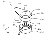
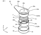
- FIG. 1 is a schematic exploded perspective view of an example of a filtration and recovery device according to a first embodiment of the present invention.
- BRIEF DESCRIPTION OF THE DRAWINGS It is a schematic sectional drawing of an example of the filtration collection
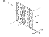
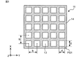
- FIG. 4 is an enlarged perspective view of a portion of an exemplary filter section. It is the schematic which looked at a part of filter part of FIG. 4 from the thickness direction.
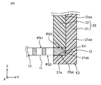
- FIG. 4 is a schematic enlarged view of a Z1 portion of the filtration and recovery device in FIG. 3.
- FIG. 3 is a diagram illustrating an example of steps of a filtration and recovery method according to the first embodiment of the present invention.
- FIG. 3 is a diagram illustrating an example of steps of a filtration and recovery method according to the first embodiment of the present invention.
- FIG. 3 is a diagram illustrating an example of steps of a filtration and recovery method according to the first embodiment of the present invention.
- FIG. 3 is a diagram illustrating an example of steps of a filtration and recovery method according to the first embodiment of the present invention.
- FIG. 3 is a diagram illustrating an example of steps of a filtration and recovery method according to the first embodiment of the present invention.
- FIG. 3 is a diagram illustrating an example of steps of a filtration and recovery method according to the first embodiment of the present invention.
- FIG. 3 is a diagram illustrating an example of steps of a filtration and recovery method according to the first embodiment of the present invention. It is a schematic structure figure of a filtration collection device of a modification of Embodiment 1 concerning the present invention. It is a schematic structure figure of an example of the filtration collection device of Embodiment 2 concerning the present invention. It is a schematic perspective view of an example of the filtration and recovery device of Embodiment 3 according to the present invention.
- FIG. 9 is a schematic exploded perspective view of an example of a filtration and recovery device according to a third embodiment of the present invention. It is a schematic sectional drawing of an example of the filtration collection
- FIG. 4 is a schematic configuration diagram of a filtration and recovery device of Comparative Example 1.
- FIG. 9 is a schematic configuration diagram of a filtration and recovery device of Comparative Example 2.
- FIG. 9 is a schematic configuration diagram of a filtration and recovery device of Comparative Example 3.
- the object to be filtered is hardly peeled off from the filter, and the object to be filtered cannot be easily collected. As a result, there is a problem that the recovery rate cannot be improved.
- the object to be filtered is a cell, the cell may be damaged by physical contact with a collecting device or the like.
- the present inventors after filtering a liquid containing an object to be filtered by a filter, immersing the object to be filtered captured by the filter in a liquid for recovery, and recovering the object to be filtered together with the liquid for recovery. It was investigated.
- the present inventors conducted filtration in a device including a filtration filter and a holder for holding the filtration filter, and then closed the discharge port of the holder, thereby collecting the liquid for collection inside the device. Found to hold.
- the present inventors when collecting the object to be filtered, by immersing the object to be filtered captured by the filter in a liquid for collection, separating the object to be filtered from the filter, a collection instrument such as a pipette To recover the object to be filtered.
- the present inventors when the object to be filtered is a cell, the present inventors generate a cell suspension by collecting the solvent together with the cells captured by the filter by using a liquid for recovery as a solvent or the like. I found that. In addition, the present inventors have found that the amount of the cell suspension to be generated is adjusted by adjusting the amount of the liquid for recovery introduced into the inside of the device.
- the filtration and recovery apparatus includes: A filtration filter having a plurality of through holes, An inlet for introducing a liquid, an outlet for discharging the liquid, and a holder having a flow path communicating the inlet and the outlet, With The filtration filter is disposed in the flow path between the inlet and the outlet of the holder.
- a protrusion protruding toward the inside of the holder is formed on an inner wall of the holder, The protrusion may hold the filtration filter.
- the filter can be held above the discharge port by the projection, and the object to be filtered can be easily collected.
- the protrusion is formed at one end of the holder provided with the discharge port,
- the filtration filter may be arranged at a position closer to the outlet than the inlet.
- the holder includes: A cylindrical first holder having the protrusion, A cylindrical second holder fitted into the first holder; Has, The filter may be sandwiched between the protrusion of the first holder and one end of the second holder.
- the first holder is a cylindrical first main body having a first end located on the inlet side of the holder and a second end located on the outlet side of the holder.
- the second holder includes a cylindrical second main body having a third end located on the inlet side of the holder and a fourth end located on the outlet side of the holder, The inner wall of the first holder and the outer wall of the second holder are in surface contact,
- the filtration filter includes a filter portion having the plurality of through holes, and a frame portion arranged to surround an outer periphery of the filter portion,
- the protrusion is provided at the second end of the first body,
- the inner wall of the first main body and the outer wall of the second main body are in surface contact,
- the frame of the filtration filter may be sandwiched between the fourth end of the second main body and an upper surface of the protrusion.
- the second holder has a flange extending from an outer wall of the second main body toward the outside of the second holder at the third end of the second main body, The flange may be in contact with the first end of the first body.
- the second holder can be easily removed from the first holder.
- the frame portion of the filtration filter is continuously extended in a direction from the filter portion toward the frame portion, and the protrusion of the first holder and the one end of the second holder are provided. And may be sandwiched in the thickness direction.
- the filtration filter can be held in the flow path of the holder in a state where the pulling force on the filtration filter in the radial direction is suppressed. As a result, breakage of the filtration filter during filtration can be suppressed.
- a liquid amount indicating unit that indicates a liquid amount of the liquid held inside the holder when the discharge port is closed may be provided on an inner wall of the holder.
- the amount of liquid to be collected can be adjusted when the object to be filtered is collected together with the liquid for collection.
- one end of the holder provided with the discharge port may be configured to make surface contact with a flat surface.
- the filtration filter includes at least one of a metal and a metal oxide as a main component, and includes a filter unit having the plurality of through-holes and a frame arranged to surround an outer periphery of the filter unit. And a unit.
- the object to be filtered can be more easily collected.
- a petri dish having a bottom surface, and a side wall formed along the outer edge of the bottom surface and extending upward from the bottom surface, and detachably attached to one end of the holder provided with the discharge port; With The bottom portion of the petri dish is disposed at one end of the holder provided with the discharge port, The side wall of the petri dish may surround an outer wall of the holder.
- the filtration and recovery method of one embodiment of the present invention includes: A filtration and recovery method for filtering and recovering a liquid containing an object to be filtered, A filter having a plurality of through-holes, an inlet for introducing a liquid, an outlet for discharging the liquid, and a holder having a flow path communicating the inlet and the outlet, the filter comprising: Is disposed in the flow path between the introduction port and the discharge port of the holder, by filtering the liquid containing the object to be filtered by using a filtration and recovery device, the filtration filter, Capturing an object to be filtered; Closing the outlet of the holder of the filtration and recovery device; Introducing a liquid for recovery from the inlet of the holder of the filtration and recovery device; Recovering the object to be filtered together with the recovery liquid held in the holder of the filtration and recovery device, including.
- the step of closing the discharge port of the holder of the filtration and collection device may include disposing one end of the holder provided with the discharge port on a bottom surface of a petri dish.
- the object to be filtered can be more easily collected.
- the inner wall of the holder of the filtration and recovery device is provided with a liquid amount indicator that indicates a liquid amount of the liquid held inside the holder in a state where the discharge port is closed.
- the step of introducing the collection liquid may include introducing the collection liquid based on the liquid amount indicating unit.
- the filtration and recovery method of one embodiment of the present invention includes: A filtration and recovery method for filtering and recovering a liquid containing an object to be filtered, A filter having a plurality of through-holes, an inlet for introducing a liquid, an outlet for discharging the liquid, and a holder having a flow path communicating the inlet and the outlet, the filter comprising: Is disposed in the flow path between the introduction port and the discharge port of the holder, by filtering the liquid containing the object to be filtered by using a filtration and recovery device, the filtration filter, Capturing an object to be filtered; Removing the filtration filter from the holder of the filtration and recovery device; Peeling the object to be filtered captured by the filtration filter with a liquid for collection, Recovering the object to be filtered together with the liquid for recovery, including.
- the filtration and recovery method of one embodiment of the present invention includes: A filtration and collection method for separating cells from cell aggregates and collecting by filtration, A filter having a plurality of through-holes, an inlet for introducing a liquid, an outlet for discharging the liquid, and a holder having a flow path communicating the inlet and the outlet, the filter comprising: Is disposed in the flow path between the inlet and the outlet of the holder, a step of introducing a cell aggregate to a filtration and recovery device, Introducing a stripping solution into the filtration and recovery device, Separating the cells from the cell aggregates by maintaining the cell aggregates immersed in the stripping solution, By discharging the stripping solution from the filtration and recovery device, capturing the cells with the filtration filter, Closing the outlet of the holder of the filtration and recovery device; Introducing a liquid for recovery from the inlet of the holder of the filtration and recovery device; Recovering the cells together with the recovery liquid held in the holder of the filtration and recovery
- the filtration and recovery method of one embodiment of the present invention includes: A filtration and recovery method for filtering and recovering a liquid containing an object to be filtered, A filter having a plurality of through-holes, an inlet for introducing a liquid, an outlet for discharging the liquid, and a holder having a flow path communicating the inlet and the outlet, the filter comprising: Is disposed in the flow path between the inlet and the outlet of the holder, a step of introducing a solvent to a filtration and recovery device, The step of capturing the object to be filtered by the filtration filter by introducing the liquid including the object to be filtered into the filtration and recovery device, Closing the outlet of the holder of the filtration and recovery device; Introducing a liquid for recovery from the inlet of the holder of the filtration and recovery device; Recovering the object to be filtered together with the recovery liquid held in the holder of the filtration and recovery device, including.
- the filtration and recovery device is a device that can perform filtration and recovery. Specifically, the filtration and recovery device filters the liquid containing the object to be filtered with a filtration filter, and then holds the recovery liquid inside the filtration and recovery device. Thereafter, the filtration target captured by the filtration filter is collected together with the collection liquid by a pipette or the like.
- the “filtration target” refers to a target to be filtered among the targets included in the liquid.
- the object to be filtered may be a biological substance contained in the liquid.
- the “biological substance” means a substance derived from an organism, such as a cell (eukaryote), a bacterium (eubacteria), or a virus.
- cells include induced pluripotent stem cells (iPS cells), ES cells, stem cells, mesenchymal stem cells, mononuclear cells, single cells, cell clusters, planktonic cells, adherent cells, and neural cells.
- Bacteria include, for example, Escherichia coli and Mycobacterium tuberculosis.
- the liquid is a cell suspension and the object to be filtered is a cell.
- FIG. 1 is a schematic perspective view of an example of a filtration and recovery device 1A according to Embodiment 1 of the present invention.
- FIG. 2 is a schematic exploded perspective view of an example of the filtration and recovery device 1A according to the first embodiment of the present invention.
- FIG. 3 is a schematic sectional view of an example of the filtration and recovery device 1A according to the first embodiment of the present invention.
- the X, Y, and Z directions in the figure indicate a horizontal direction, a vertical direction, and a thickness direction of the filtration and recovery device 1A, respectively.
- the filtration and recovery apparatus 1A includes a filtration filter 10 and a holder 20 for holding the filtration filter 10.
- the filtration filter 10 is a metal filter. Specifically, the filtration filter 10 contains at least one of a metal and a metal oxide as a main component.
- the filtration filter 10 includes a filter section 11 having a plurality of through holes, and a frame section 12 arranged so as to surround the outer periphery of the filter section 11. In the first embodiment, the filter section 11 and the frame section 12 are formed integrally.
- FIG. 4 is an enlarged perspective view of a part of the exemplary filter unit 11.
- FIG. 5 is a schematic view of a part of the filter unit 11 of FIG. 4 as viewed from a thickness direction.
- the filter unit 11 includes a plate having a first main surface PS1 on which an object to be filtered contained in the liquid is captured, and a second main surface PS2 facing the first main surface PS1. -Like structure.
- the filter portion 11 has a plurality of through holes 13 penetrating the first main surface PS1 and the second main surface PS2. Specifically, a plurality of through-holes 13 are formed in a filter base portion 14 constituting the filter portion 11.
- the shape of the filter section 11 is, for example, a circle, a rectangle, or an ellipse when viewed from the thickness direction (Z direction) of the filtration filter 10.
- the shape of the filter unit 11 is substantially circular.
- substantially circular means that the ratio of the length of the major axis to the length of the minor axis is 1.0 or more and 1.2 or less.
- the plurality of through holes 13 are periodically arranged on the first main surface PS1 and the second main surface PS2 of the filter unit 11. Specifically, the plurality of through holes 13 are provided at regular intervals in a matrix in the filter unit 11.
- the through-hole 13 has a square shape when viewed from the first main surface PS1 side of the filter unit 11, that is, from the Z direction.
- the shape of the through-hole 13 as viewed from the Z direction is not limited to a square, and may be, for example, a rectangle, a circle, or an ellipse.
- the shape (cross-sectional shape) of the through-hole 13 projected on a plane perpendicular to the first main surface PS1 of the filter unit 11 is a rectangle.
- the cross-sectional shape of the through-hole 13 is a rectangle in which the length of one side in the radial direction of the filtration filter 10 is longer than the length of one side in the thickness direction of the filtration filter 10.
- the cross-sectional shape of the through hole 13 is not limited to a rectangle, and may be a tapered shape such as a parallelogram or a trapezoid, a symmetric shape, or an asymmetric shape. .
- the plurality of through holes 13 are arranged in two arrangement directions parallel to each side of the square when viewed from the first main surface PS1 side (Z direction) of the filter unit 11, that is, in the X direction in FIG. They are provided at equal intervals in the Y direction.
- the plurality of through holes 13 in a square lattice arrangement, it is possible to increase the aperture ratio, and to reduce the passage resistance of the liquid to the filtration filter 10. With such a configuration, the filtering time can be shortened, and the stress on the object to be filtered can be reduced.
- the arrangement of the plurality of through holes 13 is not limited to a square lattice arrangement, and may be, for example, a quasi-periodic arrangement or a periodic arrangement.
- a rectangular array may be a rectangular array in which the intervals in the two array directions are not equal, a triangular grid array, a regular triangular grid array, or the like.
- the through-hole 13 should just be provided with two or more in the filter part 11, and arrangement
- the interval between the plurality of through holes 13 is appropriately designed according to the type (size, form, property, elasticity) or amount of the cell to be filtered.
- the interval between the through holes 13 refers to the distance between the through holes 13 adjacent to the center of an arbitrary through hole 13 when the through hole 13 is viewed from the first main surface PS1 side of the filter unit 11. It means the distance b from the center.
- the interval b between the through holes 13 is, for example, more than 1 time and 10 times or less the one side d of the through hole 13, and preferably 3 times or less the one side d of the through hole 13.
- the aperture ratio of the filter unit 11 is 10% or more, and preferably, the aperture ratio is 25% or more.
- the aperture ratio is calculated by (area occupied by through-hole 13) / (projected area of first main surface PS1 assuming that through-hole 13 is not vacant).
- the thickness of the filter portion 11 is preferably greater than 0.1 times and 100 times or less the size (one side d) of the through hole 13. More preferably, the thickness of the filter portion 11 is more than 0.5 times and not more than 10 times the size (one side d) of the through hole 13. With such a configuration, the resistance of the filtration filter 10 to the liquid can be reduced, and the filtration time can be shortened. As a result, stress on the object to be filtered can be reduced.
- the first main surface PS1 with which the liquid containing the object to be filtered comes into contact preferably has a small surface roughness.
- the surface roughness means the average value of the difference between the maximum value and the minimum value measured by the stylus type step meter at any five points on the first main surface PS1.
- the surface roughness is preferably smaller than the size of the object to be filtered, and more preferably smaller than half the size of the object to be filtered.
- the openings of the plurality of through holes 13 on the first main surface PS1 of the filter unit 11 are formed on the same plane (XY plane).
- the filter base portion 14, which is a portion of the filter portion 11 where the through-hole 13 is not formed, is connected and integrally formed.
- the through hole 13 communicates with the opening on the first main surface PS1 side and the opening on the second main surface PS2 through a continuous wall surface.
- the through hole 13 is provided such that an opening on the first main surface PS1 side can be projected onto an opening on the second main surface PS2 side. That is, when the filter portion 11 is viewed from the first main surface PS1, the through hole 13 is provided such that the opening on the first main surface PS1 side overlaps the opening on the second main surface PS2 side.
- through-hole 13 is provided such that its inner wall is perpendicular to first main surface PS1 and second main surface PS2.
- the material constituting the filter base portion 14 is mainly composed of a metal and / or a metal oxide.
- the filter base 14 may be, for example, gold, silver, copper, platinum, nickel, palladium, titanium, an alloy thereof, or an oxide thereof. In particular, by using titanium or a nickel-palladium alloy, the elution of metal is small, and the influence on the filtration target can be reduced.
- the frame 12 is a member arranged to surround the outer periphery of the filter 11.
- the frame portion 12 is formed in a ring shape when viewed from the first main surface PS1 side of the filter portion 11.
- the center of the frame 12 coincides with the center of the filter 11. That is, the frame portion 12 is formed concentrically with the filter portion 11.
- the frame 12 functions as a connecting part for connecting the filtration filter 10 and the holder 20.
- information on the filter may be displayed on the frame portion 12.
- information on the filter for example, dimensions of the through-hole 13 or the like
- the filtration filter 10 has a diameter of 25 mm and a thickness of 1.8 ⁇ m.
- the diameter of the filter part 11 is 20 mm, and the width of the frame part 12 is 2.5 mm.
- Filtration filter 10 is not limited to these dimensions and may be made in other dimensions.
- the material forming the frame portion 12 is the same as the material forming the filter portion 11 (the filter base portion 14).
- the material of the frame part 12 and the material of the filter part 11 may not be the same and may be different.
- the material of the frame portion 12 and the filter portion 11 may not be formed integrally, and may be formed of different members.
- the holder 20 has an inlet 20a for introducing the liquid, an outlet 20b for discharging the liquid, and a flow path 20c communicating the inlet 20a and the outlet 20b.
- the holder 20 holds the filtration filter 10 in a flow path 20c between the inlet 20a and the outlet 20b.
- the holder 20 holds the filtration filter 10 above the outlet 20b in the flow path 20c.
- the holder 20 is made of, for example, a material such as polyoxymethylene and polyetheretherketone.
- the holder 20 is formed in a cylindrical shape. Specifically, in the holder 20, an inlet 20a and an outlet 20b are provided to face each other. Inside the holder 20, a flow path 20c is provided so as to communicate the inlet 20a and the outlet 20b.
- the holder 20 has the cylindrical first holder 21 and the cylindrical second holder 22 disposed inside the first holder 21.
- the first holder 21 forms the outer wall of the holder 20 and one end of the holder 20 provided with the outlet 20b. Inside the first holder 21, a projection 21a for holding the filtration filter 10 is formed.
- the protrusion 21 a protrudes from the inner wall of the first holder 21 toward the inside of the first holder 21. Specifically, the protrusion 21a is formed in a ring shape in the first holder 21.
- the first holder 21 has a cylindrical first end E1 located on the inlet 20a side of the holder 20 and a second end E2 located on the outlet 20b side of the holder 20.
- the main body 21aa is provided.
- the protrusion 21a is formed at a lower portion of the first holder 21.
- the protrusion 21a is formed at one end of the holder 20 provided with the outlet 20b. More specifically, the protrusion 21a is provided at the second end E2 of the first main body 21aa.
- the protrusion 21a functions as a pedestal on which the filtration filter 10 is mounted. As a result, the filter 10 is disposed above the outlet 20 b and closer to the outlet 20 b than the inlet 20 a of the holder 20.
- the height of the projection 21a is set to be 0.01 times or more and less than 2 times the height of the holder 20. Since the smaller the height of the protrusion 21a, the smaller the amount of the liquid for collection, the lower the height of the protrusion 21a is preferably set to 0.1 to 0.5 times the height of the holder 20.
- the height of the protrusion 21a means a length from an end surface on one end side of the holder 20 provided with the discharge port 20b to an upper surface of the protrusion 21a.
- the frame 12 of the filter 10 is mounted on the upper surface of the projection 21a. For this reason, the holding position of the filtration filter 10 is determined by the position where the protrusion 21a is formed. In other words, the holding position of the filtration filter 10 can be changed by changing the position where the projection 21a is formed.
- the filter 10 is disposed substantially perpendicular to the inner wall of the holder 20.
- substantially perpendicular means a range from 80 ° to 100 °. Accordingly, the first main surface PS1 and the second main surface PS2 of the filtration filter 10 can be arranged substantially perpendicular to the direction in which the liquid 50 flows.
- the lower surface of the first holder 21 is configured to make surface contact with the flat surface.
- the lower surface of the first holder 21 means an end surface on one end side of the holder 20 provided with the outlet 20b. That is, the lower surface of the first holder 21 means the end surface of the second end E2 of the first main body 21aa.
- the lower surface of the first holder 21 has a flat shape.
- the “flat shape” means a shape in which the entire lower surface of the first holder 21 contacts the horizontal surface when the first holder 21 is placed on the horizontal surface.
- one end of the holder 20 provided with the discharge port 20b is configured to be in surface contact with the flat surface.
- the gravity of the entire filtration and recovery apparatus 1A is greater than the buoyancy of the filtration solution, the filtration recovery solution, and the washing liquid. By doing so, the filtration and recovery apparatus 1A does not float in the liquid and the installation with the container is easy, so that the filtration operation is easy.
- the second holder 22 forms the inner wall of the holder 20 and the other end of the holder 20 where the inlet 20a is provided. Since the second holder 22 is disposed inside the first holder 21, the outer wall of the second holder 22 and the inner wall of the first holder 21 are in surface contact. That is, when the second holder 22 is fitted into the first holder 21, the outer wall of the second holder 22 and the inner wall of the first holder 21 come into surface contact. Thereby, the sealing performance of the holder 20 is improved.
- the filtration filter 10 and the first holder 21 can be positioned by inserting the filtration filter 10 into the first holder 21. Further, since the filtration filter 10 can be fixed to the holder 20 without using an adhesive, the number of steps can be reduced, and the influence on the object to be filtered can be reduced.
- the frame 12 of the filtration filter 10 is held between one end of the second holder 22 and the projection 21a of the first holder 21. Thereby, the filtration filter 10 can be held in the flow path 20c.
- the second holder 22 is a cylindrical second end having a third end E3 located on the inlet 20a side of the holder 20 and a fourth end E4 located on the outlet 20b side of the holder 20.
- the main body 22aa is provided.
- the inner wall of the first main body 21aa and the outer wall of the second main body 22aa are in surface contact.
- the frame 12 of the filter 10 is sandwiched between the fourth end E4 of the second main body 22aa and the upper surface of the projection 21a.
- the hole 24 is provided on the outer surface of the holder 20. Specifically, two circular holes 24 are provided on the outer surface of the first holder 21. The two holes 24 are opposed.
- the hole 24 is formed, for example, as a through hole.
- the provision of the holes 24 on the outer surface of the first holder 21 facilitates the removal of the second holder 22 from the first holder 21.
- the holes 24 can be used for positioning when the second holder 22 is fitted into the first holder 21.
- a part of the container can be attached to the hole 24 when performing filtration. Further, by providing the holes 24, expansion and contraction of the resin due to a temperature change or the like can be reduced, and cracking of the holder 20 and reduction in fitting can be suppressed.
- the hole 24 is not limited to a through hole, and may be a non-through hole.
- the non-through hole is formed by recessing the outer surface of the first holder 21.
- the number of holes 24 is not limited to two, and one or a plurality of holes 24 may be provided.
- the shape of the hole 24 is not limited to a circle, and may be a shape other than a circle, for example, a square.
- FIG. 6 is a schematic enlarged view of a portion Z1 of the filtration and recovery apparatus of FIG. As shown in FIG. 6, the frame 12 of the filter 10 is held by the protrusion 21 a of the first holder 21 and one end of the second holder 22.
- the projection 21a of the first holder 21 and one end of the second holder 22 sandwich the frame 12 of the filter 10 in the thickness direction (Z direction). Further, the frame portion 12 of the filtration filter 10 continuously extends in the direction (X, Y directions) from the filter portion 11 toward the frame portion 12, and the projection portion 21 a of the first holder 21 and the second holder 22 And one end.
- the frame 12 of the filtration filter 10 is held by the projection 21 a of the first holder 21 and one end of the second holder 22. More specifically, the frame 12 of the filtration filter 10 is sandwiched between the fourth end E4 of the second main body 22aa of the second holder 22 and the upper surface 21ab of the projection 21a of the first holder 21.
- a member having elasticity or frictional force may be arranged on the upper surface 21ab of the projection 21a of the first holder 21 and the fourth end E4 of the second main body 22aa of the second holder 22. This facilitates holding regardless of the thickness of the filter 10. Further, it is possible to prevent the filter 10 from coming off the holder 20 during operation.
- the frame 12 has a first surface PS3 that contacts one end of the second holder 22 and a second surface PS4 that contacts the protrusion 21a of the first holder 21.
- the first surface PS3 of the frame portion 12 is on the same side as the first main surface PS1 of the filter portion 11, and the second surface PS4 of the frame portion 12 is on the same side as the second main surface PS2 of the filter portion 11.
- the first surface PS3 and the second surface PS4 of the frame portion 12 are opposed to each other, and each is formed flat without bending.
- One end of the second holder 22 has a flat end surface, and is in contact with the first surface PS3 of the frame portion 12.
- the upper surface of the protrusion 21a of the first holder 21 is formed flat, and comes into contact with the second surface PS4 of the frame portion 12.
- the frame 12 of the filtration filter 10 is sandwiched by the protrusion 21 a of the first holder 21 and one end of the second holder 22 over the entire circumference. Further, the frame portion 12 is continuously extended in the direction (X, Y directions) from the filter portion 11 toward the frame portion 12, and is sandwiched between the protrusion 21 a of the first holder 21 and one end of the second holder 22. Is done. In other words, the protrusion 21a of the first holder 21 and one end of the second holder 22 sandwich the frame 12 in the thickness direction without bending the frame 12.
- the filtration filter 10 can be held in the flow path 20c of the holder 20 in a state where the pulling force of the filtration filter 10 in the radial direction outside is suppressed. As a result, breakage of the filtration filter 10 during filtration can be suppressed.
- the second holder 22 has a flange 22a and a handle 22b.
- the flange 22a is formed on the upper part of the second holder 22.
- the flange 22 a extends toward the outside of the second holder 22 at the upper part of the second holder 22.
- the flange 22a is formed in a ring shape on the upper part of the second holder 22.
- FIG. 7 is a schematic diagram showing a state where the filtration and recovery device 1A according to the first embodiment of the present invention is attached to the centrifuge tube 40.
- the filtration and recovery device 1A can be attached to the centrifuge tube 40, for example.
- the flange 22 a is placed on the opening end defining the opening of the centrifuge tube 40.
- the flange 22 a is supported by the open end of the centrifuge tube 40.
- the handle 22b is formed on the upper part of the second holder 22.
- the handle 22b extends from the flange 22a toward the outside of the second holder 22. Providing the handle 22b on the second holder 22 facilitates the operation of the filtration and recovery device 1A.
- FIG. 8 shows a flowchart of an example of the filtration and recovery method according to the first embodiment of the present invention.
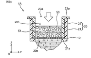
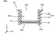
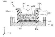
- 9A to 9E show an example of the steps of the filtration and recovery method according to the first embodiment of the present invention.
- the filtration and recovery method means a method of filtering a liquid containing an object to be filtered and collecting the object to be filtered using the filtration and recovery apparatus 1A.
- the filtration target 10 is captured by the filtration filter 10 by filtering the liquid 50 including the filtration target 51 using the filtration and recovery apparatus 1A.
- the filtration and recovery device 1A is attached to the centrifuge tube 40 (see FIG. 7), and the liquid 50 including the object to be filtered 51 is transferred from the inlet 20a of the holder 20 of the filtration and recovery device 1A to the flow path 20c inside the holder 20.
- FIG. 9A the illustration of the centrifuge tube 40 is omitted.
- the liquid 50 including the filtration target 51 passes through the filtration filter 10 arranged in the flow path 20c, and is discharged from the discharge port 20b. Thereby, as shown in FIG. 9B, the filtration target 51 larger than the through-hole 13 is captured on the first main surface PS1 of the filtration filter 10.
- step ST12 the filtration target 51 captured by the filtration and recovery apparatus 1A is washed. Specifically, a cleaning liquid is introduced into the filtration filter 10 to wash the object 51 to be filtered.
- the outlet 20b of the holder 20 of the filtration and recovery device 1A is closed.
- the filtration and recovery device 1A is arranged in a petri dish 60.
- one end of the holder 20 of the filtration and recovery device 1A where the discharge port 20b is provided is disposed on the bottom portion 61 of the petri dish 60. Since the bottom portion 61 of the petri dish 60 is formed in a flat shape, the bottom portion 61 comes into surface contact with the end face on one end side of the holder 20 provided with the discharge port 20b. In addition, the end face on one end side of the holder 20 provided with the discharge port 20b is formed in a flat shape as described above. As a result, the outlet 20b is closed by the bottom portion 61 of the petri dish 60. That is, the discharge port 20b is sealed by the bottom portion 61 of the petri dish 60.
- a collection liquid 52 (hereinafter, referred to as “liquid 52”) is introduced into the filtration and collection apparatus 1A. As shown in FIG. 9D, the liquid 52 is introduced from the inlet 20a of the holder 20. Since the outlet 20b of the holder 20 is closed by step ST13, the liquid 52 is held in the flow path 20c inside the holder 20.
- the filtration object 51 separates from the filtration filter 10 and floats in the liquid 52 held inside the holder 20.
- the state in which the discharge port 20b of the holder 20 is closed is a state in which the leakage of the liquid 52 is suppressed, and does not need to be a state in which the liquid 52 does not completely leak. It suffices if the flow path 20c inside the holder 20 can hold the liquid 52 of a liquid amount enough to recover the object 51 to be filtered. That is, in the filtration and recovery device 1A, in a state where the outlet 20b of the holder 20 is closed, leakage of the liquid 52 to such an extent that the recovery is not affected may be allowed.
- step ST15 the filtration target 51 is collected together with the liquid 52 held in the filtration and collection device 1A.
- the liquid 52 held in the flow path 20 c of the holder 20 is collected together with the filtration target 51 using a pipette 53.
- the filtration target 51 can be recovered together with the recovery liquid 52 by performing steps ST11 to ST15.
- the filtration and recovery apparatus 1A includes the filtration filter 10, and the holder 20 having the inlet 20a, the outlet 20b, and the flow path 20c communicating the inlet 20a and the outlet 20b.
- the filtration filter 10 is disposed above the outlet 20b in the flow path 20c of the holder 20.
- the filtration target 51 captured by the filtration filter 10 can be easily collected.
- the outlet 20b can be closed when the object to be filtered 51 is collected.
- the liquid 52 for collection can be introduced from the introduction port 20a of the holder 20, and the liquid 52 can be held in the flow path 20c inside the holder 20.
- the object to be filtered 51 can be easily collected together with the liquid 52 by the pipette 53.
- the outlet 20b can be easily closed.
- the outlet 20b can be closed without being affected by the filtration filter 10.
- the cell suspension when the object to be filtered is a cell, the cell suspension can be easily generated by using a solvent or the like as the liquid for recovery 52 and recovering the solvent together with the cells. In addition, by introducing the liquid for recovery, it is possible to prevent the captured cells from drying and maintain the activity. Further, by adjusting the amount of the collection liquid 52 to be introduced into the inside of the filtration and collection device 1A, the amount of the cell suspension to be generated can be easily adjusted. Further, the concentration of the cell suspension to be collected can be easily adjusted by adjusting the amount of the liquid for collection 52 to be introduced into the inside of the filtration and collection device 1A.
- a projection 21a projecting toward the inside of the holder 20 is formed, and the projection 21a holds the filtration filter 10.
- the filtration filter 10 can be disposed in the flow path 20c between the inlet 20a and the outlet 20b of the holder 20.
- the projection 21a is formed at one end of the holder 20 provided with the outlet 20b, and the filter 10 is disposed closer to the outlet 20b than the inlet 20a.
- the holder 20 has a cylindrical first holder 21 having a protrusion 21a and a cylindrical second holder 22 disposed inside the first holder 21.
- the filtration filter 10 is sandwiched between the protrusion 21 a of the first holder 21 and one end of the second holder 22. With such a configuration, the filtration filter 10 can be firmly fixed to the flow path 20c of the holder 20.
- One end of the holder 20 provided with the discharge port 20b is configured to make surface contact with the flat surface. With such a configuration, when one end of the holder 20 provided with the outlet 20b is placed on a flat surface, the outlet 20b can be easily closed.
- the filtration filter 10 includes a filter portion 11 having at least one of a metal and a metal oxide as a main component and having a plurality of through holes 13, and a frame portion 12 arranged so as to surround the outer periphery of the filter portion 11.
- a filter portion 11 having at least one of a metal and a metal oxide as a main component and having a plurality of through holes 13, and a frame portion 12 arranged so as to surround the outer periphery of the filter portion 11.
- the filtration object 51 can be easily collected, and the collection rate can be improved.
- the size and arrangement of the through-holes vary, and an object to be filtered may enter the through-holes.
- the size and arrangement of the through holes are designed to be more uniform than that of the resin filter.
- the filtration target 51 when the filtration target 51 is collected by using the filtration filter 10 containing at least one of a metal and a metal oxide, the filtration target 51 is removed from the filtration filter 10. It is easy to peel off, and the recovery rate can be improved as compared with the resin filter.
- the filtration filter 10 is a metal filter, but the present invention is not limited to this.
- the filtration filter 10 may be a film-like or sheet-like substance capable of filtering an object contained in the liquid 50.
- the filtration and recovery apparatus 1A may include a plurality of filtration filters.
- the plurality of filtration filters may be arranged in series in the direction in which the liquid 50 flows. Further, the dimensions of the through holes of the plurality of filtration filters may be different.
- the plurality of filtration filters may be arranged in series from the upstream side where the liquid 50 flows, in the order of the size of the through-hole. With such a configuration, it is possible to filter and collect filtration objects having different sizes at once.
- the filtering target 51 is a cell
- the liquid 50 is a cell suspension.
- the present invention is not limited to this.
- the holder 20 includes the first holder 21 and the second holder 22, but the present invention is not limited to this.
- the holder 20 may have the first holder 21 and the second holder 22 integrally formed, or may be configured by two or more parts.
- the frame portion 12 of the filtration filter 10 is sandwiched by the protrusion 21a of the first holder 21 and one end of the second holder 22 over the entire circumference, but is not limited thereto.
- the frame 12 may be partially held between the protrusion 21 a of the first holder 21 and one end of the second holder 22.
- the second holder 22 includes the flange 22a and the handle 22b, but the present invention is not limited to this.
- the flange 22a and the handle 22b are not essential components.
- a flange extending toward the outside of the holder 20 may be provided at one end of the holder 20 provided with the discharge port 20b.
- the filtration and recovery apparatus 1A is attached to the centrifuge tube 40 when performing filtration.
- the present invention is not limited to this.
- the filtration and recovery device 1A may be attached to a container or device other than the centrifuge tube.
- the discharge port 20b of the holder 20 is closed by the bottom portion 61 of the petri dish 60 at the time of collection.
- the present invention is not limited to this.
- the collection it is sufficient that the collection liquid 52 can be prevented from leaking from the discharge port 20b of the holder 20, and any configuration that closes the discharge port 20b may be used.
- the outlet 20b may be closed by a flat surface of a pedestal or the like.
- the outlet 20b may be closed by a smooth convex surface as well as a flat surface.
- step ST12 is not an essential component.
- the example of the filtration and collection method including the step ST13 of closing the discharge port 20b of the holder 20 and the step ST14 of introducing the collection liquid 52 into the holder 20 has been described, but the present invention is not limited thereto.
- the liquid 52 may be introduced into the holder 20 from the discharge port 20b by disposing the filtration and recovery device 1A in the petri dish 60 that stores the recovery liquid 52. More specifically, the filtration and recovery apparatus 1A is submerged in the liquid 52 with the one end of the holder 20 provided with the discharge port 20b facing the recovery liquid 52 stored in the petri dish 60. As a result, the liquid 52 enters the inside of the holder 20 from the outlet 20b. When one end of the holder 20 provided with the discharge port 20b is in surface contact with the bottom portion 61 of the petri dish 60, the discharge port 20b is closed, and the liquid 52 is held inside the holder 20.
- the filtration object 51 can be easily collected.
- the filtration and recovery method may recover the liquid 50 and the target that have passed through the filtration filter 10 of the filtration and recovery device 1A.
- the filtration and recovery device 1 ⁇ / b> A is attached to a container such as the centrifuge tube 40, the liquid 50 and the target that have passed through the filtration filter 10 accumulate at the bottom of the centrifuge tube 40.
- the filtration and recovery device 1A may be detached from the centrifuge tube 40 to collect the liquid 50 and the target collected inside the centrifuge tube 40.
- the filtration filter 10 is disposed substantially perpendicular to the inner wall of the holder 20 .
- the present invention is not limited to this.
- the filtration filter 10 may be arranged obliquely with respect to the inner wall of the holder 20.
- the filtration and recovery apparatus 1A and the filtration and recovery method have been described, but the present invention is not limited thereto.
- it may be used as a kit for performing a filtration method including the filtration and recovery device 1A.
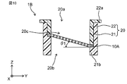
- FIG. 10 is a schematic configuration diagram of a filtration and recovery device 1B according to a modification of the first embodiment of the present invention.
- the filtration filter 10A may be arranged obliquely with respect to the inner wall of the holder 20. Specifically, by changing the height of the protrusion 21b of the first holder 21 along the inner wall of the holder 20, the filtration filter 10A is arranged obliquely with respect to the inner wall of the holder 20.
- the filter 10A can be disposed at an angle ⁇ 1 with respect to the inner wall of the holder 20.
- the inclination angle ⁇ 1 of the filtration filter 10A is set, for example, to 10 ° or more and 80 ° or less.
- the filtration target 51 can be easily collected, and thus can be more easily collected.
- the second embodiment is different from the first embodiment in that a liquid amount indicating section is provided on the inner wall of the holder.
- FIG. 11 is a schematic configuration diagram of an example of a filtration and recovery device 1C according to Embodiment 2 of the present invention.
- a liquid amount indicating unit 23 indicating the liquid amount of the liquid 52 held inside the holder 20 with the discharge port 20b closed is provided on the inner wall of the holder 20. Have been.
- the liquid amount indicating section 23 functions as a scale indicating the liquid amount of the liquid for recovery 52 held in the flow path 20c inside the holder 20.
- the user can collect the liquid 52 for collection with the filtration and collection device 1C based on the liquid volume instruction unit 23.
- the liquid 52 is introduced into the holder 20 until the liquid level of the liquid 52 held inside the holder 20 reaches the liquid amount indicating section 23 indicating a desired liquid amount.
- a desired amount of cell suspension can be generated during collection.
- the liquid amount indicating section 23 is formed by a plurality of grooves 23a.
- the plurality of grooves 23 a are provided in a ring shape on the inner wall of the holder 20.
- the plurality of grooves 23a are provided in order in the height direction of the filtration and recovery device 1C.
- a liquid amount indicating unit 23 indicating the liquid amount of the liquid 52 held inside the holder 20 with the discharge port 20b closed is provided on the inner wall of the holder 20.
- the liquid 52 required to generate a cell suspension having a desired liquid volume can be easily adjusted based on the liquid volume indicator 23.
- the concentration of the cell suspension can be adjusted by adjusting the liquid amount of the liquid 52 based on the liquid amount indicating section 23.
- a concentration adjusting step or a re-dispersion step for adjusting the cell suspension to a desired concentration can be omitted.
- liquid amount indicating portion 23 is formed by the plurality of grooves 23a
- present invention is not limited to this.
- the liquid amount indicating section 23 may have one or a plurality of grooves 23a.
- the liquid amount indicating section 23 may be any as long as it functions as a scale for confirming the liquid amount of the liquid 52 held in the holder 20.
- the liquid amount indicating unit 23 may be one or more concave portions, one or more convex portions, one or more characters, or a combination thereof.
- the filtration and recovery method may be performed using the filtration and recovery device 1C.
- step ST14 of the filtration and recovery method according to the first embodiment may include introducing the recovery liquid 52 based on the liquid amount instruction unit 23. With such a configuration, the amount of the liquid 52 to be collected together with the filtration target 51 can be adjusted.
- the third embodiment is different from the first and second embodiments in that a petri dish is provided.
- FIG. 12 is a schematic perspective view of an example of a filtration and recovery device 1D according to Embodiment 3 of the present invention.
- FIG. 13 is a schematic exploded perspective view of an example of a filtration and recovery device 1D according to Embodiment 3 of the present invention.
- FIG. 14 is a schematic cross-sectional view of an example of a filtration and recovery device 1D according to Embodiment 3 of the present invention.
- the filtration and recovery apparatus 1D includes a petri dish 30 detachably attached to the holder 20.
- the petri dish 30 is removed from the holder 20 when performing filtration, and attached to the holder 20 when performing collection.
- the petri dish 30 is formed in a size that can accommodate one end of the holder 20 provided with the discharge port 20b.
- the Petri dish 30 has a bottom portion 31 and a side wall portion 32 formed along the outer edge of the bottom portion 31 and extending upward from the bottom portion 31.
- the petri dish 30 is detachably attached to one end of the holder 20 provided with the discharge port 20b.
- the bottom surface portion 31 is disposed at one end of the holder 20 provided with the discharge port 20b.
- the side wall portion 32 is arranged so as to surround the outer wall of the holder 20.
- the discharge port 20b is closed by the contact between the bottom surface 31 and one end of the holder 20. Further, by reducing or eliminating the space between the side wall portion 32 and the outer wall of the holder 20, the space where the liquid 52 held inside the holder 20 leaks from the discharge port 20b is reduced or eliminated. ing.
- the bottom 31 of the petri dish 30 is formed flat.
- the side wall 32 of the petri dish 30 is arranged along the outer wall of the holder 20 and is in surface contact with the outer wall of the holder 20.
- the inner wall of the side wall portion 32 of the petri dish 30 is in surface contact with the outer wall of the holder 20. Specifically, the inner wall of the side wall portion 32 of the petri dish 30 is in surface contact with the outer wall of the first holder 21. Thereby, the contact area between the petri dish 30 and the holder 20 can be increased, and the sealing performance of the filtration and recovery device 1D can be improved. That is, leakage of the liquid 52 held inside the holder 20 to the outside of the holder 20 can be suppressed.
- the petri dish 30 has a bottom portion 31 and a side wall portion 32 formed along the outer edge of the bottom portion 31 and extending upward from the bottom portion 31.
- the petri dish 30 is provided with a discharge port 20b. Is detachably attached to one end of the holder 20. With such a configuration, it is possible to further suppress the leakage of the liquid 52 from the outlet 20b when the filtration target 51 is collected. Therefore, the filtration target 51 can be more easily collected.
- the present invention is not limited to this.
- the side wall 32 of the petri dish 30 may not be in surface contact with the outer wall of the holder 20. It suffices if the space between the side wall portion 32 of the petri dish 30 and the outer wall of the holder 20 is reduced, so that the leakage of the liquid 52 from the discharge port 20b can be suppressed.
- FIG. 15 is a schematic configuration diagram of a filtration and recovery apparatus 1E according to a modification of the third embodiment of the present invention.
- the filtration and recovery device 1 ⁇ / b> E may be provided with a liquid amount indicating section 23 on the inner wall of the holder 20.
- the user can easily confirm the amount of the liquid 52 held in the holder 20. This makes it possible to easily adjust the amount of the liquid 52 required for recovery.
- the fourth embodiment will mainly describe points different from the first embodiment.
- the same or equivalent components as those in the first embodiment are denoted by the same reference numerals and described.
- descriptions overlapping with the first embodiment are omitted.
- the fourth embodiment is different from the first embodiment in that the filtration filter is removed from the filtration and recovery device, and the filtration target is recovered by immersing the filtration filter in the recovery liquid.
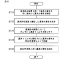
- FIG. 16 is a flowchart of an example of the filtration and recovery method according to the fourth embodiment of the present invention.
- the filtration target 10 is captured by the filtration filter 10 by filtering the liquid 50 including the filtration target 51 using the filtration and recovery apparatus 1A.
- the filtration and recovery device 1A is attached to the centrifuge tube 40 (see FIG. 7), and the liquid 50 including the object to be filtered 51 is transferred from the inlet 20a of the holder 20 of the filtration and recovery device 1A to the flow path 20c inside the holder 20. Introduce.
- step ST22 the filtration target 51 captured by the filtration and recovery apparatus 1A is washed. Specifically, a cleaning liquid is introduced into the filtration filter 10 to wash the object 51 to be filtered.
- step ST23 the filtration filter 10 is removed from the holder 20 in the filtration and recovery apparatus 1A. Specifically, after removing the filtration and recovery device 1A from the centrifuge tube 40, the second holder 22 is removed from the first holder 21. Then, the filter 10 is removed from the first holder 21. In addition, in step ST23, the filtration filter 10 is removed from the holder 20 while the filtration target 51 is captured on the first main surface PS1 of the filtration filter 10.
- step ST24 the filtration target 51 captured by the filtration filter 10 is peeled off by the recovery liquid. Specifically, the filtration filter 10 is immersed in a container storing the liquid for recovery. As a result, the object to be filtered is separated from the first main surface PS1 of the filter 10. Alternatively, the object to be filtered is easily separated from the filter 10.
- step ST25 the filtration target 51 is collected together with the liquid in which the filtration filter 10 is immersed.
- the object to be filtered 51 is collected together with the liquid using a pipette.
- the filtration target 51 can be recovered together with the recovery liquid by performing steps ST21 to ST25.
- the filtration filter 10 is removed from the holder 20, and the filtration filter 10 is immersed in the recovery liquid. Accordingly, the filtration target 51 captured by the filtration filter 10 leaves the filtration filter 10, and thus the filtration target 51 can be easily collected.
- step ST24 the example in which the filtration filter 10 is immersed in the collection liquid has been described in step ST24, but the invention is not limited to this.
- the collection liquid may be poured on the filtration filter 10.
- step ST25 the collection target liquid 51 separated from the filtration filter 10 is collected together with the collection liquid by flowing the collection liquid to the filtration filter 10.
- step ST22 is not essential.
- the fifth embodiment is different from the first embodiment in that the cell aggregate is separated into cells.
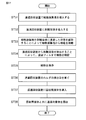
- FIG. 17 is a flowchart of an example of the filtration and recovery method according to the fifth embodiment of the present invention.
- the cell aggregate is introduced into the filtration and recovery device 1A. Specifically, the cell aggregate is arranged on the first main surface PS1 of the filtration filter 10 in the holder 20.
- the stripping solution is introduced into the filtration and recovery device 1A. Specifically, the stripping solution is introduced from the inlet 20a of the holder 20 with the outlet 20b of the holder 20 closed, and the cell aggregates disposed on the filter 10 are immersed in the stripping solution.
- a trypsin solution was used as the stripping solution.
- step ST33 the cells are detached from the cell aggregate by maintaining the state where the cell aggregate is immersed in the stripping solution. Specifically, the state where the cell aggregate is immersed in the stripping solution is maintained for a predetermined time.
- the predetermined time is, for example, 5 minutes.
- step ST34 cells are captured by the filtration filter 10 by discharging the stripping solution from the filtration and recovery device 1A. Specifically, the outlet 20b of the holder 20 of the filtration and recovery apparatus 1A is opened, and the stripping solution is discharged from the outlet 20b. Thereby, the cells are captured by the filtration filter 10.
- step ST35 the outlet 20b of the holder 20 of the filtration and recovery apparatus 1A is closed. Specifically, one end of the holder 20 provided with the discharge port 20b is arranged on a flat surface, and the one end of the holder 20 and the flat surface are brought into surface contact.
- a liquid for recovery is introduced into the filtration and recovery apparatus 1A. Specifically, the collection liquid is introduced from the introduction port 20a of the holder 20, and the collection liquid is held in the flow path 20c of the holder 20.
- step ST37 cells are collected together with the liquid for collection.
- the cells are collected together with the collection liquid held in the flow path 20c of the holder 20.
- the cells detached from the cell aggregate can be recovered together with the recovery liquid.
- the cells can be detached from the cell aggregates, and the detached cells can be easily collected together with the liquid for collection.
- the filtration and recovery method according to Embodiment 5 can be used as a method for detaching cells from cell aggregates.
- the time during which the cells are in contact with the stripping solution for example, trypsin solution
- the stripping solution for example, trypsin solution
- the possibility of reaggregation of the detached cells is small, and physical damage to the cells can be reduced.
- step ST32 introduces the stripping solution from the inlet 20a of the holder 20 has been described, but the present invention is not limited to this.
- the filtration and recovery device 1A may be immersed in a container holding the stripping solution.
- step 35 is not an essential component.
- the sixth embodiment is different from the first embodiment in that the solvent is introduced into the filtration and recovery device before the liquid containing the filtration target is introduced into the filtration and collection device.
- FIG. 18 is a flowchart of an example of the filtration and recovery method according to the sixth embodiment of the present invention.
- a solvent is introduced into the filtration and recovery device 1A. Specifically, the solvent is introduced from the inlet 20a of the holder 20 while the outlet 20b of the holder 20 is closed.
- the solvent is the same as the liquid 50 including the filtration target 51.
- step ST42 the filtration target 10 is captured by the filtration filter 10 by introducing the liquid 50 containing the filtration target 51 into the filtration and recovery apparatus 1A. Specifically, the discharge port 20b of the holder 20 is opened, and the liquid 50 including the filtration object 51 is introduced from the introduction port 20a of the holder 20.
- step ST43 the filtration target 51 captured by the filtration and recovery apparatus 1A is washed. Specifically, a cleaning liquid is introduced into the filtration filter 10 to wash the object 51 to be filtered.
- step ST44 the discharge port 20b of the holder 20 of the filtration and recovery device 1A is closed.
- a collection liquid is introduced into the filtration and collection device 1A. Specifically, the collection liquid is introduced from the introduction port 20a of the holder 20. Since the outlet 20b of the holder 20 is closed by step ST44, the liquid 52 is held in the flow path 20c inside the holder 20.
- the filtration object 51 separates from the filtration filter 10 and floats in the recovery liquid held inside the holder 20.
- step ST46 the filtration target 51 is collected together with the collection liquid held in the filtration and collection device 1A.
- the filtration object 51 can be recovered together with the recovery liquid by performing steps ST41 to ST46.
- the solvent is introduced into the filtration and recovery device 1A before the liquid 50 containing the filtration target 51 is introduced into the filtration and recovery device 1A.
- step ST41 the example in which the solvent is introduced from the inlet 20a of the holder 20 while the outlet 20b of the holder 20 is closed has been described in step ST41, but the present invention is not limited to this.
- the solvent may be introduced into the filtration and collection device 1A by immersing the filtration and collection device 1A in a container holding the solvent.
- step ST43 is not an essential component.
- Example 1 will be described. As Example 1, the filtration and recovery of the cell suspension were performed using the filtration and recovery apparatus 1A of Embodiment 1, and the recovered cell suspension was evaluated. In addition, evaluation was performed using Comparative Example 1-3 under the same conditions as in Example 1.
- Table 1 shows the information of the filtration and recovery device 1A used in Example 1. Note that the configuration of the filtration and recovery device 1A of Example 1 has been described in Embodiment 1, and thus the description thereof is omitted. Further, the interval between the through holes shown in Table 1 means the width dimension of the filter base 14 that divides the two adjacent through holes 13.
- the “outer diameter of the holder 20” corresponds to the outer diameter of the first holder 21.
- Inner diameter of holder 20 corresponds to the inner diameter of second holder 22.
- Height of holder 20 corresponds to the length of holder 20 in the Z direction.
- the height of the protrusion 21a means the length of the protrusion 21a in the Z direction.
- FIG. 19 is a schematic configuration diagram of the filtration and recovery device 101A of Comparative Example 1.
- a filtration filter 110A is disposed at an outlet 121b of a holder 120A.
- the swell of the filtration filter 110A prevents the discharge port 121b from being blocked.
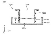
- FIG. 20 is a schematic configuration diagram of a filtration and recovery apparatus 101B of Comparative Example 2.
- the filtration filter 110B is disposed above the outlet 122b of the holder 120B.
- Filtration filter 110B forms a part of the side wall of holder 120B.
- the collection liquid 52 is introduced from the introduction port 122a
- the liquid 52 leaks from a part of the filtration filter 110B which forms a part of the side wall of the holder 120B. Therefore, the liquid cannot be held inside the holder 120B, and a certain amount of liquid cannot be collected. Further, the time that the cells to be filtered contact the atmosphere or the filter 110B is prolonged, and the cells are damaged. This may reduce the activity of the cells.
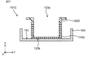
- FIG. 21 is a schematic configuration diagram of a filtration and recovery apparatus 101C of Comparative Example 3.
- a resin filter is used as the filtration filter 110B.
- the filtration filter 110B is disposed at the outlet 122b of the holder 120C. Further, the filtration filter 110C forms a part of the side wall of the holder 120C.
- the collection liquid 52 is introduced from the introduction port 123a, the liquid 52 leaks from a part of the filter 110C that forms a part of the side wall of the holder 120C.
- the filtration filters 110A and 110B are designed to have the same dimensions as the filtration filter 10 of the first embodiment.
- a resin filter is used as the filtration filter 110C, but a resin filter corresponding to the dimensions of the filtration filter 10 of Example 1 is used for the outer diameter, thickness, and size of the through hole of the filter.
- the holders 120A, 120B, and 120C are designed to have the same dimensions as the holder 20 of Example 1 except for the height of the protrusion. Note that Comparative Examples 1 and 3 did not have a projection, and Comparative Example 2 had a projection height of 4.1 mm.
- Example 1 and Comparative Example 1-3 the filtration / recovery devices 1A, 101A, 101B, and 101C were respectively attached to the upper portions of 50 mL centrifuge tubes, and the cell suspension was introduced from the inlets 20a, 121a, 122a, and 123a. The cell suspension was filtered. Table 2 shows the conditions of the filtration performed in Example 1 and Comparative Example 1-3.
- Example 1 after 20 seconds from the start of filtration using the filtration and recovery apparatus 1A, the cell suspension disappears on the first main surface PS1 of the filtration filter 10, and the cells on the first main surface PS1 are captured. It was visually confirmed that the film was clouded. The state where the cell suspension disappeared on the first main surface PS1 of the filtration filter 10 and the cells were captured on the first main surface PS1 was visually confirmed. Immediately after the confirmation, 5 mL of PBS (Phosphate Buffered Saline) was introduced from the inlet 20a of the holder 20, and the cells captured on the filter 10 were washed.
- PBS Phosphate Buffered Saline
- Comparative Example 1-3 filtration was performed using the filtration filters 110A, 110B, and 110C, respectively, and the state in which cells were captured by the filtration filters 110A, 110B, and 110C was visually confirmed.
- Comparative Example 3 since a resin filter was used for the filtration filter 110C, filtration was performed by suction at a pressure of 30 kPa. Also in Comparative Example 1-3, the cells captured by the filtration filters 110A, 110B, and 110C were washed with PBS.
- Example 1 After the washing, in Example 1, the filtration and recovery apparatus 1A was disposed on the bottom portion 61 of a petri dish 60 having an outer diameter of 35 mm, and 5 mL of PBS was introduced as the recovery liquid 52 from the inlet 20a of the holder 20. Next, the target suspension volume of the cell suspension was set to 3 mL, and the cell suspension held inside the holder 20 by the pipette 53 was manually recovered. Similarly, in Comparative Example 1-3, the filtration / recovery devices 101A, 101B, and 101C were respectively disposed on the bottom surface 161 of the petri dish 160, and 5 mL of PBS was introduced into each of the holders 120A, 120B, and 120C. Next, the target suspension volume of the cell suspension was set to 3 mL, and the cell suspensions held inside 120A, 120B, and 120C were manually collected by the pipette 53, respectively.
- Example 1 With respect to the cell suspension collected in Example 1 and Comparative Example 1-3, the amount of the collected liquid, the number of cells in the collected cell suspension, the cell recovery rate, and the cell viability were evaluated.
- the amount of the recovered liquid was measured using a measuring cylinder.
- the cells stained with trypan blue were counted using an automatic cell counter (CountsIIFL manufactured by Invitrogen), and the total number of cells, the number of living cells, and the number of dead cells in 1 mL were measured.
- Cell recovery rate [%] (number of cells in suspension after filtration [cells]) / (number of cells in suspension before filtration [cells]) ⁇ 100
- Cell viability [%] (viable cell count [cells]) / (total cell count [cells]) ⁇ 100
- Table 3 shows the evaluation results.
- Example 1 the cell recovery rate was 96% and the cell survival rate was 98%.
- the liquid amount of the cell suspension collected using the pipette 53 was 2.97 mL with respect to the target collected liquid amount of 3 mL. That is, the recovery rate of the cell suspension with respect to the target recovery liquid volume was 99%.
- Example 1 the cell recovery rate was as high as 96%, which indicates that the cells captured by the filtration filter 10 could be easily recovered.
- the survival rate of the cells was 98%, indicating that the cells could be collected without damaging the cells.
- the amount of the recovered cell suspension was 99% of the target amount of the recovered liquid, indicating that a desired amount of the cell suspension could be recovered.
- the cell recovery rate was 52% and the cell survival rate was 96%.
- the amount of the recovered cell suspension was 1.56 mL, and the recovery rate of the cell suspension with respect to the target amount of the recovered liquid was 52%.
- Comparative Example 1 the amount of the recovered cell suspension is smaller than in Example 1.
- the filter filter 110A is disposed at the outlet 122b of the holder 120A, and the filter filter 110A itself has undulation. It is considered that the cell suspension leaked from 121b.
- Comparative Example 2 the cell recovery rate was 30% and the cell survival rate was 90%. In Comparative Example 2, the amount of the recovered cell suspension was 0.30 mL, and the recovery rate of the cell suspension with respect to the target amount of the recovered liquid was 10%.
- Comparative Example 2 has a lower cell recovery rate and a smaller cell suspension liquid volume than Example 1.
- a part of the side wall of the holder 120B is formed by the filtration filter 110B.
- the cell suspension held inside the holder 120B leaks from the part of the filter 110B that forms a part of the side surface of the holder 120B. It is considered that this reduced the amount of the recovered cell suspension.
- Comparative Example 3 the cell recovery rate was 31% and the cell survival rate was 89%. In Comparative Example 3, the amount of the recovered cell suspension was 0.28 mL, and the recovery rate of the cell suspension with respect to the target amount of the recovered liquid was 9%.
- Comparative Example 3 has a lower cell recovery rate and cell viability than Example 1, and also has a smaller liquid volume of the recovered cell suspension.
- the filtration filter 110B is arranged at the outlet 122b of the holder 120C. Further, the filter 110C forms a part of the side wall of the holder 120C. Therefore, in Comparative Example 3, the cell suspension in the holder 120C leaks from the filter filter 110C that forms a part of the side wall of the holder 120C. Therefore, it is considered that the amount of the recovered cell suspension was reduced. In addition, it is considered that, since it is difficult to hold the liquid inside the holder 120B, the cells are less likely to separate from the filtration filter 110B, and the cell recovery rate is reduced.
- a resin filter is used as the filtration filter 110C.
- the liquid does not pass through the filtration filter 110C, so that the inside of the centrifuge tube is in a negative pressure state.
- cells enter the through-holes of the filtration filter 110C and cannot be collected, so that pipetting is required.
- deformation and damage to the cells were confirmed. It is considered that the cells were deformed or damaged due to the effects of filtration and pipetting in a negative pressure state, and cell viability was reduced.
- Example 2 the cell suspension was filtered and collected using the filtration and recovery apparatus 1A of Embodiment 1, and the collected cell suspension was evaluated.
- Example 2 since an experiment was performed with a smaller amount of liquid than in Example 1, an apparatus smaller in size than the filtration and recovery apparatus 1A of Example 1 was used.
- Table 4 shows the information of the filtration and recovery device 1A used in Example 2. Note that the configuration of the filtration and recovery apparatus 1A according to the second embodiment has been described in the first embodiment, and a description thereof will be omitted. Further, the interval between the through holes 13 shown in Table 4 means the width dimension of the filter base 14 that divides the two adjacent through holes 13.
- Example 2 the filtration and recovery apparatus 1A was attached to the upper part of a 15 ml centrifuge tube, the cell suspension was introduced from the inlet 20a, and the cell suspension was filtered.
- Table 5 shows the conditions of the filtration performed in Example 2.
- Example 2 60 seconds after the start of the filtration using the filtration and recovery apparatus 1A, the cell suspension disappears on the first main surface PS1 of the filtration filter 10, and the cells are captured on the first main surface PS1. The state in which it was present was visually checked. Immediately after the confirmation, 5 mL of PBS (Phosphate Buffered Saline) was introduced from the inlet 20a of the holder 20, and the cells captured on the filter 10 were washed.
- PBS Phosphate Buffered Saline
- the filtration and recovery apparatus 1A was placed on the bottom surface 61 of a petri dish 60 having an outer diameter of 35 mm, and 5 mL of PBS was introduced as the recovery liquid 52 from the inlet 20a of the holder 20.
- the target suspension volume of the cell suspension was set to 0.5 mL, and the cell suspension held inside the holder 20 by the pipette 53 was manually recovered.
- the recovery rate of the cells was 98%, and the survival rate of the cells was 98%.
- the liquid amount of the cell suspension manually collected using the pipette 53 was 0.48 mL with respect to the target collected liquid amount of 0.5 mL. That is, the recovery rate of the cell suspension with respect to the target recovery liquid amount was 96%.
- the filtration and recovery apparatus of the present invention is useful for recovering a biological substance in a fluid at a high recovery rate, and is effectively applied to the regenerative medicine industry, food industry, and the like.
Landscapes
- Chemical & Material Sciences (AREA)
- Life Sciences & Earth Sciences (AREA)
- Engineering & Computer Science (AREA)
- Bioinformatics & Cheminformatics (AREA)
- Health & Medical Sciences (AREA)
- Chemical Kinetics & Catalysis (AREA)
- Zoology (AREA)
- Biotechnology (AREA)
- Organic Chemistry (AREA)
- Wood Science & Technology (AREA)
- Geology (AREA)
- Biochemistry (AREA)
- Biomedical Technology (AREA)
- General Engineering & Computer Science (AREA)
- General Health & Medical Sciences (AREA)
- Genetics & Genomics (AREA)
- Microbiology (AREA)
- Medicinal Chemistry (AREA)
- Sustainable Development (AREA)
- Inorganic Chemistry (AREA)
- Ceramic Engineering (AREA)
- Apparatus Associated With Microorganisms And Enzymes (AREA)
- Micro-Organisms Or Cultivation Processes Thereof (AREA)
- Separation Of Solids By Using Liquids Or Pneumatic Power (AREA)
- Filtration Of Liquid (AREA)
- Aiming, Guidance, Guns With A Light Source, Armor, Camouflage, And Targets (AREA)
Abstract
La présente invention aborde le problème consistant à récupérer facilement un objet à filtrer. Le dispositif de récupération par filtration selon la présente invention comprend : un filtre de filtration ayant une pluralité de trous traversants ; et un support ayant une ouverture d'entrée pour l'entrée d'un liquide, une ouverture d'évacuation pour l'évacuation du liquide, et un passage pour relier entre elles l'ouverture d'entrée et l'ouverture d'évacuation. Le filtre de filtration est positionné sur le passage du support entre l'ouverture d'entrée et l'ouverture d'évacuation. Une telle configuration permet de récupérer facilement un objet à filtrer.
Priority Applications (5)
| Application Number | Priority Date | Filing Date | Title |
|---|---|---|---|
| JP2020529005A JP7001160B2 (ja) | 2018-07-03 | 2019-07-02 | 濾過回収装置及び濾過回収方法 |
| CN201980044621.0A CN112469810B (zh) | 2018-07-03 | 2019-07-02 | 过滤回收装置以及过滤回收方法 |
| US17/095,419 US12030002B2 (en) | 2018-07-03 | 2020-11-11 | Filtration recovery device and filtration recovery method |
| JP2021203825A JP7248093B2 (ja) | 2018-07-03 | 2021-12-16 | 濾過回収装置及び濾過回収方法 |
| US18/676,015 US12528033B2 (en) | 2018-07-03 | 2024-05-28 | Filtration recovery device and filtration recovery method |
Applications Claiming Priority (2)
| Application Number | Priority Date | Filing Date | Title |
|---|---|---|---|
| JP2018-126593 | 2018-07-03 | ||
| JP2018126593 | 2018-07-03 |
Related Child Applications (1)
| Application Number | Title | Priority Date | Filing Date |
|---|---|---|---|
| US17/095,419 Continuation US12030002B2 (en) | 2018-07-03 | 2020-11-11 | Filtration recovery device and filtration recovery method |
Publications (1)
| Publication Number | Publication Date |
|---|---|
| WO2020009099A1 true WO2020009099A1 (fr) | 2020-01-09 |
Family
ID=69060413
Family Applications (1)
| Application Number | Title | Priority Date | Filing Date |
|---|---|---|---|
| PCT/JP2019/026251 Ceased WO2020009099A1 (fr) | 2018-07-03 | 2019-07-02 | Dispositif de récupération par filtration et procédé de récupération par filtration |
Country Status (4)
| Country | Link |
|---|---|
| US (2) | US12030002B2 (fr) |
| JP (2) | JP7001160B2 (fr) |
| CN (1) | CN112469810B (fr) |
| WO (1) | WO2020009099A1 (fr) |
Cited By (2)
| Publication number | Priority date | Publication date | Assignee | Title |
|---|---|---|---|---|
| WO2021241283A1 (fr) * | 2020-05-25 | 2021-12-02 | 東京応化工業株式会社 | Procédé et système de séparation des particules cibles |
| JP2022106580A (ja) * | 2021-01-07 | 2022-07-20 | 横河電機株式会社 | 容器、培養キット、核酸分析システム |
Families Citing this family (6)
| Publication number | Priority date | Publication date | Assignee | Title |
|---|---|---|---|---|
| WO2020009099A1 (fr) * | 2018-07-03 | 2020-01-09 | 株式会社村田製作所 | Dispositif de récupération par filtration et procédé de récupération par filtration |
| CN115990365A (zh) * | 2018-08-23 | 2023-04-21 | 株式会社村田制作所 | 过滤装置以及过滤方法 |
| IT202000007180A1 (it) * | 2020-04-03 | 2021-10-03 | Tecniplast Spa | Dispositivo di screening microbiologico, in particolare per la raccolta e concentrazione di materiale organico e inorganico presente in un liquido, e apparecchiatura per l’allevamento di specie animali acquatiche da laboratorio equipaggiata con detto dispositivo |
| JP1708287S (ja) * | 2021-07-16 | 2022-02-25 | 細胞用濾過フィルタ | |
| USD1042844S1 (en) * | 2021-07-16 | 2024-09-17 | Murata Manufacturing Co., Ltd. | Cell filter |
| JP2024071298A (ja) * | 2022-11-14 | 2024-05-24 | 株式会社オプトニクス精密 | 細胞回収装置及び細胞回収方法 |
Citations (5)
| Publication number | Priority date | Publication date | Assignee | Title |
|---|---|---|---|---|
| JPS62221459A (ja) * | 1986-03-20 | 1987-09-29 | コスタ−・コ−ポレ−シヨン | 遠心管用フイルタ |
| JP2004317179A (ja) * | 2003-04-11 | 2004-11-11 | Shimadzu Corp | 精製用容器 |
| JP2011525805A (ja) * | 2008-06-27 | 2011-09-29 | ポステック アカデミー−インダストリー ファンデーション | 核酸抽出装置 |
| WO2017159367A1 (fr) * | 2016-03-18 | 2017-09-21 | 株式会社村田製作所 | Membrane poreuse métallique, et procédé de classification et dispositif de classification utilisant celle-ci |
| WO2018003104A1 (fr) * | 2016-06-30 | 2018-01-04 | 株式会社島津製作所 | Ensemble de récipients et procédé de préparation d'échantillon l'utilisant |
Family Cites Families (14)
| Publication number | Priority date | Publication date | Assignee | Title |
|---|---|---|---|---|
| EP0448837B1 (fr) * | 1990-03-02 | 1998-08-19 | Cytyc Corporation | Méthode et appareil pour l'instrumentation contrÔlée de particules au moyen d'un dispositif filtrant |
| US5308483A (en) * | 1992-08-27 | 1994-05-03 | Gelman Sciences Inc. | Microporous filtration funnel assembly |
| JP2000202023A (ja) * | 1999-01-19 | 2000-07-25 | Fuji Photo Film Co Ltd | 血液濾過器 |
| KR100634198B1 (ko) * | 2002-04-26 | 2006-10-16 | 니뽄 가이시 가부시키가이샤 | 필터 카트리지 |
| DK1656196T3 (da) * | 2003-08-25 | 2010-01-04 | Pall Corp | Filterindretning |
| US20060144781A1 (en) * | 2005-01-04 | 2006-07-06 | Global Water, Llc | Water purification system |
| US9290731B2 (en) * | 2008-12-19 | 2016-03-22 | Stemcell Technologies Inc. | Filter apparatus and filter plate system |
| US20110178424A1 (en) * | 2010-01-19 | 2011-07-21 | Becton, Dickinson And Company | Specimen Collection Container Having a Transitional Fill-Volume Indicator Indicating Extraction Method |
| JP2013141456A (ja) | 2012-01-13 | 2013-07-22 | Asahi Glass Co Ltd | セルストレーナー |
| EP3187578A4 (fr) | 2014-08-29 | 2018-05-02 | Hitachi Chemical Company, Ltd. | Procédé de piégeage de cellules, procédé pour produire un dispositif de piégeage de cellules spécifiques et procédé pour produire une solution contenant des cellules spécifiques |
| GB201515531D0 (en) * | 2015-09-02 | 2015-10-14 | Yip Lydia | Filtration device |
| CN108025238B (zh) * | 2016-08-30 | 2020-10-30 | 株式会社村田制作所 | 过滤滤除器、过滤装置以及使用过滤滤除器的过滤方法 |
| US10845275B2 (en) * | 2017-07-17 | 2020-11-24 | Hologic, Inc. | Fine tank pressure control using thermal energy for preparing cytological specimens from patient samples |
| WO2020009099A1 (fr) * | 2018-07-03 | 2020-01-09 | 株式会社村田製作所 | Dispositif de récupération par filtration et procédé de récupération par filtration |
-
2019
- 2019-07-02 WO PCT/JP2019/026251 patent/WO2020009099A1/fr not_active Ceased
- 2019-07-02 CN CN201980044621.0A patent/CN112469810B/zh active Active
- 2019-07-02 JP JP2020529005A patent/JP7001160B2/ja active Active
-
2020
- 2020-11-11 US US17/095,419 patent/US12030002B2/en active Active
-
2021
- 2021-12-16 JP JP2021203825A patent/JP7248093B2/ja active Active
-
2024
- 2024-05-28 US US18/676,015 patent/US12528033B2/en active Active
Patent Citations (5)
| Publication number | Priority date | Publication date | Assignee | Title |
|---|---|---|---|---|
| JPS62221459A (ja) * | 1986-03-20 | 1987-09-29 | コスタ−・コ−ポレ−シヨン | 遠心管用フイルタ |
| JP2004317179A (ja) * | 2003-04-11 | 2004-11-11 | Shimadzu Corp | 精製用容器 |
| JP2011525805A (ja) * | 2008-06-27 | 2011-09-29 | ポステック アカデミー−インダストリー ファンデーション | 核酸抽出装置 |
| WO2017159367A1 (fr) * | 2016-03-18 | 2017-09-21 | 株式会社村田製作所 | Membrane poreuse métallique, et procédé de classification et dispositif de classification utilisant celle-ci |
| WO2018003104A1 (fr) * | 2016-06-30 | 2018-01-04 | 株式会社島津製作所 | Ensemble de récipients et procédé de préparation d'échantillon l'utilisant |
Cited By (6)
| Publication number | Priority date | Publication date | Assignee | Title |
|---|---|---|---|---|
| WO2021241283A1 (fr) * | 2020-05-25 | 2021-12-02 | 東京応化工業株式会社 | Procédé et système de séparation des particules cibles |
| JPWO2021241283A1 (fr) * | 2020-05-25 | 2021-12-02 | ||
| JP7734659B2 (ja) | 2020-05-25 | 2025-09-05 | 東京応化工業株式会社 | ターゲット粒子の分離方法およびシステム |
| US12551886B2 (en) | 2020-05-25 | 2026-02-17 | Tokyo Ohka Kogyo Co., Ltd. | Target particle separation method and system |
| JP2022106580A (ja) * | 2021-01-07 | 2022-07-20 | 横河電機株式会社 | 容器、培養キット、核酸分析システム |
| JP7635554B2 (ja) | 2021-01-07 | 2025-02-26 | 横河電機株式会社 | 容器、培養キット、核酸分析システム、及び細胞培養方法 |
Also Published As
| Publication number | Publication date |
|---|---|
| US20240316480A1 (en) | 2024-09-26 |
| US20210060457A1 (en) | 2021-03-04 |
| CN112469810B (zh) | 2024-10-11 |
| US12030002B2 (en) | 2024-07-09 |
| US12528033B2 (en) | 2026-01-20 |
| JPWO2020009099A1 (ja) | 2021-04-30 |
| JP2022033176A (ja) | 2022-02-28 |
| CN112469810A (zh) | 2021-03-09 |
| JP7248093B2 (ja) | 2023-03-29 |
| JP7001160B2 (ja) | 2022-02-04 |
Similar Documents
| Publication | Publication Date | Title |
|---|---|---|
| WO2020009099A1 (fr) | Dispositif de récupération par filtration et procédé de récupération par filtration | |
| JP6665880B2 (ja) | 有核細胞の濾過用フィルターおよびそれを用いた濾過方法 | |
| JP6249124B1 (ja) | 有核細胞の濾過用フィルターおよびそれを用いた濾過方法 | |
| CN103298546B (zh) | 用于细胞过滤的方法和系统 | |
| JP5704590B2 (ja) | サイズ選択マイクロキャビティアレイを用いた循環腫瘍細胞の検出 | |
| US11389752B2 (en) | Filtration device | |
| JP2017159300A (ja) | 濾過装置 | |
| WO2017022484A1 (fr) | Dispositif de filtration à filtre | |
| WO2021049163A1 (fr) | Appareil et procédé de concentration | |
| JPWO2021049163A5 (fr) | ||
| JP2016180753A (ja) | 稀少細胞を分離又は検出する方法 | |
| JPWO2017104259A1 (ja) | 濾過フィルタ | |
| JP7294432B2 (ja) | 濾過回収装置 | |
| US20200346144A1 (en) | Filtration filter and filtration device | |
| JPWO2021054001A5 (fr) | ||
| JP4417120B2 (ja) | 標本作製装置 | |
| JP6815307B2 (ja) | 有核細胞の濾過用フィルターおよびそれを用いた濾過方法 | |
| JP2025013620A (ja) | 細胞回収装置及び細胞回収方法 |
Legal Events
| Date | Code | Title | Description |
|---|---|---|---|
| 121 | Ep: the epo has been informed by wipo that ep was designated in this application |
Ref document number: 19831007 Country of ref document: EP Kind code of ref document: A1 |
|
| ENP | Entry into the national phase |
Ref document number: 2020529005 Country of ref document: JP Kind code of ref document: A |
|
| NENP | Non-entry into the national phase |
Ref country code: DE |
|
| 122 | Ep: pct application non-entry in european phase |
Ref document number: 19831007 Country of ref document: EP Kind code of ref document: A1 |