WO2020009101A1 - Élément de liaison pour matériaux de construction, raccord de liaison associé, structure de liaison associée, et procédé de liaison associé - Google Patents
Élément de liaison pour matériaux de construction, raccord de liaison associé, structure de liaison associée, et procédé de liaison associé Download PDFInfo
- Publication number
- WO2020009101A1 WO2020009101A1 PCT/JP2019/026256 JP2019026256W WO2020009101A1 WO 2020009101 A1 WO2020009101 A1 WO 2020009101A1 JP 2019026256 W JP2019026256 W JP 2019026256W WO 2020009101 A1 WO2020009101 A1 WO 2020009101A1
- Authority
- WO
- WIPO (PCT)
- Prior art keywords
- connecting member
- building materials
- building material
- building
- locked
- Prior art date
- Legal status (The legal status is an assumption and is not a legal conclusion. Google has not performed a legal analysis and makes no representation as to the accuracy of the status listed.)
- Ceased
Links
Images













Classifications
-
- E—FIXED CONSTRUCTIONS
- E06—DOORS, WINDOWS, SHUTTERS, OR ROLLER BLINDS IN GENERAL; LADDERS
- E06B—FIXED OR MOVABLE CLOSURES FOR OPENINGS IN BUILDINGS, VEHICLES, FENCES OR LIKE ENCLOSURES IN GENERAL, e.g. DOORS, WINDOWS, BLINDS, GATES
- E06B1/00—Border constructions of openings in walls, floors, or ceilings; Frames to be rigidly mounted in such openings
- E06B1/56—Fastening frames to the border of openings or to similar contiguous frames
- E06B1/60—Fastening frames to the border of openings or to similar contiguous frames by mechanical means, e.g. anchoring means
- E06B1/6015—Anchoring means
- E06B1/6023—Anchoring means completely hidden between the frame and the border of the opening, at least part of the means being previously fixed to the wall
- E06B1/603—Anchoring means completely hidden between the frame and the border of the opening, at least part of the means being previously fixed to the wall adjustable
-
- E—FIXED CONSTRUCTIONS
- E06—DOORS, WINDOWS, SHUTTERS, OR ROLLER BLINDS IN GENERAL; LADDERS
- E06B—FIXED OR MOVABLE CLOSURES FOR OPENINGS IN BUILDINGS, VEHICLES, FENCES OR LIKE ENCLOSURES IN GENERAL, e.g. DOORS, WINDOWS, BLINDS, GATES
- E06B1/00—Border constructions of openings in walls, floors, or ceilings; Frames to be rigidly mounted in such openings
- E06B1/02—Base frames, i.e. template frames for openings in walls or the like, provided with means for securing a further rigidly-mounted frame; Special adaptations of frames to be fixed therein
-
- E—FIXED CONSTRUCTIONS
- E06—DOORS, WINDOWS, SHUTTERS, OR ROLLER BLINDS IN GENERAL; LADDERS
- E06B—FIXED OR MOVABLE CLOSURES FOR OPENINGS IN BUILDINGS, VEHICLES, FENCES OR LIKE ENCLOSURES IN GENERAL, e.g. DOORS, WINDOWS, BLINDS, GATES
- E06B1/00—Border constructions of openings in walls, floors, or ceilings; Frames to be rigidly mounted in such openings
- E06B1/04—Frames for doors, windows, or the like to be fixed in openings
- E06B1/52—Frames specially adapted for doors
-
- E—FIXED CONSTRUCTIONS
- E06—DOORS, WINDOWS, SHUTTERS, OR ROLLER BLINDS IN GENERAL; LADDERS
- E06B—FIXED OR MOVABLE CLOSURES FOR OPENINGS IN BUILDINGS, VEHICLES, FENCES OR LIKE ENCLOSURES IN GENERAL, e.g. DOORS, WINDOWS, BLINDS, GATES
- E06B1/00—Border constructions of openings in walls, floors, or ceilings; Frames to be rigidly mounted in such openings
- E06B1/56—Fastening frames to the border of openings or to similar contiguous frames
- E06B1/60—Fastening frames to the border of openings or to similar contiguous frames by mechanical means, e.g. anchoring means
- E06B1/6069—Separate spacer means acting exclusively in the plane of the opening; Shims; Wedges; Tightening of a complete frame inside a wall opening
-
- E—FIXED CONSTRUCTIONS
- E06—DOORS, WINDOWS, SHUTTERS, OR ROLLER BLINDS IN GENERAL; LADDERS
- E06B—FIXED OR MOVABLE CLOSURES FOR OPENINGS IN BUILDINGS, VEHICLES, FENCES OR LIKE ENCLOSURES IN GENERAL, e.g. DOORS, WINDOWS, BLINDS, GATES
- E06B3/00—Window sashes, door leaves, or like elements for closing wall or like openings; Layout of fixed or moving closures, e.g. windows in wall or like openings; Features of rigidly-mounted outer frames relating to the mounting of wing frames
- E06B3/70—Door leaves
Definitions
- the present invention relates to a connecting member, a connecting tool thereof, a connecting structure thereof, and a connecting method thereof, and in particular, two building materials arranged at an interval, specifically, a building material on a skeleton side such as a wall, and a device.
- the present invention relates to a connecting member of a building material that can be used to connect a side building material, for example, an opening frame such as a door frame of a hinged door device or a sliding door device, a connecting tool, a connecting structure thereof, and a connecting method thereof.
- Patent Document 1 discloses that a door frame serving as an entrance is arranged as an opening frame on a wall serving as a frame of a building or the like. In this example, the inside of the door frame is opened and closed by a hinged door.
- the work of arranging an opening frame such as a door frame on a wall is performed by arranging an opening frame serving as a building material for a hinged door at an interval on a skeleton-side building material provided on the wall side, and arranging these frames on the skeleton side.
- the work includes connecting the building material and the opening frame with a connecting member.
- An object of the present invention is to provide a connecting member for a building material that can perform an operation for connecting two building materials disposed at an interval with ease and in a short time by improving workability, a connecting tool thereof,
- An object of the present invention is to provide a connection structure and a connection method.
- the connecting member of a building material is a connecting member of a building material for connecting two building materials arranged at an interval, and the connecting member of the building material is connected to one of the two building materials.
- the second end is formed with a torsion angle that is an inclination angle with respect to the axial direction of the locked member, and the second end is
- a torsion angle with respect to the axial direction can be generated at the first end, Due to the occurrence of this torsion angle, the first end is locked to the locked member, Characterized in that it linked the serial two building materials.
- the second end of the connecting portion on the other building material side is formed with a torsion angle that is an inclination angle with respect to the axial direction of the locking member. Therefore, when the second end is connected to the other building material with a fastener and the torsion angle of the second end decreases or disappears, the first end of the connecting portion on the one building material side. A torsion angle with respect to the axial direction occurs in the portion. Due to the occurrence of the torsion angle, the first end is locked to the locked member disposed on the one building material, and the two building materials are connected.
- the second end is connected to the other building material by a connecting tool, so that the two building materials are immobilized in the axial direction of the locked member. Since the work of connecting is naturally performed, the work for connecting the two building materials arranged at an interval can be performed easily and in a short time, and the workability can be improved.
- locking the first end to the locked member may include, for example, inserting the locked member through the first end. This can be realized by providing an insertion portion.
- the insertion portion may be a hole or a notch such as a concave portion.
- the connecting portion may be one, or two connecting portions may be provided in the axial direction of the locked member. Further, when the two connecting portions are provided in the axial direction of the locked member, the two connecting portions may be connected by a bridging portion having a width dimension in the axial direction of the locked member. Good.
- the direction of the torsion angle about the second end of each of the two connecting portions May be in the same direction or in opposite directions.
- the bridging portion includes a strength reduction portion that reduces the strength of the bridging portion. May be provided.
- the reduced strength portion may be a hole such as a long hole or a round hole formed in the bridging portion, a notch such as a concave portion, or a thin portion in which a part of the bridging portion is made thin.
- the connecting tool for connecting each of the second end portions of the two connecting portions connected by the bridging portion to the other building material may be disposed on opposite sides of each other in the axial direction of the locked member, and may be opposite to each other in the axial direction.
- the coupling tool is arranged on one side of the two connecting portions in the axial direction, on the opposite side to the other connecting portion, and has the same orientation in the axial direction and has the other.
- the second ends of the two connecting portions are respectively connected to a building material, and at least one of the connecting devices connects the other connecting portion of the two connecting portions to the one of the two connecting portions. May be drawn to the side of the connecting portion.
- the operation for connecting the second end of each of the two connecting portions to the other building material by these connecting devices is performed on the same side in the axial direction of the locked member. Can be done from Thereby, workability can be further improved.
- the work of connecting the two building materials can be performed, for example, at the corner of the building.
- the locked member in order to more reliably lock the first end portion to the locked member, may have a surface having irregularities. It is preferable that According to this, the first end of the connecting portion is more securely locked to the locked member due to the unevenness on the surface of the locked member.
- the locked member may be, for example, a male screw rod having a male screw formed on the surface, or may be a full thread in the circumferential direction. It may be a rod-shaped member in which convex ridges and concave grooves formed on the periphery are alternately and continuously arranged in the axial direction.
- a connecting member for a building material is a connecting member for a building material for connecting two building materials arranged at an interval, and a first connecting member for connecting each of the two building materials, and A second connecting member, wherein the first connecting member is arranged on one of the two building materials such that a thickness direction of the one building material orthogonal to a direction of the interval is an axial direction.
- a connecting portion having a first end reaching the locked member and a second end reaching the other building material of the two building materials, wherein the second end is connected to the
- the locking member is formed to have a torsion angle that is an inclination angle with respect to the axial direction, and the second end is connected to the other building material with a fastener, and the torsion angle of the second end is formed. Decreases or disappears, so that the first end has a twist angle with respect to the axial direction.
- the torsion angle is generated, the first end is locked to the locked member to connect the two building materials, and the first connecting member is connected to the second connecting member.
- the members respectively form an inclination angle with respect to the direction of the interval, and the inclination angle of the second connecting member with respect to the direction of the interval becomes an inclination angle opposite to the inclination angle of the first connecting member. It is characterized by connecting individual building materials.
- the second end of the connecting portion of the first connecting member is formed with a torsion angle that is an inclination angle with respect to the axial direction of the locked member.
- a torsion angle with respect to the axial direction is generated at the first end of the connecting portion. Due to the occurrence of the torsion angle, the first end is locked to the locked member disposed on the one building material, and the two building materials are connected.
- the first connecting member connects the building materials at an inclination angle with respect to the direction of the interval between the two building materials
- the second connecting member connects the building materials with the interval between the two building materials.
- the inclination angle with respect to the direction of (1) is opposite to the inclination angle of the first connecting member, and connects these building materials. Therefore, after connecting the two building materials by the first connecting member and the second connecting member, these building materials are immobilized in a vertical direction or the like which is a direction orthogonal to the direction of the interval between the two building materials. It can be connected.
- an insertion member different from the locked member inserted into the first end of the first connecting member is attached to the first end of the second connecting member.
- the locked member may be inserted through the first end of the first connecting member
- the locked member may be inserted through the first end of the second connecting member as a common inserting member. Good.
- the structure can be simplified and the cost can be reduced by reducing the number of members.
- the connecting structure of building materials is a connecting structure of building materials for connecting two building materials arranged at an interval, each being a member connecting the two building materials.
- the first connecting member includes a first connecting member and a second connecting member, and the thickness direction of the one of the two building materials is orthogonal to the direction of the interval in one of the two building materials.
- a connecting portion having a first end reaching the locked member and a second end reaching the other building material of the two building materials, The end is formed with a torsion angle that is an angle of inclination of the locked member with respect to the axial direction, and the second end is coupled to the other building material with a coupling, and As the torsion angle of the end decreases or disappears, the first end has the axial direction.
- a torsional angle can be generated with respect to the torsion angle, and the generation of the torsional angle causes the first end to be locked to the locked member to connect the two building materials.
- the second connecting members each form an angle of inclination with respect to the direction of the interval, and the angle of inclination of the second connecting member with respect to the direction of the interval is an angle of inclination opposite to the angle of inclination of the first connecting member.
- the two building materials are connected to each other.
- the second end of the connecting portion of the first connecting member has an angle of inclination of the locked member with respect to the axial direction, similarly to the connecting member of the building material described above. Since the second end is connected to the other building material with a fastener and the torsion angle of this end decreases or disappears, the first end of the connecting portion is formed with the second end. A twist angle occurs with respect to the axial direction. Due to the occurrence of the torsion angle, the first end is locked to the locked member disposed on the one building material, and the two building materials are connected.
- the first connection member and the second connection member each form an inclination angle with respect to the direction of the space, and the inclination angle of the second connection member with respect to the direction of the space is the same. Since the two building materials are connected at a tilt angle opposite to the tilt angle of the first connecting member, after connecting the two building materials by the first connecting member and the second connecting member, These building materials can be connected immovably in a vertical direction or the like which is a direction orthogonal to the direction of the interval between the two building materials.
- the method for connecting building materials is a method for connecting building materials for connecting two building materials arranged at an interval, each being a member for connecting the two building materials.
- the second end is formed with a torsion angle that is an inclination angle of the locked member with respect to the axial direction, and the second end is formed of the other building material. To reduce or eliminate the torsion angle of the second end.
- a torsion angle with respect to the axial direction can be generated at the first end, and the first end is locked to the locked member by the generation of the torsion angle.
- the first connection member and the second connection member each form an inclination angle with respect to the direction of the space, and the inclination angle of the second connection member with respect to the direction of the space is the first connection member.
- the two building materials are connected at a tilt angle opposite to the tilt angle of the first connecting member, and when the first connecting member and the second connecting member are inserted between the two building materials,
- the first connecting member and the second connecting member are parallel or substantially parallel while being arranged in a direction orthogonal to the direction of the interval and the thickness direction of one of the two building materials.
- the second end of the connecting portion of the first connecting member has an inclination angle of the locked member with respect to the axial direction, similarly to the above-described connecting member of building material and its connecting structure.
- the second end is connected to the other building material by a fastener, and when the torsion angle of this end decreases or disappears, the first end of the connecting portion is formed.
- a torsion angle with respect to the axial direction occurs in the portion. Due to the occurrence of the torsion angle, the first end is locked to the locked member disposed on the one building material, and the two building materials are connected.
- the first connection member and the second connection member each form an inclination angle with respect to the direction of the interval, and the inclination angle of the second connection member with respect to the direction of the interval is the same. Since the two building materials are connected at a tilt angle opposite to the tilt angle of the first connecting member, after connecting the two building materials by the first connecting member and the second connecting member, These building materials can be connected immovably in a vertical direction or the like which is a direction orthogonal to the direction of the interval between the two building materials.
- the connecting method of building materials when the first connecting member and the second connecting member are inserted between the two building materials in the first work process, the first connecting member and the second connecting member are connected to each other. Since the connecting member is parallel or substantially parallel while being arranged in a direction orthogonal to the direction of the interval and the thickness direction of one of the two building materials, the first connecting member and the second The operation of inserting the connecting member between the two building materials can be effectively performed even if the distance between the first connecting member and the second connecting member is small.
- the two building materials connected by the connecting member of the building material, the connecting tool, the connecting structure, and the connecting method according to the present invention described above may be any building material.
- these building materials include building materials on the skeleton side, such as walls, and an opening frame arranged to face the building materials in the left-right direction.
- the opening frame may be a door frame for a hinged door device, an opening frame for a sliding door device, or an opening frame for a passage opening formed in a wall.
- one of the two building materials may be a door pocket or the like for accommodating a fire door that is normally opened from a door frame.
- the connecting member of the building material, the connecting tool thereof, the connecting structure thereof and the connecting method thereof according to the present invention are used for connecting two building materials such as a pillar including an intermediate pillar of a building, a beam, a crosspiece, and a face material. Can be used for any of the building materials.
- the connecting member of the building material, the connecting tool, the connecting structure and the connecting method according to the present invention can be applied not only to a building material newly installed in a structure such as a building, but also to a renovated building material. .
- an operation for connecting two building materials arranged at an interval can be performed easily and in a short time, and an effect of improving workability can be obtained.
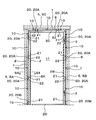
- FIG. 1 is an overall front view of a hinged door device to which a connecting member of a building material according to an embodiment of the present invention is applied.
- FIG. 2 is an overall front view showing a door frame serving as a building material on the hinged door device side.
- FIG. 3 illustrates a structure in which a door frame and a reinforcing member serving as a building material on the skeleton side are connected via an auxiliary member attached to the reinforcing member by a first connecting member and a second connecting member. It is the whole front view shown.
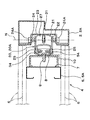
- FIG. 4 is a sectional view taken along line S4-S4 of FIG.
- FIG. 5 is a perspective view showing the entirety of the first connector shown in FIG. 3 including the auxiliary members shown in FIGS. 3 and 4.
- FIG. 6 is a front view of FIG.
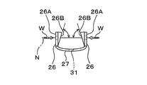
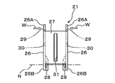
- FIG. 7A is a plan view showing a first connecting member that is a constituent member of the first connecting member and the second connecting member.
- FIG. 7B is a side view showing the first connecting member that is a constituent member of the first connecting member and the second connecting member.
- FIG. 7C is a bottom view showing the first connecting member that is a constituent member of the first connecting member and the second connecting member.
- FIG. 7D is a rear view showing the first connecting member that is a constituent member of the first connecting member and the second connecting member.
- FIG. 8A is a plan view showing the first connecting member when a load is applied.
- FIG. 8B is a side view showing the first connecting member when a load is applied.
- FIG. 8A is a plan view showing the first connecting member when a load is applied.
- FIG. 8B is a side view showing the first connecting member when a load is applied.
- FIG. 8A is a plan view showing the first connecting member when
- FIG. 8C is a bottom view showing the first connecting member when a load is applied.
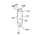
- FIG. 9A is a side view showing a second connecting member that is a constituent member of the first connecting member.
- FIG. 9B is a rear view showing a second connecting member that is a constituent member of the first connecting member.
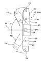
- FIG. 10 is a front view showing, with solid lines, a state in which the first connection member and the second connection member of the first connection member shown in FIGS. 5 and 6 are parallel or substantially parallel.
- FIG. 11 is a side view showing the first connecting member when the first connecting member and the second connecting member are in the state shown by the solid line in FIG.
- FIG. 12 is a sectional view taken along line S12-S12 of FIG. FIG.
- FIG. 13 is a side view showing the first connecting member when the first connecting member and the second connecting member are in a dogleg shape as shown in FIGS. 5 and 6.
- FIG. 14 is a sectional view taken along line S14-S14 of FIG.
- FIG. 15 is a view similar to FIG. 4 showing a state before the first connection member and the second connection member are connected to the auxiliary member attached to the reinforcing member of FIG.
- FIG. 16 is a view similar to FIG. 13, showing a state in which the first connecting member and the second connecting member are connected to the reinforcing member shown by a two-dot chain line by a connecting tool.
- FIG. 17 is a view similar to FIG. 4, showing the state of FIG. FIG.
- FIG. 18 is an enlarged cross-sectional view showing that the first connecting member of the first connecting member is locked on the central shaft serving as the locked member in the states of FIGS. 16 and 17.
- FIG. 19 is the same as FIG. 16 showing a state in which the first connecting member and the second connecting member are connected to the auxiliary member attached to the reinforcing member by the connecting member arranged on the same side in the axial direction of the central axis.
- FIG. FIG. 20 is a view similar to FIG. 4, showing the state of FIG.
- FIG. 21 is a plan sectional view showing the structure of a building to which the coupler shown in FIGS. 19 and 20 can be applied.
- FIG. 1 shows an overall front view of the hinged door device.
- a hinged door 1 is rotatably attached to a door frame 2 around a hinge 3, and the door frame 2 is disposed inside an opening 4 ⁇ / b> A formed in a wall 4 which is a building frame.
- FIG. 2 shows the door frame 2 before the hinged door 1 is attached.
- the door frame 2 is an opening frame whose inside is an entrance 11 that is opened and closed by the hinged door 1.
- the door frame 2 of the present embodiment is a four-sided frame
- the door frame 2 is composed of left and right side frame members 2A and 2B, an upper frame member 2C, and a lower frame member 2D that is a shoe sliding member.
- These frame members 2A, 2B, 2C, and 2D are welded in advance in a factory, and transported to a building site of a building such as a building in which the opening device is installed.
- the door frame 2 may be a three-sided frame in which the lower frame member 2D does not exist.
- FIG. 3 shows an arrangement of the door frame 2 on the wall 4 shown in FIG. 1 and FIG.
- FIG. 4 is a sectional view taken along line S4-S4 of FIG.
- the wall 4 shown in FIGS. 1 and 2 is formed by fastening face members 6 such as gypsum boards on both front and back surfaces of the core member 5, and the building frame is formed. It has become.
- the door frame 2 is arranged inside the opening 4A shown in FIGS.
- the vertical direction is the length direction at a portion facing the left and right side frame members 2 ⁇ / b> A and 2 ⁇ / b> B of the door frame 2 in the left and right direction.
- the core members 5A and 5B arranged vertically and the core member 5C arranged vertically in the left-right direction at a position vertically opposed to the upper frame member 2C of the door frame 2 are shown. I have.
- the reinforcing members 7 shown in FIGS. 3 and 4 are previously joined to the core members 5A, 5B, and 5C.
- an auxiliary member 8 is attached to each of the reinforcing members 7 by a fastening tool 9 shown in FIG.
- a positioning member 10 having a crank shape is connected to each auxiliary member 8. After the positioning members 10 are brought into contact with one of the two sides of the reinforcing member 7 in the thickness direction of the door frame 2 (thickness direction of the hinged door 1 and the wall 4), the auxiliary member 8 is reinforced.
- each auxiliary member 8 is positioned and attached to the reinforcing member 7 at a predetermined position in the thickness direction of the door frame 2.
- the core member 5, the reinforcing member 7, and the auxiliary member 8 are members on the wall 4 side that is a building skeleton, these core member 5, the reinforcing member 7, and the auxiliary member 8 are connected to the skeleton side. Building materials.
- the hinged door 1 and the door frame 2 are members on the hinged door device side installed on the wall 4, the hinged door 1 and the door frame 2 are hinged door device-side building materials.
- FIG. 3 shows a state where the door frame 2 is connected to the reinforcing member 7 via the auxiliary member 8 by the connecting member 20 after the operation of arranging the door frame 2 inside the opening 4A of the wall 4. It is shown.
- a plurality of connecting members 20 are provided for each of the left and right side frame members 2A and 2B and the upper frame member 2C of the door frame 2, and connect the door frame 2 to the reinforcing member 7 via the auxiliary member 8. ing.
- the connecting tool 20 a plurality of first connecting tools 20A and two second connecting tools 20B are used.
- the first connecting member 20A includes a first connecting member 21 and a second connecting member 22, while the second connecting member 20B includes the first connecting member 21 but does not include the second connecting member 22.
- Each of the plurality of first connectors 20A has the same shape and the same structure. For this reason, in FIGS. 5 and 6, among the plurality of first connecting members 20A shown in FIG. 3, they are arranged on the side frame member 2A of the door frame 2 shown in FIG. As a representative example, a first connecting member 20A connecting the side frame member 2A and the auxiliary member 8 attached to the reinforcing member 7 connected to the core member 5A is shown in FIG. 6, the side frame member 2A is omitted.
- the two second connectors 20B shown in FIG. 3 also have the same shape and structure. As shown in FIG. 3, these second connecting members 20B are arranged below the first connecting member 20A, in which a plurality of the second connecting members 20B are vertically arranged on the left and right side frame members 2A, 2B. ing.
- FIG. 5 shows a perspective view of the first connector 20A including the auxiliary member 8.
- FIG. 6 is a front view of FIG.
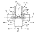
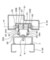
- the first connecting member 20A includes a bearing member 23 formed in a hat shape, a center shaft 24 supported by the bearing member 23, and the first connecting member 21 described above. And the second connecting member 22.
- the center axis 24 has the thickness direction of the door frame 2 in the axial direction N, and both ends in the axial direction N serve as retaining portions 24A to prevent the central shaft 24 from being removed.
- the center shaft 24 is attached to the end of the first connection member 21 and the second connection member 22 on the door frame 2 side, respectively, to the first connection member 21 and the second connection member 22.
- the first connecting member 21 and the second connecting member 22 are rotatable about a central axis 24.
- the end of the first connection member 21 on the wall 4 side is connected to the auxiliary member 8 by a connection tool 25 using a drill screw.
- the end of the second connecting member 22 on the wall 4 side is connected to the auxiliary member 8 by a connecting tool 34 using a drill screw.
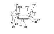
- 7A, 7B, 7C and 7D show the first connecting member 21.
- 7A, 7B, 7C, and 7D are a plan view, a side view, a bottom view, and a rear view of the first connection member 21, respectively.
- the first connecting member 21 is a stamped and bent product of a metal plate.
- the first connecting member 21 is provided with two connecting portions 26 facing each other.
- the two connecting portions 26 are separated from each other in the axial direction N of the central shaft 24 and are connected by a bridging portion 27 having a width in the axial direction N of the central shaft 24.
- the bridging portion 27 is bridging between the ends of the two connecting portions 26 on the thickness direction side of the entire first connecting member 21 orthogonal to the axial direction N of the central shaft 24.
- a longitudinal direction of each connecting portion 26 is provided. Is such that both ends 26A and 26B in the longitudinal direction of the connecting portion 26 reach the door frame 2 and the auxiliary member 8 serving as the frame of the wall 4.
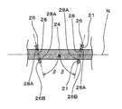
- the end 26A on the auxiliary member 8 side of the two ends 26A and 26B in the length direction of each connecting portion 26 has the axial direction of the central shaft 24.
- a torsion angle ⁇ that is an angle of inclination of the first connecting member 21 to the outside with respect to N is provided.
- This torsion angle ⁇ is a torsion angle in a direction opposite to each other for the two connecting portions 26.
- the end portion 26B on the door frame 2 side is not provided with the twist angle as described above. And between the end part 26A and the end part 26B is an intermediate part 26C for eliminating the torsion angle ⁇ little by little.
- the end 26B on the door frame 2 side is provided with a large-diameter first hole 28 as an insertion portion for inserting the center shaft 24, and the end 26A on the auxiliary member 8 side is shown in FIG.
- a small-diameter second hole 29 for inserting the coupling tool 25 is provided.
- a third hole 30 for inserting couplers 50 and 51, which will be described later with reference to FIGS. 19 and 20, is provided in each connecting portion 26 in a range where the above-mentioned torsion angle ⁇ exists. Has been.
- the bridging portion 27 is provided with a long hole 31.
- the long hole 31 is elongated in the length direction of the connecting portion 26, and serves as a reduced strength portion formed in the bridging portion 27 to reduce the strength of the bridging portion 27.
- the first connecting member 21 has a substantially U-shaped cross section perpendicular to the length direction formed by the two connecting portions 26 and the bridging portion 27 bridging the bridging portions 26. Although it is U-shaped, the ends 26A of the two connecting portions 26 on the auxiliary member 8 side are opened to the outside of the first connecting member 21 due to the torsion angle ⁇ described above. In other words, it has a V shape (inverted @ V-shipped) that opens outward in the axial direction N of the central shaft 24.
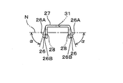
- FIGS. 8A, 8B, and 8C show a state in which loads W in opposite directions in the axial direction N of the central shaft 24 are applied to the end 26A of the connecting portion 26 on the auxiliary member 8 side. I have.
- Such a state occurs when an end 26A of the connecting portion 26 on the auxiliary member 8 side is connected to the auxiliary member 8 by the connecting tool 25 of FIG.
- the end 26B on the side of the door frame 2 connected to the end 26A on the side of the auxiliary member 8 via the intermediate portion 26C has an effect on the axial direction N of the center shaft 24 due to the effect of the load W.
- a torsion angle ⁇ that is an inward inclination angle of the first connecting member 21 is generated.
- the torsion angle ⁇ is a torsion angle in the opposite direction to each of the end portions 26B on the door frame 2 side.
- the shape of the end 26B of each of the two connecting portions 26 on the door frame 2 side is closed to the outside of the first connecting member 21 due to the twist angle ⁇ .
- the shape is inverted V-shaped.
- the bridging portion 27 is provided with the elongated hole 31 to reduce the strength of the bridging portion 27, the bridging portion 27 is easily deformed by the load W due to the load W described above. Therefore, the torsion angle ⁇ at the end 26A on the auxiliary member 8 side is reduced or eliminated, and the torsion angle ⁇ at the end 26B on the door frame 2 side is more reliably generated.
- FIG. 9A and 9B show the second connecting member 22.
- FIG. 9A and 9B are a side view and a rear view of the second connecting member 22, respectively.
- the second connecting member 22 is also a stamped and bent product of a metal plate.
- the second connecting member 22 is also provided with two connecting portions 35 facing each other.
- the two connecting portions 35 are separated from each other in the axial direction N of the central shaft 24 and are connected by a bridging portion 36 having a width in the axial direction N of the central shaft 24.
- the bridging portion 36 is bridging between the ends of the two connecting portions 35 on the thickness direction side of the entire second connecting member 22 orthogonal to the axial direction N of the central shaft 24.
- each connecting portion 35 Is such that both ends 35A and 35B in the longitudinal direction of the connecting portion 35 reach the door frame 2 and the auxiliary member 8 serving as the frame of the wall 4.
- the end 35A on the auxiliary member 8 side is slightly inward of the second connecting member 22 with respect to the end 35B on the door frame 2 side. It is bent.
- the end 35B on the door frame 2 side is provided with a large-diameter first hole 37 as an insertion portion for inserting the center shaft 24, and the end on the auxiliary member 8 side.
- the portion 35A is provided with a small-diameter second hole 38 as an insertion portion for inserting the coupler 34 shown in FIG.
- each connecting portion 35 is also provided with a third hole 39 for inserting couplers 50 and 51 described later with reference to FIGS. 19 and 20.
- a projection 40 protruding toward the central shaft 24, in other words, protruding toward the first connecting member 21 is formed at an end 36B of the bridging portion 36 on the door frame 2 side.
- a notch 41 is provided at an end 36 ⁇ / b> B of the bridging portion 36 at a position near the projecting piece 40.
- two notches 41 are provided at both ends of the projecting piece 40 at the end 36 ⁇ / b> B.
- the protruding piece portion 40 of the present embodiment is formed to be slightly bent from the bridging portion 36 to the inside in the thickness direction of the second connecting member 22.
- the protruding portion 40 formed on the second connecting member 22 in this manner is bent in the thickness direction when a load is applied to the protruding portion 40 in the thickness direction of the entire second connecting member 22. It is possible. Two notches 41 provided on both sides of the projecting portion 40 of the end portion 36B of the bridging portion 36 form a strength reducing portion for reducing the strength of the base end portion of the projecting portion 40 in the bridging portion 27. Therefore, even if the load acting on the projecting piece 40 is small, the projecting piece 40 can be easily bent.
- the first connecting member 20A including the first connecting member 21, the second connecting member 22, the bearing member 23, and the center shaft 24 described above is shown in FIG. 10 (a front view of the first connecting member 20A) and FIG. (A side view of the first connector 20A) is assembled in a factory where the door frame 2 is manufactured. This assembling is performed by inserting the first hole 28 provided in the connecting portion 26 of the first connecting member 21 and the first hole 37 provided in the connecting portion 35 of the second connecting member 22 into a central shaft as a common insertion member. 24, the center shaft 24 is further inserted into a hat-shaped bearing member 23, and a process of forming retaining portions 24A from both ends of the center shaft 24 from the bearing member 23 is performed.
- the center shaft 24 is a male threaded bar having a large number of irregularities formed on the surface by a thread and a thread groove alternately in the axial direction.
- FIG. 12 is a sectional view taken along line S12-S12 in FIG.
- FIG. 12 is a cross-sectional view of the first connecting member 20A assembled by the first connecting member 21, the second connecting member 22, the bearing member 23, and the center shaft 24 as described above.
- the projecting piece 40 formed on the second connecting member 22 is in contact with the back surface 27A of the bridging section 27 provided on the first connecting member 21. . Therefore, the first connecting member 21 and the second connecting member 22 having the central shaft 24 as a common insertion member are connected by the central shaft 24.
- the first connecting member 21 and the second connecting member 22 are arranged in parallel or substantially parallel to each other in a direction orthogonal to the axial direction N of the central shaft 24.
- the protruding piece portion 40 constitutes a parallel means 45 for aligning the first connecting member 21 and the second connecting member 22 in a direction orthogonal to the axial direction N of the central shaft 24 to make them parallel or substantially parallel.
- the parallel connection is performed. Due to the parallel function of the means 45, the first connecting member 21 and the second connecting member 22 are connected to the direction of the distance between the door frame 2 and the auxiliary member 8 and the thickness direction of the door frame 2 (shown in FIGS. 1 and 2).
- the first connector 20A disposed on the side frame members 2A and 2B of the door frame 2 is arranged vertically on the upper frame member 2C of the door frame 2 in a direction perpendicular to the direction perpendicular to the thickness of the wall 4. (In the left-right direction in the first connecting tool 20A), it is possible to make them parallel or substantially parallel.
- the bearing member 23 is welded to the left and right side frame members 2A and 2B and the upper frame member 2C of the door frame 2 by welding or the like, as shown in FIG. By being combined, it is attached to the door frame 2.
- the second connecting tool 20B shown in FIG. 3 includes a first connecting member 21, a bearing member 23, and a center shaft 24. Therefore, the second connecting member 20B has the same structure as the first connecting member 20A with the second connecting member 22 removed.
- Such a second connector 20B is also attached to the door frame 2 at the factory by welding the bearing members 23 to the left and right side frame members 2A and 2B of the door frame 2 by welding or the like.
- the door frame 2 to which the first connector 20A and the second connector 20B are attached at the factory is carried to a work site where the hinged door device of FIG. 1 is installed. Thereafter, before the face member 6 (see FIG. 4) of the wall 4 (see FIG. 2) is attached to the core member 5, the right and left sides between the left and right side frame members 2A and 2B of the door frame 2 and the auxiliary member 8 are formed.
- the first connector 20A and the second connector 20B are inserted at intervals in the direction, and the first connector 20A is inserted between the upper frame member 2C of the door frame 2 and the auxiliary member 8 in the vertical direction. insert.
- the door frame 2 and the first and second connectors 20A and 20B are arranged inside the opening 4A of the wall 4 shown in FIGS.
- the auxiliary member 8 is attached to the reinforcing member 7 connected to the core members 5A, 5B, 5C (see FIG. 3), and forms the wall 4 in FIG.
- the plurality of first connectors 20 ⁇ / b> A are formed.
- the first connecting member 20A inserted between the side frame members 2A and 2B of the door frame 2 and the auxiliary member 8 in the left-right direction has the first connecting member 21 and the second connecting member 22 as center axes. Even if the first connecting member 21 and the second connecting member 22 are separated by the parallel function of the above-described parallel means 45, the space between the side frame members 2A and 2B and the reinforcing member 7 can be rotated even around the center member 24.
- the first connector 20A inserted in the vertical direction between the upper frame member 2C of the door frame 2 and the auxiliary member 8 attached to the reinforcing member 7 coupled to the core member 5C also includes:
- the parallel function of the paralleling means 45 the first connecting member 21 and the second connecting member 22 are perpendicular to the vertical direction, which is the distance between the upper frame member 2C and the reinforcing member 7, and the thickness direction of the door frame 2. It can be made parallel or substantially parallel while being aligned in the left and right directions.
- the first connecting member 21 and the second connecting member 22 of the first connecting member 20A are rotatable about the central axis 24, and the side frame members 2A and 2B, the reinforcing member 7 and , Or the vertical space between the upper frame member 2C and the reinforcing member 7 is small, the first connector 20A can be effectively inserted into these spaces.
- the first connection member 21 of the second connection tool 20B is set upright with the center axis 24 of the second connection tool 20B as the center. Since the operation can be completed easily and in a short time by a small number of workers, workability can be improved.
- FIG. 13 shows a side view of the first coupling tool 20A after the rotation operation has been performed.
- FIG. 14 is a cross-sectional view of the first connector 20A taken along line S14-S14 in FIG.
- the protruding piece 40 provided on the second connecting member 22 and abutting on the back surface 27A of the bridging portion 27 of the first connecting member 21 performs the above-described turning operation.
- the second linking member 22 bends from the connection point with the bridging portion 36 due to the load due to the turning work by the operator, and thus the parallel function of the paralleling means 45 disappears.
- the first connecting member 20A inserted into the space between the side frame members 2A and 2B and the reinforcing member 7 has the first connecting member 21 and the second connecting member 22.
- the inclination angles ⁇ 1 and ⁇ 2 with respect to the left-right direction M which is the direction of the interval between the side frame members 2A and 2B and the reinforcing member 7 are angles opposite to each other.
- the auxiliary member 8 can be inserted between the ends 26A on the auxiliary member 8 side and between the ends 35A (see FIG. 15). Further, with respect to the first connecting member 20A inserted in the space between the upper frame member 2C and the auxiliary member 8, the first connecting member 21 and the second connecting member 22 are connected to the space between the upper frame member 2C and the reinforcing member 7. The first connection member 21 and the second connection member 22 are rotated by rotating about the central axis 24 so that the inclination angles with respect to the vertical direction are opposite to each other. The auxiliary members 8 can be inserted between the ends 26A of the portions 26 and 35 on the auxiliary member 8 side and between the ends 35A.
- the first connecting member 21 is arranged in the direction of the space between the side frame members 2A and 2B and the auxiliary member 8 and the direction of the space between the upper frame member 2C and the auxiliary member 8.
- the second connecting member 22 has an inclination angle with respect to the direction of the interval between the side frame members 2A and 2B and the auxiliary member 8 and the direction of the interval between the upper frame member 2C and the auxiliary member 8. And the inclination angle of the first connecting member is opposite to the inclination angle of the first connecting member.
- the strength of the second connecting member 22 is reduced on both sides of the projecting portion 40 provided on the second connecting member 22. Since two notches 41 are formed, even if the load of the above-described turning operation for bending the protruding piece portion 40 from the connection portion of the second connecting member 22 with the bridging portion 36 is small, the worker Can bend the protruding piece 40 more reliably.
- the center shaft 24, which is a component of the first connector 20A, allows the first connecting member 21 and the second connecting member 22 of the first connector 20A to rotate freely.
- the first connecting member 21 and the second connecting member 22 are commonly inserted members. For this reason, compared with a case where the first connection member 21 and the second connection member 22 are individually provided with a center axis that allows the first connection member 21 and the second connection member 22 to be rotatable, the first connection member 21 and the second connection member 22 are different from each other.
- the number of members constituting the tool 20A can be reduced. Thereby, the structure can be simplified and the manufacturing cost can be reduced.
- the worker connects the two coupling members 25 (see FIGS. 4 and 13) of the first coupling member 20A (see FIG. 3) to the first coupling member 21.
- the end of the first connecting member 21 on the auxiliary member 8 side is inserted into the second hole 29 (see FIGS. 7A, 7B and 7C) provided in the connecting portion 26 and screwed into the auxiliary member 8.
- two coupling tools 34 are connected to a second hole 38 (see FIGS. 9A and 9B) provided in the coupling portion 35 of the second coupling member 22 of the first coupling tool 20A. .)
- the end of the second connecting member 22 on the auxiliary member 8 side is also connected to the auxiliary member 8 as shown in FIGS. 16 and 17.
- each of the two second connectors 20B (see FIG. 3) disposed at the lowermost portions of the left and right side frame members 2A and 2B of the door frame 2.
- the inclination angle (see FIG. 10) of the first connecting member 21 with respect to the left-right direction M described above is determined by the first connecting member 20A described above.
- the end of the first connecting member 21 on the auxiliary member 8 side is connected to the auxiliary member 8 using two connecting members 25 with the same or substantially the same inclination angle ⁇ 1 as the first connecting member 21.
- the door frame 2 is connected to the first connecting member 20A for each of the plurality of first connecting members 20A. 21 are connected via two connecting portions 35 of the second connecting member 22 and two connecting portions 20B of the first connecting member 21 are respectively connected to the two second connecting members 20B. It is connected to the auxiliary member 8 via the connecting portions 35.
- the first connecting member 20A inserted into the space between the side frame members 2A and 2B and the reinforcing member 7 is such that the first connecting member 21 is connected to the side frame member.
- the inclination angle ⁇ 1 formed with respect to the left-right direction M which is the direction of the interval between 2A, 2B and the reinforcing member 7, and the inclination angle ⁇ 2 formed by the second connecting member 22 with respect to the left-right direction M are opposite to each other. Because of such an attitude (see FIG. 10), the door frame 2 is connected to the auxiliary member 8 in a vertically immovable state.
- the first connecting member 20A inserted into the space between the upper frame member 2C and the auxiliary member 8 has the first connecting member 21 in the direction of the space between the upper frame member 2C and the reinforcing member 7. Since the inclination angle with respect to the vertical direction and the inclination angle with respect to the vertical direction of the second connecting member 22 are opposite to each other, the door frame 2 is It is also immovable in the left-right direction and connected.
- each of the first connecting members 21 of the first connecting member 20 ⁇ / b> A on the auxiliary member 8 side is set to the first position.
- the load W from the coupling tool 25 acts on the end 26A of the connecting portion 26 on the auxiliary member 8 side.
- the torsion angle ⁇ existing at the end 26A on the auxiliary member 8 side decreases or disappears, and the end on the door frame 2 side which is the end opposite to the end 26A.
- the portion 26B has a twist angle ⁇ as described above.
- FIG. 18 is an enlarged cross-sectional view of the end 26B showing that such a torsion angle ⁇ occurs at the end 26B of the first connection member 21 on the door frame 2 side of each connection portion 26.
- a torsion angle ⁇ is generated at the end 26 ⁇ / b> B of the connection portion 26 of each of the first connection members 21 on the door frame 2 side
- the torsion angle ⁇ changes in the axial direction of the central shaft 24. Since the angle is inclined with respect to N, the hole 28 serving as an insertion portion provided at the end 26 ⁇ / b> B on the door frame 2 side for inserting the center shaft 24 is also provided in the axial direction N of the center shaft 24.
- the corner 28 ⁇ / b> A of the hole 28 is locked to the surface of the central shaft 24.
- the central shaft 24 is a locked member to which the corner 28A of the hole 28 is locked.
- the first connecting member 20A of which the first connecting member 21 is a constituent member moves in the thickness direction of the door frame 2 which is the axial direction N of the central shaft 24. It becomes immobile.
- the door frame 2 is immovably connected to the auxiliary member 8 serving as the building-side building material in the thickness direction of the door frame 2 and is connected thereto.
- the central shaft 24 serving as the locked member of the present embodiment is a male threaded bar having a large number of irregularities formed on the surface by the thread and the thread groove alternately in the axial direction.
- the corner 28 ⁇ / b> A of the hole 28 is more securely locked to the surface of the center shaft 24, whereby the door frame 2 is more securely immobilized with respect to the auxiliary member 8 in the thickness direction of the door frame 2. It can be connected in a state.
- the first connecting member 21 and the second connecting member 22 are connected to the auxiliary member 8 by the above-described connecting members 25 and 34.
- the auxiliary member 8 is positioned and attached to the reinforcing member 7 at a predetermined position in the thickness direction of the door frame 2 by the positioning member 10 shown in FIG.
- the door frame 2 is positioned and arranged at a predetermined position in the thickness direction of the door frame 2.
- the load W (see FIG. 8A and FIG. 8A) of the two connecting portions 26 of the first 8B.) Acts on the bridging portion 27 provided on the first connecting member 21 in the thickness direction of the bridging portion 27, as described with reference to FIGS. 8A, 8B, and 8C.
- deformation such as bending in a direction protruding outward from the first connecting member 21 occurs, and a twist angle ⁇ is generated at the end 26B of each of the first connecting members 21 on the door frame 2 side.
- the bridging portion 27 is provided with the elongated hole 31 serving as a strength reduction portion for reducing the strength of the bridging portion 27, the bending of the bridging portion 27 due to the load W is performed. And the like will occur more reliably, and as a result, the torsion angle ⁇ of the end 26B on the door frame 2 side will also occur more reliably.
- two ends 26A and 35A on the auxiliary member 8 side of the two connecting portions 26 and 35 of the first connecting member 21 and the second connecting member 22 of the first connecting member 20A are each two.
- these couplers 25 and 34 are arranged on the opposite sides of the center axis 24 in the axial direction N with respect to the first connection member 21 and the second connection member 22, respectively.
- the ends 26A and 35A on the auxiliary member 8 side are connected to the auxiliary member 8 in opposite directions in the axial direction N of the central shaft 24.
- the end 26A of the two connecting portions 26 of the first connecting member 21 of the first connecting member 20A on the auxiliary member 8 side is used as the auxiliary member 8.
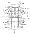
- One coupling 25 and another coupling 50 different from the coupling 25 are used for coupling.
- These couplers 25 and 50 are arranged on the same side of the center axis 24 in the axial direction N with respect to the first connecting member 21, and have the same direction in the axial direction N.
- the coupling 50 is opposite to the side of the two connecting portions 26D and 26E where the couplings 25 and 50 are arranged in the axial direction N of the central shaft 24.
- connection tool 51 is used. These couplers 34 and 51 are also arranged on the same side in the axial direction N of the central shaft 24 with respect to the second connecting member 22 and have the same direction in the axial direction N.
- the coupling tool 51 is located on the side of the two connecting portions 35 opposite to the side where the coupling tools 34 and 51 are arranged in the axial direction N of the central shaft 24. This is a connecting tool for inserting the connecting portion 35D and drawing it toward the connecting portion 35E.
- these couplings 50 and 51 include heads 50A and 51A, small-diameter shaft portions 50B and 51B extending forward from these heads 50A and 51A, and small diameters thereof. It is a tapping screw including large-diameter male screw portions 50C and 51C extending forward from the shaft portions 50B and 51B.
- the diameters of the third holes 30, 39 provided in the first connection member 21 and the second connection member 22 shown in FIGS. 7A to 7D and 9B are larger than the diameters of the large-diameter male screw portions 50C, 51C. It is small and larger than the diameter of the small diameter shaft portions 50B, 51B.
- one of the two connecting portions 26D, 26E, 35D, and 35E of the first connecting member 21 and the second connecting member 22 is rotated while the connecting tools 50 and 51 are rotated by the tool.
- the fasteners 50 and 51 are inserted into the third holes 30 and 39 of the holes 26E and 35E and moved forward, female screws by the large-diameter male screw portions 50C and 51C are formed on the inner surfaces of the third holes 30 and 39.
- the coupling portions 26D, 35D on the side opposite to the side where the couplings 25, 34, 50, 51 are arranged in the axial direction N of the central shaft 24.
- the third holes 30, 39 are also provided with female screws formed by the large-diameter male screw portions 50C, 51C.
- the small diameter shaft portions 50B, 51B of the couplings 50, 51 reach the third holes 30, 39 of the coupling portions 26E, 35E on the same side as the side where the couplings 25, 34, 50, 51 are arranged.
- the small diameter shaft portions 50B, 51B rotate idly.
- the connecting parts 26D, 35D on the side opposite to the side on which the couplings 25, 34, 50, 51 are arranged, the couplings 25, 34, 50, 51 are arranged by the large-diameter male screw parts 50C, 51C.
- the connecting portions 26E and 35E on the same side as the connecting side.
- the coupling members 25, 34, 50 and 51 are disposed among the ends 26 A and 35 A on the auxiliary member 8 side.
- the end portions 26A and 35A on the opposite side to the side where they are pressed are strongly pressed by the auxiliary member 8.
- a state similar to the state where these ends 26A and 35A are connected to the auxiliary member 8 is obtained.
- all the ends 26A and 35A on the auxiliary member 8 side of the connecting portions 26 and 35 of the first connecting member 21 and the second connecting member 22 of the first connecting member 20A are connected to the auxiliary member 8.
- the work for rotating and moving forward these couplings 25, 34, 50, 51 with a tool can also be performed by an operator who is on the same side in the axial direction N of the central shaft 24. , And the work time can be shortened, and the workability of the work can be improved.
- the third holes 30 are provided in each of the two connecting portions 26D and 26E of the first connecting member 21 in the first connecting member 20A and the second connecting member 20B. Further, a third hole 39 is provided in each of the two connecting portions 35D and 35E of the second connecting member 22 in the first connecting tool 20A. Therefore, unlike the example shown in FIG. 19, the coupling tools 25, 34, 50, and 51 may be arranged on the side of the connection portion 26D of the first connection member 21 and on the side of the connection portion 35D of the second connection member 22. It is possible. Therefore, the side on which the couplers 25, 34, 50, 51 are arranged can be arbitrarily selected according to the state of each installation site of the swing door device.
- the connectors 25, 34, 50, 51 are provided. Can be arranged on the same side in the thickness direction of the door frame 2 to connect the door frame 2 to the auxiliary member 8 of the wall 4.
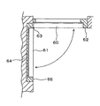
- FIG. 21 shows a structure of a building or the like in which it is effective to arrange all the couplings 25, 34, 50, and 51 on the same side in the axial direction N of the central axis 24, as described with reference to FIGS.
- the fire door 61 which normally opens the entrance 60 inside the door frame 62, includes the hinge 63 as a center, the door frame 62, and the door pocket 65 for storing the fire door 61 when closed. It can be opened and closed freely between them.
- the door pocket 65 is connected to a rear wall 64 having a large thickness dimension. In order to connect the door pocket 65 to the rear wall 64, the first connecting tool 20A and the second connecting tool 20B and the connecting tools 25, 34, 50, and 51 shown in FIGS.
- the present invention relates to two building materials disposed at intervals, specifically, building materials on the skeleton side such as a wall, and building materials on the device side, for example, an opening frame such as a door frame of a hinged door device or a sliding door device. , Can be used to connect
- a bridging part, 28 for inserting a central shaft Hole serving as an insertion portion, 31 ... a long hole serving as a portion where the strength of the bridging portion is reduced, ⁇ , ⁇ : torsion angles, ⁇ 1, ⁇ 2 Tilt angle, the horizontal direction is the direction of M ... interval, N ... axial, W ... load.
Landscapes
- Engineering & Computer Science (AREA)
- Civil Engineering (AREA)
- Structural Engineering (AREA)
- Mechanical Engineering (AREA)
- Joining Of Building Structures In Genera (AREA)
- Door And Window Frames Mounted To Openings (AREA)
- Hinges (AREA)
Abstract
Selon la présente invention, une première extrémité (26B) d'une partie de liaison (26) d'un élément de liaison (21) atteint un élément verrouillé (24) positionné dans une direction axiale N qui est la direction d'épaisseur de l'un de deux matériaux de construction, et une seconde extrémité (26A) de l'élément de liaison (26) atteint l'autre des deux matériaux de construction. La seconde extrémité (26A) est formée de manière à avoir un angle de torsion α à un angle d'inclinaison par rapport à la direction axiale N. Si la seconde extrémité (26A) est reliée à l'autre matériau de construction au moyen d'un raccord de liaison, l'angle de torsion α est réduit ou éliminé, un angle de torsion par rapport à la direction axiale N est généré au niveau de la première extrémité (26B), la première extrémité (26B) se verrouille avec l'élément verrouillé (24), et l'élément de liaison (21) relie les deux matériaux de construction. Par conséquent, il est possible de faciliter et d'améliorer la maniabilité du travail de liaison de deux matériaux de construction positionnés avec un intervalle entre eux, et de réaliser un tel travail en une courte période.
Priority Applications (4)
| Application Number | Priority Date | Filing Date | Title |
|---|---|---|---|
| US17/257,614 US11746585B2 (en) | 2018-07-05 | 2019-07-02 | Connection member for construction materials, connecting fitting therefor, connecting structure therefor, and connecting method therefor |
| CN201980045122.3A CN112654761B (zh) | 2018-07-05 | 2019-07-02 | 用于建筑材料的连接构件、连接配件、连接结构及连接方法 |
| AU2019298545A AU2019298545B2 (en) | 2018-07-05 | 2019-07-02 | Connecting member for construction materials, connecting fitting therefor, connecting structure therefor, and connecting method therefor |
| EP19830876.9A EP3819455B1 (fr) | 2018-07-05 | 2019-07-02 | Élément de liaison pour matériaux de construction, raccord de liaison associé, structure de liaison associée, et procédé de liaison associé |
Applications Claiming Priority (2)
| Application Number | Priority Date | Filing Date | Title |
|---|---|---|---|
| JP2018128165A JP7032254B2 (ja) | 2018-07-05 | 2018-07-05 | 建材の連結部材、その連結具、その連結構造及びその連結方法 |
| JP2018-128165 | 2018-07-05 |
Publications (1)
| Publication Number | Publication Date |
|---|---|
| WO2020009101A1 true WO2020009101A1 (fr) | 2020-01-09 |
Family
ID=69060419
Family Applications (1)
| Application Number | Title | Priority Date | Filing Date |
|---|---|---|---|
| PCT/JP2019/026256 Ceased WO2020009101A1 (fr) | 2018-07-05 | 2019-07-02 | Élément de liaison pour matériaux de construction, raccord de liaison associé, structure de liaison associée, et procédé de liaison associé |
Country Status (7)
| Country | Link |
|---|---|
| US (1) | US11746585B2 (fr) |
| EP (1) | EP3819455B1 (fr) |
| JP (1) | JP7032254B2 (fr) |
| CN (1) | CN112654761B (fr) |
| AU (1) | AU2019298545B2 (fr) |
| TW (2) | TWI772895B (fr) |
| WO (1) | WO2020009101A1 (fr) |
Families Citing this family (9)
| Publication number | Priority date | Publication date | Assignee | Title |
|---|---|---|---|---|
| JP7032254B2 (ja) | 2018-07-05 | 2022-03-08 | 文化シヤッター株式会社 | 建材の連結部材、その連結具、その連結構造及びその連結方法 |
| JP7068078B2 (ja) | 2018-07-05 | 2022-05-16 | 文化シヤッター株式会社 | 建材の連結具及びその連結方法 |
| US11746586B2 (en) | 2019-04-05 | 2023-09-05 | Bunka Shutter Co., Ltd. | Connecting device for construction materials, connecting structure therefor, and connecting method therefor |
| CA3058114A1 (fr) * | 2019-09-11 | 2021-03-11 | Sound Seal, Inc. | Porte a isolation sonore |
| JP7531321B2 (ja) * | 2020-06-12 | 2024-08-09 | 文化シヤッター株式会社 | 建材の連結具及びその連結方法 |
| JP7360362B2 (ja) * | 2020-06-17 | 2023-10-12 | 文化シヤッター株式会社 | 建材の連結装置、その連結構造及びその連結方法 |
| JP7105832B2 (ja) * | 2020-07-17 | 2022-07-25 | 文化シヤッター株式会社 | 建材の連結具、その連結構造及びその連結方法 |
| WO2023058223A1 (fr) * | 2021-10-08 | 2023-04-13 | 文化シヤッター株式会社 | Instrument d'assemblage de matériaux de construction, et structure ainsi que procédé d'assemblage associés |
| US20240200392A1 (en) * | 2022-12-14 | 2024-06-20 | Pella Corporation | Shimming concepts for fenestration units |
Citations (5)
| Publication number | Priority date | Publication date | Assignee | Title |
|---|---|---|---|---|
| JPS4874432U (fr) * | 1971-12-17 | 1973-09-17 | ||
| JPH0610585U (ja) | 1992-07-15 | 1994-02-10 | 文化シヤッター株式会社 | ドアユニット |
| JPH0913800A (ja) * | 1995-06-27 | 1997-01-14 | Matsushita Electric Works Ltd | 間仕切り用の開口枠の構造 |
| KR20090008920A (ko) * | 2007-07-19 | 2009-01-22 | 이승득 | 건축용 창틀 지지구 |
| JP2017115463A (ja) * | 2015-12-25 | 2017-06-29 | 文化シヤッター株式会社 | 建材の連結構造及びその連結方法 |
Family Cites Families (56)
| Publication number | Priority date | Publication date | Assignee | Title |
|---|---|---|---|---|
| US1458025A (en) * | 1921-01-20 | 1923-06-05 | Carl F Biele | Adjustable jamb unit |
| US1718813A (en) * | 1928-06-11 | 1929-06-25 | Ira S Finley | Door jamb |
| US2284074A (en) * | 1939-07-01 | 1942-05-26 | John M Stahl | Adjustable jamb for shower stall doors |
| US2859491A (en) * | 1956-02-07 | 1958-11-11 | John F Penkala | Adjustable jamb |
| US3250049A (en) * | 1963-12-20 | 1966-05-10 | Sklar Samuel | Adjustable wall clamping means for door bucks |
| US3518794A (en) * | 1968-12-30 | 1970-07-07 | William Horner | Doorframe having adjustable jamb |
| US3571996A (en) * | 1969-04-07 | 1971-03-23 | Mesker Brothers Ind Inc | Doorframe |
| US3585770A (en) * | 1969-06-06 | 1971-06-22 | Maizler Iron Works Inc | Steel door frame |
| US3685226A (en) * | 1970-05-05 | 1972-08-22 | Stanley H Richter | Adjustable door jamb |
| JPS4854432U (fr) | 1971-10-22 | 1973-07-13 | ||
| JPS5214368Y2 (fr) | 1972-03-14 | 1977-03-31 | ||
| JPS547147B2 (fr) | 1972-05-24 | 1979-04-04 | ||
| US4128977A (en) * | 1973-11-05 | 1978-12-12 | Schubeis Ewald I E | Door frame, especially for fireproof doors |
| JPS5310127Y2 (fr) * | 1973-11-19 | 1978-03-17 | ||
| US3906671A (en) * | 1974-03-20 | 1975-09-23 | Tex Steel Corp | Adjustable door frame |
| JPS6017338B2 (ja) | 1978-06-05 | 1985-05-02 | 利昌工業株式会社 | 接着方法 |
| JPS54182562U (fr) | 1978-06-14 | 1979-12-24 | ||
| JPS54182561U (fr) | 1978-06-15 | 1979-12-24 | ||
| JPS6013981Y2 (ja) | 1979-12-28 | 1985-05-04 | 神鋼アルフレツシユ株式会社 | 既設の旧窓枠に新窓枠を取付ける装置 |
| JPS6013982Y2 (ja) | 1979-12-28 | 1985-05-04 | 神鋼アルフレツシユ株式会社 | 既設の旧窓枠に新窓枠を取付ける装置 |
| JPS614626Y2 (fr) | 1979-12-28 | 1986-02-13 | ||
| JPS56107069U (fr) | 1980-01-17 | 1981-08-20 | ||
| US4453346A (en) * | 1982-05-24 | 1984-06-12 | United States Gypsum Company | Adjustable wall jamb for shower door |
| JPS5980082U (ja) | 1982-11-20 | 1984-05-30 | 瀬良垣 稔 | 溶接アンカ−金具 |
| JPS5982184U (ja) | 1982-11-26 | 1984-06-02 | 山崎産業株式会社 | アルミサツシ窓枠の取付調整具 |
| JPS59233085A (ja) | 1983-06-13 | 1984-12-27 | 株式会社間組 | サツシユ取付構造 |
| DE8400332U1 (de) * | 1984-01-07 | 1984-03-29 | SCHÜCO Heinz Schürmann GmbH & Co, 4800 Bielefeld | Eck- oder stossverbinder fuer bauprofile |
| US4873804A (en) * | 1988-10-11 | 1989-10-17 | Pioneer Industries, Division Of Core Industries, Inc. | Drywall frame compression anchor assembly and frame |
| JP2617877B2 (ja) * | 1994-02-21 | 1997-06-04 | 博 橘▲高▼ | 中間開度保持機能を備えた蝶番 |
| JP3215604B2 (ja) * | 1995-06-27 | 2001-10-09 | 松下電工株式会社 | 間仕切り用の開口枠の構造 |
| JPH09184397A (ja) | 1995-12-28 | 1997-07-15 | Ishikawajima Constr Materials Co Ltd | 接合構造 |
| US5655343A (en) * | 1996-07-09 | 1997-08-12 | Fred Seals Construction, Inc. | Apparatus and method for an adjustable shim for doors and windows |
| IT1301841B1 (it) | 1998-06-30 | 2000-07-07 | Hydro Aluminium Systems Spa | Elemento di connessione per un profilato composito e profilatocomposito comprendente detto elemento di connessione |
| US6216402B1 (en) * | 1999-08-19 | 2001-04-17 | Van De Laar Kevin | Window installation system |
| JP3469152B2 (ja) * | 1999-12-24 | 2003-11-25 | 新日軽株式会社 | 面付け型窓枠における密封材の装着構造 |
| CN2744811Y (zh) | 2004-11-05 | 2005-12-07 | 罗拥军 | 活动防护门窗之伸缩机构的连接片 |
| JP2006307633A (ja) | 2005-03-30 | 2006-11-09 | Noda Corp | 扉枠調整具及び扉枠取付構造 |
| US7987637B2 (en) * | 2006-09-25 | 2011-08-02 | Smith Patrick J | Adjustable shim |
| CN101498399B (zh) | 2008-01-28 | 2011-09-28 | 刘易辉 | 一种型材连接装置及采用该型材连接装置的型材设备 |
| CN201460561U (zh) * | 2009-06-30 | 2010-05-12 | 东莞市坚朗五金制品有限公司 | 具有轴承枢接机构的连杆 |
| CN201460560U (zh) * | 2009-06-30 | 2010-05-12 | 东莞市坚朗五金制品有限公司 | 具有自动动作机构的连杆 |
| JP5177569B2 (ja) * | 2009-08-27 | 2013-04-03 | キャタピラー エス エー アール エル | ヒンジおよびドア装置 |
| US8806812B2 (en) * | 2010-01-27 | 2014-08-19 | Black Mountain Door, Llc | Adjustable door frame assembly and method of installation |
| US9010704B2 (en) * | 2010-02-16 | 2015-04-21 | Andrew Sirek | Adjustment device and system |
| KR101225620B1 (ko) * | 2011-01-20 | 2013-01-25 | 최원겸 | T자형 볼트가 연결된 좌우상하 조절형 문틀 고정장치 |
| JP5681509B2 (ja) | 2011-01-25 | 2015-03-11 | 旭化成ホームズ株式会社 | 建具枠調整具及び建具枠調整構造 |
| US9194170B2 (en) * | 2013-03-15 | 2015-11-24 | Therma-Tru Corp. | Jamb installation device and method |
| JP6262485B2 (ja) | 2013-10-02 | 2018-01-17 | 文化シヤッター株式会社 | 差圧用ドア装置 |
| TWM488540U (zh) | 2014-05-20 | 2014-10-21 | zong-zheng Ke | 拉摺門銜接鉸鍊之摺疊定位具可調頂掣壓力之構造 |
| JP2015224482A (ja) | 2014-05-28 | 2015-12-14 | 株式会社Ihi | 免震構造 |
| JP5946870B2 (ja) * | 2014-08-08 | 2016-07-06 | ニチハ株式会社 | 止水部材及び外壁構造 |
| JP6774183B2 (ja) | 2015-12-25 | 2020-10-21 | 文化シヤッター株式会社 | 建材の位置出し構造及びその位置出し方法 |
| US10415299B2 (en) * | 2016-12-29 | 2019-09-17 | Endura Products, Inc. | Adjustable shim and pre-hung door with the same |
| JP6895359B2 (ja) | 2017-06-30 | 2021-06-30 | 文化シヤッター株式会社 | 建材のすき間調整装置 |
| CN207749946U (zh) | 2017-08-30 | 2018-08-21 | 深圳市固诺建材有限公司 | 双曲柄连杆式活动链接装置 |
| JP7032254B2 (ja) * | 2018-07-05 | 2022-03-08 | 文化シヤッター株式会社 | 建材の連結部材、その連結具、その連結構造及びその連結方法 |
-
2018
- 2018-07-05 JP JP2018128165A patent/JP7032254B2/ja active Active
-
2019
- 2019-07-02 EP EP19830876.9A patent/EP3819455B1/fr active Active
- 2019-07-02 WO PCT/JP2019/026256 patent/WO2020009101A1/fr not_active Ceased
- 2019-07-02 CN CN201980045122.3A patent/CN112654761B/zh active Active
- 2019-07-02 US US17/257,614 patent/US11746585B2/en active Active
- 2019-07-02 AU AU2019298545A patent/AU2019298545B2/en active Active
- 2019-07-04 TW TW109132272A patent/TWI772895B/zh active
- 2019-07-04 TW TW108123607A patent/TWI705181B/zh active
Patent Citations (5)
| Publication number | Priority date | Publication date | Assignee | Title |
|---|---|---|---|---|
| JPS4874432U (fr) * | 1971-12-17 | 1973-09-17 | ||
| JPH0610585U (ja) | 1992-07-15 | 1994-02-10 | 文化シヤッター株式会社 | ドアユニット |
| JPH0913800A (ja) * | 1995-06-27 | 1997-01-14 | Matsushita Electric Works Ltd | 間仕切り用の開口枠の構造 |
| KR20090008920A (ko) * | 2007-07-19 | 2009-01-22 | 이승득 | 건축용 창틀 지지구 |
| JP2017115463A (ja) * | 2015-12-25 | 2017-06-29 | 文化シヤッター株式会社 | 建材の連結構造及びその連結方法 |
Also Published As
| Publication number | Publication date |
|---|---|
| AU2019298545B2 (en) | 2021-10-28 |
| AU2019298545A1 (en) | 2021-02-11 |
| CN112654761B (zh) | 2022-08-05 |
| CN112654761A (zh) | 2021-04-13 |
| EP3819455B1 (fr) | 2024-09-11 |
| JP7032254B2 (ja) | 2022-03-08 |
| TWI705181B (zh) | 2020-09-21 |
| JP2020007748A (ja) | 2020-01-16 |
| TWI772895B (zh) | 2022-08-01 |
| TW202006236A (zh) | 2020-02-01 |
| US20210140225A1 (en) | 2021-05-13 |
| EP3819455A1 (fr) | 2021-05-12 |
| EP3819455A4 (fr) | 2021-12-22 |
| TW202117168A (zh) | 2021-05-01 |
| US11746585B2 (en) | 2023-09-05 |
Similar Documents
| Publication | Publication Date | Title |
|---|---|---|
| JP7032254B2 (ja) | 建材の連結部材、その連結具、その連結構造及びその連結方法 | |
| WO2020009103A1 (fr) | Raccord de liaison pour matériaux de construction et son procédé de production | |
| JP7128863B2 (ja) | 建材の連結構造及びその連結具 | |
| JP7105822B2 (ja) | 建材の連結具、その連結構造及びその連結方法 | |
| JP7105832B2 (ja) | 建材の連結具、その連結構造及びその連結方法 | |
| JP7105821B2 (ja) | 建材の連結具、その連結構造及びその連結方法 | |
| JP7085588B2 (ja) | 建材の連結構造及びその連結具 | |
| JP7085589B2 (ja) | 建材の連結構造 | |
| JP7360362B2 (ja) | 建材の連結装置、その連結構造及びその連結方法 | |
| JP7445472B2 (ja) | 建材の連結作業方法 | |
| HK40038977A (en) | Connecting fitting for construction materials and method for connecting same | |
| HK40040890B (en) | Connecting member, connecting fitting, connecting structure, and connecting method for construction materials | |
| HK40040890A (en) | Connecting member, connecting fitting, connecting structure, and connecting method for construction materials | |
| JP2021147767A (ja) | 建材用連結具の操作工具 | |
| HK40038977B (en) | Connecting fitting for construction materials and method for connecting same | |
| WO2023058223A1 (fr) | Instrument d'assemblage de matériaux de construction, et structure ainsi que procédé d'assemblage associés | |
| JP2021195766A (ja) | 建材の連結具、その連結構造及びその連結方法 |
Legal Events
| Date | Code | Title | Description |
|---|---|---|---|
| 121 | Ep: the epo has been informed by wipo that ep was designated in this application |
Ref document number: 19830876 Country of ref document: EP Kind code of ref document: A1 |
|
| NENP | Non-entry into the national phase |
Ref country code: DE |
|
| WWE | Wipo information: entry into national phase |
Ref document number: 2019830876 Country of ref document: EP |
|
| ENP | Entry into the national phase |
Ref document number: 2019298545 Country of ref document: AU Date of ref document: 20190702 Kind code of ref document: A |