WO2020009106A1 - 情報処理装置および情報処理方法 - Google Patents
情報処理装置および情報処理方法 Download PDFInfo
- Publication number
- WO2020009106A1 WO2020009106A1 PCT/JP2019/026277 JP2019026277W WO2020009106A1 WO 2020009106 A1 WO2020009106 A1 WO 2020009106A1 JP 2019026277 W JP2019026277 W JP 2019026277W WO 2020009106 A1 WO2020009106 A1 WO 2020009106A1
- Authority
- WO
- WIPO (PCT)
- Prior art keywords
- area
- objects
- information processing
- setting
- screen
- Prior art date
- Legal status (The legal status is an assumption and is not a legal conclusion. Google has not performed a legal analysis and makes no representation as to the accuracy of the status listed.)
- Ceased
Links
Images






Classifications
-
- G—PHYSICS
- G06—COMPUTING OR CALCULATING; COUNTING
- G06F—ELECTRIC DIGITAL DATA PROCESSING
- G06F3/00—Input arrangements for transferring data to be processed into a form capable of being handled by the computer; Output arrangements for transferring data from processing unit to output unit, e.g. interface arrangements
- G06F3/01—Input arrangements or combined input and output arrangements for interaction between user and computer
- G06F3/048—Interaction techniques based on graphical user interfaces [GUI]
- G06F3/0481—Interaction techniques based on graphical user interfaces [GUI] based on specific properties of the displayed interaction object or a metaphor-based environment, e.g. interaction with desktop elements like windows or icons, or assisted by a cursor's changing behaviour or appearance
-
- G—PHYSICS
- G09—EDUCATION; CRYPTOGRAPHY; DISPLAY; ADVERTISING; SEALS
- G09G—ARRANGEMENTS OR CIRCUITS FOR CONTROL OF INDICATING DEVICES USING STATIC MEANS TO PRESENT VARIABLE INFORMATION
- G09G5/00—Control arrangements or circuits for visual indicators common to cathode-ray tube indicators and other visual indicators
-
- G—PHYSICS
- G09—EDUCATION; CRYPTOGRAPHY; DISPLAY; ADVERTISING; SEALS
- G09G—ARRANGEMENTS OR CIRCUITS FOR CONTROL OF INDICATING DEVICES USING STATIC MEANS TO PRESENT VARIABLE INFORMATION
- G09G5/00—Control arrangements or circuits for visual indicators common to cathode-ray tube indicators and other visual indicators
- G09G5/36—Control arrangements or circuits for visual indicators common to cathode-ray tube indicators and other visual indicators characterised by the display of a graphic pattern, e.g. using an all-points-addressable [APA] memory
-
- G—PHYSICS
- G09—EDUCATION; CRYPTOGRAPHY; DISPLAY; ADVERTISING; SEALS
- G09G—ARRANGEMENTS OR CIRCUITS FOR CONTROL OF INDICATING DEVICES USING STATIC MEANS TO PRESENT VARIABLE INFORMATION
- G09G5/00—Control arrangements or circuits for visual indicators common to cathode-ray tube indicators and other visual indicators
- G09G5/36—Control arrangements or circuits for visual indicators common to cathode-ray tube indicators and other visual indicators characterised by the display of a graphic pattern, e.g. using an all-points-addressable [APA] memory
- G09G5/38—Control arrangements or circuits for visual indicators common to cathode-ray tube indicators and other visual indicators characterised by the display of a graphic pattern, e.g. using an all-points-addressable [APA] memory with means for controlling the display position
Definitions
- the present disclosure relates to an information processing device and an information processing method.
- Patent Document 1 Japanese Patent Application Laid-Open No. 2005-31835
- Patent Document 1 Japanese Patent Application Laid-Open No. 2005-31835
- the information processing apparatus arranges the objects and sets properties (appearance, etc.) of each object, and then performs a drag-and-drop operation using a mouse and the object. It is necessary to align the position of the object using the alignment function. For this reason, when the number of objects increases, the number of operations required for positioning the objects increases significantly.
- the present disclosure has been made in view of the above problems, and an object of the present disclosure is to provide an information processing apparatus and an information processing method capable of reducing the trouble when a user creates screen data of a programmable display. It is in.
- the information processing apparatus is an operation receiving unit that receives a drag-and-drop operation of dragging an object and dropping the object in a drawing area provided in a display screen of the information processing apparatus;
- the image processing apparatus includes drawing means for drawing an object dropped on the drawing area, and screen data generating means for generating screen data of a screen to be displayed on the programmable display based on the drawing of the object.
- the user does not need to perform an operation of aligning the first object and the second object. Therefore, it is possible to reduce the trouble when the user creates the screen data of the programmable display.
- the drawing means arranges the third object at the position where the third object is dropped.
- the third object is arranged at the position where the third object is dropped.
- different processing can be executed depending on whether the position where the object is dropped is the first area or the second area.
- the information processing apparatus further includes a display control means for displaying a setting screen for setting the arrangement mode of the objects on the display screen.
- a display control means for displaying a setting screen for setting the arrangement mode of the objects on the display screen.
- the drawing unit moves the first object and the second object in the horizontal direction of the first area. Line up.
- the drawing unit moves the first object and the second object in the vertical direction of the first area. Line up.
- the first object and the second object can be aligned in the horizontal or vertical direction according to the setting on the setting screen.
- the display control means further displays an icon on the display screen.
- the icon is clicked in a state where the first object and the second object are aligned in one of the horizontal direction and the vertical direction, the drawing unit causes the first object and the second object to be aligned. In the other of the horizontal and vertical directions.
- the user can switch the arrangement of the first object and the second object from the horizontal direction to the vertical direction or from the vertical direction to the horizontal direction by simply clicking the icon. It becomes.
- the drawing means may connect the first object with the first object at the upper end position in the first area.
- the second object and the second object are aligned in the horizontal direction, and when the second position setting is further performed on the setting screen, the first object and the second object are positioned at the center position in the first area.
- the third position is further set on the setting screen in the horizontal direction, the first object and the second object are horizontally aligned at the lower end position in the first area.
- the first object and the second object are laterally aligned at any of the upper end position, the center position, and the lower end position in the first area according to the setting on the setting screen. Can be done.
- the drawing means may associate the first object with the first object at the left end position in the first area.
- the second object and the second object are aligned in the vertical direction, and the fifth position is further set on the setting screen, the first object and the second object are aligned at the center position in the first area.
- the sixth position setting is further performed on the setting screen, the first object and the second object are vertically aligned at the right end position in the first area.
- the first object and the second object are vertically aligned at any one of the left end position, the center position, and the right end position in the first area according to the setting on the setting screen. Can be done.
- the size of the object is fixed according to the type of the object.
- the drawing unit may display the plurality of objects in two or more lines or two lines by a wrapping process. Sort by more than columns.
- a plurality of objects can be aligned in the horizontal direction or the horizontal direction without changing the size of the objects.
- the drawing unit sets a size of each of the plurality of objects in order to display the objects in one line or one column. Make it smaller.
- the information processing apparatus further includes a change unit that changes the size of the first area based on the operation.
- the drawing unit determines that the plurality of objects cannot be arranged in one line or one column by reducing the size of the first region. Are arranged in one row or one column by reducing the size of each of.
- the user even when the user performs the operation of narrowing the first area, the user does not need to perform the operation of changing the position and the size of the object so that the object is contained in one row or one column. Therefore, the user's work load for changing the screen design can be reduced.
- the drawing unit may determine the size of the first area after the expansion. , The size of each of the plurality of objects is increased.
- the drawing means changes the size of each object according to the size of the first area and the number of objects dropped in the first area.
- the user can obtain screen data in which a plurality of objects are arranged without performing an operation of changing the size of each object.
- the information processing apparatus when the information processing apparatus receives an input for designating a range in the drawing area in a state where the first area is not set, the information processing apparatus generates an arrangement and a size of one or more objects included in the designated range as a template. Further, there is provided a template generating means for performing the processing.
- the information processing apparatus further includes a setting unit that sets an address or a variable to the object according to the order in which the objects are dropped in the first area.
- addresses and variables can be automatically assigned at the same time as the arrangement of objects, so that the number of steps required for the user's screen design can be significantly reduced.
- the information processing method includes a step of receiving a drag-and-drop operation of dragging an object and dropping the object in a drawing area provided in the display screen; and Drawing the object, and generating screen data of a screen to be displayed on the programmable display based on the drawing of the object.
- the step of drawing when a second object as an object is dragged to a preset area in a state where the first object as an object is arranged in a preset area in the drawing area, The first object and the second object are aligned in a preset area.
- the user does not need to perform an operation of aligning the first object and the second object. Therefore, it is possible to reduce the trouble when the user creates the screen data of the programmable display.
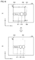
- FIG. 4 is a diagram illustrating an example of a process of generating screen data of a programmable display.
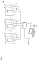
- FIG. 1 is a schematic diagram illustrating a PLC system according to an embodiment.
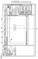
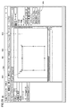
- FIG. 4 is a diagram illustrating an example of a screen displayed on a display of a PC by executing an application used when creating screen data of a programmable display.
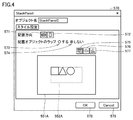
- FIG. 9 is a diagram for describing a setting example on a setting screen.
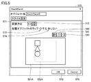
- FIG. 9 is a diagram for explaining another example of setting on the setting screen.
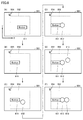
- FIG. 9 is a state transition diagram for explaining an alignment process.
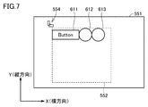
- FIG. 3 is a diagram for explaining an arrangement mode of objects.
- FIG. 3 is a diagram for explaining an arrangement mode of objects.
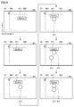
- FIG. 9 is a transition diagram for explaining an alignment process.
- FIG. 1 is a schematic diagram illustrating a PLC system according to an embodiment.
- FIG. 4 is a diagram illustrating an example of a screen displayed on a display of a PC by executing
- FIG. 3 is a diagram for explaining an arrangement mode of objects.
- FIG. 3 is a diagram for explaining an arrangement mode of objects.
- FIG. 7 is a diagram for explaining a switching operation of an object alignment direction. It is a figure for explaining object return processing performed when the number of objects increases.
- FIG. 9 is a diagram for describing object wrapping processing performed when an operation of narrowing a layout frame is performed.
- FIG. 9 is a diagram for describing an object reduction process performed when the number of objects increases.
- FIG. 9 is a diagram for describing an object reduction process performed when an operation of narrowing a layout frame is performed.
- FIG. 11 is a diagram for describing an object enlargement process performed when an operation of enlarging a layout frame is performed.
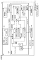
- FIG. 2 is a block diagram illustrating a functional configuration of a PC.
- FIG. 4 is a flowchart for explaining a flow of processing executed by the PC.
- FIG. 2 is a schematic diagram illustrating a hardware configuration of a PC.
- FIG. 9 is a state transition diagram for explaining an alignment process.
- FIG. 14 is a state transition diagram for explaining another example of the alignment processing.
- FIG. 4 is a diagram illustrating a display screen of a PC.
- FIG. 24 is a diagram illustrating a display screen displayed on the PC after FIG. 23.
- FIG. 25 is a diagram illustrating a display screen displayed on the PC after FIG. 24.
- FIG. 26 is a diagram illustrating a display screen displayed on the PC after FIG. 25.
- FIG. 27 is a diagram illustrating a display screen displayed on the PC after FIG. 26.
- FIG. 2 is a block diagram illustrating a functional configuration of a PC.
- FIG. 4 is a diagram illustrating a display screen of a PC.
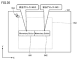
- FIG. 30 is a diagram illustrating a drawing area of a display screen displayed on the PC after FIG. 29.
- FIG. 2 is a block diagram illustrating a functional configuration of a PC.
- FIG. 1 is a diagram illustrating an example of a process of generating screen data of a programmable display.
- the information processing apparatus sets a drawing area (drawing area) on the display screen of the information processing apparatus by executing the drawing function.
- the drawing area includes a first area and a second area.
- the first area is set by a user operation.
- a region other than the first region in the drawing region is automatically determined as the second region along with the setting of the first region.
- the information processing apparatus receives a drag-and-drop operation of dragging an object and dropping the object in the drawing area. Further, the information processing apparatus draws the dropped object in the drawing area.
- the information processing apparatus accepts dragging of object # 1 and dropping of object # 1 on the first area in the drawing area.
- the information processing apparatus shifts the position of the object # 1 from the dragged position to another position (for example, as shown in the state (B)). , The left end of the first area).
- the information processing apparatus accepts the drag of the object # 2 and the drop of the object # 2 on the first area.
- the information processing apparatus aligns the object # 1 and the object # 2 in the first area by moving the position of the object # 2 as shown in a state (D).
- the information processing apparatus aligns object # 1 and object # 2 so as to be arranged in the horizontal direction of the display screen (the direction of the X axis in the drawing).
- the state (F) The object # 3 is arranged at the position where the object # 3 is dropped as shown in FIG. That is, the concession processing device does not execute the alignment processing of the object # 3 outside the first area.
- the information processing device generates screen data of a screen to be displayed on the programmable display based on the drawing of the object.
- the generated data is typically transmitted from the information processing device to the programmable display.
- the generated data is stored in a programmable display using a storage medium such as a USB (Universal Serial Bus) memory.
- the information processing apparatus sets the object # 1 and the object # 2 in the first region.
- the user does not need to perform an operation of arranging the objects # 1 and # 2. Therefore, it is possible to reduce the trouble when the user creates the screen data of the programmable display.
- FIG. 2 is a schematic diagram showing the PLC system 1000 according to the present embodiment.
- PLC system 1000 includes a plurality of PLCs 1, 2, 3, a programmable display 4, and a PC (Personal Computer) 5 as an information processing device.
- PC Personal Computer
- Each of the PLCs 1 to 3 typically includes a CPU unit 10 which is a main body for executing a program, a power supply unit 12 for supplying power to the CPU unit 10 and the like, and an IO (Input / Output) for exchanging signals from a field. And a unit 14.
- the IO unit 14 is connected to the CPU unit 10 via the system bus 11.
- the IO unit 14 acquires an input signal from the detection sensor 6 which is a field device, and drives the relay 7 which is a field device according to a result of execution of a program in the CPU unit 10.
- the programmable display 4 plays a role as a GUI (Graphical User Interface) in an HMI (Human Machine Interface) environment.
- the programmable display 4 includes an operation unit such as a touch panel, a display unit such as a liquid crystal display, a communication unit that communicates with the CPU unit 10, and a control unit that controls each unit.
- Each of the PLCs 1 to 3 can change various settings in accordance with the operation of the operation unit of the programmable display 4, and can display predetermined information of the PLC on the programmable display 4.
- the PC 5 is connected to the programmable display 4.
- the PC 5 has a function of monitoring the operating states of the connected PLCs 1 to 3 and the values of various data.
- the PC 5 When causing the PC 5 to function as a support device, the PC 5 generates programs to be executed by the PLCs 1 to 3 and setting information. Further, the PC 5 may have a debugging function or a simulation function to assist a user in generating an executable program.
- the PLCs 1 to 3 communicate with the programmable display 4 by any one of, for example, FINS (Factory Interface Network Service) communication, HTTP (Hyper Text Transfer Transfer Protocol) communication, or EIP (EtherNet / IP) communication.
- FINS Vectory Interface Network Service
- HTTP Hyper Text Transfer Transfer Protocol
- EIP EtherNet / IP
- FIG. 3 is a diagram illustrating an example of a screen displayed on the display of the PC 5 by executing an application used when creating screen data of the programmable display.
- display screen 550 of PC 5 has a drawing area (drawing area) 551 for drawing (drawing) by the user.
- a drawing area drawing area
- an area 552 an example of a “first area” inside the layout frame
- an area 553 outside the layout frame an example of the “second area”.
- a rectangle indicated by a dotted line represents a layout frame.
- the area 552 in the layout frame is referred to as an “in-frame area 552”, and the area 553 outside the layout frame is also referred to as an “out-of-frame area 553”.
- An icon 554 is displayed in the drawing area 551. The function assigned to the icon 554 will be described later.
- the display screen 550 has a tool box.
- the toolbox includes, for example, a button tool 556, a lamp tool 557, a graphic tool 558, a standard control tool 559, a gauge tool 560, an HMI control tool 561, a custom tool 562, It has a conveyor tool 563 and a tank tool 564.
- the button tool 556 includes a tool 5561 for drawing a “set button”, a tool 5562 for drawing a “toggle button”, a tool 5563 for drawing a “button” (normal button), and “ It has a tool 5564 for drawing a “momentary button” and a tool 5565 for drawing a “reset button”.
- Each of the “set button”, “toggle button”, “button”, “momentary button”, and “reset button” is an example of an object.
- FIG. 3 shows a state where the PC 5 is performing a drag and drop operation by the user. Specifically, the state immediately before the drag operation is performed by selecting the tool 5563 with the mouse and the button object 601 is dragged into the area 551 is shown.
- the objects are aligned in the in-frame area 552. That is, the layout processing is executed within the layout frame.
- a setting screen for setting the arrangement mode will be described, and then, a specific example of the arrangement will be described.
- the setting screen is displayed on the display screen 550 based on a user operation.
- FIG. 4 is a diagram for explaining a setting example on the setting screen.
- the setting screen 570 includes icons 571 and 572 for setting an arrangement direction, radio buttons 573 and 574 for setting whether to wrap (return) the arranged object, and an area corresponding to the drawing area 551. 551A, an area 552A corresponding to the in-frame area 552, icons 575, 576, 577 relating to the position, and buttons 578, 579.
- the example of the setting screen 570 in FIG. 4 shows a state in which the icon 571 is selected.
- the PC 5 arranges the objects arranged in the in-frame area 552 in the horizontal direction.
- the example of the setting screen 570 in FIG. 4 shows a state where the icon 575 is selected.
- the PC 5 arranges the objects arranged in the frame area 552 at the upper end position in the frame area 552.
- the PC 5 horizontally aligns the objects arranged in the frame area 552 at the center position in the frame area 552. Further, when the icon 577 is selected while the icon 571 is selected, the PC 5 horizontally aligns the objects arranged in the frame area 552 at the lower end position in the frame area 552.
- the PC 5 displays the selected arrangement direction and the selected position using three sample figures (square, triangle, and circle in the figure) so that the user can easily confirm the setting contents.
- the PC 5 confirms the settings set by the user.
- the button 579 is selected by the user, the PC 5 discards the current settings.
- FIG. 5 is a diagram for explaining another setting example on the setting screen.
- an example of this setting screen 570 shows a state where icon 572 is selected.
- the PC 5 vertically aligns the objects arranged in the in-frame area 552.
- the example of the setting screen 570 in FIG. 5 shows a state where the icon 580 is selected.
- the PC 5 arranges the objects arranged in the frame area 552 at the left end in the frame area 552.
- the PC 5 vertically aligns the objects arranged in the frame area 552 at the center position in the frame area 552. Further, when the icon 582 is selected in a state where the icon 572 is selected, the PC 5 vertically aligns the objects arranged in the frame area 552 at the right end in the frame area 552.
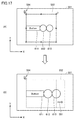
- FIG. 6 is a state transition diagram for explaining the sorting process when the icon 571 and the icon 576 (see FIG. 4) are in the selected state on the setting screen 570. That is, FIG. 6 is a state transition diagram when the arrangement in the horizontal direction and the center position is selected.
- PC 5 receives the drag of object 611 and the drop of object 611 on framed area 552 in drawing area 551.
- the PC 5 moves the position of the object 611 from the dragged position to the center left end of the in-frame area 552 as shown in the state (B). And move.
- the PC 5 receives the drag of the object 612 and the drop of the object 612 on the area 552 within the frame.
- the PC 5 moves the position of the object 612 so that the object 611 and the object 612 are laterally aligned from the left end side at the center position in the frame area 552.
- the PC 5 receives the drag of the object 613 and the drop of the object 613 on the area 552 within the frame.
- the PC 5 moves the position of the object 613 to move the object 611, the object 612, and the object 613 laterally from the left end side at the center position in the frame area 552 as shown in the state (F). Align.
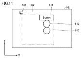
- FIG. 7 is a view for explaining the arrangement of the objects 611, 612, and 613 when the icon 571 and the icon 575 (see FIG. 4) are in a selected state on the setting screen 570. That is, FIG. 7 is a state transition diagram when the arrangement in the horizontal direction and the upper end position is selected.
- PC 5 moves object 613 to move object 611, object 612, and object 613 within framed area 552. At the upper end position, align horizontally from the left end.
- FIG. 8 is a view for explaining the arrangement of the objects 611, 612, and 613 when the icon 571 and the icon 577 (see FIG. 4) are selected on the setting screen 570.
- FIG. 8 is a state transition diagram when the arrangement in the horizontal direction and the lower end position is selected.
- PC 5 when accepting the drop of object 613 to frame area 552, PC 5 moves object 613 to move object 611, object 612, and object 613 within frame area 552. At the lower end position, align horizontally from the left end.
- FIG. 9 is a transition diagram for explaining the alignment processing when the icon 572 and the icon 581 (see FIG. 5) are in the selected state on the setting screen 570. That is, FIG. 9 is a state transition diagram when the arrangement in the vertical direction and the center position is selected.
- PC 5 receives the drag of object 611 and the drop of object 611 on framed area 552 in drawing area 551.
- the PC 5 moves the position of the object 611 from the dragged position to the center upper end position of the in-frame area 552 as shown in the state (B). And move.
- the PC 5 receives the drag of the object 612 and the drop of the object 612 on the area 552 within the frame.
- the PC 5 moves the position of the object 612 so that the object 611 and the object 612 are vertically aligned at the center position in the frame area 552 from the upper end side.
- the PC 5 receives the drag of the object 613 and the drop of the object 613 on the area 552 within the frame.
- the PC 5 moves the position of the object 613 to move the object 611, the object 612, and the object 613 in the vertical direction from the upper end at the center position in the frame area 552 as shown in the state (F). Align.
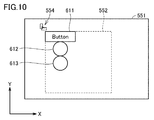
- FIG. 10 is a diagram for explaining the arrangement of the objects 611, 612, and 613 when the icon 572 and the icon 580 (see FIG. 5) are in the selected state on the setting screen 570. That is, FIG. 10 is a state transition diagram when the arrangement in the vertical direction and the left end position is selected.
- PC 5 when accepting the drop of object 613 in frame area 552, PC 5 moves object 613 to move object 611, object 612, and object 613 in frame area 552. At the left end, align vertically from the top.
- FIG. 11 is a view for explaining the arrangement of the objects 611, 612, and 613 when the icon 572 and the icon 582 (see FIG. 5) are in a selected state on the setting screen 570. That is, FIG. 11 is a state transition diagram when the arrangement in the vertical direction and the right end position is selected.
- PC 5 when accepting the drop of object 613 in frame area 552, PC 5 moves object 613 to move object 611, object 612, and object 613 in frame area 552. At the right end, align vertically from the top.
- the operation of displaying setting screen 570 and selecting icon 572 is completed in a state where a plurality of objects are horizontally arranged as in state (F) of FIG. 6, for example. Then, the PC 5 vertically aligns the plurality of objects, for example, as shown in the state (F) of FIG. Similarly, when the operation of displaying the setting screen 570 and selecting the icon 571 is completed in a state where a plurality of objects are aligned in the vertical direction as in the state (F) of FIG. A plurality of objects are horizontally aligned as shown in a state (F).
- the user When the user selects one of the icons 575, 576, 577 (see FIG. 4) in a state where one or more objects are arranged in the in-frame area 552, the user moves the position corresponding to the selected icon. To move the object. For example, when the state where icon 576 is selected is changed to the state where icon 575 is selected, PC 5 changes the position of the object from the state (F) in FIG. 6 to the state in FIG. 7, for example.
- the user selects one of the icons 580, 581, 582 (see FIG. 5) in a state where one or more objects are arranged in the frame area 552, the user is associated with the selected icon. Move the object to a position. For example, when switching from the state where icon 581 is selected to the state where icon 580 is selected, PC 5 changes the position of the object from the state (F) in FIG. 9 to the state in FIG. 10, for example.
- the user can change the alignment direction and the position of the object even during the drawing. Therefore, since it is not necessary to start drawing again from the beginning, it is possible to reduce the work load on the user.
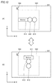
- FIG. 12 is a diagram for explaining a switching operation of the object alignment direction.
- state (A) shows state (F) in FIG. That is, in the state (A) of FIG. 12, the object 611, the object 612, and the object 613 are laterally aligned from the left end side at the center position in the frame area 552.
- the state (B) shows the state (F) in FIG. That is, in the state (B) of FIG. 12, the object 611, the object 612, and the object 613 are vertically aligned from the upper end at the center position in the frame area 552.
- the PC 5 switches the arrangement mode of the objects 611, 612, and 613 in the frame area 552 from the state (A) to the state (B). That is, the PC 5 changes from the horizontal arrangement to the vertical arrangement.
- PC 5 switches the arrangement of objects 611, 612, and 613 in frame area 552 from state (B) to state (A). . That is, the PC 5 changes from the vertical arrangement to the horizontal arrangement.
- the user can sequentially switch between the horizontal arrangement and the vertical arrangement only by clicking the icon 554. For this reason, a series of operations, such as starting up the setting screen 570 and clicking the icons 571 and 572 (see FIG. 4 and the like) related to the arrangement direction, become unnecessary. Therefore, the user's work load for changing the screen design can be reduced.
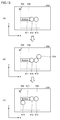
- FIG. 13 is a diagram for explaining object return processing performed when the number of objects increases. In this example, it is assumed that the size of the object is fixed according to the type of the object.
- object 611, object 612, and object 613 are laterally aligned from the left end side at the center position in frame area 552.
- the PC 5 receives the drag of the object 614 and the drop of the object 614 on the area 552 within the frame. In this case, the PC 5 determines whether or not the four objects 611, 612, 613, and 614 fit in one line based on the size of the object 614 (in this case, the size in the horizontal direction).
- the PC 5 determines that the data cannot be accommodated, the PC 5 executes the return processing as shown in the state (C). Specifically, the position of the object 614 is moved to the left end of the in-frame area 552 and below the object 611 at the left end. In this case, the objects 611, 612, and 613 are also moved upward (Y direction) so that the object group including the objects 611, 612, 613, and 614 is located at the center position of the in-frame area 552.
- the PC 5 when aligning a plurality of objects in the in-frame area 552, the PC 5 aligns the plurality of objects in two or more lines by a wrapping process when it cannot be displayed in one line. According to such a configuration, the objects can be aligned in the horizontal direction without changing the size of the objects.
- the present invention is not limited to this.
- the present invention can also be applied to a configuration in which vertical alignment is performed. More specifically, when aligning a plurality of objects in the frame area 552, the PC 5 aligns the plurality of objects in two or more rows by a wrapping process when the plurality of objects cannot be displayed in one line.
- FIG. 14 is a diagram for explaining the object return processing performed when an operation of narrowing the layout frame is performed (that is, when the area 552 in the frame is narrowed).
- the PC 5 when aligning a plurality of objects in the in-frame area 552, the PC 5 aligns the plurality of objects in two or more lines by a wrapping process when it cannot be displayed in one line.
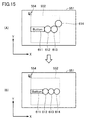
- FIG. 15 is a diagram for describing an object reduction process performed when the number of objects increases.
- state (A) in a state where objects 611, 612, and 613 are aligned in the horizontal direction, a drag of object 614 and a drop of object 614 on framed area 552 are accepted. .
- the PC 5 determines whether or not the four objects 611, 612, 613, and 614 fit in one line based on the size of the object 614 (in this case, the size in the horizontal direction).
- the PC 5 determines that the size cannot be accommodated, the PC 5 executes a process of reducing the size of all the objects 611, 612, 613, and 614 as shown in the state (B). Typically, the objects 611, 612, 613, and 614 are reduced so that the objects 611, 612, 613, and 614 are arranged in one line and fit in the in-frame area 552.
- the PC 5 when aligning the plurality of objects in the frame area 552, the PC 5 reduces the size of each of the plurality of objects in order to display them in one line. According to such a configuration, the objects can be aligned in one row in the horizontal direction. According to this, the user's work load for changing the screen design can be reduced.
- the present invention is not limited to this.
- the present invention can also be applied to a configuration in which vertical alignment is performed. Specifically, when aligning the plurality of objects in the frame area 552, the PC 5 reduces the size of each of the plurality of objects in order to display them in a line.
- FIG. 16 is a diagram for describing an object reduction process performed when an operation of narrowing the layout frame is performed (that is, when the in-frame area 552 is narrowed).
- the PC 5 determines that a plurality of objects cannot be arranged in one line due to the size of the in-frame area 552 being reduced in the horizontal direction in a state where the plurality of objects are arranged in one line, A plurality of objects are arranged in one line by reducing the size of each object. According to such a configuration, even when the user performs an operation of narrowing the in-frame area 552 in the horizontal direction, the user does not need to perform an operation of changing the position and the size of the object to fit in one line. As described above, the user's work load for changing the screen design can be reduced.
- the present invention is not limited to this.
- the present invention can also be applied to a configuration in which vertical alignment is performed. Specifically, when the PC 5 determines that the plurality of objects cannot be arranged in one line due to the size of the in-frame area 552 being reduced in the vertical direction while the plurality of objects are arranged in one line, The plurality of objects are arranged in a line by reducing the size of each of the plurality of objects.
- FIG. 17 is a diagram for explaining an object enlargement process performed when an operation to enlarge the layout frame is performed (that is, when the in-frame area 552 is expanded).
- PC5 When the objects 611, 612, and 613 are aligned in a horizontal line as shown in the state (A), and the layout frame is enlarged in the direction indicated by the arrow 591 as shown in the state (B) , PC5 perform an object enlargement process. Typically, the PC 5 expands the objects 611 to 613 in the vertical and horizontal directions at the same ratio so that the ratio of the total width of the three objects 611 to 613 to the width of the in-frame area 552 is kept constant.
- the PC 5 determines a plurality of objects based on the size of the in-frame area 552 after the enlargement. Increase the size of each of the objects. According to such a configuration, when the user performs an operation of enlarging the in-frame area 552 in the horizontal direction, the user does not need to perform an operation of changing the position and size of each object. As described above, the user's work load for changing the screen design can be reduced.
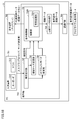
- FIG. 18 is a block diagram for explaining a functional configuration of PC 5.
- PC 5 includes an input device 701, a display device 702, a control unit 703, and a communication IF unit 704.
- the input device 701 includes a keyboard 510 and a mouse 512.
- the control unit 703 controls the overall operation of the PC 5.
- the control unit 703 also functions as a drawing editor.
- the control unit 703 includes an operation reception unit 731, a display control unit 732, a screen data generation unit 733, an area size change unit 734, and an object size change unit 735.
- the display control unit 732 causes the display device 702 to display various screens according to the state of the PC 5.
- the display control unit 732 causes a display screen 550 (see FIG. 3) of the display device 702 to display a setting screen 570 (FIG. 4 or the like) for setting the arrangement mode of the objects based on a user operation.
- the display control unit further displays an icon 554 (see FIG. 3) on the display screen 550 (typically, the drawing area 551).
- the display control unit 732 includes a drawing unit 7320.
- the drawing unit 7320 includes an alignment processing unit 7321.
- the operation accepting unit 731 accepts various user operations via the input device 701. For example, the operation receiving unit 731 receives a drag-and-drop operation of dragging an object and dropping the object on a drawing area 551 provided in the display screen 550 of the PC 5. In addition, the operation receiving unit 731 receives an operation of changing (enlarging or reducing) the size of the layout frame (in other words, the area 552 in the frame). Further, the operation receiving unit 731 receives an operation of changing the position of the layout frame (in other words, the area 552 in the frame).
- the drawing unit 7320 draws the dropped object in the drawing area 551.
- the alignment processing unit 7321 aligns the objects dropped in the in-frame area 552 based on the settings on the setting screen.
- Drawing unit 7320 for example, when a second object (for example, object 612) is dropped in frame area 552 in a state where the first object (for example, object 611) is arranged in frame area 552. , The first object and the second object are aligned in the frame area 552. On the other hand, when the third object is dropped on the out-of-frame area 553, the drawing unit 7320 arranges the third object at the dropped position.
- a second object for example, object 612
- the drawing unit 7320 arranges the third object at the dropped position.
- the screen data generator 733 generates screen data of a screen to be displayed on the programmable display 4 based on the drawing of the object. Specifically, the screen data generation unit 733 receives the drawing data from the drawing unit 7320 and generates the display screen data. The screen data generation unit 733 sends the generated screen data to the communication IF unit 704.
- the communication IF unit 704 transmits screen data to the programmable display 4.
- the object 611 will be described as an example of the first object
- the object 612 will be described as an example of the second object.
- drawing section 7320 drops object 612 when icon 571 is selected on setting screen 570 (when the first direction is set). And the object 611 and the object 612 are aligned in the horizontal direction of the in-frame area 552.
- drawing section 7320 determines that object 612 is dropped when icon 572 is selected on setting screen 570 (when the second direction is set). , The object 611 and the object 612 are aligned in the vertical direction of the in-frame area 552.
- drawing section 7320 displays object 611 and object 612 in a state where object 611 and object 612 are aligned in one of the horizontal direction (X-axis direction) and the vertical direction (Y-axis direction).
- the icon 544 is clicked, the objects 611 and 612 are aligned in the other of the horizontal and vertical directions.
- the drawing unit 7320 performs the following processing when the icon 571 is selected on the setting screen 570 (when the first direction is set) as shown in FIG.
- the drawing unit 7320 sets the upper end position in the frame area 552 at the upper end position.
- the object 611 and the object 612 are aligned in the horizontal direction (see FIG. 7).
- the drawing unit 7320 sets the object 611 and the object 612 at the center position in the frame area 552. Are aligned horizontally (see FIG. 6).
- the drawing unit 7320 sets the object 611 and the object 612 at the lower end position in the frame area 552. Are aligned in the horizontal direction (see FIG. 8).
- the drawing unit 7320 performs the following processing when the icon 572 is selected on the setting screen 570 (when the first direction is set) as shown in FIG.
- the drawing unit 7320 sets the leftmost position in the frame area 552 at the left end position.
- the object 611 and the object 612 are aligned vertically (see FIG. 10).
- the drawing unit 7320 sets the object 611 and the object 612 at the center position in the frame area 552. Are aligned vertically (see FIG. 9).
- drawing unit 7320 sets object 611 and object 612 at the right end position in frame area 552. Are aligned in the vertical direction (see FIG. 11).
- drawing section 7320 Sorts the objects in two or more rows or two or more columns.
- the drawing unit 7320 displays the object in one line or one column. Reduce the size of each of the plurality of objects.
- the drawing unit 7320 performs the following processing.
- drawing unit 7320 reduces the size of framed area 552 so that the plurality of objects are arranged in one row or one column. If it is determined that the plurality of objects cannot be arranged, the plurality of objects are arranged in one row or one column by reducing the size of each of the plurality of objects.
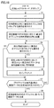
- FIG. 19 is a flowchart for explaining the flow of processing executed by the PC 5.
- step S1 the PC 5 sets the value of the predetermined variable i to 1.
- step S2 the PC 5 receives an operation of dropping the first object in the in-frame area 552.
- step S3 the PC 5 arranges the first object in the in-frame area 552 according to the setting on the setting screen 570 (see state (B) in FIG. 6).
- step S4 the PC 5 determines whether an operation of dropping the (i + 1) th object in the frame area 552 has been received.
- the PC 5 arranges the first to (i + 1) th objects in the frame area 552 in accordance with the settings on the setting screen in step S5.
- PC 5 advances the process to step S7.
- step S6 the PC 5 increments the value of the variable i. That is, the PC 5 increases the value of the variable i by one.
- step S7 the PC 5 determines whether or not an instruction to generate screen data for a programmable display device (user instruction) has been received.
- step S7 When it is determined that the generation instruction has been received (YES in step S7), PC 5 generates screen data (screen data for a display) based on the object in drawing area 551 in step S8. When determining that the generation instruction has not been received (NO in step S7), PC 5 returns the process to step S4.
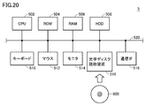
- FIG. 20 is a schematic diagram illustrating a hardware configuration of the PC 5.
- PC 5 executes a CPU 502 that executes various programs including an OS, a ROM (Read Only Memory) 504 that stores a BIOS and various data, and stores data necessary for the CPU 502 to execute the programs.
- a hard disk (HDD) 508 for storing programs executed by the CPU 502 in a nonvolatile manner.
- the PC 5 further includes a keyboard 510 and a mouse 512 for receiving an operation from the user, and a monitor 514 for presenting information to the user. Further, the PC 5 includes a communication interface (IF) 518 for communicating with the programmable display 4 or the like. The PC 5 is communicably connected to the programmable display 4 by a communication IF 518.
- IF communication interface
- a configuration will be described in which the size of an object is changed each time the object is dropped on the in-frame area 552. In the present embodiment, only the differences from the first embodiment will be described, and the description of the common points with the first embodiment will not be repeated.
- FIG. 21 is a state transition diagram for explaining the alignment processing.
- the icon 571 and the icon 576 are in a selected state on the setting screen 570 (see FIG. 4). That is, it is assumed that the arrangement in the horizontal direction and the central position is selected.
- PC 5 accepts the drag of object 621 and the drop of object 621 on framed area 552.
- the PC 5 enlarges the size of the object 621 and moves the position of the object 621 from the position where the object 621 is dragged, as shown in the state (B). It is moved to the center position of the in-frame area 552.
- the PC 5 enlarges the object 621 at the same magnification in the vertical and horizontal directions so that the horizontal width of the in-frame area 552 matches the horizontal width of the object 621.
- the PC 5 receives the drag of the object 622 and the drop of the object 622 on the area 552 within the frame.
- the PC 5 arranges the object 621 and the object 622 in the horizontal direction in order from the left end side at the center position in the frame area 552.
- the PC 5 changes the sizes of the objects 621 and 622 so that the scaling ratios of the object 621 and the object 622 from the default size are the same. More specifically, the PC 5 enlarges or reduces the size of the objects 621 and 622 so that the total width of the two objects 621 and 622 matches the horizontal width of the in-frame area 552. Since the objects 621 and 622 are the same kind of object, they have the same size as shown in the state (D).
- the PC 5 receives the drag of the object 623 and the drop of the object 623 on the area 552 within the frame.
- the PC 5 horizontally aligns the object 621, the object 622, and the object 623 in order from the left end side at the center position in the frame area 552.
- the PC 5 changes the sizes of the objects 621, 622, and 623 so that the scaling ratios of the objects 621, 622, and 623 from the default sizes are the same. More specifically, the PC 5 enlarges or reduces the size of the objects 621, 622, and 623 so that the width of the in-frame area 552 matches the total of the widths of the three objects 621, 622, and 623.
- the PC 5 (specifically, the drawing unit 7320) is configured to change the size of each object according to the size of the in-frame area 552 and the number of objects dropped in the in-frame area 552. Specifically, the PC 5 automatically changes the size of each object so that the size of each object is a size obtained by equally dividing the size of the in-frame area 552 by the number of objects dropped in the in-frame area 552. That is, the PC 5 executes a fitting process for the layout frame. According to this configuration, the user can obtain screen data in which a plurality of objects are arranged without performing an operation of changing the size of each object.
- drawing unit 7320 may be configured to perform a wrapping process when the number of objects increases and if the objects do not fit in a line in the frame area 552 unless they are reduced to the default size or less.
- the setting screen 570 may be configured so that whether or not to perform the above processing can be set.
- FIG. 22 is a state transition diagram for explaining another example of the sorting process. Also in this example, it is assumed that the icon 571 and the icon 576 are in a selected state on the setting screen 570 (see FIG. 4). That is, it is assumed that the arrangement in the horizontal direction and the central position is selected.
- PC 5 accepts the drag of object 621 and the drop of object 621 on framed area 552.
- the PC 5 enlarges the size of the object 621 and moves the position of the object 621 from the position where the object 621 is dragged, as shown in the state (B). It is moved to the center position of the in-frame area 552.
- the PC 5 enlarges the object 621 in the vertical and horizontal directions so that the horizontal width and the height of the in-frame area 552 and the horizontal width and the height of the object 621 match.
- the PC 5 receives the drag of the object 622 and the drop of the object 622 on the area 552 within the frame.
- the PC 5 arranges the object 621 and the object 622 in the horizontal direction in order from the left end side at the center position in the frame area 552.
- the PC 5 changes the sizes of the objects 621 and 622 so that the scaling ratios of the object 621 and the object 622 from the default size are the same. More specifically, the PC 5 enlarges or reduces the size of the objects 621 and 622 in the horizontal direction so that the width of the in-frame area 552 and the total width of the two objects 621 and 622 match. Further, the PC 5 matches the vertical size of the object 622 with the height of the in-frame area 552. Since the objects 621 and 622 are the same kind of object, they have the same size as shown in the state (D).
- the PC 5 receives the drag of the object 623 and the drop of the object 623 on the area 552 within the frame.
- the PC 5 horizontally aligns the object 621, the object 622, and the object 623 in order from the left end side at the center position in the frame area 552.
- the PC 5 changes the sizes of the objects 621, 622, and 623 so that the scaling ratios of the objects 621, 622, and 623 from the default sizes are the same. More specifically, the PC 5 enlarges or reduces the size of the objects 621, 622, and 623 so that the width of the in-frame area 552 matches the total of the widths of the three objects 621, 622, and 623. In addition, the PC 5 matches the vertical size of the object 623 with the height of the in-frame area 552. Since the objects 621, 622, and 623 are the same type of object, they have the same size as shown in the state (F).
- the in-frame area 552 can be filled with one or more objects, and a plurality of objects can be aligned.
- a configuration will be described in which a template relating to the arrangement of objects is generated, and new screen data is generated using the generated template.
- the PC in the present embodiment is referred to as “PC5A” for convenience of description to distinguish it from the PC 5 in the first embodiment.
- the PC 5A has a mechanism in which the position and size (relative position with respect to the selection range, proportionate size) and type of the object within the range selected by the user can be stored as information as a template.
- a mechanism for reading the template information is prepared.
- the PC 5A automatically arranges and sorts the objects of the type defined in the template at the position and size defined in the template in the frame area 552 of the read template. .
- the PC 5A drops the object in the in-frame area 552 into which the template information has been read, and if the type of the object is defined in the template, the PC 5A places the object at a specified position with a specified size.
- the PC 5A automatically changes the size of each object at a fixed rate while maintaining the positional relationship of the objects already arranged in the in-frame area 552. I do.
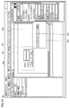
- FIG. 23 is a diagram showing the display screen 550 of the PC 5A.
- the user specifies range 801 in drawing area 551.
- the layout template storage item 803 in the context menu 802 is selected by a click operation with a mouse or the like in a state where the range 801 is specified, the arrangement and size of the objects included in the range 801 are stored as a template.
- the template is stored in a state where it is given a name so that it can be distinguished from other templates.
- the storage location of the template may be the storage location of the file.
- a mechanism that prepares a list such as a library list in the tool and stores the template there may be used.
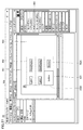
- FIG. 24 is a diagram showing a display screen 550 displayed on the PC 5A after FIG. Referring to FIG. 24, the user sets an in-frame area 552. Thereafter, the user selects an item 805 for applying a layout template in the context menu 804 by a click operation with a mouse or the like. Further, typically, after selecting item 805, the user selects a template. Note that a configuration may be adopted in which a library list of tools is displayed, and a template to be applied is selected from the list.
- FIG. 25 is a diagram showing a display screen 550 displayed on the PC 5A after FIG.
- PC 5A sets element areas 5521, 5522, 5523, 5524, 5525, and 5526 based on the selected template in area 552 within the frame, and sets element areas (specifically, element Area layout frame) is displayed.
- the in-frame area 552 is further divided into a plurality of areas based on the positions and relative sizes of the objects included in the applied template.
- the PC 5A displays the types of objects that can be arranged in the respective element areas 5521 to 5526. For example, in the example of FIG. 25, “Label”, “DataDisplay”, and “Button” are displayed as the types of objects.
- FIG. 26 is a diagram showing a display screen 550 displayed on the PC 5A after FIG. Referring to FIG. 26, the user drags a desired object (“button” in FIG. 26) in a state where the template is applied (the state of FIG. 25), and An operation of dropping the object 631 at the position is performed.
- FIG. 27 is a diagram showing a display screen 550 displayed on the PC 5A after FIG. Referring to FIG. 27, when object 631 is dropped on framed area 552, the object is placed in an element area that matches the type of object 631.
- the object 631 is a button
- the object is arranged in the element area of the button.
- the setting is such that the objects are arranged in order from the left, and no objects are arranged in two of the element areas 5523 and 5526. Therefore, the PC 5A places the object 631 in the element area 5523 on the left side. Deploy. More specifically, the PC 5A enlarges (or reduces) the object 631 so that the object 631 fills (fits) the element area 5523.
- FIG. 28 is a block diagram illustrating a functional configuration of PC 5A.
- PC 5A includes an input device 701, a display device 702, a control unit 703A, a communication IF unit 704, and a template storage unit 705.
- the control unit 703A controls the overall operation of the PC 5A.
- the control unit 703A is different from the control unit 703 of the first embodiment (see FIG. 18) in including a template generation unit 736 and a template reading unit 737. Therefore, the following description focuses on processing in template generating section 736 and template reading section 737, and the contents described in the first embodiment will not be repeated.
- the operation receiving unit 731 receives an input for designating a range in the drawing area 551 in a state where the in-frame area 552 is not set (see FIG. 23).
- the template generation unit 736 generates, as a template, the arrangement and size of one or more objects included in the specified range.
- the template generation unit 736 stores the generated template in the template storage unit 705.
- the drawing unit 7320 draws the in-frame area 552 in the drawing area 551.
- the operation reception unit 731 receives a user operation of displaying a context menu and selecting an item of layout template application (see FIG. 24)
- the PC 5A applies the selected template to the in-frame area 552.
- the template reading unit 737 reads the selected template from the template storage unit 705.
- the template reading unit 737 sends the read template to the drawing unit 7320.
- the drawing unit 7320 displays, based on the template, the element areas of the template in the frame area 552 of the drawing area 551 together with the type name of each element area (see FIG. 25).
- the drawing unit 7320 places the object in an element area of the same type as the type of the object. Fit (see FIG. 27).
- a user creates an application by combining several objects so that certain information can be displayed and set in an easy-to-understand manner. If the object thus combined is convenient and versatile, it can be diverted to a part of a screen used in another programmable display. However, even with the same combination of objects, the appearance (design) often changes according to the programmable display used or the user's preference.
- the PC 5A can provide a mechanism that can save and reproduce the type and size positional relationship of an object for such purposes. Therefore, according to the PC 5A, there is an effect that data diversion is improved and the number of steps required for the user's screen design is reduced.
- Embodiment 4 In the present embodiment, a configuration in which an address or a variable can be set for an object will be described. In the present embodiment, only the differences from the first embodiment will be described, and the description of the common points with the first embodiment will not be repeated. It should be noted that the PC in the present embodiment is referred to as “PC5B” for convenience of description to distinguish it from the PC 5 and the like in the first embodiment.
- FIG. 29 is a diagram showing the display screen 550 of the PC 5B. Referring to FIG. 29, PC 5B displays “assigned address” item 565 as a setting item of area 552 within the frame.
- FIG. 30 is a diagram showing the drawing area 551 of the display screen 550 displayed on the PC 5B after FIG.
- assignment address “W0.0” shown in FIG. 29 is set in object 641.
- the value shown in the item 565 of “assigned address” is incremented to “W0.1”.
- the assigned address “W0.1” is set in the object 641.
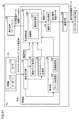
- FIG. 31 is a block diagram illustrating a functional configuration of PC 5B.
- PC 5B includes an input device 701, a display device 702, a control unit 703B, and a communication IF unit 704.
- the control unit 703A controls the overall operation of the PC 5B.
- the control unit 703B is different from the control unit 703 of the first embodiment (see FIG. 18) in including a setting unit 738. Therefore, the following description focuses on the processing in setting section 738, and the contents described in the first embodiment will not be repeated.
- the setting unit 738 includes an address setting unit 7381 and a variable setting unit 7382.
- the address setting unit 7381 assigns an address to the object dropped in the frame area 552. After the assignment, the address setting unit 7381 increments the address.
- the address setting unit 7381 assigns the post-increment address to the object dropped next to the in-frame area 552.
- variable setting unit 7382 sets a variable for the object dropped in the frame area 552. After the assignment, the variable setting unit 7382 automatically increments the last number of several names or automatically increments the element number, as described above. The variable setting unit 7382 allocates the incremented variable to the object dropped next in the in-frame area 552.
- an object for displaying information possessed by a device such as a programmable logic controller (PLC) is arranged.
- PLC programmable logic controller
- addresses and variables can be automatically assigned at the same time as the placement of objects, so that the number of steps required for user screen design can be significantly reduced.
- An information processing device Operation accepting means for accepting a drag-and-drop operation of dragging an object and dropping the object on a drawing area (551) provided in a display screen (550) of the information processing device (5, 5A, 5B) (731)
- Drawing means (7320) for drawing the object dropped in the drawing area (551);
- Screen data generating means for generating screen data of a screen to be displayed on the programmable display based on the drawing of the object;
- the drawing means (7320) places the first object (552) in the first area (552) in the first area (552) in the first area (552).
- An information processing device (5, 5A, 5B) for aligning the first object and the second object in the first area (552) when the second object is dropped.
- the drawing means (7320) When the first direction is set on the setting screen (570), when the second object is dropped, the first object and the second object are moved to the first object. Aligned in the horizontal direction of the area (552), When the second direction is set on the setting screen (570), when the second object is dropped, the first object and the second object are moved to the first object.
- the information processing device (5, 5A, 5B) according to Configuration 1 or 2, wherein the information processing device is aligned in a vertical direction of the region (552).
- the display control means further displays an icon (554) in the display screen,
- the drawing means (7320) clicks on the icon (554) in a state where the first object and the second object are aligned in one of the horizontal direction and the vertical direction.
- the information processing apparatus according to any one of Configurations 1 to 3, wherein the first object and the second object are aligned in the other of the horizontal direction and the vertical direction. , 5B).
- the drawing unit (7320) When the fourth position is further set on the setting screen (570), the first object and the second object are vertically aligned at the left end position in the first area (552). Lined up, When the fifth position setting is further performed on the setting screen (570), the first object and the second object are vertically aligned at the center position in the first area (552). Lined up, When the sixth position setting is further performed on the setting screen (570), the first object and the second object are vertically aligned at the right end position in the first area (552).
- the information processing device (5, 5A, 5B) according to Configuration 5, wherein the information processing device is arranged in a row.
- [Configuration 7] The size of the object is fixed according to the type of the object,
- the drawing means (7320) wraps at least when the plurality of objects including at least the first object and the second object are aligned in the first area (552), and cannot be displayed in one line or one column.
- the information processing apparatus (5, 5A, 5B) according to any one of Configurations 1 to 6, wherein the plurality of objects are arranged in two or more rows or two or more columns by processing.
- the drawing means (7320) reduces the size of the first area (552) so that the plurality of objects are arranged in one row or one column.
- the information processing device according to Configuration 8, wherein when it is determined that the plurality of objects cannot be arranged, the plurality of objects are arranged in one row or one column by reducing the size of each of the plurality of objects.
- the said drawing means (7320) changes the size of each said object according to the size of the said 1st area
- the information processing device according to any one of 1 to 6, wherein the information processing device is an information processing device.
- FIG. 14 An information processing method, Accepting a drag-and-drop operation of dragging an object and dropping the object on a drawing area (551) provided in a display screen (550); Drawing the object dragged into the drawing area (551); Generating screen data of a screen to be displayed on the programmable display (4) based on the drawing of the object, In the step of drawing, the first object as the object is placed in a preset area (552) in the drawing area (551), and the first object is placed in the preset area (552).
- An information processing method wherein, when a second object as an object is dragged, the first object and the second object are aligned in the preset area (552).
- 1, 2, 3 PLC, 4 programmable display 5 PC, 6 detection sensor, 7 relay, 10 CPU unit, 14 IO unit, 11 system bus, 12 power supply unit, 512 mouse, 514 monitor, 544, 554, 571, 572, 575, 576, 577, 580, 581, 582 icons, 550 display screen, 551 drawing area, 551A, 552A area, 552 inside frame area, 553 outside frame area, 556, 557, 558, 559, 560, 561, 562 , 563, 564, 5561, 5562, 5563, 5564, 5565 tool, 565, 803, 805 item, 570 setting screen, 573, 574 radio button, 578, 579 button, 590, 591 arrow, 601, 611, 612 13,614,621,622,623,631,641,642 ⁇ object, 701 ⁇ input device, 702 display device, 703,703A, 703B control unit, 704 communication IF unit, 705 template storage unit, 731 operation reception
Landscapes
- Engineering & Computer Science (AREA)
- Theoretical Computer Science (AREA)
- Physics & Mathematics (AREA)
- General Physics & Mathematics (AREA)
- Computer Hardware Design (AREA)
- General Engineering & Computer Science (AREA)
- Human Computer Interaction (AREA)
- User Interface Of Digital Computer (AREA)
- Controls And Circuits For Display Device (AREA)
Abstract
情報処理装置は、オブジェクトをドラッグし、かつ情報処理装置の表示画面内に設けられた描画領域にオブジェクトをドロップするドラッグ・アンド・ドロップ操作を受け付ける。情報処理装置は、描画領域にドロップされたオブジェクトを描画する。情報処理装置は、オブジェクトの描画に基づき、プログラマブル表示器において表示させる画面の画面データを生成する。情報処理装置は、描画領域内の第1の領域にオブジェクト(#1)が配置されている状態で、第1の領域にオブジェクト(#2)がドロップされると、オブジェクト(#1)とオブジェクト(#2)とを第1の領域内において整列させる。
Description
本開示は、情報処理装置および情報処理方法に関する。
従来、たとえば特開2005-31835号公報(特許文献1)に示すように、複数のオブジェクトを配置することによってプログラマブル表示器の表示画面を生成する作画エディタを有する情報処理装置が知られている。作画エディタにより生成された表示画面は、画面データとしてプログラマブル表示器にダウンロードされる。
プログラマブル表示器の表示画面をユーザが作成する場合には、情報処理装置において、オブジェクトを配置し、かつ各オブジェクトのプロパティ(見た目等)を設定した後に、マウスによるドラッグ・アンド・ドロップ操作およびオブジェクトの整列機能を用いてオブジェクトの位置を合わせる必要がある。このため、オブジェクトの数が多くなると、オブジェクトの位置合わせに必要な手数が非常に多くなる。
本開示は、上記の問題点に鑑みなされたものであって、その目的は、プログラマブル表示器の画面データをユーザが作成する際の手間を削減可能な情報処理装置および情報処理方法を提供することにある。
本開示のある局面に従うと、情報処理装置は、オブジェクトをドラッグし、かつ情報処理装置の表示画面内に設けられた描画領域にオブジェクトをドロップするドラッグ・アンド・ドロップ操作を受け付ける操作受付手段と、描画領域にドロップされたオブジェクトを描画する描画手段と、オブジェクトの描画に基づき、プログラマブル表示器において表示させる画面の画面データを生成する画面データ生成手段とを備える。描画手段は、描画領域内の第1の領域にオブジェクトとしての第1のオブジェクトが配置されている状態で、第1の領域にオブジェクトとしての第2のオブジェクトがドロップされると、第1のオブジェクトと第2のオブジェクトとを第1の領域内において整列させる。
上記の構成によれば、ユーザは、第1のオブジェクトと第2のオブジェクトとを整列させる操作が不要となる。それゆえ、プログラマブル表示器の画面データをユーザが作成する際の手間を削減可能となる。
好ましくは、描画手段は、描画領域内の第2の領域にオブジェクトとしての第3のオブジェクトがドロップされると、当該ドロップされた位置に第3のオブジェクトを配置する。
上記の構成によれば、第2の領域では、ドロップされた位置に第3のオブジェクトを配置される。このように、オブジェクトがドロップされた位置が、第1の領域か第2の領域かで、異なる処理を実行させることができる。
好ましくは、情報処理装置は、オブジェクトの整列態様を設定するための設定画面を表示画面に表示させる表示制御手段をさらに備える。描画手段は、設定画面にて第1の方向設定がなされている場合には、第2のオブジェクトがドロップされると、第1のオブジェクトと第2のオブジェクトとを、第1の領域の横方向に整列させる。描画手段は、設定画面にて第2の方向設定がなされている場合には、第2のオブジェクトがドロップされると、第1のオブジェクトと第2のオブジェクトとを、第1の領域の縦方向に整列させる。
上記の構成によれば、設定画面での設定に応じて、横方向または縦方向に第1のオブジェクトと第2のオブジェクトとを整列させることができる。
好ましくは、表示制御手段は、表示画面内にアイコンをさらに表示する。描画手段は、第1のオブジェクトと第2のオブジェクトとが横方向および縦方向のうちの一方向に整列している状態で、アイコンがクリックされると、第1のオブジェクトと第2のオブジェクトとを横方向および縦方向のうちの他方向に整列させる。
上記の構成によれば、ユーザは、アイコンをクリックするだけで、第1のオブジェクトと第2のオブジェクトとの配列を、横方向から縦方向へ、あるいは縦方向から横方向へと切替えることが可能となる。
好ましくは、描画手段は、第1の方向設定がなされている場合、設定画面にて第1の位置設定がさらになされているときには、第1の領域内の上端位置にて、第1のオブジェクトと第2のオブジェクトとを横方向に整列させ、設定画面にて第2の位置設定がさらになされているときには、第1の領域内の中央位置にて、第1のオブジェクトと第2のオブジェクトとを横方向に整列させ、設定画面にて第3の位置設定がさらになされているときには、第1の領域内の下端位置にて、第1のオブジェクトと第2のオブジェクトとを横方向に整列させる。
上記の構成によれば、設定画面での設定に応じて、第1の領域内の上端位置、中央位置、および下端位置のいずれかで第1のオブジェクトと第2のオブジェクトとを横方向に整列させることができる。
好ましくは、描画手段は、第2の方向設定がなされている場合、設定画面にて第4の位置設定がさらになされているときには、第1の領域内の左端位置にて、第1のオブジェクトと第2のオブジェクトとを縦方向に整列させ、設定画面にて第5の位置設定がさらになされているときには、第1の領域内の中央位置にて、第1のオブジェクトと第2のオブジェクトとを縦方向に整列させ、設定画面にて第6の位置設定がさらになされているときには、第1の領域内の右端位置にて、第1のオブジェクトと第2のオブジェクトとを縦方向に整列させる。
上記の構成によれば、設定画面での設定に応じて、第1の領域内の左端位置、中央位置、および右端位置のいずれかで第1のオブジェクトと第2のオブジェクトとを縦方向に整列させることができる。
好ましくは、オブジェクトのサイズは、オブジェクトの種類に応じて固定されている。描画手段は、少なくとも第1のオブジェクトと第2のオブジェクトとを含む複数のオブジェクトを第1の領域において整列させる場合、一行または一列で表示できないときには、折り返し処理によって複数のオブジェクトを二行以上または二列以上で整列する。
上記の構成によれば、オブジェクトのサイズを変更することなく、複数のオブジェクトを横方向または横方向に整列させることができる。
好ましくは、描画手段は、少なくとも第1のオブジェクトと第2のオブジェクトとを含む複数のオブジェクトを第1の領域において整列させる場合、一行または一列で表示するために、複数のオブジェクトの各々のサイズを小さくする。
上記の構成によれば、画面デザイン変更に対するユーザの作業負担が軽減できる。
好ましくは、情報処理装置は、操作に基づき、第1の領域のサイズを変更する変更手段をさらに備える。描画手段は、複数のオブジェクトが一行または一列で配置されている状態において、第1の領域のサイズが縮小されることにより、複数のオブジェクトが一行または一列で配置できないと判断した場合、複数のオブジェクトの各々のサイズを小さくすることにより複数のオブジェクトを一行または一列で配置する。
好ましくは、情報処理装置は、操作に基づき、第1の領域のサイズを変更する変更手段をさらに備える。描画手段は、複数のオブジェクトが一行または一列で配置されている状態において、第1の領域のサイズが縮小されることにより、複数のオブジェクトが一行または一列で配置できないと判断した場合、複数のオブジェクトの各々のサイズを小さくすることにより複数のオブジェクトを一行または一列で配置する。
上記の構成によれば、ユーザは、第1の領域を狭める操作を行った場合であっても、一行または一列に収めるためにオブジェクトの位置およびサイズを変更する操作を行う必要がなくなる。それゆえ、画面デザイン変更に対するユーザの作業負担が軽減できる。
好ましくは、描画手段は、複数のオブジェクトが一行または一列で配置されている状態において、第1の領域のサイズが行方向または列方向に拡大された場合、当該拡大後の第1の領域のサイズに基づき、複数のオブジェクトの各々のサイズを大きくする。
上記の構成によれば、ユーザは、第1の領域を拡大する操作を行った場合、各オブジェクトの位置およびサイズを変更する操作を行う必要がなくなる。それゆえ、画面デザイン変更に対するユーザの作業負担が軽減できる。
好ましくは、描画手段は、第1の領域のサイズと、第1の領域にドロップされるオブジェクトの数とに応じて各オブジェクトのサイズを変更する。
上記の構成によれば、ユーザは、各オブジェクトのサイズを変更する操作を行うことなく、複数のオブジェクトが整列した画面データを得ることができる。
好ましくは、情報処理装置は、第1の領域が設定されていない状態で描画領域において範囲を指定する入力を受け付けると、指定された範囲に含まれる1以上のオブジェクトの配置およびサイズをテンプレートとして生成するテンプレート生成手段をさらに備える。
上記の構成によれば、データ流用性を向上させ、ユーザの画面デザインにかかる工数を削減することができる。
好ましくは、情報処理装置は、第1の領域にドロップされた順番にしたがって、オブジェクトにアドレスまたは変数を設定する設定手段をさらに備える。
上記の構成によれば、オブジェクトの配置と同時に自動的にアドレスや変数の割り付けができるため、ユーザの画面デザインにかかる工数を大幅に削減可能となる。
本開示の他の局面に従うと、情報処理方法は、オブジェクトをドラッグし、かつ表示画面内に設けられた描画領域にオブジェクトをドロップするドラッグ・アンド・ドロップ操作を受け付けるステップと、描画領域にドラッグされたオブジェクトを描画するステップと、オブジェクトの描画に基づき、プログラマブル表示器において表示させる画面の画面データを生成するステップとを備える。描画するステップでは、描画領域内の予め設定された領域にオブジェクトとしての第1のオブジェクトが配置されている状態で、予め設定された領域にオブジェクトとしての第2のオブジェクトがドラッグされると、第1のオブジェクトと第2のオブジェクトとを予め設定された領域内において整列させる。
上記の構成によれば、ユーザは、第1のオブジェクトと第2のオブジェクトとを整列させる操作が不要となる。それゆえ、プログラマブル表示器の画面データをユーザが作成する際の手間を削減可能となる。
本開示によれば、プログラマブル表示器の画面データをユーザが作成する際の手間を削減可能となる。
以下において、本発明の実施の形態について図面を参照しつつ説明する。以下の説明では、同一の部品には同一の符号を付してある。それらの名称および機能も同じである。したがって、それらについては詳細な説明は繰り返さない。
また、以下では、プログラマブル表示器に送信する画面データを生成する情報処理装置(典型的には、PC(Personal Computer))において実行される処理を説明する。つまり、情報処理装置において作画エディタ機能を用いて画面データを生成する局面を説明する。後述する表示画面の例は、情報処理装置のディスプレイに表示されるものである。
§1 適用例
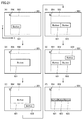
図1は、プログラマブル表示器の画面データの生成過程の一例を表した図である。
図1は、プログラマブル表示器の画面データの生成過程の一例を表した図である。
図1を参照して、情報処理装置は、作画機能を実行することにより、情報処理装置の表示画面に描画領域(作画領域)を設定する。描画領域は、第1の領域と、第2の領域とを含んでいる。典型的には、第1の領域はユーザ操作によって設定される。なお、典型的には、第1の領域の設定に伴い、描画領域における第1の領域以外の領域が第2の領域として自動的に確定する。
情報処理装置は、オブジェクトをドラッグし、かつ描画領域に当該オブジェクトをドロップするドラッグ・アンド・ドロップ操作を受け付ける。また、情報処理装置は、描画領域にドロップされたオブジェクトを描画する。
たとえば、状態(A)に示すように、情報処理装置は、オブジェクト#1のドラッグと、描画領域内の第1の領域へのオブジェクト#1のドロップとを受け付ける。この場合、情報処理装置は、オブジェクト#1がドロップされた領域が第1の領域であるため、状態(B)に示すように、オブジェクト#1の位置をドラッグされた位置から別の位置(たとえば、第1の領域の中央左端部)へと移動させる。
次に、状態(C)に示すように、情報処理装置は、オブジェクト#2のドラッグと、第1の領域へのオブジェクト#2のドロップとを受け付ける。この場合、情報処理装置は、状態(D)に示すように、オブジェクト#2の位置を移動させることにより、オブジェクト#1とオブジェクト#2とを第1の領域内において整列させる。たとえば、情報処理装置は、状態(D)に示すように、オブジェクト#1とオブジェクト#2とを、表示画面の横方向(図のX軸の方向)に並ぶように整列させる。
なお、情報処理装置は、状態(E)に示すように、オブジェクト#3のドラッグと、描画領域内の第2の領域へのオブジェクト#3のドロップとを受け付けた場合には、状態(F)に示すように、オブジェクト#3をドロップされた位置に配置する。つまり、譲歩処理装置は、第1の領域外ではオブジェクト#3の整列処理は実行しない。
情報処理装置は、オブジェクトの描画に基づき、プログラマブル表示器において表示させる画面の画面データを生成する。なお、当該生成されたデータは、典型的には情報処理装置からプログラマブル表示器に送信される。あるいは、当該生成されたデータは、USB(Universal Serial Bus)メモリ等の記憶媒体を用いて、プログラマブル表示器に格納される。
以上のように、情報処理装置は、描画領域内の第1の領域にオブジェクト#1が配置されている状態で、第1の領域にオブジェクト#2がドロップされると、オブジェクト#1とオブジェクト#2とを第1の領域内において整列させる。
上記の構成によれば、ユーザは、複数のオブジェクト#1,#2を整列させる操作が不要となる。それゆえ、プログラマブル表示器の画面データをユーザが作成する際の手間を削減可能となる。
§2 構成例
[実施の形態1]
<A.システム構成>
図2は、本実施の形態にかかるPLCシステム1000を示す模式図である。図2を参照して、PLCシステム1000は、複数のPLC1,2,3と、プログラマブル表示器4と、情報処理装置としてのPC(Personal Computer)5とを含む。
[実施の形態1]
<A.システム構成>
図2は、本実施の形態にかかるPLCシステム1000を示す模式図である。図2を参照して、PLCシステム1000は、複数のPLC1,2,3と、プログラマブル表示器4と、情報処理装置としてのPC(Personal Computer)5とを含む。
各PLC1~3は、典型的には、プログラムを実行する主体であるCPUユニット10と、CPUユニット10などへ電力を供給する電源ユニット12と、フィールドからの信号を遣り取りするIO(Input/Output)ユニット14とを含む。IOユニット14は、CPUユニット10とシステムバス11を介して接続されている。典型的には、IOユニット14は、フィールド機器である検出センサ6から入力信号を取得し、またCPUユニット10でのプログラムの実行結果に応じてフィールド機器であるリレー7を駆動する。
プログラマブル表示器4は、HMI(Human Machine Interface)環境におけるGUI(Graphical User Interface)としての役割を果たす。プログラマブル表示器4は、タッチパネルなどの操作部と液晶ディスプレイなどの表示部とCPUユニット10と通信する通信部と各部を制御する制御部とを備える。各PLC1~3は、プログラマブル表示器4の操作部による操作に応じて各種の設定の変更が可能であり、PLCの所定の情報をプログラマブル表示器4に表示させることが可能である。
PC5は、プログラマブル表示器4に接続される。PC5は、接続先のPLC1~3の運転状態や各種データの値などをモニタする機能を有している。PC5をサポート装置として機能させる場合、PC5は、PLC1~3で実行されるプログラムおよび設定情報を生成する。さらに、PC5は、ユーザによる実行可能プログラムの生成を支援するため、デバック機能やシミュレーション機能を有していてもよい。
PLC1~3は、たとえば、FINS(Factory Interface Netwrok Service)通信、HTTP(Hyper Text Transfer Protocol)通信、またはEIP(EtherNet/IP)通信のいずれかによりプログラマブル表示器4と通信する。
<B.ユーザインターフェイス>
(b1.作画画面)
図3は、プログラマブル表示器の画面データを作成するときに用いられるアプリケーションの実行によって、PC5のディスプレイに表示させる画面例を表した図である。
(b1.作画画面)
図3は、プログラマブル表示器の画面データを作成するときに用いられるアプリケーションの実行によって、PC5のディスプレイに表示させる画面例を表した図である。
図3を参照して、PC5の表示画面550は、ユーザが描画(作画)するための描画領域(作画領域)551を有する。描画領域551には、ユーザがレイアウト枠を設定することにより、レイアウト枠内の領域552(「第1の領域」の例)と、レイアウト枠外の領域553(「第2の領域」の例)とが形成される。
なお、図3では、点線で示した矩形がレイアウト枠を表している。以下では、レイアウト枠内の領域552を、「枠内領域552」と称し、レイアウト枠外の領域553を、「枠外領域553」とも称する。
描画領域551には、アイコン554が表示される。アイコン554に付与された機能については後述する。
表示画面550は、ツールボックスを有する。ツールボックスは、たとえば、ボタンのツール556と、ランプのツール557と、図形のツール558と、標準コントロールのツール559と、ゲージのツール560と、HMIコントロールのツール561と、カスタムのツール562と、コンベアのツール563と、タンクのツール564とを有する。
ボタンのツール556は、「セットボタン」を描画するためのツール5561と、「トグルボタン」を描画するためのツール5562と、「ボタン」(通常のボタン)を描画するためのツール5563と、「モーメンタリボタン」を描画するためのツール5564と、「リセットボタン」を描画するためのツール5565とを有する。なお、「セットボタン」、「トグルボタン」、「ボタン」、「モーメンタリボタン」、および「リセットボタン」の各々は、それぞれ、オブジェクトの一例である。
図3の例では、PC5がユーザによるドラッグ・アンド・ドロップ操作を行っている途中の状態を表している。具体的には、マウスでツール5563が選択されてドラック操作がなされ、領域551内にボタンのオブジェクト601をドラッグする直前の状態を表している。
詳細については後述するが、PC5では、枠内領域552では、オブジェクトの整列が実行される。つまり、レイアウト枠内ではレイアウト処理が実行される。以下では、まず、整列態様を設定するための設定画面を説明し、その後、整列の具体例を説明する。なお、設定画面は、ユーザ操作に基づき、表示画面550上に表示される。
(b2.設定画面)
図4は、設定画面での設定例を説明するための図である。
図4は、設定画面での設定例を説明するための図である。
図4を参照して、設定画面570では、ユーザは、整列の態様(スタイル)の設定を行うことができる。設定画面570は、配置方向を設定するためのアイコン571,572と、配置されたオブジェクトをラップさせる(折り返す)か否かを設定するためのラジオボタン573,574と、描画領域551に対応する領域551Aと、枠内領域552に対応する領域552Aと、位置に関するアイコン575,576,577と、ボタン578,579とを有する。
なお、アイコン571,572は、どちらかが選択状態となる。また、アイコン575,576,577は、いずれか1つが選択状態となる。
図4の設定画面570の例では、アイコン571が選択された状態を示している。この設定の場合、PC5は、枠内領域552に配置されたオブジェクトを横方向に整列する。また、図4の設定画面570の例では、アイコン575が選択された状態を示している。この設定の場合、PC5は、枠内領域552内の上端位置において、枠内領域552に配置されたオブジェクトを整列させる。
また、アイコン571が選択された状態において、アイコン576が選択されると、PC5は、枠内領域552内の中央位置において、枠内領域552に配置されたオブジェクトを横方向に整列させる。さらに、アイコン571が選択された状態において、アイコン577が選択されると、PC5は、枠内領域552内の下端位置において、枠内領域552に配置されたオブジェクトを横方向に整列させる。
PC5は、ユーザが設定内容を容易に確認できるように、3つのサンプル図形(図中の正方形、三角形、円)を用いて、選択された配置方向と選択された位置とを表示する。
ユーザによってボタン578が選択されると、PC5は、ユーザによって設定された設定内容を確定する。ユーザによってボタン579が選択されると、PC5は、今回の設定内容を廃棄する。
図5は、設定画面での他の設定例を説明するための図である。
図5を参照して、この設定画面570の例では、アイコン572が選択された状態を示している。この設定の場合、PC5は、枠内領域552に配置されたオブジェクトを縦方向に整列する。また、図5の設定画面570の例では、アイコン580が選択された状態を示している。この設定の場合、PC5は、枠内領域552内の左端部において、枠内領域552に配置されたオブジェクトを整列させる。
図5を参照して、この設定画面570の例では、アイコン572が選択された状態を示している。この設定の場合、PC5は、枠内領域552に配置されたオブジェクトを縦方向に整列する。また、図5の設定画面570の例では、アイコン580が選択された状態を示している。この設定の場合、PC5は、枠内領域552内の左端部において、枠内領域552に配置されたオブジェクトを整列させる。
また、アイコン572が選択された状態において、アイコン581が選択されると、PC5は、枠内領域552内の中央位置において、枠内領域552に配置されたオブジェクトを縦方向に整列させる。さらに、アイコン572が選択された状態において、アイコン582が選択されると、PC5は、枠内領域552内の右端部において、枠内領域552に配置されたオブジェクトを縦方向に整列させる。
以下では、設定画面570において各種の設定がなされた場合の整列態様について、具体例を挙げて説明する。特に、本実施の形態においては、「ボタン」のオブジェクトと、図形の一例としての「円」のオブジェクトを、ドラッグ・アンド・ドロップ操作によって、枠内領域552に描画する場合を例に挙げて説明する。
(b3.横方向に整列)
図6は、設定画面570においてアイコン571とアイコン576(図4参照)とが選択状態にある場合における、整列処理を説明するための状態遷移図である。つまり、図6は、横方向かつ中央位置での配置が選択されている場合の状態遷移図である。
図6は、設定画面570においてアイコン571とアイコン576(図4参照)とが選択状態にある場合における、整列処理を説明するための状態遷移図である。つまり、図6は、横方向かつ中央位置での配置が選択されている場合の状態遷移図である。
図6を参照して、状態(A)に示すように、PC5は、オブジェクト611のドラッグと、描画領域551内の枠内領域552へのオブジェクト611のドロップとを受け付ける。この場合、PC5は、オブジェクト611がドロップされた領域が枠内領域552であるため、状態(B)に示すように、オブジェクト611の位置をドラッグされた位置から枠内領域552の中央左端部へと移動させる。
次に、状態(C)に示すように、PC5は、オブジェクト612のドラッグと、枠内領域552へのオブジェクト612のドロップとを受け付ける。この場合、PC5は、状態(D)に示すように、オブジェクト612の位置を移動させることにより、オブジェクト611とオブジェクト612とを枠内領域552内の中央位置において左端側から横方向に整列させる。
次に、状態(E)に示すように、PC5は、オブジェクト613のドラッグと、枠内領域552へのオブジェクト613のドロップとを受け付ける。この場合、PC5は、状態(F)に示すように、オブジェクト613の位置を移動させることにより、オブジェクト611とオブジェクト612とオブジェクト613とを枠内領域552内の中央位置において左端側から横方向に整列させる。
図7は、設定画面570においてアイコン571とアイコン575(図4参照)とが選択状態にある場合における、オブジェクト611,612,613の整列態様を説明するための図である。つまり、図7は、横方向かつ上端位置での配置が選択されている場合の状態遷移図である。
図7を参照して、PC5は、枠内領域552へのオブジェクト613のドロップを受け付けと、オブジェクト613の位置を移動させることにより、オブジェクト611とオブジェクト612とオブジェクト613とを枠内領域552内の上端位置において左端側から横方向に整列させる。
図8は、設定画面570においてアイコン571とアイコン577(図4参照)とが選択状態にある場合における、オブジェクト611,612,613の整列態様を説明するための図である。図8は、横方向かつ下端位置での配置が選択されている場合の状態遷移図である。
図8を参照して、PC5は、枠内領域552へのオブジェクト613のドロップを受け付けと、オブジェクト613の位置を移動させることにより、オブジェクト611とオブジェクト612とオブジェクト613とを枠内領域552内の下端位置において左端側から横方向に整列させる。
(b4.縦方向に整列)
図9は、設定画面570においてアイコン572とアイコン581(図5参照)とが選択状態にある場合における、整列処理を説明するための遷移図である。つまり、図9は、縦方向かつ中央位置での配置が選択されている場合の状態遷移図である。
図9は、設定画面570においてアイコン572とアイコン581(図5参照)とが選択状態にある場合における、整列処理を説明するための遷移図である。つまり、図9は、縦方向かつ中央位置での配置が選択されている場合の状態遷移図である。
図9を参照して、状態(A)に示すように、PC5は、オブジェクト611のドラッグと、描画領域551内の枠内領域552へのオブジェクト611のドロップとを受け付ける。この場合、PC5は、オブジェクト611がドロップされた領域が枠内領域552であるため、状態(B)に示すように、オブジェクト611の位置をドラッグされた位置から枠内領域552の中央上端位置へと移動させる。
次に、状態(C)に示すように、PC5は、オブジェクト612のドラッグと、枠内領域552へのオブジェクト612のドロップとを受け付ける。この場合、PC5は、状態(D)に示すように、オブジェクト612の位置を移動させることにより、オブジェクト611とオブジェクト612とを枠内領域552内の中央位置において上端側から縦方向に整列させる。
次に、状態(E)に示すように、PC5は、オブジェクト613のドラッグと、枠内領域552へのオブジェクト613のドロップとを受け付ける。この場合、PC5は、状態(F)に示すように、オブジェクト613の位置を移動させることにより、オブジェクト611とオブジェクト612とオブジェクト613とを枠内領域552内の中央位置において上端側から縦方向に整列させる。
図10は、設定画面570においてアイコン572とアイコン580(図5参照)とが選択状態にある場合における、オブジェクト611,612,613の整列態様を説明するための図である。つまり、図10は、縦方向かつ左端位置での配置が選択されている場合の状態遷移図である。
図10を参照して、PC5は、枠内領域552へのオブジェクト613のドロップを受け付けと、オブジェクト613の位置を移動させることにより、オブジェクト611とオブジェクト612とオブジェクト613とを枠内領域552内の左端部において上端側から縦方向に整列させる。
図11は、設定画面570においてアイコン572とアイコン582(図5参照)とが選択状態にある場合における、オブジェクト611,612,613の整列態様を説明するための図である。つまり、図11は、縦方向かつ右端位置での配置が選択されている場合の状態遷移図である。
図11を参照して、PC5は、枠内領域552へのオブジェクト613のドロップを受け付けと、オブジェクト613の位置を移動させることにより、オブジェクト611とオブジェクト612とオブジェクト613とを枠内領域552内の右端部において上端側から縦方向に整列させる。
(b5.切替処理)
(1)設定画面570による切替処理
ユーザは、以下のような操作によって、横方向と縦方向との切替処理をPC5に実行させることができる。
(1)設定画面570による切替処理
ユーザは、以下のような操作によって、横方向と縦方向との切替処理をPC5に実行させることができる。
再び図6および図9を参照して、たとえば図6の状態(F)のように複数のオブジェクトを横方向に整列させた状態において、設定画面570を表示させてアイコン572を選択する操作を完了すると、PC5は、たとえば図9の状態(F)に示すように複数のオブジェクトを縦方向に整列させる。同様に、図9の状態(F)のように複数のオブジェクトを縦方向に整列させた状態において、設定画面570を表示させてアイコン571を選択する操作を完了すると、PC5は、たとえば図6の状態(F)に示すように複数のオブジェクトを横方向に整列させる。
また、ユーザは、枠内領域552に1以上のオブジェクトが配置されている状態において、アイコン575,576,577(図4参照)の選択がなされると、選択されたアイコンに対応付けられた位置に当該オブジェクトを移動させる。たとえば、アイコン576が選択された状態からアイコン575が選択された状態に切り替わると、PC5は、たとえば図6の状態(F)から図7の状態へと、オブジェクトの位置を変更する。
同様に、ユーザは、枠内領域552に1以上のオブジェクトが配置されている状態において、アイコン580,581,582(図5参照)の選択がなされると、選択されたアイコンに対応付けられた位置に当該オブジェクトを移動させる。たとえば、アイコン581が選択された状態からアイコン580が選択された状態に切り替わると、PC5は、たとえば図9の状態(F)から図10の状態へと、オブジェクトの位置を変更する。
このような構成によれば、ユーザは、描画の途中であっても、オブジェクトを整列方向および位置を変更可能となる。それゆえ、最初から描画をやり直す必要がなくなるため、ユーザの作業負担を減らすことが可能となる。
(2)アイコン544を用いた横方向と縦方向との切替処理
図12は、オブジェクトの整列方向の切替操作を説明するための図である。
図12は、オブジェクトの整列方向の切替操作を説明するための図である。
図12を参照して、状態(A)は、図6の状態(F)を示している。すなわち、図12の状態(A)では、オブジェクト611とオブジェクト612とオブジェクト613とが枠内領域552内の中央位置において左端側から横方向に整列している。
状態(B)は、図9の状態(F)を示している。すなわち、図12の状態(B)では、オブジェクト611とオブジェクト612とオブジェクト613とが枠内領域552内の中央位置において上端側から縦方向に整列している。
状態(A)においてユーザがマウス等でアイコン554をクリックすると、PC5は、枠内領域552のオブジェクト611,612,613の整列態様を、状態(A)から状態(B)へと切替える。つまり、PC5は、横並びから縦並びへと変更する。
同様に、状態(B)においてユーザがマウス等でアイコン554をクリックすると、PC5は、枠内領域552のオブジェクト611,612,613の整列態様を、状態(B)から状態(A)へと切替える。つまり、PC5は、縦並びから横並びへと変更する。
このように、ユーザは、アイコン554をクリックするだけで、横並びと縦並びとを逐次切換えることができる。このため、設定画面570を立ち上げるとともに配置方向に関するアイコン571,572(図4等参照)をクリックするといった一連の操作が不要となる。よって、画面デザイン変更に対するユーザの作業負担が軽減できる。
(b6.オブジェクトの折り返し処理)
オブジェクトの折り返し処理(ラップ処理)について、2つの例を挙げて説明する。
オブジェクトの折り返し処理(ラップ処理)について、2つの例を挙げて説明する。
(1)第1の例
図13は、オブジェクトの数が多くなったときに行われるオブジェクトの折り返し処理を説明するための図である。本例では、オブジェクトのサイズは、オブジェクトの種類に応じて固定されているものとする。
図13は、オブジェクトの数が多くなったときに行われるオブジェクトの折り返し処理を説明するための図である。本例では、オブジェクトのサイズは、オブジェクトの種類に応じて固定されているものとする。
図13を参照して、状態(A)では、オブジェクト611とオブジェクト612とオブジェクト613とが枠内領域552内の中央位置において左端側から横方向に整列している。
次に、状態(B)に示すように、PC5は、オブジェクト614のドラッグと、枠内領域552へのオブジェクト614のドロップとを受け付ける。この場合、PC5は、オブジェクト614のサイズ(この場合、横方向のサイズ)に基づき、4つのオブジェクト611,612,613,614が一行で収まるか否かを判断する。
PC5は、収まらないと判断すると、状態(C)に示すように、折り返し処理を実行する。具体的には、オブジェクト614の位置を枠内領域552の左端部であって、左端部のオブジェクト611の下側に移動させる。この場合、オブジェクト611,612,613,614からなるオブジェクト群が枠内領域552の中央位置に位置するように、オブジェクト611,612,613についても上方向(Y方向)に移動させる。
このように、PC5は、複数のオブジェクトを枠内領域552において整列させる場合、一行で表示できないときには、折り返し処理によって複数のオブジェクトを二行以上で整列させる。このような構成によれば、オブジェクトのサイズを変更することなく、オブジェクトを横方向に整列させることができる。
なお、上記においては、オブジェクトを横方向に整列させる構成を例に挙げて説明したが、これに限定されるものではない。縦方向に整列させる構成にも適用できる。具体的には、PC5は、複数のオブジェクトを枠内領域552において整列させる場合、一列で表示できないときには、折り返し処理によって複数のオブジェクトを二列以上で整列させる。
(2)第2の例
図14は、レイアウト枠を狭める操作がなされたとき(つまり、枠内領域552が狭まったとき)に行われるオブジェクトの折り返し処理を説明するための図である。
図14は、レイアウト枠を狭める操作がなされたとき(つまり、枠内領域552が狭まったとき)に行われるオブジェクトの折り返し処理を説明するための図である。
図14を参照して、状態(A)にて示すようにレイアウト枠が矢印590が示す方向に狭められた場合、オブジェクト613が枠内領域552に収まらなくなってしまう。この場合、PC5は、状態(B)に示すように、折り返し処理を行なう。具体的には、オブジェクト613の位置を枠内領域552の左端部であって、左端部のオブジェクト611の下側に移動させる。この場合、オブジェクト611,612,613からなるオブジェクト群が枠内領域552の中央位置に位置するように、オブジェクト611,612についても上方向(Y方向)に移動させる。
このように、PC5は、複数のオブジェクトを枠内領域552において整列させる場合、一行で表示できないときには、折り返し処理によって複数のオブジェクトを二行以上で整列させる。
(b7.オブジェクトの縮小処理)
オブジェクトの縮小処理について、2つの例を挙げて説明する。
オブジェクトの縮小処理について、2つの例を挙げて説明する。
(1)第1の例
図15は、オブジェクトの数が多くなったときに行われるオブジェクトの縮小処理を説明するための図である。
図15は、オブジェクトの数が多くなったときに行われるオブジェクトの縮小処理を説明するための図である。
図15を参照して、状態(A)に示すように、オブジェクト611,612,613が横方向に整列した状態において、オブジェクト614のドラッグと、枠内領域552へのオブジェクト614のドロップとを受け付ける。この場合、PC5は、オブジェクト614のサイズ(この場合、横方向のサイズ)に基づき、4つのオブジェクト611,612,613,614が一行で収まるか否かを判断する。
PC5は、収まらないと判断すると、状態(B)に示すように、全てのオブジェクト611,612,613,614のサイズを縮小する処理を実行する。典型的には、オブジェクト611,612,613,614を一行で整列させた状態で枠内領域552に収まるように、オブジェクト611,612,613,614を縮小する。
このように、PC5は、複数のオブジェクトを枠内領域552において整列させる場合、一行で表示するために、複数のオブジェクトの各々のサイズを小さくする。このような構成によれば、オブジェクトを横方向に一行で整列させることができる。これによれば、画面デザイン変更に対するユーザの作業負担が軽減できる。
なお、上記においては、オブジェクトを横方向に整列させる構成を例に挙げて説明したが、これに限定されるものではない。縦方向に整列させる構成にも適用できる。具体的には、PC5は、複数のオブジェクトを枠内領域552において整列させる場合、一列で表示するために、複数のオブジェクトの各々のサイズを小さくする。
(2)第2の例
図16は、レイアウト枠を狭める操作がなされたとき(つまり、枠内領域552が狭まったとき)に行われるオブジェクトの縮小処理を説明するための図である。
図16は、レイアウト枠を狭める操作がなされたとき(つまり、枠内領域552が狭まったとき)に行われるオブジェクトの縮小処理を説明するための図である。
図16を参照して、状態(A)にて示すようにレイアウト枠が矢印590が示す方向に狭められた場合、オブジェクト613が枠内領域552に収まらなくなってしまう。この場合、PC5は、状態(B)に示すように、各オブジェクトの縮小処理を行なう。典型的には、オブジェクト611,612,613を一行で整列させた状態で、狭められた枠内領域552に収まるように、オブジェクト611,612,613を縮小する。
このように、PC5は、複数のオブジェクトが一行で配置されている状態において、枠内領域552のサイズが横方向に縮小されることにより、複数のオブジェクトが一行で配置できないと判断した場合、複数のオブジェクトの各々のサイズを小さくすることにより複数のオブジェクトを一行で配置する。このような構成によれば、ユーザは、枠内領域552を横方向に狭める操作を行った場合であっても、一行に収めるためにオブジェクトの位置およびサイズを変更する操作を行う必要がなくなる。このように、画面デザイン変更に対するユーザの作業負担が軽減できる。
なお、上記においては、オブジェクトを横方向に整列させる構成を例に挙げて説明したが、これに限定されるものではない。縦方向に整列させる構成にも適用できる。具体的には、PC5は、複数のオブジェクトが一列で配置されている状態において、枠内領域552のサイズが縦方向に縮小されることにより、複数のオブジェクトが一列で配置できないと判断した場合、複数のオブジェクトの各々のサイズを小さくすることにより複数のオブジェクトを一列で配置する。
(b8.オブジェクトの拡大処理)
オブジェクトの拡大処理について説明する。
オブジェクトの拡大処理について説明する。
図17は、レイアウト枠を拡大する操作がなされたとき(つまり、枠内領域552が広がったとき)に行われるオブジェクトの拡大処理を説明するための図である。
状態(A)に示すように、オブジェクト611,612,613が横方向に一行で整列している状態において、状態(B)に示すように、レイアウト枠が矢印591が示す方向に拡大された場合、PC5は、オブジェクトの拡大処理を行なう。典型的には、PC5は、枠内領域552の幅に対する3つのオブジェクト611~613の横幅の合計の比率を一定に保つように、オブジェクト611~613を同じ比率で縦および横方向に拡大する。
このように、PC5は、複数のオブジェクトが一行で配置されている状態において、枠内領域552のサイズが少なくとも行方向に拡大された場合、当該拡大後の枠内領域552のサイズに基づき、複数のオブジェクトの各々のサイズを大きくする。このような構成によれば、ユーザは、枠内領域552を横方向に拡大する操作を行った場合、各オブジェクトの位置およびサイズを変更する操作を行う必要がなくなる。このように、画面デザイン変更に対するユーザの作業負担が軽減できる。
<C.機能的構成>
図18は、PC5の機能的構成を説明するためのブロック図である。
図18は、PC5の機能的構成を説明するためのブロック図である。
図18を参照して、PC5は、入力装置701と、表示装置702と、制御部703と、通信IF部704とを備える。
入力装置701は、キーボード510と、マウス512とを備える。
制御部703は、PC5の全体的な動作を制御する。制御部703は、作画エディタとしても機能する。制御部703は、操作受付部731と、表示制御部732と、画面データ生成部733と、領域サイズ変更部734と、オブジェクトサイズ変更部735とを備える。
制御部703は、PC5の全体的な動作を制御する。制御部703は、作画エディタとしても機能する。制御部703は、操作受付部731と、表示制御部732と、画面データ生成部733と、領域サイズ変更部734と、オブジェクトサイズ変更部735とを備える。
表示制御部732は、表示装置702に、PC5の状態に即した各種の画面を表示させる。表示制御部732は、ユーザ操作に基づき、オブジェクトの整列態様を設定するための設定画面570(図4等)を表示装置702の表示画面550(図3参照)に表示させる。また、表示制御部は、表示画面550内(典型的には、描画領域551)にアイコン554(図3参照)をさらに表示する。
表示制御部732は、描画部7320を備える。描画部7320は、整列処理部7321を備える。
操作受付部731は、入力装置701を介した各種のユーザ操作を受け付ける。たとえば、操作受付部731は、オブジェクトをドラッグし、かつPC5の表示画面550内に設けられた描画領域551にオブジェクトをドロップするドラッグ・アンド・ドロップ操作を受け付ける。また、操作受付部731は、レイアウト枠(換言すれば、枠内領域552)のサイズを変更(拡大または縮小)する操作を受け付ける。さらに、操作受付部731は、レイアウト枠(換言すれば、枠内領域552)の位置を変更する操作を受け付ける。
操作受付部731が描画領域551にオブジェクトをドロップするドラッグ・アンド・ドロップ操作を受け付けると、描画部7320は、描画領域551において、ドロップされたオブジェクトの描画を行う。整列処理部7321は、設定画面における設定に基づき、枠内領域552にドロップされたオブジェクトの整列を行う。
描画部7320は、たとえば、枠内領域552に第1のオブジェクト(たとえば、オブジェクト611)が配置されている状態で、枠内領域552に第2のオブジェクト(たとえば、オブジェクト612)がドロップされると、第1のオブジェクトと第2のオブジェクトとを枠内領域552内において整列させる。一方、描画部7320は、枠外領域553に第3のオブジェクトがドロップされると、当該ドロップされた位置に第3のオブジェクトを配置する。
画面データ生成部733は、オブジェクトの描画に基づき、プログラマブル表示器4において表示させる画面の画面データを生成する。詳しくは、画面データ生成部733は、描画部7320から描画データを受け取り、表示器用画面データを生成する。画面データ生成部733は、生成された画面データを通信IF部704に送る。
通信IF部704は、画面データをプログラマブル表示器4に送信する。
以下、描画部7320のさらなる処理について説明する。なお、以下では、第1のオブジェクトの一例として、オブジェクト611を挙げ、第2のオブジェクトの一例として、オブジェクト612を挙げて説明する。
以下、描画部7320のさらなる処理について説明する。なお、以下では、第1のオブジェクトの一例として、オブジェクト611を挙げ、第2のオブジェクトの一例として、オブジェクト612を挙げて説明する。
(1)図6を再び参照して、描画部7320は、設定画面570にてアイコン571が選択されている場合(第1の方向設定がなされている場合)には、オブジェクト612がドロップされると、オブジェクト611とオブジェクト612とを、枠内領域552の横方向に整列させる。
また、図9を再び参照して、描画部7320は、設定画面570にてアイコン572が選択されている場合(第2の方向設定がなされている場合)には、オブジェクト612がドロップされると、オブジェクト611とオブジェクト612とを、枠内領域552の縦方向に整列させる。
(2)図12を再び参照して、描画部7320は、オブジェクト611とオブジェクト612とが横方向(X軸方向)および縦方向(Y軸方向)のうちの一方向に整列している状態で、アイコン544がクリックされると、オブジェクト611とオブジェクト612とを横方向および縦方向のうちの他方向に整列させる。
(3)描画部7320は、図4に示すように設定画面570にてアイコン571が選択されている場合(第1の方向設定がなされている場合)、以下の処理を行なう。
描画部7320は、設定画面570にてアイコン575(図4参照)が選択されているとき(第1の位置設定がさらになされているとき)には、枠内領域552内の上端位置にて、オブジェクト611とオブジェクト612とを横方向に整列させる(図7参照)。
描画部7320は、設定画面570にてアイコン576が選択されているとき(第2の位置設定がさらになされているとき)には、枠内領域552内の中央位置にて、オブジェクト611とオブジェクト612とを横方向に整列させる(図6参照)。
描画部7320は、設定画面570にてアイコン577が選択されているとき(第3の位置設定がさらになされているとき)には、枠内領域552内の下端位置にて、オブジェクト611とオブジェクト612とを横方向に整列させる(図8参照)。
(4)描画部7320は、図5に示すように設定画面570にてアイコン572が選択されている場合(第1の方向設定がなされている場合)、以下の処理を行なう。
描画部7320は、設定画面570にてアイコン580(図5参照)が選択されているとき(第4の位置設定がさらになされているとき)には、枠内領域552内の左端位置にて、オブジェクト611とオブジェクト612とを縦方向に整列させる(図10参照)。
描画部7320は、設定画面570にてアイコン581が選択されているとき(第5の位置設定がさらになされているとき)には、枠内領域552内の中央位置にて、オブジェクト611とオブジェクト612とを縦方向に整列させる(図9参照)。
描画部7320は、設定画面570にてアイコン582が選択されているとき(第6の位置設定がさらになされているとき)には、枠内領域552内の右端位置にて、オブジェクト611とオブジェクト612とを縦方向に整列させる(図11参照)。
(5)図13および図14を再び参照して、描画部7320は、オブジェクト611とオブジェクト612とを含む複数のオブジェクトを枠内領域552において整列させる場合、一行または一列で表示できないときには、折り返し処理によって当該複数のオブジェクトを二行以上または二列以上で整列する。
(6)図15および図16を再び参照して、描画部7320は、オブジェクト611とオブジェクト612とを含む複数のオブジェクトを枠内領域552において整列させる場合、一行または一列で表示するために、当該複数のオブジェクトの各々のサイズを小さくする。
(7)ユーザ操作に基づき、領域サイズ変更部734によって枠内領域552のサイズが変更された場合、描画部7320は以下の処理を行なう。
図16を再び参照して、描画部7320は、複数のオブジェクトが一行または一列で配置されている状態において、枠内領域552のサイズが縮小されることにより、当該複数のオブジェクトが一行または一列で配置できないと判断した場合、当該複数のオブジェクトの各々のサイズを小さくすることにより当該複数のオブジェクトを一行または一列で配置する。
(8)図17を再び参照して、描画部7320は、複数のオブジェクトが一行または一列で配置されている状態において、枠内領域552のサイズが行方向または列方向に拡大された場合、当該拡大後の枠内領域552のサイズに基づき、当該複数のオブジェクトの各々のサイズを大きくする。
<D.制御構造>
説明の便宜上、以下では、描画領域551のうち枠内領域552にオブジェクトがドロップされたときの処理に着目して、制御構造を説明する。図19は、PC5で実行される処理の流れを説明するためのフロー図である。
説明の便宜上、以下では、描画領域551のうち枠内領域552にオブジェクトがドロップされたときの処理に着目して、制御構造を説明する。図19は、PC5で実行される処理の流れを説明するためのフロー図である。
図19を参照して、ステップS1において、PC5は、予め定められた変数iの値を1に設定する。ステップS2において、PC5は、枠内領域552内に1番目のオブジェクトをドロップする操作を受け付ける。ステップS3において、PC5は、設定画面570での設定に応じて、1番目のオブジェクトを枠内領域552に配置する(図6の状態(B)等参照)。
ステップS4において、PC5は、枠内領域552内にi+1番目のオブジェクトをドロップする操作を受け付けたか否かを判断する。PC5は、操作を受け付けたと判断した場合(ステップS4においてYES)、ステップS5において、設定画面での設定に応じて1番目からi+1番目までのオブジェクトを枠内領域552内に整列配置する。PC5は、操作を受け付けていないと判断した場合(ステップS4においてNO)、処理をステップS7に進める。
ステップS6にて、PC5は、変数iの値をインクリメントする。すなわち、PC5は、変数iの値を1だけ増加させる。ステップS7において、PC5は、プログラマブル表示器用の画面データの生成指示(ユーザ指示)を受け付けた否かを判断する。
PC5は、生成指示を受け付けたと判断した場合(ステップS7においてYES)、ステップS8において、描画領域551内のオブジェクトに基づいた画面データ(表示器用の画面データ)を生成する。PC5は、生成指示を受け付けていないと判断した場合(ステップS7においてNO)、処理をステップS4に戻す。
<E.ハードウェア構成>
図20は、PC5のハードウェア構成を示す模式図である。図20を参照して、PC5は、OSを含む各種プログラムを実行するCPU502と、BIOSや各種データを格納するROM(Read Only Memory)504と、CPU502でのプログラムの実行に必要なデータを格納するための作業領域を提供するメモリRAM506と、CPU502で実行されるプログラムなどを不揮発的に格納するハードディスク(HDD)508とを含む。
図20は、PC5のハードウェア構成を示す模式図である。図20を参照して、PC5は、OSを含む各種プログラムを実行するCPU502と、BIOSや各種データを格納するROM(Read Only Memory)504と、CPU502でのプログラムの実行に必要なデータを格納するための作業領域を提供するメモリRAM506と、CPU502で実行されるプログラムなどを不揮発的に格納するハードディスク(HDD)508とを含む。
PC5は、さらに、ユーザからの操作を受け付けるキーボード510およびマウス512と、情報をユーザに提示するためのモニタ514とを含む。さらに、PC5は、プログラマブル表示器4などと通信するための通信インターフェイス(IF)518を含む。PC5は、通信IF518によってプログラマブル表示器4と通信可能に接続される。
[実施の形態2]
本実施の形態では、オブジェクトを枠内領域552にドロップするたびに、オブジェクトのサイズを変更する構成について説明する。なお、本実施の形態では、実施の形態1との相違点のみを説明し、実施の形態1との共通点については説明を繰り返さない。
[実施の形態2]
本実施の形態では、オブジェクトを枠内領域552にドロップするたびに、オブジェクトのサイズを変更する構成について説明する。なお、本実施の形態では、実施の形態1との相違点のみを説明し、実施の形態1との共通点については説明を繰り返さない。
図21は、整列処理を説明するための状態遷移図である。なお、本例では、設定画面570(図4参照)において、アイコン571とアイコン576とが選択状態にあるものとする。つまり、横方向かつ中央位置での配置が選択されているものとする。
図21を参照して、状態(A)に示すように、PC5は、オブジェクト621のドラッグと、枠内領域552へのオブジェクト621のドロップとを受け付ける。この場合、PC5は、オブジェクト621がドロップされた領域が枠内領域552であるため、状態(B)に示すように、オブジェクト621のサイズを拡大するとともに、オブジェクト621の位置をドラッグされた位置から枠内領域552の中央位置へと移動させる。詳しくは、PC5は、枠内領域552の横幅とオブジェクト621との横幅とが一致するように、オブジェクト621を縦方向と横方向とにおいて同倍率で拡大する。
次に、状態(C)に示すように、PC5は、オブジェクト622のドラッグと、枠内領域552へのオブジェクト622のドロップとを受け付ける。この場合、PC5は、状態(D)に示すように、オブジェクト621とオブジェクト622とを枠内領域552内の中央位置において左端側から順に横方向に整列させる。
詳しくは、PC5は、オブジェクト621とオブジェクト622とのデフォルトサイズからの拡縮率が同じとなるように、オブジェクト621,622のサイズを変更する。さらに詳しくは、PC5は、枠内領域552の横幅と、2つのオブジェクト621,622の横幅の合計とが一致するように、オブジェクト621,622のサイズを拡大または縮小する。なお、オブジェクト621,622は、同種のオブジェクトであるため、状態(D)に示すように、サイズは同一となっている。
次に、状態(E)に示すように、PC5は、オブジェクト623のドラッグと、枠内領域552へのオブジェクト623のドロップとを受け付ける。この場合、PC5は、状態(F)に示すように、オブジェクト621とオブジェクト622とオブジェクト623とを枠内領域552内の中央位置において左端側から順に横方向に整列させる。
詳しくは、PC5は、オブジェクト621とオブジェクト622とオブジェクト623とのデフォルトサイズからの拡縮率が同じとなるように、オブジェクト621,622,623のサイズを変更する。さらに詳しくは、PC5は、枠内領域552の横幅と、3つのオブジェクト621,622,623の横幅の合計とが一致するように、オブジェクト621,622,623のサイズを拡大または縮小する。
このように、PC5(詳しくは、描画部7320)は、枠内領域552のサイズと、枠内領域552にドロップされるオブジェクトの数とに応じて各オブジェクトのサイズを変更する構成である。詳しくは、PC5は、各オブジェクトのサイズが、枠内領域552のサイズを枠内領域552にドロップされたオブジェクトの数で均等分割したサイズになるように、各オブジェクトのサイズを自動変更する。つまり、PC5は、レイアウト枠へのフィッティング処理を実行する。この構成によれば、ユーザは、各オブジェクトのサイズを変更する操作を行うことなく、複数のオブジェクトが整列した画面データを得ることができる。
なお、オブジェクトの数が増加し、デフォルトのサイズ以下に縮小しないと枠内領域552に一列で収まらない場合には、折り返し処理を行なうように、描画部7320を構成してもよい。
また、上記においては、横方向にオブジェクトを並べる例を挙げているが、縦方向にオブジェクトを並べる場合にも上記の処理を適用できる。上記のような処理を行なうか否かを設定できるように、設定画面570を構成しておけばよい。
<変形例>
図22は、整列処理の他の例を説明するための状態遷移図である。なお、本例でも、設定画面570(図4参照)において、アイコン571とアイコン576とが選択状態にあるものとする。つまり、横方向かつ中央位置での配置が選択されているものとする。
図22は、整列処理の他の例を説明するための状態遷移図である。なお、本例でも、設定画面570(図4参照)において、アイコン571とアイコン576とが選択状態にあるものとする。つまり、横方向かつ中央位置での配置が選択されているものとする。
図22を参照して、状態(A)に示すように、PC5は、オブジェクト621のドラッグと、枠内領域552へのオブジェクト621のドロップとを受け付ける。この場合、PC5は、オブジェクト621がドロップされた領域が枠内領域552であるため、状態(B)に示すように、オブジェクト621のサイズを拡大するとともに、オブジェクト621の位置をドラッグされた位置から枠内領域552の中央位置へと移動させる。詳しくは、PC5は、枠内領域552の横幅および高さとオブジェクト621の横幅および高さとが一致するように、オブジェクト621を縦方向と横方向とにおいて拡大する。
次に、状態(C)に示すように、PC5は、オブジェクト622のドラッグと、枠内領域552へのオブジェクト622のドロップとを受け付ける。この場合、PC5は、状態(D)に示すように、オブジェクト621とオブジェクト622とを枠内領域552内の中央位置において左端側から順に横方向に整列させる。
詳しくは、PC5は、オブジェクト621とオブジェクト622とのデフォルトサイズからの拡縮率が同じとなるように、オブジェクト621,622のサイズを変更する。さらに詳しくは、PC5は、枠内領域552の横幅と、2つのオブジェクト621,622の横幅の合計とが一致するように、オブジェクト621,622の横方向のサイズを拡大または縮小する。また、PC5は、オブジェクト622の縦方向のサイズを枠内領域552の高さと一致させる。なお、オブジェクト621,622は、同種のオブジェクトであるため、状態(D)に示すように、サイズは同一となっている。
次に、状態(E)に示すように、PC5は、オブジェクト623のドラッグと、枠内領域552へのオブジェクト623のドロップとを受け付ける。この場合、PC5は、状態(F)に示すように、オブジェクト621とオブジェクト622とオブジェクト623とを枠内領域552内の中央位置において左端側から順に横方向に整列させる。
詳しくは、PC5は、オブジェクト621とオブジェクト622とオブジェクト623とのデフォルトサイズからの拡縮率が同じとなるように、オブジェクト621,622,623のサイズを変更する。さらに詳しくは、PC5は、枠内領域552の横幅と、3つのオブジェクト621,622,623の横幅の合計とが一致するように、オブジェクト621,622,623のサイズを拡大または縮小する。また、PC5は、オブジェクト623の縦方向のサイズを枠内領域552の高さと一致させる。なお、オブジェクト621,622,623は、同種のオブジェクトであるため、状態(F)に示すように、サイズは同一となっている。
このような構成によれば、枠内領域552を1以上のオブジェクトで満たすことが可能となるとともに、複数のオブジェクトを整列させることが可能となる。
[実施の形態3]
本実施の形態では、オブジェクトの配置関するテンプレートを生成し、当該生成されたテンプレートを活用して新たな画面データを生成する構成について説明する。なお、本実施の形態では、実施の形態1との相違点のみを説明し、実施の形態1との共通点については説明を繰り返さない。なお、実施の形態1のPC5と区別するために、説明の便宜上、本実施の形態におけるPCを「PC5A」と称する。
[実施の形態3]
本実施の形態では、オブジェクトの配置関するテンプレートを生成し、当該生成されたテンプレートを活用して新たな画面データを生成する構成について説明する。なお、本実施の形態では、実施の形態1との相違点のみを説明し、実施の形態1との共通点については説明を繰り返さない。なお、実施の形態1のPC5と区別するために、説明の便宜上、本実施の形態におけるPCを「PC5A」と称する。
<A.処理の概要>
PC5Aは、ユーザによって選択された範囲内のオブジェクトの位置およびサイズ(選択範囲に対する相対的な位置、割合的なサイズ)、種類をテンプレートとして情報保存できる仕組みを有する。
PC5Aは、ユーザによって選択された範囲内のオブジェクトの位置およびサイズ(選択範囲に対する相対的な位置、割合的なサイズ)、種類をテンプレートとして情報保存できる仕組みを有する。
枠内領域552の設定として、上記テンプレート情報を読み込む仕組みを用意する。PC5Aは、テンプレート情報が読み出されると、読み出されたテンプレートの枠内領域552内に、テンプレートで定義されている種類のオブジェクトを、テンプレートで定義されている位置、サイズで、自動配置および整列させる。
PC5Aは、上記テンプレート情報を読み込んだ枠内領域552内に、オブジェクトをドロップさせると、当該オブジェクトの種類がテンプレートで定義されていれば、指定の位置に指定のサイズで当該オブジェクトを配置する。
なお、PC5Aは、枠内領域552のサイズがユーザ操作によって変更されると、枠内領域552内に配置済みの各オブジェクトの位置関係を維持したまま、一定の割合で各オブジェクトのサイズを自動変更する。
<B.ユーザインターフェイス>
テンプレートの作成および利用の局面におけるユーザインターフェイスの例について、以下説明する。
テンプレートの作成および利用の局面におけるユーザインターフェイスの例について、以下説明する。
図23は、PC5Aの表示画面550を表した図である。図23を参照して、ユーザは、描画領域551において範囲801を指定する。範囲801が指定された状態で、マウス等のクリック操作によってコンテキストメニュー802内のレイアウトテンプレート保存の項目803が選択されると、範囲801に含まれるオブジェクトの配置およびサイズがテンプレートとして保存される。
なお、典型的には、テンプレートは他のテンプレートと識別可能なように名称が付され状態で保存される。テンプレートの保存先はファイルの保存場所でもよい。ツールにライブラリ一覧のようなリストを用意しておき、そこにテンプレートが保存されるような仕組みであってもよい。
図24は、図23の後にPC5Aで表示される表示画面550を表した図である。図24を参照して、ユーザが枠内領域552を設定する。その後、ユーザは、マウス等のクリック操作によってコンテキストメニュー804内において、レイアウトテンプレート適用の項目805を選択する。さらに、典型的には、ユーザは、項目805を選択した後、テンプレートを選択する。なお、ツールのライブラリ一覧を表示し、その中から適用するテンプレートを選択する構成であってもよい。
図25は、図24の後にPC5Aで表示される表示画面550を表した図である。図25を参照して、PC5Aは、枠内領域552に、選択されたテンプレートに基づいた要素領域5521,5522,5523,5524,5525,5526を設定し、かつ要素領域(具体的には、要素領域のレイアウト枠)を表示する。具体的には、適用したテンプレートに含まれるオブジェクトの位置と相対サイズとに基づいて枠内領域552をさらに複数の領域に区分けする。
さらに、PC5Aは、各要素領域5521~5526に配置可能なオブジェクトの種類を表示する。たとえば、図25の例では、オブジェクトの種類として、「Label」,「DataDisplay」,「Button」が表示されている。
図26は、図25の後にPC5Aで表示される表示画面550を表した図である。図26を参照して、ユーザは、テンプレートが適用された状態(図25の状態)で、所望するオブジェクト(図26の場合には「ボタン」)をドラッグし、かつ枠内領域552の任意の位置に当該オブジェクト631をドロップする操作を行う。
図27は、図26の後にPC5Aで表示される表示画面550を表した図である。図27を参照して、オブジェクト631が枠内領域552にドロップされると、オブジェクト631の種類に合致した要素領域にオブジェクトが配置される。
図27の例の場合、オブジェクト631がボタンであるため、ボタンの要素領域にオブジェクトが配置される。詳しくは、本例ではオブジェクトを左から順に整列させる設定となっており、かつ、要素領域5523,5526の2つにオブジェクトが配置されていないため、PC5Aは、オブジェクト631を左側の要素領域5523に配置する。さらに詳しくは、PC5Aは、オブジェクト631が要素領域5523を満たすように(フィットするように)、オブジェクト631を拡大(あるいは縮小)する。
<C.機能的構成>
図28は、PC5Aの機能的構成を説明するためのブロック図である。
図28は、PC5Aの機能的構成を説明するためのブロック図である。
図28を参照して、PC5Aは、入力装置701と、表示装置702と、制御部703Aと、通信IF部704と、テンプレート記憶部705とを備える。
制御部703Aは、PC5Aの全体的な動作を制御する。制御部703Aは、テンプレート生成部736とテンプレート読出部737とを備える点において、実施の形態1の制御部703(図18参照)と異なる。したがって、以下では、テンプレート生成部736およびテンプレート読出部737における処理に着目した説明をし、実施の形態1で説明した内容については繰り返さない。
操作受付部731は、枠内領域552が設定されていない状態で描画領域551において範囲を指定する入力を受け付ける(図23参照)。
テンプレート生成部736は、指定された範囲に含まれる1以上のオブジェクトの配置およびサイズをテンプレートとして生成する。テンプレート生成部736は、生成されたテンプレートをテンプレート記憶部705に保存する。
枠内領域552を設定するためのユーザ操作を操作受付部731が受け付けた場合、描画部7320は、描画領域551内に枠内領域552を描画する。次いで、コンテキストメニューを表示し、かつレイアウトテンプレート適用の項目を選択するユーザ操作を操作受付部731が受け付けた場合(図24参照)、PC5Aは、枠内領域552に選択されたテンプレートを適用する。具体的には、テンプレート読出部737がテンプレート記憶部705から選択されたテンプレートを読み出す。テンプレート読出部737は、読み出したテンプレートを描画部7320に送る。
描画部7320は、テンプレートに基づき、当該テンプレートの要素領域を、各要素領域の種別名とともに、描画領域551の枠内領域552に表示する(図25参照)。
要素領域が表示された状態で、操作受付部731がオブジェクトのドラッグ・アンド・ドロップ操作を受け付けると(図26参照)、描画部7320は、当該オブジェクトの種別と同じ種別の要素領域に当該オブジェクトをフィッティングさせる(図27参照)。
<D.利点>
プログラマブル表示器の画面デザインにおいて、いくつかのオブジェクトを組み合わせて、ある情報をわかりやすく表示したり設定したりできるようにユーザがアプリを作成する。このように組み合わせたオブジェクトは、使い勝手がよく汎用的であれば、他のプログラマブル表示器で利用する画面の一部にも流用される。しかしながら、同じオブジェクトの組み合わせであっても、見た目(デザイン)は、使用するプログラマブル表示器、あるいはユーザの好みに応じて変更することが多い。
プログラマブル表示器の画面デザインにおいて、いくつかのオブジェクトを組み合わせて、ある情報をわかりやすく表示したり設定したりできるようにユーザがアプリを作成する。このように組み合わせたオブジェクトは、使い勝手がよく汎用的であれば、他のプログラマブル表示器で利用する画面の一部にも流用される。しかしながら、同じオブジェクトの組み合わせであっても、見た目(デザイン)は、使用するプログラマブル表示器、あるいはユーザの好みに応じて変更することが多い。
PC5Aでは、このような用途でオブジェクトの種類、サイズ位置関係を、保存および再現できる仕組みを提供できる。それゆえ、PC5Aによれば、データ流用性を向上させ、ユーザの画面デザインにかかる工数を削減する効果がある。
[実施の形態4]
本実施の形態では、オブジェクトにアドレスまたは変数を設定できる構成について説明する。なお、本実施の形態では、実施の形態1との相違点のみを説明し、実施の形態1との共通点については説明を繰り返さない。なお、実施の形態1のPC5等と区別するために、説明の便宜上、本実施の形態におけるPCを「PC5B」と称する。
[実施の形態4]
本実施の形態では、オブジェクトにアドレスまたは変数を設定できる構成について説明する。なお、本実施の形態では、実施の形態1との相違点のみを説明し、実施の形態1との共通点については説明を繰り返さない。なお、実施の形態1のPC5等と区別するために、説明の便宜上、本実施の形態におけるPCを「PC5B」と称する。
<A.処理の概要>
枠内領域552の設定として、アドレスおよび/または変数を設定できる仕組みを用意する。枠内領域552内にオブジェクトがドロップされると、当該オブジェクトがアドレスおよび/または変数の値を表示したり、入力した値をアドレスおよび/または変数に書き込んだりする機能を持っているものであれば、PC5Bは、枠内領域552に設定したアドレスおよび/または変数を自動的に当該オブジェクトの設定に割り付ける。このとき、PC5Bは、オブジェクトが枠内領域552にドロップされるごとに、アドレスの場合には自動的にアドレスのインクリメント、変数の場合には変数名の末尾の数字を自動インクリメント、変数が配列変数の場合には要素番号を自動インクリメントすることにより、インクリメント後の値をオブジェクトの設定に割り付ける。
枠内領域552の設定として、アドレスおよび/または変数を設定できる仕組みを用意する。枠内領域552内にオブジェクトがドロップされると、当該オブジェクトがアドレスおよび/または変数の値を表示したり、入力した値をアドレスおよび/または変数に書き込んだりする機能を持っているものであれば、PC5Bは、枠内領域552に設定したアドレスおよび/または変数を自動的に当該オブジェクトの設定に割り付ける。このとき、PC5Bは、オブジェクトが枠内領域552にドロップされるごとに、アドレスの場合には自動的にアドレスのインクリメント、変数の場合には変数名の末尾の数字を自動インクリメント、変数が配列変数の場合には要素番号を自動インクリメントすることにより、インクリメント後の値をオブジェクトの設定に割り付ける。
<B.ユーザインターフェイス>
アドレスを設定する局面におけるユーザインターフェイスの例について、以下説明する。
アドレスを設定する局面におけるユーザインターフェイスの例について、以下説明する。
図29は、PC5Bの表示画面550を表した図である。図29を参照して、PC5Bは、枠内領域552の設定項目として、「割当アドレス」の項目565を表示する。
図30は、図29の後にPC5Bで表示される表示画面550の描画領域551を表した図である。図30を参照して、オブジェクト641が枠内領域552にドロップされると、図29で示さている割当アドレス“W0.0”がオブジェクト641に設定される。この設定に伴い、「割当アドレス」の項目565に示された値がインクリメントされ、“W0.1”となる。この状態で、ユーザが次のオブジェクト642を枠内領域552にドロップすると、割当アドレス“W0.1”がオブジェクト641に設定される。
<C.機能的構成>
図31は、PC5Bの機能的構成を説明するためのブロック図である。
図31は、PC5Bの機能的構成を説明するためのブロック図である。
図31を参照して、PC5Bは、入力装置701と、表示装置702と、制御部703Bと、通信IF部704とを備える。
制御部703Aは、PC5Bの全体的な動作を制御する。制御部703Bは、設定部738を備える点において、実施の形態1の制御部703(図18参照)と異なる。したがって、以下では、設定部738における処理に着目した説明をし、実施の形態1で説明した内容については繰り返さない。
設定部738は、アドレス設定部7381と、変数設定部7382とを備える。
アドレス設定部7381は、枠内領域552にドロップされたオブジェクトに対して、アドレスを割り当てる。また、アドレス設定部7381は、当該割り当て後に、アドレスのインクリメントを行う。アドレス設定部7381は、枠内領域552に次にドロップされるオブジェクトに対して、当該インクリメント後のアドレスを割り当てる。
アドレス設定部7381は、枠内領域552にドロップされたオブジェクトに対して、アドレスを割り当てる。また、アドレス設定部7381は、当該割り当て後に、アドレスのインクリメントを行う。アドレス設定部7381は、枠内領域552に次にドロップされるオブジェクトに対して、当該インクリメント後のアドレスを割り当てる。
変数設定部7382は、枠内領域552にドロップされたオブジェクトに対して、変数を設定する。また、変数設定部7382は、当該割り当て後に、上述したように、数名の末尾の数字を自動インクリメント、または、要素番号を自動インクリメントする。変数設定部7382は、枠内領域552に次にドロップされるオブジェクトに対して、当該インクリメント後の変数を割り当てる。
<D.利点>
プログラマブル表示器の画面デザインにおいて、プログラマブル・ロジック・コントローラ(PLC)などの機器が持つ情報を表示するためのオブジェクトを配置する。通常は、オブジェクトを配置した後に、各オブジェクトの設定にPLCのアドレスおよび/または変数を割り付ける。オブジェクトの数が増えると、この設定操作は時間を要する。
プログラマブル表示器の画面デザインにおいて、プログラマブル・ロジック・コントローラ(PLC)などの機器が持つ情報を表示するためのオブジェクトを配置する。通常は、オブジェクトを配置した後に、各オブジェクトの設定にPLCのアドレスおよび/または変数を割り付ける。オブジェクトの数が増えると、この設定操作は時間を要する。
PC5Bによれば、オブジェクトの配置と同時に自動的にアドレスや変数の割り付けができるため、ユーザの画面デザインにかかる工数を大幅に削減可能となる。
<<付記>>
〔構成1〕
情報処理装置(5,5A,5B)であって、
オブジェクトをドラッグし、かつ前記情報処理装置(5,5A,5B)の表示画面(550)内に設けられた描画領域(551)に前記オブジェクトをドロップするドラッグ・アンド・ドロップ操作を受け付ける操作受付手段(731)と、
前記描画領域(551)にドロップされた前記オブジェクトを描画する描画手段(7320)と、
前記オブジェクトの描画に基づき、プログラマブル表示器において表示させる画面の画面データを生成する画面データ生成手段(733)とを備え、
前記描画手段(7320)は、前記描画領域内の第1の領域(552)に前記オブジェクトとしての第1のオブジェクトが配置されている状態で、前記第1の領域(552)に前記オブジェクトとしての第2のオブジェクトがドロップされると、前記第1のオブジェクトと前記第2のオブジェクトとを前記第1の領域(552)内において整列させる、情報処理装置(5,5A,5B)。
〔構成1〕
情報処理装置(5,5A,5B)であって、
オブジェクトをドラッグし、かつ前記情報処理装置(5,5A,5B)の表示画面(550)内に設けられた描画領域(551)に前記オブジェクトをドロップするドラッグ・アンド・ドロップ操作を受け付ける操作受付手段(731)と、
前記描画領域(551)にドロップされた前記オブジェクトを描画する描画手段(7320)と、
前記オブジェクトの描画に基づき、プログラマブル表示器において表示させる画面の画面データを生成する画面データ生成手段(733)とを備え、
前記描画手段(7320)は、前記描画領域内の第1の領域(552)に前記オブジェクトとしての第1のオブジェクトが配置されている状態で、前記第1の領域(552)に前記オブジェクトとしての第2のオブジェクトがドロップされると、前記第1のオブジェクトと前記第2のオブジェクトとを前記第1の領域(552)内において整列させる、情報処理装置(5,5A,5B)。
〔構成2〕
前記描画手段(7320)は、前記描画領域(551)内の第2の領域(553)に前記オブジェクトとしての第3のオブジェクトがドロップされると、当該ドロップされた位置に前記第3のオブジェクトを配置する、構成1に記載の情報処理装置(5,5A,5B)。
前記描画手段(7320)は、前記描画領域(551)内の第2の領域(553)に前記オブジェクトとしての第3のオブジェクトがドロップされると、当該ドロップされた位置に前記第3のオブジェクトを配置する、構成1に記載の情報処理装置(5,5A,5B)。
〔構成3〕
前記オブジェクトの整列態様を設定するための設定画面(570)を前記表示画面(550)に表示させる表示制御手段(732)をさらに備え、
前記描画手段(7320)は、
前記設定画面(570)にて第1の方向設定がなされている場合には、前記第2のオブジェクトがドロップされると、前記第1のオブジェクトと前記第2のオブジェクトとを、前記第1の領域(552)の横方向に整列させ、
前記設定画面(570)にて第2の方向設定がなされている場合には、前記第2のオブジェクトがドロップされると、前記第1のオブジェクトと前記第2のオブジェクトとを、前記第1の領域(552)の縦方向に整列させる、構成1または2に記載の情報処理装置(5,5A,5B)。
前記オブジェクトの整列態様を設定するための設定画面(570)を前記表示画面(550)に表示させる表示制御手段(732)をさらに備え、
前記描画手段(7320)は、
前記設定画面(570)にて第1の方向設定がなされている場合には、前記第2のオブジェクトがドロップされると、前記第1のオブジェクトと前記第2のオブジェクトとを、前記第1の領域(552)の横方向に整列させ、
前記設定画面(570)にて第2の方向設定がなされている場合には、前記第2のオブジェクトがドロップされると、前記第1のオブジェクトと前記第2のオブジェクトとを、前記第1の領域(552)の縦方向に整列させる、構成1または2に記載の情報処理装置(5,5A,5B)。
〔構成4〕
前記表示制御手段は、前記表示画面内にアイコン(554)をさらに表示し、
前記描画手段(7320)は、前記第1のオブジェクトと前記第2のオブジェクトとが前記横方向および前記縦方向のうちの一方向に整列している状態で、前記アイコン(554)がクリックされると、前記第1のオブジェクトと前記第2のオブジェクトとを前記横方向および前記縦方向のうちの他方向に整列させる、構成1から3のいずれか1項に記載の情報処理装置(5,5A,5B)。
前記表示制御手段は、前記表示画面内にアイコン(554)をさらに表示し、
前記描画手段(7320)は、前記第1のオブジェクトと前記第2のオブジェクトとが前記横方向および前記縦方向のうちの一方向に整列している状態で、前記アイコン(554)がクリックされると、前記第1のオブジェクトと前記第2のオブジェクトとを前記横方向および前記縦方向のうちの他方向に整列させる、構成1から3のいずれか1項に記載の情報処理装置(5,5A,5B)。
〔構成5〕
前記描画手段(7320)は、前記第1の方向設定がなされている場合、
前記設定画面にて第1の位置設定がさらになされているときには、前記第1の領域(552)内の上端位置にて、前記第1のオブジェクトと前記第2のオブジェクトとを横方向に整列させ、
前記設定画面にて第2の位置設定がさらになされているときには、前記第1の領域(552)内の中央位置にて、前記第1のオブジェクトと前記第2のオブジェクトとを横方向に整列させ、
前記設定画面にて第3の位置設定がさらになされているときには、前記第1の領域(552)内の下端位置にて、前記第1のオブジェクトと前記第2のオブジェクトとを横方向に整列させる、構成3または4のいずれか1項に記載の情報処理装置(5,5A,5B)。
前記描画手段(7320)は、前記第1の方向設定がなされている場合、
前記設定画面にて第1の位置設定がさらになされているときには、前記第1の領域(552)内の上端位置にて、前記第1のオブジェクトと前記第2のオブジェクトとを横方向に整列させ、
前記設定画面にて第2の位置設定がさらになされているときには、前記第1の領域(552)内の中央位置にて、前記第1のオブジェクトと前記第2のオブジェクトとを横方向に整列させ、
前記設定画面にて第3の位置設定がさらになされているときには、前記第1の領域(552)内の下端位置にて、前記第1のオブジェクトと前記第2のオブジェクトとを横方向に整列させる、構成3または4のいずれか1項に記載の情報処理装置(5,5A,5B)。
〔構成6〕
前記描画手段(7320)は、前記第2の方向設定がなされている場合、
前記設定画面(570)にて第4の位置設定がさらになされているときには、前記第1の領域(552)内の左端位置にて、前記第1のオブジェクトと前記第2のオブジェクトとを縦方向に整列させ、
前記設定画面(570)にて第5の位置設定がさらになされているときには、前記第1の領域(552)内の中央位置にて、前記第1のオブジェクトと前記第2のオブジェクトとを縦方向に整列させ、
前記設定画面(570)にて第6の位置設定がさらになされているときには、前記第1の領域(552)内の右端位置にて、前記第1のオブジェクトと前記第2のオブジェクトとを縦方向に整列させる、構成5に記載の情報処理装置(5,5A,5B)。
前記描画手段(7320)は、前記第2の方向設定がなされている場合、
前記設定画面(570)にて第4の位置設定がさらになされているときには、前記第1の領域(552)内の左端位置にて、前記第1のオブジェクトと前記第2のオブジェクトとを縦方向に整列させ、
前記設定画面(570)にて第5の位置設定がさらになされているときには、前記第1の領域(552)内の中央位置にて、前記第1のオブジェクトと前記第2のオブジェクトとを縦方向に整列させ、
前記設定画面(570)にて第6の位置設定がさらになされているときには、前記第1の領域(552)内の右端位置にて、前記第1のオブジェクトと前記第2のオブジェクトとを縦方向に整列させる、構成5に記載の情報処理装置(5,5A,5B)。
〔構成7〕
前記オブジェクトのサイズは、前記オブジェクトの種類に応じて固定されており、
前記描画手段(7320)は、少なくとも前記第1のオブジェクトと前記第2のオブジェクトとを含む複数の前記オブジェクトを前記第1の領域(552)において整列させる場合、一行または一列で表示できないときには、折り返し処理によって前記複数のオブジェクトを二行以上または二列以上で整列する、構成1から6のいずれか1項に記載の情報処理装置(5,5A,5B)。
前記オブジェクトのサイズは、前記オブジェクトの種類に応じて固定されており、
前記描画手段(7320)は、少なくとも前記第1のオブジェクトと前記第2のオブジェクトとを含む複数の前記オブジェクトを前記第1の領域(552)において整列させる場合、一行または一列で表示できないときには、折り返し処理によって前記複数のオブジェクトを二行以上または二列以上で整列する、構成1から6のいずれか1項に記載の情報処理装置(5,5A,5B)。
〔構成8〕
前記描画手段(7320)は、少なくとも前記第1のオブジェクトと前記第2のオブジェクトとを含む複数の前記オブジェクトを前記第1の領域(552)において整列させる場合、一行または一列で表示するために、前記複数のオブジェクトの各々のサイズを小さくする、構成1から6のいずれか1項に記載の情報処理装置(5,5A,5B)。
前記描画手段(7320)は、少なくとも前記第1のオブジェクトと前記第2のオブジェクトとを含む複数の前記オブジェクトを前記第1の領域(552)において整列させる場合、一行または一列で表示するために、前記複数のオブジェクトの各々のサイズを小さくする、構成1から6のいずれか1項に記載の情報処理装置(5,5A,5B)。
〔構成9〕
操作に基づき、前記第1の領域(552)のサイズを変更する変更手段(734)をさらに備え、
前記描画手段(7320)は、前記複数のオブジェクトが一行または一列で配置されている状態において、前記第1の領域(552)のサイズが縮小されることにより、前記複数のオブジェクトが一行または一列で配置できないと判断した場合、前記複数のオブジェクトの各々のサイズを小さくすることにより前記複数のオブジェクトを一行または一列で配置する、構成8に記載の情報処理装置(5,5A,5B)。
操作に基づき、前記第1の領域(552)のサイズを変更する変更手段(734)をさらに備え、
前記描画手段(7320)は、前記複数のオブジェクトが一行または一列で配置されている状態において、前記第1の領域(552)のサイズが縮小されることにより、前記複数のオブジェクトが一行または一列で配置できないと判断した場合、前記複数のオブジェクトの各々のサイズを小さくすることにより前記複数のオブジェクトを一行または一列で配置する、構成8に記載の情報処理装置(5,5A,5B)。
〔構成10〕
前記描画手段(7320)は、前記複数のオブジェクトが一行または一列で配置されている状態において、前記第1の領域(552)のサイズが行方向または列方向に拡大された場合、当該拡大後の前記第1の領域のサイズに基づき、前記複数のオブジェクトの各々のサイズを大きくする、構成9に記載の情報処理装置(5,5A,5B)。
前記描画手段(7320)は、前記複数のオブジェクトが一行または一列で配置されている状態において、前記第1の領域(552)のサイズが行方向または列方向に拡大された場合、当該拡大後の前記第1の領域のサイズに基づき、前記複数のオブジェクトの各々のサイズを大きくする、構成9に記載の情報処理装置(5,5A,5B)。
〔構成11〕
前記描画手段(7320)は、前記第1の領域(552)のサイズと、前記第1の領域(552)にドロップされる前記オブジェクトの数とに応じて各前記オブジェクトのサイズを変更する、構成1から6のいずれか1項に記載の情報処理装置(5,5A,5B)。
前記描画手段(7320)は、前記第1の領域(552)のサイズと、前記第1の領域(552)にドロップされる前記オブジェクトの数とに応じて各前記オブジェクトのサイズを変更する、構成1から6のいずれか1項に記載の情報処理装置(5,5A,5B)。
〔構成12〕
前記第1の領域(552)が設定されていない状態で前記描画領域(551)において範囲を指定する入力を受け付けると、指定された範囲に含まれる1以上のオブジェクトの配置およびサイズをテンプレートとして生成するテンプレート生成手段(736)をさらに備える、構成1から11のいずれか1項に記載の情報処理装置(5A)。
前記第1の領域(552)が設定されていない状態で前記描画領域(551)において範囲を指定する入力を受け付けると、指定された範囲に含まれる1以上のオブジェクトの配置およびサイズをテンプレートとして生成するテンプレート生成手段(736)をさらに備える、構成1から11のいずれか1項に記載の情報処理装置(5A)。
〔構成13〕
前記第1の領域(552)にドロップされた順番にしたがって、前記オブジェクトにアドレスまたは変数を設定する設定手段(738)をさらに備える、構成1から12のいずれか1項に記載の情報処理装置(5B)。
前記第1の領域(552)にドロップされた順番にしたがって、前記オブジェクトにアドレスまたは変数を設定する設定手段(738)をさらに備える、構成1から12のいずれか1項に記載の情報処理装置(5B)。
〔構成14〕
情報処理方法であって、
オブジェクトをドラッグし、かつ表示画面(550)内に設けられた描画領域(551)に前記オブジェクトをドロップするドラッグ・アンド・ドロップ操作を受け付けるステップと、
前記描画領域(551)にドラッグされた前記オブジェクトを描画するステップと、
前記オブジェクトの描画に基づき、プログラマブル表示器(4)において表示させる画面の画面データを生成するステップとを備え、
前記描画するステップでは、前記描画領域(551)内の予め設定された領域(552)に前記オブジェクトとしての第1のオブジェクトが配置されている状態で、前記予め設定された領域(552)に前記オブジェクトとしての第2のオブジェクトがドラッグされると、前記第1のオブジェクトと前記第2のオブジェクトとを前記予め設定された領域(552)内において整列させる、情報処理方法。
情報処理方法であって、
オブジェクトをドラッグし、かつ表示画面(550)内に設けられた描画領域(551)に前記オブジェクトをドロップするドラッグ・アンド・ドロップ操作を受け付けるステップと、
前記描画領域(551)にドラッグされた前記オブジェクトを描画するステップと、
前記オブジェクトの描画に基づき、プログラマブル表示器(4)において表示させる画面の画面データを生成するステップとを備え、
前記描画するステップでは、前記描画領域(551)内の予め設定された領域(552)に前記オブジェクトとしての第1のオブジェクトが配置されている状態で、前記予め設定された領域(552)に前記オブジェクトとしての第2のオブジェクトがドラッグされると、前記第1のオブジェクトと前記第2のオブジェクトとを前記予め設定された領域(552)内において整列させる、情報処理方法。
今回開示された実施の形態はすべての点で例示であって制限的なものではないと考えられるべきである。本発明の範囲は、上記した実施の形態の説明ではなくて請求の範囲によって示され、請求の範囲と均等の意味および範囲内でのすべての変更が含まれることが意図される。
1,2,3 PLC、4 プログラマブル表示器、5 PC、6 検出センサ、7 リレー、10 CPUユニット、14 IOユニット、11 システムバス、12 電源ユニット、512 マウス、514 モニタ、544,554,571,572,575,576,577,580,581,582 アイコン、550 表示画面、551 描画領域、551A,552A 領域、552 枠内領域、553 枠外領域、556,557,558,559,560,561,562,563,564,5561,5562,5563,5564,5565 ツール、565,803,805 項目、570 設定画面、573,574 ラジオボタン、578,579 ボタン、590,591 矢印、601,611,612,613,614,621,622,623,631,641,642 オブジェクト、701 入力装置、702 表示装置、703,703A,703B 制御部、704 通信IF部、705 テンプレート記憶部、731 操作受付部、732 表示制御部、733 画面データ生成部、734 領域サイズ変更部、735 オブジェクトサイズ変更部、736 テンプレート生成部、737 テンプレート読出部、738 設定部、801 範囲、1000 システム、5521,5522,5523,5524,5525,5526 要素領域、7320 描画部、7321 整列処理部、7381 アドレス設定部、7382 変数設定部。
Claims (14)
- 情報処理装置であって、
オブジェクトをドラッグし、かつ前記情報処理装置の表示画面内に設けられた描画領域に前記オブジェクトをドロップするドラッグ・アンド・ドロップ操作を受け付ける操作受付手段と、
前記描画領域にドロップされた前記オブジェクトを描画する描画手段と、
前記オブジェクトの描画に基づき、プログラマブル表示器において表示させる画面の画面データを生成する画面データ生成手段とを備え、
前記描画手段は、前記描画領域内の第1の領域に前記オブジェクトとしての第1のオブジェクトが配置されている状態で、前記第1の領域に前記オブジェクトとしての第2のオブジェクトがドロップされると、前記第1のオブジェクトと前記第2のオブジェクトとを前記第1の領域内において整列させる、情報処理装置。 - 前記描画手段は、前記描画領域内の第2の領域に前記オブジェクトとしての第3のオブジェクトがドロップされると、当該ドロップされた位置に前記第3のオブジェクトを配置する、請求項1に記載の情報処理装置。
- 前記オブジェクトの整列態様を設定するための設定画面を前記表示画面に表示させる表示制御手段をさらに備え、
前記描画手段は、
前記設定画面にて第1の方向設定がなされている場合には、前記第2のオブジェクトがドロップされると、前記第1のオブジェクトと前記第2のオブジェクトとを、前記第1の領域の横方向に整列させ、
前記設定画面にて第2の方向設定がなされている場合には、前記第2のオブジェクトがドロップされると、前記第1のオブジェクトと前記第2のオブジェクトとを、前記第1の領域の縦方向に整列させる、請求項1または2に記載の情報処理装置。 - 前記表示制御手段は、前記表示画面内にアイコンをさらに表示し、
前記描画手段は、前記第1のオブジェクトと前記第2のオブジェクトとが前記横方向および前記縦方向のうちの一方向に整列している状態で、前記アイコンがクリックされると、前記第1のオブジェクトと前記第2のオブジェクトとを前記横方向および前記縦方向のうちの他方向に整列させる、請求項3に記載の情報処理装置。 - 前記描画手段は、前記第1の方向設定がなされている場合、
前記設定画面にて第1の位置設定がさらになされているときには、前記第1の領域内の上端位置にて、前記第1のオブジェクトと前記第2のオブジェクトとを横方向に整列させ、
前記設定画面にて第2の位置設定がさらになされているときには、前記第1の領域内の中央位置にて、前記第1のオブジェクトと前記第2のオブジェクトとを横方向に整列させ、
前記設定画面にて第3の位置設定がさらになされているときには、前記第1の領域内の下端位置にて、前記第1のオブジェクトと前記第2のオブジェクトとを横方向に整列させる、請求項3または4のいずれか1項に記載の情報処理装置。 - 前記描画手段は、前記第2の方向設定がなされている場合、
前記設定画面にて第4の位置設定がさらになされているときには、前記第1の領域内の左端位置にて、前記第1のオブジェクトと前記第2のオブジェクトとを縦方向に整列させ、
前記設定画面にて第5の位置設定がさらになされているときには、前記第1の領域内の中央位置にて、前記第1のオブジェクトと前記第2のオブジェクトとを縦方向に整列させ、
前記設定画面にて第6の位置設定がさらになされているときには、前記第1の領域内の右端位置にて、前記第1のオブジェクトと前記第2のオブジェクトとを縦方向に整列させる、請求項5に記載の情報処理装置。 - 前記オブジェクトのサイズは、前記オブジェクトの種類に応じて固定されており、
前記描画手段は、少なくとも前記第1のオブジェクトと前記第2のオブジェクトとを含む複数の前記オブジェクトを前記第1の領域において整列させる場合、一行または一列で表示できないときには、折り返し処理によって前記複数のオブジェクトを二行以上または二列以上で整列する、請求項1から6のいずれか1項に記載の情報処理装置。 - 前記描画手段は、少なくとも前記第1のオブジェクトと前記第2のオブジェクトとを含む複数の前記オブジェクトを前記第1の領域において整列させる場合、一行または一列で表示するために、前記複数のオブジェクトの各々のサイズを小さくする、請求項1から6のいずれか1項に記載の情報処理装置。
- 操作に基づき、前記第1の領域のサイズを変更する変更手段をさらに備え、
前記描画手段は、前記複数のオブジェクトが一行または一列で配置されている状態において、前記第1の領域のサイズが縮小されることにより、前記複数のオブジェクトが一行または一列で配置できないと判断した場合、前記複数のオブジェクトの各々のサイズを小さくすることにより前記複数のオブジェクトを一行または一列で配置する、請求項8に記載の情報処理装置。 - 前記描画手段は、前記複数のオブジェクトが一行または一列で配置されている状態において、前記第1の領域のサイズが行方向または列方向に拡大された場合、当該拡大後の前記第1の領域のサイズに基づき、前記複数のオブジェクトの各々のサイズを大きくする、請求項9に記載の情報処理装置。
- 前記描画手段は、前記第1の領域のサイズと、前記第1の領域にドロップされる前記オブジェクトの数とに応じて各前記オブジェクトのサイズを変更する、請求項1から6のいずれか1項に記載の情報処理装置。
- 前記第1の領域が設定されていない状態で前記描画領域において範囲を指定する入力を受け付けると、指定された範囲に含まれる1以上のオブジェクトの配置およびサイズをテンプレートとして生成するテンプレート生成手段をさらに備える、請求項1から11のいずれか1項に記載の情報処理装置。
- 前記第1の領域にドロップされた順番にしたがって、前記オブジェクトにアドレスまたは変数を設定する設定手段をさらに備える、請求項1から12のいずれか1項に記載の情報処理装置。
- 情報処理方法であって、
オブジェクトをドラッグし、かつ表示画面内に設けられた描画領域に前記オブジェクトをドロップするドラッグ・アンド・ドロップ操作を受け付けるステップと、
前記描画領域にドラッグされた前記オブジェクトを描画するステップと、
前記オブジェクトの描画に基づき、プログラマブル表示器において表示させる画面の画面データを生成するステップとを備え、
前記描画するステップでは、前記描画領域内の予め設定された領域に前記オブジェクトとしての第1のオブジェクトが配置されている状態で、前記予め設定された領域に前記オブジェクトとしての第2のオブジェクトがドラッグされると、前記第1のオブジェクトと前記第2のオブジェクトとを前記予め設定された領域内において整列させる、情報処理方法。
Applications Claiming Priority (2)
| Application Number | Priority Date | Filing Date | Title |
|---|---|---|---|
| JP2018-126990 | 2018-07-03 | ||
| JP2018126990A JP2020008946A (ja) | 2018-07-03 | 2018-07-03 | 情報処理装置および情報処理方法 |
Publications (1)
| Publication Number | Publication Date |
|---|---|
| WO2020009106A1 true WO2020009106A1 (ja) | 2020-01-09 |
Family
ID=69060424
Family Applications (1)
| Application Number | Title | Priority Date | Filing Date |
|---|---|---|---|
| PCT/JP2019/026277 Ceased WO2020009106A1 (ja) | 2018-07-03 | 2019-07-02 | 情報処理装置および情報処理方法 |
Country Status (2)
| Country | Link |
|---|---|
| JP (1) | JP2020008946A (ja) |
| WO (1) | WO2020009106A1 (ja) |
Cited By (2)
| Publication number | Priority date | Publication date | Assignee | Title |
|---|---|---|---|---|
| CN115185509A (zh) * | 2022-05-20 | 2022-10-14 | 中核武汉核电运行技术股份有限公司 | 一种指标画面组态方法 |
| CN115879883A (zh) * | 2022-12-06 | 2023-03-31 | 深圳太极数智技术有限公司 | 一种数据流配置方法及装置 |
Families Citing this family (3)
| Publication number | Priority date | Publication date | Assignee | Title |
|---|---|---|---|---|
| JP6895698B1 (ja) * | 2020-07-03 | 2021-06-30 | 株式会社Shift | 作成支援装置およびプログラム |
| JP7561606B2 (ja) * | 2020-12-23 | 2024-10-04 | フォルシアクラリオン・エレクトロニクス株式会社 | 情報処理装置及び表示制御方法 |
| JP7670418B2 (ja) * | 2023-03-30 | 2025-04-30 | Nttテクノクロス株式会社 | Ui部品作成装置、ui部品作成方法及びプログラム |
Citations (6)
| Publication number | Priority date | Publication date | Assignee | Title |
|---|---|---|---|---|
| JP2005031835A (ja) * | 2003-07-09 | 2005-02-03 | Digital Electronics Corp | エディタ装置、そのプログラム、および、それが記録された記録媒体 |
| US20060059460A1 (en) * | 2004-09-16 | 2006-03-16 | Novatech, Llc | System, method and computer program product for documenting and managing execution of procedures in a graphical interface environment |
| JP2008015354A (ja) * | 2006-07-07 | 2008-01-24 | Mitsubishi Electric Corp | 表示制御装置、プログラマブル表示器および表示制御方法 |
| JP2011090650A (ja) * | 2009-10-26 | 2011-05-06 | Hakko Denki Kk | 表示/制御システム、そのプログラマブル表示器、作画エディタ装置、プログラム |
| JP2012083883A (ja) * | 2010-10-08 | 2012-04-26 | Mitsubishi Electric Corp | 画面データ作成装置 |
| JP2016115017A (ja) * | 2014-12-12 | 2016-06-23 | 日本電信電話株式会社 | フローチャート作成方法及びプログラム |
-
2018
- 2018-07-03 JP JP2018126990A patent/JP2020008946A/ja active Pending
-
2019
- 2019-07-02 WO PCT/JP2019/026277 patent/WO2020009106A1/ja not_active Ceased
Patent Citations (6)
| Publication number | Priority date | Publication date | Assignee | Title |
|---|---|---|---|---|
| JP2005031835A (ja) * | 2003-07-09 | 2005-02-03 | Digital Electronics Corp | エディタ装置、そのプログラム、および、それが記録された記録媒体 |
| US20060059460A1 (en) * | 2004-09-16 | 2006-03-16 | Novatech, Llc | System, method and computer program product for documenting and managing execution of procedures in a graphical interface environment |
| JP2008015354A (ja) * | 2006-07-07 | 2008-01-24 | Mitsubishi Electric Corp | 表示制御装置、プログラマブル表示器および表示制御方法 |
| JP2011090650A (ja) * | 2009-10-26 | 2011-05-06 | Hakko Denki Kk | 表示/制御システム、そのプログラマブル表示器、作画エディタ装置、プログラム |
| JP2012083883A (ja) * | 2010-10-08 | 2012-04-26 | Mitsubishi Electric Corp | 画面データ作成装置 |
| JP2016115017A (ja) * | 2014-12-12 | 2016-06-23 | 日本電信電話株式会社 | フローチャート作成方法及びプログラム |
Non-Patent Citations (2)
| Title |
|---|
| "Non-official translation: Print album that can create albums and flyers placed with photos and text", SUGUWAKARU POCKET, SPECIAL EDITION, 100 SPECIAL SELECTION OF FREE SOFTWARE, 24 June 2011 (2011-06-24), pages 148 - 150 * |
| 24 October 2011 (2011-10-24), pages 108 - 111 * |
Cited By (3)
| Publication number | Priority date | Publication date | Assignee | Title |
|---|---|---|---|---|
| CN115185509A (zh) * | 2022-05-20 | 2022-10-14 | 中核武汉核电运行技术股份有限公司 | 一种指标画面组态方法 |
| CN115185509B (zh) * | 2022-05-20 | 2024-02-09 | 中核武汉核电运行技术股份有限公司 | 一种指标画面组态方法 |
| CN115879883A (zh) * | 2022-12-06 | 2023-03-31 | 深圳太极数智技术有限公司 | 一种数据流配置方法及装置 |
Also Published As
| Publication number | Publication date |
|---|---|
| JP2020008946A (ja) | 2020-01-16 |
Similar Documents
| Publication | Publication Date | Title |
|---|---|---|
| WO2020009106A1 (ja) | 情報処理装置および情報処理方法 | |
| JP7660638B2 (ja) | プロセスプラント内のディスプレイナビゲーション階層を構成及び提示するためのシステム及び方法 | |
| JP7364308B2 (ja) | プロセス制御プラント内のグラフィックディスプレイ構成設計を容易にするためのシステム及び方法 | |
| TWI498693B (zh) | 多軸控制系統設定、調整功能支援裝置 | |
| JP6473831B2 (ja) | グラフィックユーザーインターフェースのプロトタイプ製作方法及びその装置 | |
| TWI541748B (zh) | 股票多模式詳細資訊裝置與方法 | |
| EP3171266B1 (en) | User interface widget modeling and placement | |
| KR101660620B1 (ko) | 시퀀스 프로그램 설계 지원 장치 | |
| KR100246862B1 (ko) | 툴 버튼의 설정 방법 및 편집 장치 | |
| JP2014032529A (ja) | Plcシステム、その作画エディタ装置、プログラマブル表示器 | |
| TWI569118B (zh) | 畫面作成軟體 | |
| CN114008574B (zh) | 在桌面上显示显示区域 | |
| JP2011175351A (ja) | 画面データ作成装置、画面データ作成方法、及び画面データ作成プログラム | |
| CN118012317A (zh) | 一种编程工具缩放方法以及相关装置 | |
| JP2011192088A (ja) | Plcのプログラム開発支援装置 | |
| JP7180524B2 (ja) | プログラム編集装置、プログラム編集方法、および、プログラム編集プログラム | |
| JP2015210640A (ja) | 表示装置、監視システム、表示方法および表示プログラム | |
| JP5247739B2 (ja) | 画面設計装置および描画部品設定方法 | |
| JP2012079132A (ja) | ラダープログラム作成支援装置、そのプログラム | |
| JP6845439B2 (ja) | 情報処理装置、表示制御方法及びプログラム | |
| JP5786387B2 (ja) | Plcの開発支援装置、およびplc開発支援用プログラム | |
| JPH07129080A (ja) | Sfc入力方式 | |
| JP2007280093A (ja) | 画面データ作成方法 | |
| JPH01251216A (ja) | メニュー表示システム |
Legal Events
| Date | Code | Title | Description |
|---|---|---|---|
| 121 | Ep: the epo has been informed by wipo that ep was designated in this application |
Ref document number: 19830887 Country of ref document: EP Kind code of ref document: A1 |
|
| NENP | Non-entry into the national phase |
Ref country code: DE |
|
| 122 | Ep: pct application non-entry in european phase |
Ref document number: 19830887 Country of ref document: EP Kind code of ref document: A1 |