WO2020009126A1 - Dispositif d'authentification et procédé d'authentification - Google Patents
Dispositif d'authentification et procédé d'authentification Download PDFInfo
- Publication number
- WO2020009126A1 WO2020009126A1 PCT/JP2019/026367 JP2019026367W WO2020009126A1 WO 2020009126 A1 WO2020009126 A1 WO 2020009126A1 JP 2019026367 W JP2019026367 W JP 2019026367W WO 2020009126 A1 WO2020009126 A1 WO 2020009126A1
- Authority
- WO
- WIPO (PCT)
- Prior art keywords
- image
- iris
- authentication
- unit
- reflected light
- Prior art date
- Legal status (The legal status is an assumption and is not a legal conclusion. Google has not performed a legal analysis and makes no representation as to the accuracy of the status listed.)
- Ceased
Links
Images







Classifications
-
- G—PHYSICS
- G06—COMPUTING OR CALCULATING; COUNTING
- G06T—IMAGE DATA PROCESSING OR GENERATION, IN GENERAL
- G06T1/00—General purpose image data processing
-
- G—PHYSICS
- G06—COMPUTING OR CALCULATING; COUNTING
- G06T—IMAGE DATA PROCESSING OR GENERATION, IN GENERAL
- G06T7/00—Image analysis
Definitions
- the following disclosure relates to an authentication device and the like.
- Patent Documents 1 and 2 disclose techniques for generating an image from which the reflection of ambient light has been removed.
- JP-A-10-22228 International Publication 2012/073381
- the reflection of the illumination light is contained in the pupil region as described above, the reflection of the illumination light also occurs at the boundary between the eyelid and the iris region in the iris region. For this reason, in the related art, the reflection in the iris area lowers the accuracy of iris authentication.
- Patent Documents 1 and 2 do not disclose techniques for suppressing a decrease in the accuracy of iris authentication due to reflection of illumination light.
- One embodiment of the present disclosure has an object to realize an authentication device capable of improving the accuracy of iris authentication by a realistic method.
- an authentication device includes an illumination unit that emits illumination light that irradiates a subject, and an imaging unit that captures an image including a pupil region and an iris region of the subject.
- an illumination unit that emits illumination light that irradiates a subject
- an imaging unit that captures an image including a pupil region and an iris region of the subject.
- An iris region acquiring unit that acquires, as an authentication iris region used for iris authentication, an area obtained by excluding at least a part of the image of the second reflected light from the iris area in the image, using an image of the authentication iris area.
- An iris code acquisition unit that acquires an iris code for performing iris authentication, the iris code acquired by the iris code acquisition unit, and a registered iris code registered in a storage unit are compared with each other to obtain the object.
- An authentication unit that performs iris authentication of a person.
- an authentication method captures an image including an illumination unit that emits illumination light for irradiating a subject, and a pupil region and an iris region of the subject.
- the first reflected light where the illumination light is directly reflected on the corneal surface of the subject, and after being reflected at the edge of the subject's eyelid,
- the second reflected light including at least the light reflected on the corneal surface in the vicinity of the boundary is reflected as an image of reflected light in a pupil region and an iris region in an image captured by the imaging unit, the iris is included in the image.
- the authentication device and the authentication method according to an aspect of the present disclosure it is possible to improve the accuracy of iris authentication by a realistic method.
- FIG. 2 is a block diagram illustrating a configuration example of a main part of the authentication device according to the first embodiment.
- (A) is a figure showing an example of an image which an imaging part acquires
- (b) is a figure for explaining an example of processing of an iris field acquisition part.
- FIG. 9 is a diagram for describing an example of a process for specifying a position and a size of a second reflected light.
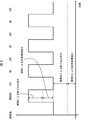
- (A) And (b) is a graph which shows an example of the change of the luminance value in the arbitrary pixel row which passes through a pupil area. It is a flowchart which shows an example of the process in the said authentication apparatus.
- FIG. 9 is a block diagram illustrating a configuration example of a main part of an authentication device according to a second embodiment.
- FIG. 11 is a graph illustrating an example of a temporal change in a luminance value of a pixel corresponding to a position where the second reflected light is reflected when illumination on and illumination off are continuously repeated temporally.
- FIG. 4 is a diagram illustrating an example of a relationship between a switching timing of lighting on and lighting off and a shutter opening / closing timing of an imaging unit. It is a flowchart which shows an example of the process in the said authentication apparatus.
- FIG. 13 is a block diagram illustrating a configuration example of a main part of an authentication device according to a third embodiment.
- (A) is a figure showing an example of an image acquired when an eyelid is open, and
- (b) is a figure showing an example of an image acquired when an eyelid is almost closed.
- FIG. 14 is a block diagram illustrating a configuration example of a main part of an authentication device according to a fourth embodiment.
- A is a figure which shows an example of the 1st image and 2nd image acquired when an imaging target is a living body's eyes
- (b) and (c) are cases where an imaging target is a printed matter.
- (d) is 1st image and 2nd image acquired when an imaging target is a printed matter with which the lens which imitated the cornea was mounted.
- It is a figure showing an example of two images.
- FIG. 1 is a block diagram illustrating a configuration example of a main part of an authentication device 1 according to the present embodiment.
- the authentication device 1 authenticates the subject H using the iris authentication technology.
- the subject H to be authenticated (collated) by the authentication device 1 is a living body including the eyeball HE.
- the subject H living body
- the authentication by the authentication device 1 is performed based on the result of the image analysis on at least one of the two eyes HE of the subject H (at least one of the left eye and the right eye).
- the authentication device 1 performs iris authentication using an image captured by the imaging unit 2 and including the iris region HIR (see FIG. 2) of the eyeball HE.
- the authentication device 1 includes an imaging unit 2 (imaging device), an illumination unit 3 (illumination device), a storage unit 4, a display unit 5, and a control unit 6.
- the authentication device 1 does not need to integrally include all of these members.
- the authentication device 1 only needs to have at least the function of the control unit 6. That is, at least one of the imaging unit 2, the illumination unit 3, the storage unit 4, and the display unit 5 may be realized as an external device of the authentication device 1.
- the imaging unit 2 functions as an image acquisition unit that acquires an image including the eyes of the subject H by imaging the subject H. Specifically, the imaging unit 2 acquires an image including the pupil region HPP and the iris region HIR of the eyeball HE of the subject H so that the control unit 6 performs iris authentication.
- the imaging unit 2 includes an imaging element such as a CCD (Charge Coupled Device) or a CMOS (Complementary Metal Oxide Semiconductor).
- the imaging unit 2 has wavelength sensitivity to light having a wavelength of 700 nm or more and 1000 nm or less. In this case, a luminance value (shading information) in the iris region HIR can be acquired with high accuracy.
- the wavelength is not limited to the above range unless this point is considered.
- the illumination unit 3 emits illumination light for irradiating the subject H. Specifically, the illumination unit 3 controls emission of illumination light emitted to the eyes of the subject H. More specifically, the illumination unit 3 emits illumination light to the eyes of the subject H at the timing when the imaging unit 2 captures an image. That is, the illumination unit 3 irradiates the eyeball HE with illumination light when imaging the eyeball HE.
- the authentication device 1 can also perform imaging in a dark place by using the illumination unit 3. Further, when an image is taken in an environment where the intensity of the ambient light is relatively high (for example, outdoors), the image can be acquired with the influence of the ambient light reduced.
- the illumination unit 3 emits illumination light corresponding to the wavelength sensitivity of the imaging unit 2, for example.
- the illumination section 3 emits illumination light having a wavelength of, for example, 700 nm or more and 1000 nm or less.
- the illuminating unit 3 provides the intensity of illumination light (the illumination at the eyes of the subject H) at the eyeball HE (the position of the subject H).
- the intensity of the illumination light may be adjusted so that the light intensity is 10 W / m 2 or more.
- the authentication device 1 can acquire a clear image to the extent that iris authentication can be performed accurately even outdoors.
- the upper limit of the intensity of the illumination light is determined in consideration of, for example, the power consumption of the illumination unit 3, the safety of the eyes of the subject H, and the ease of realization of the illumination unit 3.
- the authentication device 1 determines that the illumination unit 3 has entered a range of a predetermined distance from the eyes of the subject H (the illumination unit 3 has approached the eyes of the subject H).
- a proximity sensor (not shown) for detecting may be provided. When the proximity sensor detects that the illumination unit 3 has approached the eyes of the subject H, the illumination unit 3 stops emitting illumination light.
- the state in which the illumination light is emitted is also referred to as “illumination on”, and the state in which the illumination light is not emitted (including the stop of emission) is also referred to as “illumination off”.
- the storage unit 4 stores various programs executed by the control unit 6 and data used by the programs.
- the data includes a registered iris code to be collated with the acquired iris code.
- the display unit 5 displays an authentication result obtained by the control unit 6.
- the authentication device 1 may include a speaker that notifies the authentication result as sound data instead of or in addition to the display unit 5.
- the control unit 6 controls each unit of the authentication device 1 as a whole. Details of the control unit 6 will be described later.
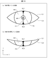
- FIG. 2A is a diagram illustrating an example of an image acquired by the imaging unit 2. As shown in FIG. 2A, an image of the first reflected light RL1 and the second reflected light RL2 is reflected in an image acquired by the imaging unit 2. Note that the images of the first reflected light RL1 and the second reflected light RL2 in the image are also simply referred to as the first reflected light RL1 and the second reflected light RL2.
- reflected light obtained as a result of reflecting the illumination light from the eyeball HE there are two types of reflected light obtained as a result of reflecting the illumination light from the eyeball HE, that is, a first reflected light RL1 and a second reflected light RL2.
- the first reflected light RL1 changes its reflection position depending on the angle at which the illumination light is incident on the eyeball HE, and is obtained by directly reflecting the illumination light on the corneal surface of the eyeball HE.
- the second reflected light RL2 is reflected immediately below the upper eyelid EL1 and immediately above the lower eyelid EL2, and the illumination light mainly reflected at the respective edges of the upper eyelid EL1 and the lower eyelid EL2 further reflects the corneal surface. It is obtained by reflection at.
- the second reflected light RL2 may include light obtained by further illuminating the illumination light reflected at the edge.
- the second reflected light RL2 includes at least light reflected on the edges of the upper eyelid EL1 and the lower eyelid EL2 and then reflected on the corneal surface near the boundary between the upper eyelid EL1 and the lower eyelid EL2.
- the corneal surface near the boundary with the upper eyelid EL1 means the corneal surface near the boundary between the upper eyelid EL1 and the eyeball HE when the eyeball HE is viewed from the front. The same applies to the corneal surface near the boundary with the lower eyelid EL2.
- the second reflected light RL2 is obtained by further reflecting the illumination light reflected at the edge on the corneal surface or the iris, because the structure of the edge of the eyelid is in front of the corneal surface near the boundary with the eyelid. This is caused by having a shape protruding from the surface.
- the edge of the upper eyelid EL1 has an eaves shape.
- the second reflected light RL2 includes the second reflected light RL21 reflected on the corneal surface near the boundary with the upper eyelid EL1, and the second reflected light RL22 reflected on the corneal surface near the boundary with the lower eyelid EL2.
- the second reflected light RL2 reflected on the boundary between the iris region HIR and the upper eyelid EL1 in the iris region HIR is the second reflected light RL21
- the second reflected light RL2 reflected on the boundary between the iris region HIR and the lower eyelid EL2 in the region HIR is the second reflected light RL22.
- the first reflection light RL1 is reflected inside the pupil region HPP by adjusting the positional relationship between the imaging unit 2 and the illumination unit 3. That is, the positional relationship between the imaging unit 2 and the illumination unit 3 is set such that the illumination light includes the first reflected light RL1 in the pupil region HPP.
- the first reflected light RL1 is not reflected in the iris region HIR. Therefore, the accuracy of iris authentication can be improved.
- the second reflected lights RL21 and RL22 are respectively provided at the boundary portions. Is reflected.
- the iris region HIR is on a substantially straight line that is a boundary portion between the iris region HIR and the upper eyelid EL1 and that passes through the pupil region HPP and is parallel to the eyelid opening / closing direction ( ⁇ Y-axis direction).
- the second reflected light RL21 is reflected.
- the second reflected light RL22 is reflected on the boundary between the iris region HIR and the lower eyelid EL2 in the iris region HIR and on the substantially straight line.
- the first reflected light RL1 and the second reflected light RL2 are reflected as reflected light images on the pupil region HPP and the iris region HIR in the image captured by the imaging unit 2. .
- the intensity of the illuminating light that can be realized from the viewpoint of the power consumption of the lighting unit and the size (module size) of the lighting unit that can be incorporated in the authentication device.
- the upper limit of the intensity of illumination light that can be realized has been raised.
- the intensity of illumination light increases, the influence of environmental light can be reduced in outdoor imaging. From this viewpoint, it is preferable to use an illumination unit having relatively high intensity of illumination light as the illumination unit 3.
- the intensity of the illumination light is relatively high, even if the positional relationship is adjusted so that the first reflected light RL1 is contained within the pupil region HPP, the size and the size cannot be ignored when performing iris authentication.
- the second reflected light RL2 having an intensity is reflected inside the iris region HIR.
- the authentication device 1 performs a process of removing the influence of the reflection of the second reflected light RL2, which occurs when the illumination unit 3 that can reduce the influence of environmental light is used. Therefore, the authentication device 1 includes the control unit 6 (particularly, the iris region acquisition unit 61).
- control unit 6 includes an iris area acquisition unit 61, an iris code acquisition unit 62, and an authentication unit 63.
- the iris region acquisition unit 61 acquires an authentication iris region CHIR in the image acquired by the imaging unit 2 excluding the image of the second reflected light RL2 reflected on the boundary portion of the iris region HIR.
- ((B) of FIG. 2 is a diagram for explaining an example of the processing of the iris area acquisition unit 61.
- the iris region acquiring unit 61 determines the width D1 of the second reflected light RL21 in the eyelid opening / closing direction and the second reflected light RL22. Of the eyelid in the opening and closing direction is calculated.
- the iris region acquisition unit 61 shifts the curve (boundary line BL1) along the upper eyelid EL1 and the edge of the eyeball HE toward the pupil region HPP ( ⁇ Y-axis direction) by the width D1.
- the iris region acquisition unit 61 shifts the curve (boundary line BL2) along the lower eyelid EL2 and the edge of the eyeball HE toward the pupil region HPP (+ Y axis direction) by the width D2.
- the iris region acquisition unit 61 specifies the regions included in the shifted boundary lines BL11 and BL12 in the iris region HIR as the authentication iris region CHIR (the hatched portion in FIG. 2B) used for iris authentication. I do. That is, the iris region acquisition unit 61 excludes the region outside the boundary line BL11 including the second reflected light RL21 and the region outside the boundary line BL12 including the second reflected light RL22 from the iris region HIR. , The authentication iris region CHIR is specified.
- the authentication iris area CHIR may be an area obtained by excluding the second reflected lights RL21 and RL22 from the iris area HIR. Therefore, the iris region acquisition unit 61 specifies, for example, the size and position of the second reflected lights RL21 and RL22, and specifies the region excluding only the second reflected lights RL21 and RL22 as the authentication iris region CHIR. It does not matter.
- the iris region acquisition unit 61 acquires the authentication iris region CHIR by excluding all of the second reflected lights RL21 and RL22 from the iris region HIR, but is not limited thereto.
- the iris region acquisition unit 61 may acquire the authentication iris region CHIR excluding only one of the second reflected lights RL21 and RL22. In this case, the width of the eyelid in the opening and closing direction may be calculated only for the excluded second reflected light RL2.
- the iris region acquisition unit 61 may acquire the authentication iris region CHIR excluding a part of the second reflected light RL21 and / or a part of the second reflected light RL22.
- the iris region acquisition unit 61 may acquire the authentication iris region CHIR in the image acquired by the imaging unit 2 excluding at least a part of the second reflected light RL2 from the iris region HIR. Even when a part of the second reflected light RL2 is excluded, the accuracy of the iris authentication can be improved as compared with the case where the iris authentication is performed without excluding the second reflected light RL2 at all. However, when all of the second reflected light RL2 is excluded, the accuracy of iris authentication can be further improved.
- the detection of the width D1 and the width D2 and the detection of the boundary lines BL1 and BL2 based on the image acquired by the imaging unit 2 may use a known image processing technique. Further, the detection of the size and the position of the pupil region HPP and the detection of the size and the position of the second reflected light RL2 based on the image acquired by the imaging unit 2 may use a known image processing technique. . The same applies to other image processing by the control unit 6.
- the iris code acquisition unit 62 acquires (creates) an iris code used for performing iris authentication based on the authentication iris region CHIR acquired by the iris region acquisition unit 61.
- the iris code obtaining unit 62 obtains an iris code for performing iris authentication using the image of the authentication iris region CHIR.
- a known method may be used for creating an iris code by the iris code acquisition unit 62.
- the authentication unit 63 performs iris authentication using the authentication iris region CHIR. Specifically, the authentication unit 63 collates the iris code created based on the authentication iris region CHIR (the iris code acquired by the iris code acquisition unit 62) with the registered iris code registered in advance in the storage unit 4. Then, the iris of the subject H is authenticated.
- a known method may be used for the authentication determination by the authentication unit 63. For example, the authentication unit 63 may calculate a Hamming distance HD between the registered iris code and the iris code, and may perform the collation based on the Hamming distance HD.
- the authentication unit 63 determines that the degree of coincidence between the registered iris code and the iris code is within a predetermined range when the hamming distance HD is equal to or less than a predetermined hamming distance threshold HDth. In this case, the authentication unit 63 determines that the iris authentication for the subject H has been successful. On the other hand, when the matching degree is out of the predetermined range (when the hamming distance HD is larger than the hamming distance threshold HDth), the authentication unit 63 determines that the iris authentication has failed.
- the iris region acquisition unit 61 may specify the position and the size of the second reflected light RL2 based on the respective luminance values of a plurality of pixels constituting the iris region HIR included in the image. In other words, the iris region acquisition unit 61 may specify the region of the image of the second reflected light RL2 based on the brightness of each of the pixels included in the iris region HIR in the image. In this case, the area (size) of the image of the second reflected light RL2 can be easily specified. Specifically, the iris area acquisition unit 61 specifies, for example, the widths D1 and D2 by specifying the position and the size of the second reflected light RL2 based on the luminance value.
- the iris area acquisition unit 61 configures the pixels having a luminance value equal to or more than a predetermined value (eg, “TH1” shown in FIG. 4A) among the plurality of pixels as the second reflected light RL2. It is determined that the pixel to be used.
- the iris area acquisition unit 61 extracts, for example, the luminance values of a plurality of pixel columns (see FIG. 3) formed in the eyelid opening / closing direction from the image, and for each of the pixel columns, a pixel having a luminance value equal to or more than a predetermined value May be specified.
- the iris region acquisition unit 61 determines a set of pixels in the iris region HIR among the pixels having the luminance value determined to be equal to or greater than the predetermined value, in the region of the image of the second reflected light RL2 (specifically, the size thereof). And position).
- the iris area acquisition unit 61 can also specify the position and size of the first reflected light RL1.
- the iris region acquisition unit 61 determines the position and the size of the first reflected light RL1 based on the luminance values of a plurality of pixels constituting the pupil region HPP included in the image. To identify.
- the iris region acquisition unit 61 may specify the region of the image of the first reflected light RL1 based on the luminance of each of the plurality of pixels included in the pupil region HPP in the image.
- the iris region acquiring unit 61 for example, among the pixels having the luminance value determined to be equal to or larger than the predetermined value, sets a set of pixels included in the pupil region HPP to an image region of the first reflected light RL1 (specifically, Is specified as its size and position).
- the predetermined value for specifying the first reflected light RL1 and the predetermined value for specifying the second reflected light RL2 need not be the same value, and may be different from each other.
- the predetermined value may be set to a size that can specify each of the first reflected light RL1 and the second reflected light RL2 by an experiment or the like.
- the iris region acquisition unit 61 can specify the width D1 or D2 from the captured image without using the boundary lines BL1 and BL2 that can be acquired by a known technique.
- the iris region acquisition unit 61 calculates, for example, a distance between pixels at the farthest position in the eyelid opening / closing direction as the width D1 or D2 among a plurality of pixels specified as the second reflected light RL2.
- the iris area acquisition unit 61 specifies a pixel closest to the pupil area HPP in the + Y-axis direction as a lower end of the second reflected light RL21 among the pixels having a luminance value equal to or greater than the predetermined value.
- the iris region acquiring unit 61 specifies a pixel farthest from the pupil region HPP in the + Y-axis direction (a pixel closest to the upper eyelid EL1) in a pixel row including the pixel as the upper end of the second reflected light RL21. Then, the iris area acquisition unit 61 calculates the distance between the upper end and the lower end as the width D1.
- the iris region acquiring unit 61 specifies, as a top end of the second reflected light RL22, a pixel closest to the pupil region HPP in the ⁇ Y-axis direction among pixels having a luminance value equal to or greater than the predetermined value.
- the iris area acquisition unit 61 specifies, as a lower end of the second reflected light RL22, a pixel farthest from the pupil area HPP in the pixel row including the pixel (a pixel closest to the lower eyelid EL2) in the -Y-axis direction. Then, the iris region acquisition unit 61 calculates the distance between the upper end and the lower end as the width D2.
- the iris area acquisition unit 61 can also specify the width D1 or D2 from the captured image using the boundary lines BL1 and BL2 acquired by a known technique, for example.
- the iris area acquisition unit 61 sets, as a lower end of the second reflected light RL21, a pixel farthest from the upper eyelid EL1 side boundary line BL1 acquired by a known technique among pixels having a luminance value equal to or greater than the predetermined value. Identify. Then, the iris area acquisition unit 61 calculates the distance between the lower end and the boundary line BL1 as the width D1.
- the iris area acquisition unit 61 determines, from among the pixels having the luminance value equal to or greater than the predetermined value, the pixel farthest from the lower eyelid EL2 side boundary line BL2 acquired by a known technique, the upper end of the second reflected light RL22. To be specified. Then, the iris area acquisition unit 61 calculates the distance between the upper end and the boundary line BL2 as the width D2.
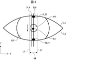
- FIG. 3 is a diagram for explaining an example of a process for specifying the size of the second reflected light RL2.
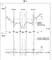
- FIGS. 4A and 4B are graphs (characteristics of luminance values) showing an example of a change in luminance value in an arbitrary pixel row passing through the pupil region HPP.
- FIGS. 4A and 4B the vertical axis represents the luminance value
- the horizontal axis represents the pixel position.
- the direction in which the horizontal axis extends corresponds to the direction of the arrow shown in FIG. That is, 0 on the horizontal axis indicates the uppermost pixel in the image shown in FIG. 3, and as the value on the horizontal axis increases, the image shown in FIG. The position of the pixel changes.
- FIGS. 4A and 4B show the results when the illumination unit 3 having two light sources is used. For this reason, in FIGS. 4A and 4B, there are two positions where the luminance value sharply increases at the positions of the pixels corresponding to the pupil region HPP. It should be noted that both of the second reflected lights RL21 and RL22 are generated even if the illumination unit 3 has one light source.
- FIG. 3 shows the pixel columns PLA and PLB as an example of the pixel column formed in the opening and closing direction of the eyelids.
- the pixel row PLA is a pixel row that passes through the pupil region HPP and the iris region HIR and does not pass through the first reflected light RL1, the second reflected light RL21, and the RL22.
- the pixel row PLB is a pixel row that passes through the pupil region HPP and the iris region HIR, and passes through the first reflected light RL1, the second reflected light RL21, and the RL22.
- the luminance value of the pixel column PLA increases as the value of the horizontal axis increases (in the image of FIG. 3, the pixel position is changed to the eyelid (skin) region and the iris region HIR in the arrow direction). (As it changes), and the luminance value becomes minimum near the approximate center of the pupil region HPP.
- the position of the pixel changes to the iris region HIR and the eyelid region. Therefore, as the value on the horizontal axis increases from approximately near the center of pupil region HPP, the luminance value of pixel column PLA increases.
- a predetermined value TH1 (a threshold value of an appropriate luminance value for determining the first reflected light RL1 and the second reflected light RL2) is set, as shown in FIG. 4A, the iris region HIR and the pupil region HPP There is no pixel having a luminance value equal to or more than the predetermined value TH1. Therefore, by setting the predetermined value TH1, the iris region acquiring unit 61 can specify that the pixels forming the first reflected light RL1 and the second reflected light RL2 do not exist in the pixel row PLA.
- the pixel row PLB there are pixels whose luminance values sharply increase at the positions of the pixels corresponding to the iris region HIR and the positions of the pixels corresponding to the pupil region HPP.
- the luminance value increases at that position.
- the predetermined value TH1 is set, as shown in FIG. 4A, there are pixels having a luminance value equal to or higher than the predetermined value TH1 in the pupil region HPP and the iris region HIR.
- the iris region obtaining unit 61 can specify that the pixels forming the first reflected light RL1 and the second reflected light RL2 exist in the pixel row PLB.
- the iris region acquisition unit 61 can specify the positions of the pixels forming the first reflected light RL1 and the second reflected light RL2.
- the iris area acquisition unit 61 can easily specify the first reflected light RL1 and the second reflected light RL2 in the image by determining whether the luminance value of each pixel is equal to or more than the predetermined value TH1.
- the region where the iris region acquiring unit 61 acquires the luminance value and determines whether the pixels included in the image are the pixels constituting the second reflected light RL2 are the boundary lines BL1 and BL2 in the image. And a region surrounded by two straight lines L1 and L2 defining the maximum width of the pupil region HPP in a direction perpendicular to the opening and closing direction of the eyelids.
- the region where the iris region acquiring unit 61 acquires the luminance value and determines whether the pixels included in the image are the pixels constituting the first reflected light RL1 or not. It is.
- the iris area acquisition unit 61 acquires the luminance value of the pixel in the above-described area in the image, and determines whether the pixel is a pixel forming the image of the first reflected light RL1 or the second reflected light RL2. It may be determined whether or not. In this case, the range for performing the above determination is limited. Therefore, the process of specifying the first reflected light RL1 and the second reflected light RL2 in the image can be performed more easily.
- the direction perpendicular to the opening and closing direction of the eyelids indicates the X-axis direction.
- the maximum width is, for example, the pupil diameter DM.
- the iris area acquisition unit 61 may specify the first reflected light RL1 and the second reflected light RL2 as follows.
- the iris area acquisition unit 61 determines, for each of a plurality of pixel rows formed along the direction (X-axis direction) perpendicular to the eyelid opening and closing direction in the area sandwiched between the two straight lines L1 and L2, The average value of the luminance values of the pixels constituting the row is calculated.
- An example of a graph showing the average value of the luminance values of each pixel row is shown as “average value of pixel columns” in FIG.
- the iris region acquisition unit 61 calculates a luminance value of an arbitrary pixel forming an arbitrary pixel column formed along the opening / closing direction and a luminance value corresponding to a pixel row including the arbitrary pixel. The difference value from the average value is calculated. When the difference value is equal to or greater than the predetermined value TH2 (see FIG. 4B), the iris region acquiring unit 61 determines, for any pixel included in the iris region HIR, a pixel constituting the second reflected light RL2. Is determined. On the other hand, the iris region acquisition unit 61 determines that any pixel included in the pupil region HPP is a pixel constituting the first reflected light RL1.
- FIG. 4B shows a graph of the above difference value when an arbitrary pixel column is a pixel column PLA and a pixel column PLB and the position of the pixel is changed in the direction of the arrow in FIG.
- a predetermined value TH2 for determining whether or not the pixel constitutes the first reflected light RL1 and the second reflected light RL2 (an appropriate luminance value for determining the first reflected light RL1 and the second reflected light RL2) Is set, there is no pixel having the predetermined value TH2 or more.
- the iris region acquisition unit 61 can specify that the pixels forming the first reflected light RL1 and the second reflected light RL2 exist in the pixel row PLB.
- the iris region acquisition unit 61 can specify the positions of the pixels forming the first reflected light RL1 and the second reflected light RL2.
- the predetermined values TH1 and TH2 need not be a common threshold for specifying the first reflected light RL1 and the second reflected light RL2.
- predetermined values for specifying the first reflected light RL1 and the second reflected light RL2 may be respectively set.
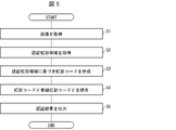
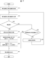
- FIG. 5 is a flowchart illustrating an example of a process in the authentication device 1.
- the imaging unit 2 acquires an image including the iris region HIR of the eyeball HE of the subject H (S1; image acquisition step).
- the illumination unit 3 emits illumination light to the eyes of the subject H at a timing when the imaging unit 2 captures an image.
- the first reflected light RL1 is reflected in the pupil region HPP
- the second reflected light RL2 is reflected in the iris region HIR.
- the imaging unit 2 outputs the obtained image to the iris area obtaining unit 61.
- the iris region acquiring unit 61 analyzes the received image to acquire an authentication iris region CHIR excluding at least a part of the image of the second reflected light RL2 (S2: iris region acquiring step).
- the iris region acquiring unit 61 outputs the acquired information on the authenticated iris region CHIR (eg, shading information of each pixel constituting the authentic iris region CHIR) to the iris code acquiring unit 62.
- the iris code acquisition unit 62 creates an iris code based on the acquired information (S3; iris code acquisition step).
- the iris code acquisition unit 62 outputs the created iris code to the authentication unit 63.
- the authentication unit 63 reads the registered iris code registered in the storage unit 4 and performs iris authentication on the subject H by comparing the received iris code with the registered iris code (S4; authentication step). That is, the authentication unit 63 performs iris authentication using the authentication iris region CHIR.
- the authentication unit 63 outputs the result of the iris authentication via the display unit 5 (S5; output step).
- a case where one image (still image) is captured and iris authentication is performed on the image is illustrated.
- a moving image may be captured, and iris authentication (moving image authentication) may be performed on a frame constituting the moving image.
- a plurality of images may be acquired in a short time by capturing a moving image. Therefore, the iris authentication is performed in order from the captured image while continuing the image acquisition step (imaging step). May be advanced at the same timing as the image acquisition step. In this case, when the iris authentication succeeds, the image acquisition (moving image capturing) may be stopped, and the authentication unit 63 may output the authentication result.
- an authentication result indicating that the iris authentication has failed is output to the authentication unit 63. You may let me.
- Example> The result of performing iris authentication based on the authentication iris region CHIR acquired by the authentication device 1 of the present embodiment is compared with the result of performing iris authentication based on the iris region HIR acquired by the authentication device of the comparative example.
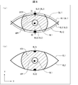
- FIG. 6A is a diagram illustrating an example of the authentication iris region CHIR acquired by the authentication device 1
- FIG. 6B is a diagram illustrating an example of the iris region HIR acquired by the authentication device of the comparative example. It is.
- the positional relationship between the imaging unit and the illumination unit is determined by the first reflected light RL1 as described above. Is set to be reflected in the pupil region HPP. That is, in both the image acquired by the authentication device 1 and the image acquired by the authentication device of the comparative example, the first reflected light RL1 is reflected in the pupil region HPP, but is reflected in the iris region HIR. Not in. On the other hand, the second reflected lights RL21 and RL22 are reflected on the above-described boundary portion of the iris region HIR.
- the authentication device 1 causes the iris region acquisition unit 61 to acquire the authentication iris region CHIR shown as a hatched portion in FIG. 6A from the image captured by the imaging unit 2. That is, the authentication iris area CHIR acquired by the iris area acquisition unit 61 does not include the second reflected lights RL21 and RL22.
- the authentication device of the comparative example includes an iris region acquisition unit, an iris code acquisition unit, and an authentication unit, like the authentication device 1.
- the iris region acquisition unit of the comparative example acquires the iris region HIR shown as a hatched portion in FIG. 6B from the image captured by the imaging unit. That is, the second reflected lights RL21 and RL22 are included in the iris region HIR acquired by the iris region acquisition unit of the comparative example.
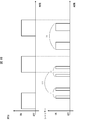
- FIG. 7 shows a cumulative probability plot of the hamming distance HD obtained by the authentication device 1 performing iris authentication (verification) based on the authentication iris region CHIR, and an iris authentication (verification) based on the iris region HIR performed by the authentication device of the comparative example. And a cumulative probability plot of the hamming distance HD obtained by performing the above. 7, the vertical axis indicates the cumulative probability distribution of the Hamming distance HD, and the horizontal axis indicates the Hamming distance HD.
- each part of the authentication device 1 is denoted by a reference numeral
- each part of the authentication device of the comparative example is not denoted by a reference numeral.
- the imaging unit 2 and the imaging unit have wavelength sensitivity to light having a wavelength of 800 nm or more and 850 nm or less.
- the linear distance between the eyes of the subject H and the authentication device 1 and the linear distance between the eyes of the subject H and the authentication device of the comparative example are both 30 cm.
- the intensity of illumination light at the eyes of the subject H is 15 W / m 2 .
- the iris region obtaining unit 61 obtains the authentication iris region CHIR from the image captured under the above conditions (see FIG. 6A).
- the iris code acquisition unit 62 has created an iris code based on the authenticated iris region CHIR.
- the authentication unit 63 calculates the hamming distance HD between the created iris code and the registered iris code of the subject H registered in advance.
- the iris region acquisition unit acquired the iris region HIR from the image captured under the above conditions (see FIG. 6B).
- the iris code acquisition unit created an iris code from the iris region HIR.
- the authentication unit calculated a hamming distance HD between the created iris code and the registered iris code (same as the registered iris code used in the authentication device 1).
- 60 registered iris codes to be compared with the iris code are prepared in advance.
- the authentication device 1 and the authentication device of the comparative example respectively obtained six iris codes as iris codes to be compared with the registered iris codes.
- the authentication device 1 and the authentication device of the comparative example each calculate the hamming distance HD of each of the 60 registered iris codes for one of the six iris codes.
- the authentication device 1 and the authentication device of the comparative example each similarly calculate the hamming distance HD for the remaining five devices. That is, the authentication device 1 and the authentication device of the comparative example each calculated 360 hamming distance HD as the calculation result of the hamming distance HD.
- FIG. 7 The results of FIG. 7 are plotted while accumulating the Hamming distance HD calculated by each of the authentication device 1 and the authentication device of the comparative example.
- “Embodiment 1" in the figure shows a plotting result of the hamming distance HD calculated by the authentication device 1
- “Comparative Example” in the diagram shows a plotting result of the hamming distance HD calculated by the authentication device of the comparative example. .
- the iris code and the registered iris code are composed of a plurality of parts (for example, 8 ⁇ 128 parts), and in each part, any one of information 0 and 1 is stored based on the density information of the iris area HIR. It has been created by.
- the authentication unit 63 and the authentication unit compare the corresponding parts of the iris code and the registered iris code to determine whether the stored information matches. This determination is made for all parts, and the ratio of the number of parts whose information does not match the total number of parts is calculated as the hamming distance HD.
- the Hamming distance HD 0 is an ideal value where the iris code and the registered iris code completely match. Also, between the iris code acquired from the person and the iris code acquired from another person, the information of 0 and 1 is about 50% identical. Therefore, in this case, the hamming distance HD is about 0.5. In other words, it can be said that the smaller the value of the hamming distance HD, the higher the authentication accuracy.
- the hamming distance HD calculated by the authentication device 1 is smaller than the hamming distance HD calculated by the authentication device of the comparative example.
- the value of the hamming distance HD having the cumulative existence probability of 50% is 0.294 in the authentication device of the comparative example, and is 0.255 in the authentication device 1. Therefore, it can be seen that the iris authentication by the authentication device 1 has higher authentication accuracy than the comparative example.
- the authentication device of the comparative example has an authentication ratio of 20%, whereas the authentication device 1 has an authentication ratio of 90% or more. It turns out that it has an authentication rate.
- the authentication device 1 detects the second reflected light RL2.
- the iris authentication is performed based on the authentication iris region CHIR excluding at least a part of the image. Thereby, the authentication device 1 can perform the iris authentication in a state where the influence of the reflection of the illumination light on the iris region HIR is reduced. Therefore, the accuracy of iris authentication can be improved.
- the authentication device 1 When acquiring the authentication iris region CHIR excluding all of the second reflected light RL2, the authentication device 1 acquires an iris authentication iris region in which the first reflected light RL1 and the second reflected light RL2 are not reflected. it can. Therefore, the authentication device 1 can further improve the accuracy of iris authentication.
- FIG. 8 is a block diagram illustrating a configuration example of a main part of the authentication device 1A of the present embodiment. As shown in FIG. 8, the authentication device 1A is different from the authentication device 1 in that the authentication device 1A includes a control unit 6A having an image generation unit 64.
- the image generation unit 64 generates an ambient light-removed image by removing at least a part of the reflection of the ambient light from the image acquired by the imaging unit 2.
- the iris region obtaining unit 61 obtains an authentication iris region CHIR in the environment light removed image excluding at least a part of the image of the second reflected light RL2.
- the image generation unit 64 may calculate, based on the luminance value of the first image obtained when the eyeball HE is irradiated with the illumination light, a second image obtained when the eyeball HE is not irradiated with the illumination light. A difference image from which the luminance value has been subtracted is generated as an ambient light removed image. In this case, the image generation unit 64 can generate the ambient light removed image by a simple method.
- the lighting unit 3 switches lighting on and off continuously in time.
- the image capturing unit 2 captures an image of the eyeball HE in accordance with the switching timing of the illumination ON and the illumination OFF.
- the image generating unit 64 calculates the respective luminance values of the plurality of pixels constituting the first image acquired when the illumination is turned on, and the respective luminance values of the plurality of pixels constituting the second image acquired when the illumination is turned off. get.
- the image generator 64 subtracts the luminance value of the second image from the luminance value of the first image for each corresponding pixel in the first image and the second image.
- the image generation unit 64 acquires an image having a luminance value as a result of subtraction for each pixel as a difference image.
- FIG. 9 is a graph showing an example of a temporal change of the luminance value of the pixel corresponding to the position where the second reflected light RL2 is reflected when the lighting-on and the lighting-off are repeated continuously in time. Note that FIG. 9 illustrates a case where the time during which the light is on and the time during which the light is off are substantially the same, but these times need not be substantially the same.
- the luminance value of the pixel is composed of the following four components.
- -Reflection component due to lighting The illumination light is mainly obtained by specular reflection on the corneal surface.
- -An iris information component due to lighting It is obtained by diffusely reflecting illumination light at the iris.
- -Reflected components due to ambient light It is mainly obtained by specular reflection of environmental light on the corneal surface.
- Environmental light is obtained by diffuse reflection of the iris.
- the luminance value of the pixel is composed of two components, a reflection component due to ambient light and an iris information component due to ambient light. Therefore, by calculating the difference between the luminance values of the first image and the second image as described above, it is possible to obtain an ambient light-removed image from which the glare component due to ambient light and the iris information component due to ambient light have been removed. Note that the second reflected light RL2 having a reflection component due to illumination is excluded by the iris region acquisition unit 61.
- the iris information component due to the ambient light may be removed.
- the intensity of the ambient light changes depending on the situation at the time of iris authentication (whether an image is acquired outdoors or indoors, etc.). Further, the intensity of the ambient light also changes at the position of the iris region HIR in the acquired image (that is, the position of the pixel constituting the iris region HIR).
- the intensity of the illumination light is controlled to a predetermined intensity. Therefore, accurate iris authentication is performed by removing the iris information component due to environmental light whose intensity changes due to the situation and using an image that leaves only the iris information component due to the illumination light whose intensity does not easily change due to the situation. Can be.
- FIG. 10 is a diagram illustrating an example of the relationship between the timing of switching the illumination on and the illumination off and the timing of opening and closing the shutter of the imaging unit 2.
- the imaging unit 2 acquires the first image when the illumination is on, and acquires the second image after the illumination is off.
- the second image is acquired when the illumination is turned off before the illumination is turned on, and the first image is acquired after the illumination is turned on.
- the image generation unit 64 when the image generation unit 64 acquires the first image and the second image while switching the illumination on and the illumination off a plurality of times, the first image acquired when the illumination is on and the next illumination off A difference image is generated based on the second image acquired at that time (see (i) of FIG. 10).
- the image generation unit 64 may generate a difference image based on the second image acquired when the illumination is turned off and the first image acquired when the next illumination is turned on ((ii) in FIG. 10). reference). That is, the image generation unit 64 generates a difference image based on the first image and the second image acquired continuously. In this case, the change of the ambient light between the lighting ON and the lighting OFF can be reduced. Further, it is possible to prevent the displacement of the corresponding pixel due to the influence of body movement. Therefore, the image generation unit 64 can generate a difference image having a luminance value that hardly includes components due to environmental light.
- the image generating unit 64 may generate a plurality of difference images based on a set of the plurality of first images and the second images, and use an image obtained by integrating luminance values of these difference images as an ambient light removed image.
- the image generation unit 64 generates an image obtained by integrating the luminance values of the difference image generated in (i) and the difference image acquired in (ii). I do.
- the image generation unit 64 generates an image in which the luminance value of this image and the luminance value of the difference image generated based on the first image and the second image acquired at the next timing of (ii) are integrated. .
- An image generated as a result of repeating this integration is defined as an ambient light removed image.
- the shutter open / close time can be set arbitrarily. If this condition is satisfied, the shutter opening time shown in (i) and (ii) may be set, or the shutter opening time shown in (iv) may be set.
- the image generation unit 64 generates the difference image based on the first image and the second image acquired continuously. You don't have to. Further, the switching of the illumination on and the illumination off may be performed once (the set of the first image and the second image to be acquired is one set). Further, as a technique for generating the difference image as the ambient light-removed image, various known techniques can be adopted (for example, a technique disclosed in Patent Document 1 or 2).
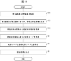
- FIG. 11 is a flowchart illustrating an example of processing in the authentication device 1A.
- the imaging unit 2 acquires a first image when the illumination is on and acquires a second image when the illumination is off as an image including the iris region HIR (S11; image acquisition step).
- the imaging unit 2 outputs the obtained image to the image generation unit 64.
- the image generation unit 64 generates an ambient light removal image based on the received first image and second image (S12; image generation step). For example, the image generation unit 64 generates a difference image obtained by subtracting the luminance value of the second image from the luminance value of the first image as an ambient light removed image. The image generation unit 64 outputs the generated environment light removed image to the iris region acquisition unit 61.
- the iris region acquiring unit 61 acquires the authentication iris region CHIR excluding at least a part of the image of the second reflected light RL2 by analyzing the received environment light removed image (S13; iris region acquiring step). Thereafter, the processing of S3 to S5 described in the first embodiment is performed.
- the accuracy of the iris authentication is reduced because the iris information includes the ambient light reflected on the corneal surface. That is, when the environment light is reflected in the iris area, the accuracy of the iris authentication is reduced similarly to the reflection of the illumination light.
- the authentication device 1A acquires the authentication iris region CHIR from the ambient light removed image from which at least a part of the reflection of the ambient light has been removed, thereby performing the iris authentication in a state where the influence of the reflection of the ambient light is reduced. it can. Therefore, the accuracy of iris authentication can be improved. In addition, when the authentication device 1A generates an environment light-removed image from which all of the reflection of the environment light has been removed, the accuracy of the iris authentication can be further improved.
- FIG. 12 is a block diagram illustrating a configuration example of a main part of the authentication device 1B of the present embodiment. As shown in FIG. 12, the authentication device 1B is different from the authentication device 1 in that the authentication device 1B includes a control unit 6B having an image determination unit 65.
- the image determination unit 65 determines whether the image is appropriate as an image for performing iris authentication, based on the size of the iris region HIR included in the image captured by the imaging unit 2. Even if an image is acquired, if the image hardly includes the iris region HIR, the result of the iris authentication is “failure (NG)”. In other words, when the eyelid opening (opening degree) is relatively low, it can be said that the image is not suitable as an image for performing iris authentication. Therefore, in order to obtain an image that is appropriate as an image for performing iris authentication, the image determining unit 65 determines whether or not the image is appropriate.
- FIG. 13A is a diagram illustrating an example of an image acquired when the eyelid is open
- FIG. 13B is a diagram when the eyelid is almost closed (not completely closed).
- FIG. 5 is a diagram showing an example of an image acquired in FIG. If the eyelids are slightly open (ie, unless the eyelids are completely closed), the cornea is exposed. For this reason, if the eyelid is not completely closed, as shown in FIGS. 13A and 13B, the eyelid is located in the vertical direction ( ⁇ Y-axis direction) when viewed from the pupil region HPP and the upper eyelid The second reflected lights RL21 and RL22 are reflected immediately below EL1 and directly above the lower eyelid EL2, respectively.
- the distance between the image of the second reflected light RL21 near the upper eyelid EL1 and the image of the second reflected light RL22 near the lower eyelid EL2 included in the image it is possible to use the distance between the image of the second reflected light RL21 near the upper eyelid EL1 and the image of the second reflected light RL22 near the lower eyelid EL2 included in the image. it can.
- the image determination unit 65 determines whether the image is appropriate as an image for performing iris authentication by determining whether the distance is equal to or greater than a predetermined distance (reference opening). Specifically, if the distance is equal to or longer than a predetermined distance, the image is determined to be appropriate as an image for performing iris authentication, and if shorter than the predetermined distance, it is determined to be inappropriate as the image.
- a predetermined distance may be set, for example, by an experiment or the like to a distance at which iris authentication can be performed.
- the image determination unit 65 determines that the calculated distance D11 is equal to or longer than a predetermined distance.
- the image determination unit 65 determines that the calculated distance D12 is less than the predetermined distance.
- the image determination unit 65 can perform iris authentication using the acquired image, and thus causes the iris region acquisition unit 61 to acquire the authentication iris region CHIR in the image.
- the result is “failure (NG)” even if the iris authentication is performed using the acquired image.
- the acquisition is urged to the subject H.
- the image determination unit 65 causes the display unit 5 to perform a display requesting reacquisition of an image.
- the subject H operates the imaging unit 2 based on this display to cause the imaging unit 2 to reacquire an image including the iris region HIR.
- the authentication time can be reduced as compared with a case where an iris code is created using an inappropriate image as an image to be subjected to iris authentication, the iris authentication is performed using the iris code, and the image is reacquired.
- the image determination unit 65 cannot specify the reflection of the second reflected lights RL21 and RL22 in the image. Therefore, when the reflection of the second reflected lights RL21 and RL22 cannot be specified in the image, the image determination unit 65 estimates that the image is obtained with the eyes closed, and the image is subjected to iris authentication. It is determined that the image to be performed is inappropriate.
- the calculation of the distance may be performed together with the calculation of the magnitudes of the second reflected lights RL21 and RL22 by the iris area acquisition unit 61.
- the iris area acquisition unit 61 may have the function of the image determination unit 65.
- the predetermined distance may be defined by an index whose distance does not change depending on the imaging environment. That is, the predetermined distance may be set in association with the size of the index. Examples of the index include the distance between the outer corner of the eye and the inner corner of the eye, or the diameter of the iris region HIR (iris diameter). Since the diameter of the pupil region HPP (pupil diameter DM) changes depending on the illuminance of visible light included in the ambient light, it is not suitable for the above index.
- FIG. 14 is a flowchart illustrating an example of processing in the authentication device 1B.
- the imaging unit 2 acquires an image including the iris region HIR (S1; image acquisition step).
- the imaging unit 2 outputs the obtained image to the image determination unit 65.
- the image determining unit 65 calculates the distance between the second reflected lights RL21 and RL22 by specifying the positions of the second reflected lights RL21 and RL22 reflected in the received image (S21; distance calculating step). The image determining unit 65 determines whether the calculated distance is equal to or longer than a predetermined distance (S22; distance determining step).
- the image determination unit 65 determines that the obtained image is appropriate as an image for performing iris authentication. In this case, the image determination unit 65 instructs the iris region acquisition unit 61 to acquire the authentication iris region CHIR. Thus, the processing of S2 to S5 described in the first embodiment is performed.
- the image determination unit 65 determines that the obtained image is inappropriate as an image for performing iris authentication. In this case, the image determination unit 65 determines whether or not the number of times of obtaining the image is equal to or more than the predetermined number (S23; number determination step).
- the image determination unit 65 displays via the display unit 5 a message prompting reacquisition of an image.
- the imaging unit 2 receives the operation of the subject H and reacquires an image including the iris region HIR (S24; image reacquisition step). Thereafter, the process proceeds to S21.
- the image determination unit 65 notifies the authentication unit 63 of that. Upon receiving this notification in S5, the authentication unit 63 determines that iris authentication cannot be performed (iris authentication has failed), and outputs the determination result via the display unit 5.
- the authentication device 1B can accurately determine whether or not the acquired image is an image for performing iris authentication by a simple method. Therefore, the authentication device 1B can prevent performing iris authentication using an image in which the eyelids are not sufficiently opened. Further, it is possible to prevent an iris code created using the image from being registered as a registered iris code. The authentication device 1B does not perform authentication using an inappropriate image as an image for performing iris authentication. Therefore, the time required for iris authentication can be reduced.
- the opening degree of the eyelid can be calculated by detecting the boundary lines BL1 and BL2 using a known technique.
- detection of the boundary lines BL1 and BL2 may be unstable due to the influence of the eyelashes.
- the boundaries BL1 and BL2 tend to be erroneously detected as being outside the boundaries of the actual eyelids.
- the eyelid opening degree is set to an opening degree suitable for performing iris authentication even though the eyelids are actually closing. It is erroneously determined that there is.
- the authentication device 1B uses the distance between the second reflected lights RL21 and RL22 to determine whether or not the opening of the eyelid is an opening suitable for performing iris authentication. Therefore, the determination can be accurately performed without being affected by the eyelashes. That is, the authentication device 1B can accurately determine whether or not the image is for performing iris authentication. Further, the authentication device 1B does not perform iris authentication using an image affected by eyelashes. That is, since unnecessary iris authentication is not performed, the time required for iris authentication can be reduced.
- FIG. 15 is a block diagram illustrating a configuration example of a main part of the authentication device 1C of the present embodiment. As shown in FIG. 15, the authentication device 1C differs from the authentication device 1 in that the authentication device 1C includes a control unit 6C having a forgery determination unit 66.
- the forgery determination unit 66 determines whether or not the imaging target is a forgery for the purpose of preventing impersonation using a printed matter such as a photograph of an eyeball to impersonate another person and bypass the iris authentication. Specifically, the forgery determination unit 66 determines whether the imaging target is a forgery by comparing the first image obtained when the illumination is on and the second image obtained when the illumination is off. I do.
- the forgery determination unit 66 determines that the second image does not include the first reflected light RL1 even though the first image includes the first reflected light RL1, the forgery determination unit 66 determines that the imaging target is not included. You may decide that it is not a fake. This determination method is referred to as a determination method MA.
- the forgery determination unit 66 determines that the first image includes the first reflected light RL1 and the second reflected light RL2, although the first image includes the first reflected light RL1 and the second reflected light RL2. If it is determined that the object has not been copied, it may be determined that the imaging target is not a forgery.
- This determination method is referred to as a determination method MB. In the case of the determination method MB, the accuracy of the forgery determination can be improved.
- the forgery determination unit 66 generates, for example, a difference image between the first image and the second image, so that the first reflected light RL1 and / or the second reflected light RL2 are included in each of the first image and the second image. It is determined whether or not it is included.
- the difference image is generated, the influence of the ambient light can be eliminated as described in the second embodiment, so that erroneous determination of iris authentication due to the reflection of the ambient light can be avoided.
- the method described in the first embodiment can be used as a method for specifying the first reflected light RL1 and / or the second reflected light RL2 in the image.
- the forgery determination unit 66 determines that the imaging target is not a forgery, the forgery determination unit 66 causes the iris region acquisition unit 61 to acquire the authentication iris region CHIR in the acquired image. On the other hand, when determining that the imaging target is a counterfeit, the forgery determination unit 66 may prompt the subject H to reacquire the image via the display unit 5. When the imaging target is a forgery, the authentication unit 63 may output via the display unit 5 that the iris authentication has failed without prompting the user to reacquire the image.
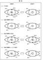
- FIG. 16 is a diagram illustrating an example of a first image and a second image acquired when an imaging target is an eye of a living body.
- FIGS. 16B and 16C are diagrams illustrating an example of the first image and the second image acquired when the imaging target is a printed matter.
- FIG. 16D is a diagram illustrating an example of the first image and the second image acquired when the imaging target is a printed matter on which a lens (eg, a contact lens) imitating a cornea is placed. .
- a lens eg, a contact lens
- the first image obtained when the illumination is turned on includes the first reflected light RL1 and the second reflected light RL2.
- the first image RL1 and the second image RL2 are not included in the second image acquired when the camera is turned off.
- the imaging target is a printed matter such as a photograph of an eyeball
- no change occurs between the first image and the second image.
- FIG. 16B in the case of a forgery printed with an eyeball image on which the first reflected light RL1 and the second reflected light RL2 are not reflected, both the first image and the second image are used. , The first reflected light RL1 and the second reflected light RL2 do not exist. Further, as shown in FIG.
- both the first image and the second image include There are a first reflected light RL1 and a second reflected light RL2.
- the forgery determination unit 66 may use the above-described determination method MA. Further, the forgery determination unit 66 may determine that the imaging target is a forgery at the point in time when the first image does not include the first reflected light RL1 and the second reflected light RL2. Further, the forgery determination unit 66 determines that the imaging target is not a forgery if a change occurs between the first image and the second image, and determines that the imaging target is a forgery if there is no change. You may decide.
- the illumination light is specularly reflected on the lens surface, so that the first reflected light RL1 is generated.
- the second reflected light RL2 which is obtained by the illumination light mainly reflected on the edge of the eyelid being further reflected on the corneal surface, does not occur. Therefore, as shown in FIG. 16D, the first image includes the first reflected light RL1, but does not include the second reflected light RL2.
- neither the first reflected light RL1 nor the second reflected light RL2 exists in the second image.
- the forgery determination unit 66 may use the determination method MB. In this case, since the presence or absence of the second reflected light RL2 is also used as the determination material, it is possible to determine that the printed matter on which the lens is placed is also a counterfeit. Further, the forgery determination unit 66 may determine that the imaging target is a forgery when specifying that the first image does not include the second reflected light RL2.
- both the image of the first reflected light RL1 and the image of the second reflected light RL2 are included in the first image.
- the second image does not include both the image of the first reflected light RL1 and the image of the second reflected light RL2. Therefore, the difference image in the case of FIG. 16A includes both the image of the first reflected light RL1 and the image of the second reflected light RL2.
- no change occurs in the first image and the second image.
- Both the image of the light RL1 and the image of the second reflected light RL2 are not included.
- the first image includes only the image of the first reflected light RL1.
- the two images do not include both the image of the first reflected light RL1 and the image of the second reflected light RL2. Therefore, only the image of the first reflected light RL1 is included in the difference image.
- the forgery determination unit 66 may determine that the imaging target is a forgery when at least one of the image of the first reflected light RL1 and the image of the second reflected light RL2 is not included in the difference image. I do not care. That is, in this case, when the difference image includes both the image of the first reflected light RL1 and the image of the second reflected light RL2, the forgery determination unit 66 determines that the imaging target is not a forgery.
- the difference image does not include both (1) the image of the first reflected light RL1 and the image of the second reflected light RL2, or (2) the first image
- FIG. 17 is a flowchart illustrating an example of a process in the authentication device 1C.
- the imaging unit 2 acquires a first image when the illumination is on and acquires a second image when the illumination is off as an image including the iris region HIR (S11; image acquisition step).
- the imaging unit 2 outputs the acquired first image and second image to the forgery determination unit 66.
- the forgery determination unit 66 compares the received first image and second image (S31; comparison step). Thereby, it is determined whether or not the imaging target is a counterfeit (S32; counterfeit determination step). The forgery determination unit 66 determines whether or not the imaging target is a forgery, for example, by determining the presence or absence of the first reflected light RL1 and the second reflected light RL2 in the first image and the second image or the difference image. Is determined.
- the forgery determination unit 66 determines that the imaging target is not a forgery (NO in S32), it instructs the iris region acquisition unit 61 to acquire the authentication iris region CHIR.
- the processing of S2 to S5 described in the first embodiment is performed.
- the forgery determination unit 66 determines that the imaging target is a forgery (YES in S32), the processing of S23 and S24 is performed. However, when the forgery determination unit 66 determines that the iris is forged, the forgery determination unit 66 may immediately determine that the iris cannot be authenticated. Specifically, in the case of YES in S32, the process proceeds to S5 without performing S23 and S24. In this case, the forgery determination unit 66 notifies the authentication unit 63 that the imaging target is a forgery. Upon receiving this notification in S5, the authentication unit 63 determines that iris authentication cannot be performed (iris authentication has failed), and outputs the determination result via the display unit 5. The authentication unit 63 may output that the imaging target is a forgery.
- the authentication device 1C determines whether or not the imaging target is a counterfeit, so that when another person impersonating the person performs the iris authentication using the counterfeit, the authentication device 1C is not the user. Can be determined. Further, the authentication device 1C can perform the above determination by a simple method such as comparing the first image and the second image.
- control blocks of the authentication devices 1, 1A, 1B, and 1C may be realized by a logic circuit (hardware) formed on an integrated circuit (IC chip) or the like. It may be realized by software.
- the authentication device 1 includes a computer that executes instructions of a program that is software for realizing each function.
- the computer includes, for example, at least one processor (control device) and at least one computer-readable recording medium storing the program. Then, in the computer, the object of the present disclosure is achieved by the processor reading the program from the recording medium and executing the program.
- the processor for example, a CPU (Central Processing Unit) can be used.
- the recording medium a "temporary tangible medium” such as a ROM (Read Only Memory), a tape, a disk, a card, a semiconductor memory, and a programmable logic circuit can be used. Further, a RAM (Random Access Memory) for expanding the program may be further provided.
- An authentication device is an authentication device that performs iris authentication using an image including an iris region of an eyeball captured by an imaging unit, and (1) capturing the eyeball on the image. And (2) the illumination light is reflected from the pupil region of the eyeball at the boundary between the iris region and the eyelid of the iris region.
- an iris region acquisition unit that acquires an authentication iris region excluding at least a part of the image of the second reflected light;
- An authentication unit that performs iris authentication using the authentication unit may be provided.
- an authentication method according to an aspect of the present disclosure is an authentication method for performing iris authentication using an image including an iris region of an eyeball captured by an imaging unit, wherein (1) the eyeball is added to the image. (1) the illumination light applied to the eyeball at the time of imaging the eyeball is reflected in a pupil region of the eyeball; and (2) the illumination light is applied to a boundary between the iris region and the eyelid of the iris region.
Landscapes
- Engineering & Computer Science (AREA)
- Physics & Mathematics (AREA)
- General Physics & Mathematics (AREA)
- Theoretical Computer Science (AREA)
- Computer Vision & Pattern Recognition (AREA)
- Measurement Of The Respiration, Hearing Ability, Form, And Blood Characteristics Of Living Organisms (AREA)
- Image Input (AREA)
Abstract
La présente invention a pour objet d'améliorer la précision de l'authentification de l'iris à l'aide d'un procédé pratique. À cet effet, l'invention porte sur un dispositif d'authentification (1) qui comprend : une unité d'acquisition de région d'iris (61) qui ajuste la relation de position d'une unité d'éclairage (3) et d'une unité d'imagerie (2), moyennant quoi lorsqu'une première lumière de réflexion et une seconde lumière de réflexion sont projetées, respectivement, dans la région de pupille et la région d'iris d'une image en tant qu'images de lumière réfléchie, une région d'iris d'authentification est acquise avec au moins une partie de l'image de la seconde lumière de réflexion retirée de la région d'iris dans l'image ; une unité d'acquisition de code d'iris (62) qui acquiert un code d'iris à l'aide de l'image de la région d'iris d'authentification ; et une unité d'authentification (63) qui compare le code d'iris avec un code d'iris d'enregistrement enregistré dans une unité de mémorisation (4), réalisant ainsi une authentification d'iris d'un sujet.
Applications Claiming Priority (2)
| Application Number | Priority Date | Filing Date | Title |
|---|---|---|---|
| JP2018-126950 | 2018-07-03 | ||
| JP2018126950 | 2018-07-03 |
Publications (1)
| Publication Number | Publication Date |
|---|---|
| WO2020009126A1 true WO2020009126A1 (fr) | 2020-01-09 |
Family
ID=69060979
Family Applications (1)
| Application Number | Title | Priority Date | Filing Date |
|---|---|---|---|
| PCT/JP2019/026367 Ceased WO2020009126A1 (fr) | 2018-07-03 | 2019-07-02 | Dispositif d'authentification et procédé d'authentification |
Country Status (1)
| Country | Link |
|---|---|
| WO (1) | WO2020009126A1 (fr) |
Cited By (2)
| Publication number | Priority date | Publication date | Assignee | Title |
|---|---|---|---|---|
| CN111582145A (zh) * | 2020-05-06 | 2020-08-25 | 英华达(上海)科技有限公司 | 生物识别方法、电子设备以及计算机可读存储介质 |
| WO2023032051A1 (fr) | 2021-08-31 | 2023-03-09 | 日本電気株式会社 | Dispositif de commande d'éclairage, procédé de commande d'éclairage, support d'enregistrement et système d'imagerie |
Citations (5)
| Publication number | Priority date | Publication date | Assignee | Title |
|---|---|---|---|---|
| JPH09305765A (ja) * | 1996-05-15 | 1997-11-28 | Oki Electric Ind Co Ltd | 虹彩識別方法および虹彩識別装置 |
| JP2004110621A (ja) * | 2002-09-20 | 2004-04-08 | Matsushita Electric Ind Co Ltd | 目判定装置及び方法 |
| JP2004206444A (ja) * | 2002-12-25 | 2004-07-22 | Matsushita Electric Ind Co Ltd | 個人認証方法および虹彩認証装置 |
| JP2006512126A (ja) * | 2002-12-24 | 2006-04-13 | ニューキャッスル−アプオン−タイン ホスピタルズ エヌエイチエス トラスト | 瞳孔計 |
| JP2017530476A (ja) * | 2014-09-24 | 2017-10-12 | プリンストン・アイデンティティー・インコーポレーテッド | バイオメトリックキーを用いたモバイルデバイスにおけるワイヤレス通信デバイス機能の制御 |
-
2019
- 2019-07-02 WO PCT/JP2019/026367 patent/WO2020009126A1/fr not_active Ceased
Patent Citations (5)
| Publication number | Priority date | Publication date | Assignee | Title |
|---|---|---|---|---|
| JPH09305765A (ja) * | 1996-05-15 | 1997-11-28 | Oki Electric Ind Co Ltd | 虹彩識別方法および虹彩識別装置 |
| JP2004110621A (ja) * | 2002-09-20 | 2004-04-08 | Matsushita Electric Ind Co Ltd | 目判定装置及び方法 |
| JP2006512126A (ja) * | 2002-12-24 | 2006-04-13 | ニューキャッスル−アプオン−タイン ホスピタルズ エヌエイチエス トラスト | 瞳孔計 |
| JP2004206444A (ja) * | 2002-12-25 | 2004-07-22 | Matsushita Electric Ind Co Ltd | 個人認証方法および虹彩認証装置 |
| JP2017530476A (ja) * | 2014-09-24 | 2017-10-12 | プリンストン・アイデンティティー・インコーポレーテッド | バイオメトリックキーを用いたモバイルデバイスにおけるワイヤレス通信デバイス機能の制御 |
Cited By (3)
| Publication number | Priority date | Publication date | Assignee | Title |
|---|---|---|---|---|
| CN111582145A (zh) * | 2020-05-06 | 2020-08-25 | 英华达(上海)科技有限公司 | 生物识别方法、电子设备以及计算机可读存储介质 |
| WO2023032051A1 (fr) | 2021-08-31 | 2023-03-09 | 日本電気株式会社 | Dispositif de commande d'éclairage, procédé de commande d'éclairage, support d'enregistrement et système d'imagerie |
| US12444235B2 (en) | 2021-08-31 | 2025-10-14 | Nec Corporation | Controlling illumination apparatus based on overlap state between iris area and reflection area |
Similar Documents
| Publication | Publication Date | Title |
|---|---|---|
| US10657401B2 (en) | Biometric object spoof detection based on image intensity variations | |
| US11335119B1 (en) | Spoof detection based on red-eye effects | |
| KR101286454B1 (ko) | 눈 영상의 특성을 이용한 모조얼굴 식별장치 및 방법 | |
| EP2680192B1 (fr) | Reconnaissance faciale | |
| KR101356358B1 (ko) | 눈의 이미지에 기초한 바이오메트릭 인증을 위한 기기 및 컴퓨터 구현 방법 | |
| EP2680191B1 (fr) | Reconnaissance faciale | |
| CN107408298B (zh) | 生命体检测设备、生命体检测方法和记录介质 | |
| CN100419779C (zh) | 面部活跃度评定系统 | |
| US9672341B2 (en) | Systems and methods for spoof detection in iris based biometric systems | |
| JP6984724B2 (ja) | なりすまし検知装置、なりすまし検知方法、及びプログラム | |
| CN100511266C (zh) | 活体眼睛判定方法及活体眼睛判定装置 | |
| JPWO2006088042A1 (ja) | 生体判別装置および認証装置ならびに生体判別方法 | |
| JP2019506694A (ja) | 生体測定分析のシステムおよび方法 | |
| CN110287900A (zh) | 验证方法和验证装置 | |
| KR102160137B1 (ko) | 특징점 변동을 이용한 위조 얼굴 판별장치 및 그 방법 | |
| WO2007004498A1 (fr) | Dispositif d’authentification d’iris, méthode d’authentification d’iris et programme d’authentification d’iris | |
| JP2007319174A (ja) | 撮影装置およびそれを用いた認証装置 | |
| EP3724815B1 (fr) | Détection d'id de visage anti-usurpation sur la base d'une rétro-réflexion | |
| JP2005071009A (ja) | 画像入力装置およびそれを用いた認証装置 | |
| KR20060035620A (ko) | 생체 판별 장치와 그것을 사용한 인증 장치 및 생체 판별방법 | |
| US10163009B2 (en) | Apparatus and method for recognizing iris | |
| WO2020009126A1 (fr) | Dispositif d'authentification et procédé d'authentification | |
| US10970539B2 (en) | Binding of selfie face image to iris images for biometric identity enrollment | |
| KR101635602B1 (ko) | 홍채 인식 방법 및 장치 | |
| WO2008023509A1 (fr) | Dispositif d'imagerie de l'iris, dispositif d'authentification de l'iris, et procédé d'imagerie de l'iris, ainsi que procédé d'authentification de l'iris |
Legal Events
| Date | Code | Title | Description |
|---|---|---|---|
| 121 | Ep: the epo has been informed by wipo that ep was designated in this application |
Ref document number: 19831270 Country of ref document: EP Kind code of ref document: A1 |
|
| NENP | Non-entry into the national phase |
Ref country code: DE |
|
| 122 | Ep: pct application non-entry in european phase |
Ref document number: 19831270 Country of ref document: EP Kind code of ref document: A1 |
|
| NENP | Non-entry into the national phase |
Ref country code: JP |