WO2020009161A1 - Rouleau de contact à pression - Google Patents
Rouleau de contact à pression Download PDFInfo
- Publication number
- WO2020009161A1 WO2020009161A1 PCT/JP2019/026503 JP2019026503W WO2020009161A1 WO 2020009161 A1 WO2020009161 A1 WO 2020009161A1 JP 2019026503 W JP2019026503 W JP 2019026503W WO 2020009161 A1 WO2020009161 A1 WO 2020009161A1
- Authority
- WO
- WIPO (PCT)
- Prior art keywords
- plating
- cylinder member
- cylindrical
- outer cylinder
- pressure roll
- Prior art date
- Legal status (The legal status is an assumption and is not a legal conclusion. Google has not performed a legal analysis and makes no representation as to the accuracy of the status listed.)
- Ceased
Links
Images




Classifications
-
- C—CHEMISTRY; METALLURGY
- C25—ELECTROLYTIC OR ELECTROPHORETIC PROCESSES; APPARATUS THEREFOR
- C25D—PROCESSES FOR THE ELECTROLYTIC OR ELECTROPHORETIC PRODUCTION OF COATINGS; ELECTROFORMING; APPARATUS THEREFOR
- C25D5/00—Electroplating characterised by the process; Pretreatment or after-treatment of workpieces
- C25D5/60—Electroplating characterised by the structure or texture of the layers
- C25D5/605—Surface topography of the layers, e.g. rough, dendritic or nodular layers
- C25D5/611—Smooth layers
-
- B—PERFORMING OPERATIONS; TRANSPORTING
- B65—CONVEYING; PACKING; STORING; HANDLING THIN OR FILAMENTARY MATERIAL
- B65H—HANDLING THIN OR FILAMENTARY MATERIAL, e.g. SHEETS, WEBS, CABLES
- B65H18/00—Winding webs
- B65H18/08—Web-winding mechanisms
- B65H18/26—Mechanisms for controlling contact pressure on winding-web package, e.g. for regulating the quantity of air between web layers
-
- B—PERFORMING OPERATIONS; TRANSPORTING
- B65—CONVEYING; PACKING; STORING; HANDLING THIN OR FILAMENTARY MATERIAL
- B65H—HANDLING THIN OR FILAMENTARY MATERIAL, e.g. SHEETS, WEBS, CABLES
- B65H20/00—Advancing webs
- B65H20/02—Advancing webs by friction roller
-
- B—PERFORMING OPERATIONS; TRANSPORTING
- B65—CONVEYING; PACKING; STORING; HANDLING THIN OR FILAMENTARY MATERIAL
- B65H—HANDLING THIN OR FILAMENTARY MATERIAL, e.g. SHEETS, WEBS, CABLES
- B65H27/00—Special constructions, e.g. surface features, of feed or guide rollers for webs
-
- C—CHEMISTRY; METALLURGY
- C25—ELECTROLYTIC OR ELECTROPHORETIC PROCESSES; APPARATUS THEREFOR
- C25D—PROCESSES FOR THE ELECTROLYTIC OR ELECTROPHORETIC PRODUCTION OF COATINGS; ELECTROFORMING; APPARATUS THEREFOR
- C25D17/00—Constructional parts, or assemblies thereof, of cells for electrolytic coating
- C25D17/10—Electrodes, e.g. composition, counter electrode
-
- C—CHEMISTRY; METALLURGY
- C25—ELECTROLYTIC OR ELECTROPHORETIC PROCESSES; APPARATUS THEREFOR
- C25D—PROCESSES FOR THE ELECTROLYTIC OR ELECTROPHORETIC PRODUCTION OF COATINGS; ELECTROFORMING; APPARATUS THEREFOR
- C25D21/00—Processes for servicing or operating cells for electrolytic coating
-
- C—CHEMISTRY; METALLURGY
- C25—ELECTROLYTIC OR ELECTROPHORETIC PROCESSES; APPARATUS THEREFOR
- C25D—PROCESSES FOR THE ELECTROLYTIC OR ELECTROPHORETIC PRODUCTION OF COATINGS; ELECTROFORMING; APPARATUS THEREFOR
- C25D5/00—Electroplating characterised by the process; Pretreatment or after-treatment of workpieces
- C25D5/02—Electroplating of selected surface areas
-
- C—CHEMISTRY; METALLURGY
- C25—ELECTROLYTIC OR ELECTROPHORETIC PROCESSES; APPARATUS THEREFOR
- C25D—PROCESSES FOR THE ELECTROLYTIC OR ELECTROPHORETIC PRODUCTION OF COATINGS; ELECTROFORMING; APPARATUS THEREFOR
- C25D5/00—Electroplating characterised by the process; Pretreatment or after-treatment of workpieces
- C25D5/10—Electroplating with more than one layer of the same or of different metals
- C25D5/12—Electroplating with more than one layer of the same or of different metals at least one layer being of nickel or chromium
-
- C—CHEMISTRY; METALLURGY
- C25—ELECTROLYTIC OR ELECTROPHORETIC PROCESSES; APPARATUS THEREFOR
- C25D—PROCESSES FOR THE ELECTROLYTIC OR ELECTROPHORETIC PRODUCTION OF COATINGS; ELECTROFORMING; APPARATUS THEREFOR
- C25D5/00—Electroplating characterised by the process; Pretreatment or after-treatment of workpieces
- C25D5/10—Electroplating with more than one layer of the same or of different metals
- C25D5/12—Electroplating with more than one layer of the same or of different metals at least one layer being of nickel or chromium
- C25D5/14—Electroplating with more than one layer of the same or of different metals at least one layer being of nickel or chromium two or more layers being of nickel or chromium, e.g. duplex or triplex layers
-
- C—CHEMISTRY; METALLURGY
- C25—ELECTROLYTIC OR ELECTROPHORETIC PROCESSES; APPARATUS THEREFOR
- C25D—PROCESSES FOR THE ELECTROLYTIC OR ELECTROPHORETIC PRODUCTION OF COATINGS; ELECTROFORMING; APPARATUS THEREFOR
- C25D5/00—Electroplating characterised by the process; Pretreatment or after-treatment of workpieces
- C25D5/54—Electroplating of non-metallic surfaces
- C25D5/56—Electroplating of non-metallic surfaces of plastics
-
- C—CHEMISTRY; METALLURGY
- C25—ELECTROLYTIC OR ELECTROPHORETIC PROCESSES; APPARATUS THEREFOR
- C25D—PROCESSES FOR THE ELECTROLYTIC OR ELECTROPHORETIC PRODUCTION OF COATINGS; ELECTROFORMING; APPARATUS THEREFOR
- C25D7/00—Electroplating characterised by the article coated
- C25D7/04—Tubes; Rings; Hollow bodies
-
- F—MECHANICAL ENGINEERING; LIGHTING; HEATING; WEAPONS; BLASTING
- F16—ENGINEERING ELEMENTS AND UNITS; GENERAL MEASURES FOR PRODUCING AND MAINTAINING EFFECTIVE FUNCTIONING OF MACHINES OR INSTALLATIONS; THERMAL INSULATION IN GENERAL
- F16C—SHAFTS; FLEXIBLE SHAFTS; ELEMENTS OR CRANKSHAFT MECHANISMS; ROTARY BODIES OTHER THAN GEARING ELEMENTS; BEARINGS
- F16C13/00—Rolls, drums, discs, or the like; Bearings or mountings therefor
Definitions
- the present invention relates to, for example, a contact pressure roll used for a winding section of a film winding device such as a slitter or a winder, and in particular, has a double pipe structure having an outer cylinder member and an inner cylinder member, and
- the present invention relates to a high-precision contact pressure roll having a cylindrical member made of a carbon fiber reinforced resin and having a metal plating layer formed on the surface and having excellent surface smoothness and wear resistance.
- the film is wound while pressing the contact pressure roll against the film product being wound. ing.
- Patent Document 1 As shown in FIG. 6 (a) attached to the present application, the contact pressure of the contact pressure roll 1A with respect to the film product is made uniform, so that air can easily escape from the center of the film product to generate wrinkles.
- Pressure roll 1A is composed of an outer cylinder member 2 and a shaft member 4, and a connecting portion 4A between the shaft member 4 and the outer cylinder member 2 is located at a central portion in the roll longitudinal direction. 1A has been proposed.
- the load application point from the shaft member side to the outer cylinder member side is located at the central portion in the roll longitudinal direction, whereby even if the shaft member itself is bent, the outer cylinder The member does not bend, the surface pressure between the outer cylinder member surface and the film product roll surface is kept uniform in the longitudinal direction of the roll, the occurrence of local air pockets is prevented, and the occurrence of wrinkles is prevented. It is said that.
- the contact pressure roll described in Patent Document 1 having the above-described configuration has a rubber layer 6A having a thickness of about 3 to 30 mm and a rubber hardness of about 20 to 80 degrees in order to abut a film product with appropriate elasticity. It is formed on the surface of the cylindrical member 2.
- shaft members 4, 4 are integrally provided at both ends of an inner cylinder member 3, and are divided into two around the outer periphery of the inner cylinder member 3.
- the outer tube member 2 (2A, 2B) is arranged, and the outer tube member 2 is abutted and bonded at a bonding portion 3A formed at the center of the inner tube member 3 to form a so-called double tube structure.
- the pressure roll 1B is described.
- Patent Document 2 states that by manufacturing the outer cylinder member 2 and the inner cylinder member 3 from carbon fiber reinforced resin, high rigidity and light weight can be achieved, and the natural frequency of the contact pressure roll can be increased. .
- the surface of the outer cylindrical member 2 (2A, 2B) is coated with a metal such as copper, nickel, chromium, iron, and aluminum. It is taught to form a plating layer 6B consisting of
- the contact pressure roll 1A described in Patent Document 1 has an effective structure when winding a film while pressing it against a film product being wound.
- the rubber layer 6A is formed on the surface of the roll, the rubber layer is worn by contact with the film product, and there is a problem in terms of wear resistance, that is, durability.
- a contact pressure roll is formed by forming a plating layer 6B made of a metal such as copper, nickel, chromium, iron, or aluminum on the surface of an outer cylinder member instead of a rubber layer. It is conceivable that it is possible to provide a highly durable contact pressure roll with improved surface properties and improved wear resistance.
- Patent Literature 2 merely describes that a metal plating layer is formed on the surface of a roll outer cylinder, and does not specifically describe means for forming a plating layer.
- the outer cylinder was made of carbon fiber reinforced resin with a double-pipe contact pressure roll as described in Patent Document 2, and furthermore, the outer cylinder member It has been found that it is extremely difficult to uniformly form a metal plating layer on the surface. That is, a plating layer was formed using a normal metal plating technique on a contact pressure roll having a double pipe structure having an outer cylinder made of carbon fiber reinforced resin, but the outer diameter was 40 to 450 mm, and the length was 40 mm. It was not possible to form a plating layer uniformly and firmly attached in the length direction and the circumferential direction on the surfaces of the contact pressure rolls having various dimensions such as 500 to 7000 mm.
- the outer cylinder member made of carbon fiber reinforced resin is divided into two parts, and there is a problem in the strength of the contact pressure roll itself. Further, even if a metal plating layer is formed on the surface of the outer cylinder member, a problem is likely to occur particularly in the surface properties of the roll at the joint.
- An object of the present invention is to provide a double-tube contact pressure roll having an outer cylinder member made of at least a carbon fiber reinforced resin, in which a metal plating layer is uniformly and firmly adhered to the outer cylinder member surface.
- Another object of the present invention is to provide a contact roll having high abrasion resistance, which has good surface smoothness and workability such as satin finish, and in particular, can suppress rotation runout.
- the present invention has a cylindrical outer cylinder member made of carbon fiber reinforced resin, and an inner cylinder member arranged inside the outer cylinder member along the same axis as the outer cylinder member.
- the outer cylinder member is integrally connected at a joint formed at a central portion in the axial direction of the inner cylinder member,
- the inner cylinder member has a rotation shaft member integrally fixed at the same axial line with the inner cylinder member at both ends in the axial direction,
- An outer peripheral surface of the outer cylindrical member is a pressure contact roll of a double pipe structure in which a metal plating layer is formed,
- an outer cylinder side end surface member made of a metal for attaching a plating electrode when forming a metal plating layer is integrally provided, respectively. It is a pressure roll.
- the outer cylinder side end surface member has a cylindrical sleeve-shaped support portion for attaching the outer cylinder side end surface member to an inner end portion of the outer cylinder member, and the support portion.
- a cylindrical side plate extending outwardly of the outer cylindrical member at the same axis, The cylindrical side plate has an outer diameter that is the same as the outer diameter of the outer cylindrical member, a large-diameter portion having one end surface in contact with the axial annular end surface of the outer cylindrical member, and an outer diameter greater than the large-diameter portion.
- a small-diameter portion formed so as to be connected to the large-diameter portion, and the plating electrode can be attached to an outer annular end surface of the small-diameter portion on a side opposite to the large-diameter portion.
- the metal plating layer of the contact pressure roll is formed on the outer cylindrical member and the outer peripheral surfaces of the large diameter portion and the small diameter portion of the cylindrical side plate.
- a plurality of screw holes are formed in an annular end surface of the cylindrical side plate opposite to the large diameter portion of the small diameter portion, and the plating electrode is formed using the screw holes. Or screwing a balance adjustment screw weight.
- the plating layer has a multilayer structure, (1) Whether the underlayer has Ni plating and the surface layer has Hcr plating, (2) having Cu plating as a base layer and Hcr plating as a surface layer, or (3) Cu plating as an underlayer, Ni plating as an intermediate layer, and Hcr plating as a surface layer.
- the inner cylindrical member is made of carbon fiber reinforced resin.
- a metal plating layer is uniformly and firmly adhered to the outer cylinder member surface. It is possible to provide a contact pressure roll having good abrasion resistance, which has good surface smoothness and processability such as satin finish, and in particular, can suppress rotation runout.
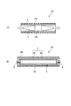
- FIG. 1 is a sectional view showing an embodiment of the contact pressure roll according to the present invention.
- 2 (a) and 2 (b) are a side view and a perspective view, respectively, for explaining one embodiment of the outer cylinder side end surface member of the contact pressure roll according to the present invention.
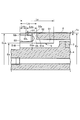
- FIGS. 3A and 3B are detailed partial cross-sectional views for explaining one embodiment of the outer cylinder side end surface member of the contact pressure roll according to the present invention.
- FIGS. 4A and 4B are perspective views illustrating one embodiment of a method for manufacturing the outer cylinder member and the inner cylinder member of the contact pressure roll according to the present invention.
- FIG. 5 (a) is a perspective view of a pressure contact roll assembly assembled to form a plating layer on the pressure contact roll according to the present invention
- FIG. 5 (b) is an embodiment of a plating method.
- FIGS. 6A and 6B are cross-sectional views illustrating an example of a conventional contact pressure roll.
- the contact pressure roll of the present invention is described as a contact pressure roll for winding a film while pressing against a film product being wound in a film winding device such as a slitter or a winder.
- the contact pressure roll is not limited to these applications.For example, in addition, it can also be used as a film laminating roll, a nip, a press roll, etc. Can be used.
- FIG. 1 and FIG. 2 show an embodiment of a contact pressure roll according to the present invention.
- the contact pressure roll 1 includes a cylindrical outer cylinder member 2 and an inner cylinder member 3 located inside the outer cylinder member 2 and arranged on the same axis as the outer cylinder member 2.
- the outer cylinder member 2 is integrally connected at a joint 3 ⁇ / b> A formed at the axial center of the inner cylinder member 3.
- the outer cylinder member 2 has a metal plating layer 6 formed on the outer peripheral surface thereof.
- the inner cylindrical member 3 includes a rotating shaft member 4 at the same axial line at both ends in the axial direction, and the rotating shaft member 4 includes, via a bearing 8, an arm member or the like of a film winding device that supports a contact pressure roll.
- the contact pressure roll 1 will be described as a contact pressure roll for winding a film in a film winding device, but its overall shape has a diameter (outer diameter D2) of 40 to 450 mm and a longitudinal direction ( A variety of shapes are manufactured within a length L2 of 500 to 7000 mm in the axial direction). More specifically, from a small roll having a diameter (D2) ⁇ length (L2) of 40 mm ⁇ 500 mm to a large roll having a diameter (D2) ⁇ length (L2) of 450 mm ⁇ 7000 mm, high surface properties and It can be manufactured with high accuracy.
- the outer cylinder member 2 has a cylindrical shape having a length L2 in the longitudinal direction, an outer diameter D2, and a thickness T2, and is made of carbon fiber reinforced resin.
- the outer diameter D2 of the outer cylindrical member 2 is 40 to 450 mm
- the length L2 in the direction (axial direction) is set to 500 to 7000 mm
- the thickness T2 can be formed in various sizes within a range of 3 to 20 mm according to the application.
- the inner cylindrical member 3 disposed inside the outer cylindrical member 2 has a cylindrical shape extending in the longitudinal direction by a length L3 (L3 ⁇ L2) on the same axis as the outer cylindrical member 2, and the present embodiment.
- the length is shortened on one side of the outer cylinder member 2 by a length L23 (2 ⁇ L23 in total length).
- the inner cylinder member 3 is expanded in width (length L3A) at a central portion to form a joint 3A with the outer cylinder member 2. Therefore, the inner peripheral surface of the outer cylinder member 2 and the outer peripheral surface of the inner cylinder member 3 are integrally fixed by bonding or press-fitting at the joint 3A.
- the thickness T3b of the reduced diameter portion 3B extending on both sides of the joint 3A is larger than the thickness T3a of the joint 3A joined to the outer cylinder member 2 with the inner surface of the outer cylinder member 2.
- the gap G between the outer surface of the tubular member 3 and the outer surface is reduced.
- the interval G is usually about 1 to 50 mm, though it depends on the size of the contact pressure roll. That is, in the present embodiment, the outer cylinder member 2 and the inner cylinder member 3 are separated from each other by a predetermined distance G on both sides of the joint 3A in the axial direction. Form a double tube structure joined only at the joint 3A.
- the inner cylinder member 3 can be made of a metal such as stainless steel or aluminum, but can be made of a fiber-reinforced resin in terms of weight reduction and rigidity. It is preferable to use a carbon fiber reinforced resin. In the present embodiment, description will be made assuming that the inner cylindrical member 3 is also made of carbon fiber reinforced resin.
- a rotating shaft member 4 is provided at both ends in the longitudinal direction of the inner cylindrical member 3 along the same axis.
- the rotating shaft member 4 includes a cylindrical member supporting portion 41 fixed to the inner surface of the end portion of the inner cylindrical member 3 and a rotating shaft portion 42 coaxially extending from the supporting portion 41 and extending outward of the inner cylindrical member 3.
- a flange 43 is formed between the support portion 41 and the rotation shaft portion 42, and abuts on the annular end surface of the inner cylindrical member 3.
- the outer diameter of the flange 43 is substantially the same as the outer diameter of the reduced diameter portion 3B of the inner cylinder member 3, and the thickness L43 is approximately 5 mm.
- the rotation shaft portion 42 is not limited, but in the present embodiment, the shaft portions 42a (outer diameter D42a) and 42b (outer diameter) sequentially reduced outward in a direction opposite to the support portion 41.
- the bearing 8 is formed with diameters D42b) and 42c (outer diameter D42c), and the bearing 8 is attached to the shaft portion 42c at the tip with the washer 9 and the fixing screw 10.
- the bearing 8 is supported by a housing 11 such as an arm of the winding device main body. When the arm is operated, the contact pressure roll 1 is pressed at a predetermined pressure against the film product, and is rotated by the movement of the film. It will be.
- the contact pressure roll 1 of the present invention includes, at both ends in the longitudinal direction of the outer cylinder member 2, an outer cylinder side end face member 5 having a stepped cylindrical shape integrally fixed along the same axis as the outer cylinder member 2. ing.
- the outer tube side end member 5 functions as a plating electrode when the metal plating layer 6 is formed on the surface of the outer tube member 2, which will be described in detail later, and further adjusts the imbalance of the contact pressure roll 1.
- the outer cylinder side end member 5 is made of metal such as stainless steel and aluminum.
- the outer cylinder side end surface member 5 is a cylindrical sleeve-shaped support portion 51 fixed to the inner surface of the end portion of the outer cylinder member 2, and the outer cylinder member 2 is disposed outside the outer cylinder member 2 on the same axis from the support portion 51.
- a cylindrical side plate 52 extending in a cylindrical shape.
- the size (inner diameter D5) of the inner surface of the cylindrical sleeve-shaped support portion 51 is a size that allows the rotation shaft portion 42 of the rotation shaft member 4 attached to the inner cylinder member 3 to penetrate. That is, in the present embodiment, the size (inner diameter D5) of the inner surface of the cylindrical sleeve-shaped support portion 51 is larger than the outer peripheral surfaces (outer diameters D42a to 42c) of the rotating shaft portions 42a to 42c of the rotating shaft member 4. (D5> D42a to 42c).
- the outer diameter (D52) of the cylindrical side plate 52 is the same as the outer diameter (D2) of the outer cylinder member 2 so as to form the same cylindrical surface as the outer peripheral surface of the outer cylinder member 2. Therefore, the annular shoulder end surface 51A formed by the side plate 52 and the support portion 51 is in contact with the side annular end surface 2A of the outer cylinder member 2, and the outer periphery at the joint position between the outer cylinder member 2 and the cylindrical side plate 52 is formed. On the surface, the same circumferential surface having no step is formed.
- the cylindrical side plate 52 of the outer cylindrical side end surface member 5 is provided with an outer cylindrical member on the outer end surface 51B opposite to the support portion 51.
- a plurality of screw holes 53 are formed at the same radius R53 from the axis center O5 of the side plate 52 of the outer cylinder side end surface member 5 coaxial with 2.
- the outer diameter D52 of the side plate 52 that is, the outer diameter D2 of the outer cylinder member 2 is 49.4 mm
- the inner diameter D5 is 32 mm
- the axial length L52 of the side plate 52 is 15 mm.
- a tap of M6 was formed at a depth of 10 mm (a prepared hole depth of 13 mm) on the same circumference having a radius R53 of 20 mm (diameter of 40 mm).
- 16 screw holes 53 are formed on the outer end surface 51B of the cylindrical side plate 52 at equal circumferential intervals.
- the size and number of the screw holes 53 are not limited thereto. It is appropriately selected according to the size of the pressure roll.
- plating electrodes for forming the plating layer 6 on the outer tubular member 2 are provided. Further, when adjusting the unbalance amount of the manufactured pressure roller 1, a plurality of types of male screw weights having a weight of 1 g, 0.5 g, or the like are used as the balance weight using the screw holes 53. The balance can be adjusted by appropriately screwing it to a designated adjustment location. According to the present invention, it is possible to adjust the imbalance from both sides in the longitudinal direction of the contact pressure roll 1, and it is possible to adjust the rotational deflection accuracy of the contact pressure roll 1.
- the cylindrical side plate 52 of the outer cylinder side end member 5 can be formed in a stepped cylindrical shape, and the large diameter portion 52a (outside A diameter D52a) and a small diameter portion 52b (outer diameter D52b) extending from the large diameter portion 52a in a direction away from the end surface 2A of the outer cylindrical member 2.
- the outer diameter difference between the large diameter portion 52a and the small diameter portion 52b, that is, the step ⁇ E (1 /) ⁇ (D52a ⁇ D52b) is set to 0.1 to 10 mm, usually about 0.5 mm.
- the plating layer 6 is formed on the outer cylinder member surface by providing the step ⁇ E on the outer peripheral surface of the side plate of the outer cylinder side end member 5, the plating layer 6 is connected to the outer cylinder section surface. It is also formed on the outer peripheral surface of the side plates 52a and 52b of the outer cylinder side end member 5.
- the plating layer 6 formed on the outer peripheral surface of the pressure roller 1 has a step ⁇ E at both ends in the longitudinal direction of the pressure roller 1, that is, the outer peripheral surface of the outer end 52 b of the cylindrical side plate 52. The diameter is reduced. Accordingly, the plating layer 6 is completely prevented from moving or dropping off from the contact pressure roll 1 in the axial direction.
- a cylindrical body (hereinafter, referred to as a “CFRP cylindrical body”) using carbon fiber reinforced resin, which is an outer cylindrical member and an inner cylindrical member, can be formed by a filament winding method or a sheet winding method known to those skilled in the art. Although it can be suitably manufactured by using, the molding method is not limited to these methods.
- the CFRP cylindrical body 2 for the outer cylinder member is manufactured by the filament winding method
- the carbon fiber f is wound around the mandrel 100 using a predetermined resin to form the carbon fiber layer 20 for the CFRP cylindrical body 2M.
- the resin impregnated in the carbon fiber can be a thermosetting resin or a thermoplastic resin, or a mixed resin of a thermosetting resin and a thermoplastic resin.
- a thermosetting resin a room temperature or thermosetting epoxy resin, a vinyl ester resin, an MMA resin, an acrylic resin, an unsaturated polyester resin, a phenol resin, or the like is preferably used.
- Nylon, vinylon and the like can be suitably used.
- the amount of the resin with respect to the carbon fiber is 30 to 70% by weight, preferably 40 to 60% by weight.
- the carbon fiber layer 20 can be composed of a plurality of layers, for example, first to n-th carbon fiber layers 20a, 20b,... 20n, and each of the carbon fiber layers 20a, 20b,. Can make the winding angle ( ⁇ ) of the fiber f with respect to the axis of the cylindrical body different from each other.
- the CFRP cylinder 2M obtained as described above after removing the tape is polished to adjust the diameter of the cylinder to a predetermined size.
- the surface roughness Ra of the cylindrical body after the polishing treatment is 0.8 to 15 ⁇ m, preferably 2 to 8 ⁇ m.
- the sheet winding method is carried out in the same manner as the above-mentioned filament winding method except that a sheet-like carbon fiber prepreg is used.
- a CFRP cylindrical body is manufactured by a sheet winding method, as described with reference to FIG. 4A, first, a carbon layer is formed on the mandrel 100 in a predetermined lamination configuration to obtain a predetermined thickness.
- the fiber prepreg 20 (20a, 20b,..., 20n) is wound with a predetermined fiber orientation.
- the CFRP cylinder obtained as described above after removing the tape is polished to adjust the diameter of the cylinder to a predetermined size in the same manner as in the filament winding method.
- the surface roughness Ra of the cylindrical body after the polishing treatment is 0.8 to 15 ⁇ m, preferably 2 to 8 ⁇ m.
- the inner cylindrical member 3 can be manufactured in the same manner as the outer cylindrical member. However, as shown in FIG. 4B, when the inner cylindrical member 3 is manufactured using the filament winding method or the sheet winding method, CFRP is used. The difference is that a joint 3A having an enlarged diameter is formed at the center of the cylindrical body 3M. Also, in the CFRP cylindrical body 3M of the inner cylindrical member, the entire outer peripheral surface is polished and adjusted to a predetermined size.
- the surface roughness Ra of the cylindrical body after the polishing treatment is 0.8 to 15 ⁇ m, preferably 2 to 8 ⁇ m. However, in some cases, the polishing process may be performed with high accuracy only on the joint 3A.
- the inner cylinder member 3 may be made of another fiber reinforced resin instead of the carbon fiber reinforced resin.
- the reinforcing fibers inorganic fibers such as glass fibers, metal fibers such as steel fibers, and further, organic fibers such as aramid fibers or the like may be used alone, or may be mixed and used in a hybrid form. Can be.
- the resin impregnated in the reinforcing fibers and the impregnation amount may be the same as the resin impregnated in the carbon fibers and the impregnation amount.
- the CFRP cylinders 2M and 3M produced as described above are cut at a predetermined length to produce the outer cylinder member 2 and the inner cylinder member 3.
- the cylindrical support portion 41 of the rotary shaft member 4 is integrally fixed to the inner cylindrical member 3 by bonding or press-fitting the cylindrical inner surfaces at both ends, that is, the mounting holes.
- the outer cylinder member 2 is inserted outside the inner cylinder member 3 in which the rotary shaft member 4 is integrated, and is bonded or press-fitted to the joint 3A of the inner cylinder member 3 to be integrally joined.
- the cylindrical support portions 41 of the rotary shaft member 4 are bonded or press-fitted to the cylindrical inner surfaces at both ends of the inner tube member 3. They can be fitted and fixed integrally.
- the cylindrical support portions 51 of the outer tube side end member 5 are fitted to the cylindrical inner surfaces at both ends of the outer tube member 2, and preferably at least the side plate 52 is A contact pressure roll assembly 1P is manufactured by tightly fixing the shoulder end surface 51A and the side annular end surface 2A of the outer cylindrical member 2 in close contact with each other via a conductive adhesive.
- the contact pressure roll assembly 1P manufactured as described above is placed in a plating tank 201 of a plating apparatus 200 as shown in FIG. 5B, and the outer peripheral surface of the contact pressure roll 1 is subjected to plating.
- the plating layer 6 is formed.
- the cathode electrode jig 203 as a plating electrode is screwed using the screw holes 53 formed in the cylindrical side plate 52 of the outer cylinder side end surface member 5 on both sides of the contact pressure roll assembly 1P. At 208, it is fixed.
- the cathode electrode jig 203 is a cylindrical body 204 having an opening at one end and a recess closed at the other end by a wall member 205.
- the outer diameter of the cylindrical body 204 of the cathode electrode jig 203 is the same as the outer diameter of the cylindrical side plate 52, the inner diameter is substantially the same as the inner diameter of the cylindrical side plate 52, and the rotary shaft member 4 is included in the cylindrical body recess.
- the cathode electrode jig 203 penetrates the cylindrical body 204 portion, and the cylindrical member 204 of the outer cylinder side end face member 5 is screwed through, for example, four through holes 207 formed at equal intervals in the circumference. It is fixed to the side plate 52.
- the cathode electrode jig 203 is provided with the plating solution except for the plating layer forming portion of the contact pressure roll assembly 1P, that is, in this embodiment, the outer peripheral surface of the outer cylinder member 2 and the outer peripheral surface of the cylindrical side plate 52. It also functions as a masking material to prevent adhesion.
- the cathode electrode jig 203 has a cathode electrode mounting shaft 206 formed to protrude outward from the wall member 205, and is connected to a power supply of the plating apparatus 200 via a conductive wire 202, and supplied with current.
- At least the entire surface of the annular end surface region of the end surface 2A of the outer cylinder member 2 serves as the power supply surface. That is, current is supplied to the outer cylinder member 2 from the entire annular end surface area of the annular shoulder end surface 51A of the cylindrical side plate 52 of the outer cylinder side end member 5 via the annular end surface 2A of the outer cylinder member 2.
- the outermost resin layer is removed from the entire surface of the outer cylinder member 2 by the polishing treatment, so that the carbon fibers are exposed.
- the density of the current flowing on the entire surface of the outer cylindrical member 2 is made uniform, and a uniform plating layer can be formed.
- hard chromium (Hcr) plating having a hardness of 800 or more in Vickers hardness (HV) and a low friction coefficient and excellent wear resistance is preferred as metal plating.
- HV Vickers hardness
- hard chromium (Hcr) plating has a property that it is difficult to form plating directly on carbon fiber reinforced resin. Therefore, it is preferable that the plating layer has a multilayer structure of two or more layers, and it is preferable to provide an underlayer and further an intermediate layer.
- the plating thickness of the plating layer is not particularly limited, but is generally 200 to 1000 ⁇ m for the underlayer (Ni or Cu plating layer) and 10 to 150 ⁇ m for the surface layer (Hcr plating layer).
- the underlayer (Cu plating layer) is 200 to 1000 ⁇ m
- the intermediate layer (Ni plating layer) is 20 to 200 ⁇ m
- the surface layer (Hcr plating layer) is 10 to 150 ⁇ m.
- the contact pressure roll assembly 1P in which the plating layer 6 is formed on the outer cylinder member 2 as described above is then subjected to surface polishing and finishing by buff polishing or the like.
- the surface roughness (Ry) of the outer cylindrical member 2 of the contact pressure roller having the surface hardness (HV) of 800 or more can be finished to be 0.2 ⁇ m or less.
- the contact pressure roller assembly manufactured as described above is set on a balancer (balance adjusting device), the unbalance amount is measured, and the contact pressure roller assembly is integrally set on the side surface of the contact pressure roller assembly.
- a balancer balance adjusting device
- the unbalance amount of the contact pressure roll 1 could be reduced to 2 g / 3000 rpm or less on one side of the dynamic balance.
- the accuracy (rotational runout) of the contact pressure roll after performing the balance adjustment could be processed to 0.02 mm or less. That is, it was possible to obtain a roller having extremely high rotational runout accuracy as compared with a conventional roll.
- One of the features of the contact pressure roll 1 of the present invention is that when the plating layer 6 on the surface of the outer cylinder member 2 is worn, the plating layer 6 is formed by a chemical method or an electrochemical method known to those skilled in the art. Is peeled off from the outer cylinder member, and replating is enabled.
- hollow tubes 2M and 3M made of carbon fiber reinforced resin used as the outer tube member 2 and the inner tube member 3 were produced by a filament winding method.
- the carbon fiber f as the reinforcing fiber of the carbon fiber reinforced resin, a fiber bundle having an average monofilament diameter of 7 ⁇ m and a converging number of 12,000, that is, a PAN-based carbon fiber strand (“TR50” (trade name) manufactured by Mitsubishi Rayon Co., Ltd.) is used.
- the epoxy resin (“HP100” manufactured by Nippon Steel & Sumikin Materials Co., Ltd.) was used as the resin.
- the outermost layer 20n of the carbon fiber layer 20 was wound around the fiber f at an angle ( ⁇ ) of 45 ° in the same direction.
- the mandrel 100 around which the carbon fiber layer 20 impregnated with the resin was wound was charged into a heat-curing furnace, and the resin was cured. . Thereafter, the cured carbon fiber reinforced resin molded products (hollow tubes) 2M and 3M were removed from the mandrel 100, and the CFRP hollow tubes 2M and 3M removed from the mandrel 100 were polished.
- the surface roughness Ra of the hollow tubes 2M and 3M after the polishing treatment was 6 ⁇ m.
- the contact pressure roll 1 thus manufactured had the following dimensions and shape.
- (Outer cylinder member 2) Material: Carbon fiber reinforced resin Outer diameter (D2) x length (L2): 49.4 mm x 1070 mm Layer thickness (T2): 5.7 mm (Plating layer 6) Underlayer plating (Ni plating) thickness: 0.25mm Surface plating (Hcr) thickness: 0.05mm (Inner cylinder member 3) Material: Carbon fiber reinforced resin Outer diameter (D3) x Length (L3): 38mm (joint) x 1020mm Joint layer thickness (T3a): 7 mm Layer thickness (T3b) on both sides of the joint: 5.5 mm (Outer cylinder side end member 5) Material: Stainless steel (SUS420j2) Inner diameter (D5) x length (L5): 32 mm x 30 mm Outer diameter (D52a) x length (L52a) of side plate large diameter portion: 49.4 mm x 10 mm Outer diameter (D52b) x length (L52b) of side plate small diameter portion: 48.9 mm
- the surface hardness of the outer cylindrical member of the surface-finished contact pressure roller 1 manufactured in this manner was 800 or more in HV, and the surface roughness (Ry) was 0.2 ⁇ m.
- the accuracy (roundness, cylindricity, run-out) of the contact pressure roll 1 after the balance adjustment was 0.02 mm or less.
- the rotational runout was 0.02 mm at 3000 rpm.
- the contact pressure roll 1 manufactured as described above can easily achieve a satin finish as needed.
- the plating layer 6 of the contact pressure roll manufactured according to the present invention can be peeled off from the outer cylinder member by a chemical method or an electrochemical method. Is possible.
Landscapes
- Chemical & Material Sciences (AREA)
- Engineering & Computer Science (AREA)
- Chemical Kinetics & Catalysis (AREA)
- Electrochemistry (AREA)
- Materials Engineering (AREA)
- Metallurgy (AREA)
- Organic Chemistry (AREA)
- General Engineering & Computer Science (AREA)
- Mechanical Engineering (AREA)
- Rolls And Other Rotary Bodies (AREA)
- Advancing Webs (AREA)
- Registering, Tensioning, Guiding Webs, And Rollers Therefor (AREA)
- Electroplating Methods And Accessories (AREA)
Abstract
L'invention concerne un rouleau de contact à pression à structure de double tuyau présentant un élément de tube externe composé d'au moins une résine renforcée par des fibres de carbone, le rouleau de contact à pression étant configuré de sorte qu'une couche de placage métallique est uniformément et fermement liée à la surface de l'élément de tube externe, le rouleau de contact à pression présentant une excellente aptitude au façonnage telle qu'un lissé et un matage, ce qui permet en particulier de supprimer une vibration de rotation à une valeur faible, et présentant une résistance à l'abrasion élevée. Un rouleau de contact à pression à structure de double tuyau présente un élément de tube externe cylindrique (2) composé d'une résine renforcée par des fibres de carbone, et un élément de tube interne (3) disposé de façon coaxiale avec l'élément de tube externe sur le côté interne de l'élément de tube externe, l'élément de tube externe (2) est accouplé d'un seul tenant à une partie de jonction (3A) formée sur la partie centrale de direction axiale de l'élément de tube interne, l'élément de tube interne présentant un élément d'arbre rotatif (4) qui est fixé de façon coaxiale et d'un seul tenant à l'élément de tube interne au niveau de ses deux parties d'extrémité de direction axiale, et une couche de placage métallique (6) étant formée sur la surface périphérique externe de l'élément de tube externe, des éléments de surface d'extrémité côté tube externe (5) composés de métal étant fixés d'un seul tenant à chacune des deux parties d'extrémité de direction axiale de l'élément de tube externe, les éléments de surface d'extrémité côté tube externe étant destinés à fixer des électrodes de placage pendant la formation de la couche de placage métallique.
Applications Claiming Priority (2)
| Application Number | Priority Date | Filing Date | Title |
|---|---|---|---|
| JP2018129183A JP7169105B2 (ja) | 2018-07-06 | 2018-07-06 | 接圧ロール |
| JP2018-129183 | 2018-07-06 |
Publications (1)
| Publication Number | Publication Date |
|---|---|
| WO2020009161A1 true WO2020009161A1 (fr) | 2020-01-09 |
Family
ID=69060846
Family Applications (1)
| Application Number | Title | Priority Date | Filing Date |
|---|---|---|---|
| PCT/JP2019/026503 Ceased WO2020009161A1 (fr) | 2018-07-06 | 2019-07-03 | Rouleau de contact à pression |
Country Status (3)
| Country | Link |
|---|---|
| JP (1) | JP7169105B2 (fr) |
| TW (1) | TW202005896A (fr) |
| WO (1) | WO2020009161A1 (fr) |
Families Citing this family (1)
| Publication number | Priority date | Publication date | Assignee | Title |
|---|---|---|---|---|
| JP7047169B1 (ja) * | 2021-06-11 | 2022-04-04 | 三菱ケミカル株式会社 | ロールの製造方法及びロール |
Citations (5)
| Publication number | Priority date | Publication date | Assignee | Title |
|---|---|---|---|---|
| JPS62177313A (ja) * | 1986-01-30 | 1987-08-04 | Mitsubishi Rayon Co Ltd | ロ−ラ− |
| JPH0211914A (ja) * | 1988-06-30 | 1990-01-17 | Mitsubishi Heavy Ind Ltd | ローラの製造方法 |
| JPH06328593A (ja) * | 1993-05-21 | 1994-11-29 | Petoca:Kk | 繊維強化樹脂製ロールの製造方法 |
| JP2004204357A (ja) * | 2004-03-26 | 2004-07-22 | Mitsubishi Rayon Co Ltd | メタルコートロール |
| JP6009328B2 (ja) * | 2012-11-15 | 2016-10-19 | Jxエネルギー株式会社 | 接圧ロール及びその製造方法 |
-
2018
- 2018-07-06 JP JP2018129183A patent/JP7169105B2/ja active Active
-
2019
- 2019-07-03 WO PCT/JP2019/026503 patent/WO2020009161A1/fr not_active Ceased
- 2019-07-05 TW TW108123798A patent/TW202005896A/zh unknown
Patent Citations (5)
| Publication number | Priority date | Publication date | Assignee | Title |
|---|---|---|---|---|
| JPS62177313A (ja) * | 1986-01-30 | 1987-08-04 | Mitsubishi Rayon Co Ltd | ロ−ラ− |
| JPH0211914A (ja) * | 1988-06-30 | 1990-01-17 | Mitsubishi Heavy Ind Ltd | ローラの製造方法 |
| JPH06328593A (ja) * | 1993-05-21 | 1994-11-29 | Petoca:Kk | 繊維強化樹脂製ロールの製造方法 |
| JP2004204357A (ja) * | 2004-03-26 | 2004-07-22 | Mitsubishi Rayon Co Ltd | メタルコートロール |
| JP6009328B2 (ja) * | 2012-11-15 | 2016-10-19 | Jxエネルギー株式会社 | 接圧ロール及びその製造方法 |
Also Published As
| Publication number | Publication date |
|---|---|
| TW202005896A (zh) | 2020-02-01 |
| JP7169105B2 (ja) | 2022-11-10 |
| JP2020007605A (ja) | 2020-01-16 |
Similar Documents
| Publication | Publication Date | Title |
|---|---|---|
| US5061533A (en) | Roll formed of carbon fiber composite material | |
| US9413199B2 (en) | Rotor of electric motor with magnet holding structure and electric motor including the rotor | |
| US20170102019A1 (en) | Struts and methods utilizing a locking collar nut | |
| KR20220093201A (ko) | 스플릿 베어링, 조립체 및 이의 제조 및 사용 방법 | |
| WO2020009161A1 (fr) | Rouleau de contact à pression | |
| CN104661943A (zh) | 薄膜卷用芯、薄膜卷、薄膜卷的制造方法及薄膜的卷取装置 | |
| US4677721A (en) | Method for fabricating an elastomeric bearing assembly | |
| JP5423017B2 (ja) | ロール及びその製造方法 | |
| US4585359A (en) | Bearing assembly | |
| JP2004204357A (ja) | メタルコートロール | |
| JPH068354A (ja) | 繊維強化樹脂製ロールおよびその製造方法 | |
| JP3221124B2 (ja) | 金属被覆繊維強化プラスチック製ロール | |
| US9464685B2 (en) | Composite dome connectors for flywheel rim to shaft attachment | |
| US20200028280A1 (en) | Cylindrical member and structure using cylindrical member | |
| JP6193431B2 (ja) | 耐熱用繊維強化プラスチックロール | |
| JP6312491B2 (ja) | ウェブ製造用ロール | |
| JPS63249628A (ja) | 繊維強化樹脂製筒状体 | |
| JP7193645B2 (ja) | トレランスリング、アセンブリ、ならびにその作製および使用方法 | |
| JP4390114B2 (ja) | 印刷原版支持用のドラム | |
| JP2005040963A (ja) | 巻き取りコア | |
| JP7001431B2 (ja) | 二重管ロール | |
| CA2133660A1 (fr) | Rouleau revetu de metal, constitue de resine renforcee de fibres; methode de preparation | |
| JP2521341B2 (ja) | ロ―ル | |
| JPH09205943A (ja) | 釣 竿 | |
| JP5912057B2 (ja) | 耐熱用繊維強化プラスチックロール |
Legal Events
| Date | Code | Title | Description |
|---|---|---|---|
| 121 | Ep: the epo has been informed by wipo that ep was designated in this application |
Ref document number: 19830407 Country of ref document: EP Kind code of ref document: A1 |
|
| NENP | Non-entry into the national phase |
Ref country code: DE |
|
| 122 | Ep: pct application non-entry in european phase |
Ref document number: 19830407 Country of ref document: EP Kind code of ref document: A1 |