WO2020009172A1 - Caméra - Google Patents
Caméra Download PDFInfo
- Publication number
- WO2020009172A1 WO2020009172A1 PCT/JP2019/026541 JP2019026541W WO2020009172A1 WO 2020009172 A1 WO2020009172 A1 WO 2020009172A1 JP 2019026541 W JP2019026541 W JP 2019026541W WO 2020009172 A1 WO2020009172 A1 WO 2020009172A1
- Authority
- WO
- WIPO (PCT)
- Prior art keywords
- imaging
- image
- base line
- line length
- optical system
- Prior art date
- Legal status (The legal status is an assumption and is not a legal conclusion. Google has not performed a legal analysis and makes no representation as to the accuracy of the status listed.)
- Ceased
Links
Images


Classifications
-
- H—ELECTRICITY
- H04—ELECTRIC COMMUNICATION TECHNIQUE
- H04N—PICTORIAL COMMUNICATION, e.g. TELEVISION
- H04N23/00—Cameras or camera modules comprising electronic image sensors; Control thereof
-
- G—PHYSICS
- G01—MEASURING; TESTING
- G01C—MEASURING DISTANCES, LEVELS OR BEARINGS; SURVEYING; NAVIGATION; GYROSCOPIC INSTRUMENTS; PHOTOGRAMMETRY OR VIDEOGRAMMETRY
- G01C3/00—Measuring distances in line of sight; Optical rangefinders
- G01C3/02—Details
- G01C3/06—Use of electric means to obtain final indication
Definitions
- the present technology relates to a camera, and more particularly, to a camera that can capture a stereo image.
- Patent Document 1 describes a camera that captures a stereo image (left-eye image and right-eye image) with a configuration having a single image sensor.
- Japanese Patent Application Laid-Open No. H11-163873 discloses that when capturing a stereo image (a left-eye image and a right-eye image) with a configuration having a single image sensor, the left-eye image and the right-eye image are captured in different areas on the imaging surface of the image sensor. Is described.
- the distance can be obtained with higher resolution as the base line length when capturing a stereo image is longer, and furthermore, when the base line length is made longer, the common area of the left eye image and the right eye image Is narrowed, and parallax cannot be obtained in a short-distance area (for example, see Patent Document 3).
- the purpose of the present technology is to make it possible to obtain distance with high resolution and obtain parallax in a short-distance region.
- the concept of this technology is An image sensor; A first imaging optical system that forms a left-eye image according to a first base line length on a first region of an imaging surface of the imaging element; A second imaging optical system that forms a right-eye image corresponding to the first base line length on a second region of an imaging surface of the imaging element; A third imaging optical system that forms a left-eye image according to a second baseline length shorter than the first baseline length on a third region of the imaging surface of the imaging element; The camera includes a fourth imaging optical system that forms a right-eye image according to the second base line length on a fourth region of an imaging surface of the imaging element.
- the camera includes an imaging element and first to fourth imaging optical systems.
- the first imaging optical system forms an image of the left eye corresponding to the first base line length in a first region of the imaging surface of the imaging device
- the second imaging optical system forms a second image of the imaging surface of the imaging device.
- the right eye image according to the first base line length is formed in the region of.
- the third imaging optical system forms an image of the left eye corresponding to the second base line length in a third region of the imaging surface of the imaging device
- the fourth imaging optical system forms an image of the imaging surface of the imaging device.
- the right eye image according to the second base line length is formed in the fourth area.
- the second base line length is shorter than the first base line length.
- each of the first to fourth imaging optical systems may include a rhomboid prism.
- the rhomboid prisms included in the first to fourth imaging optical systems are arranged such that the emission surfaces are in contact with the first to fourth regions of the imaging surface of the imaging device. You may be.
- a light-blocking member may be provided in an outer surface area corresponding to at least the reflection surface on the emission surface side of each of the rhomboid prisms included in the first to fourth imaging optical systems.
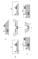
- the first to fourth regions of the imaging surface of the imaging device may be regions obtained by dividing the imaging surface into a cross-shaped shape.
- a stereo image (a left-eye image and a right-eye image) when the base line length is relatively long is obtained by imaging using the first region and the second region of the imaging surface of the imaging device.
- the distance can be obtained with high resolution
- a stereo image (left-eye image) when the base line length is relatively short by imaging with the third and fourth regions of the imaging surface of the imaging device , Right-eye image).
- the common area of the left-eye image and the right-eye image is widened, and it is possible to obtain parallax in a short-distance area.
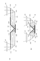
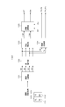
- FIG. 3 is a diagram for explaining an optical path and the like in each of first to fourth imaging optical systems. It is a figure which shows the width
- FIG. 4 is a block diagram illustrating a configuration example of a processing unit that performs an object recognition process and a distance measurement process to a recognized object in an image processing circuit.
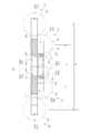
- Embodiment> [camera] 1 and 2 show a configuration example of a camera 10 as an embodiment.
- FIG. 1 is a schematic perspective view of the camera 10
- FIG. 2 is a schematic front view of the camera 10.
- the camera 10 includes the imaging element 11, the first imaging optical system 21, the second imaging optical system 22, the third imaging optical system 23, and the fourth imaging optical system 24.
- the image sensor (imager) 11 is an individual image sensor such as a CCD (Charged-coupled devices) image sensor or a CMOS (Complementary metal-oxide-semiconductor) image sensor.
- the image pickup device 11 has its image pickup surface 111 divided into a plurality of regions, and different images are picked up in the respective regions.
- the imaging surface 111 is divided into a first area 111a, a second area 111b, a third area 111c, and a fourth area 111d in a cross-shaped manner, and these four areas are different from each other. Images are taken simultaneously.
- the first imaging optical system 21 includes an imaging lens 211 and a rhomboid prism (rhombic prism) 212.
- the rhomboid prism 212 is arranged such that its emission surface 212b contacts the first area 111a of the imaging surface 111 of the imaging device 11.
- the imaging lens 211 is arranged at a position facing the incident surface 212a of the rhomboid prism 212.
- a light shielding member 213 is provided at least on the outer surface area of the reflection surface 212d corresponding to the emission surface 212b of the rhomboid prism 212.
- the light-blocking member 213 is provided on the rhomboid prism 212 by attaching a light-blocking sheet or applying a light-blocking paint.
- the reason why the light shielding member 213 is provided in this way is to suppress the influence of light incident from the outer surface region. The same applies to the light-blocking members provided in other rhomboid prisms described below.
- the second imaging optical system 22 includes an imaging lens 221 and a rhomboid prism (rhombic prism) 222.
- the rhomboid prism 222 is arranged such that its emission surface 222b is in contact with the second region 111b of the imaging surface 111 of the imaging device 11.
- the rhomboid prism 222 is continuous with the above-described rhomboid prism 212 of the first imaging optical system 21 on the same straight line.
- the imaging lens 221 is arranged at a position facing the incident surface 222a of the rhomboid prism 222.
- a light-blocking member 223 is provided at least on the outer surface area of the reflection surface 222d corresponding to the emission surface 222b of the rhomboid prism 222.
- the first imaging optical system 21 forms the left-eye image corresponding to the first base line length L1 on the first area 111a of the imaging surface 111 of the imaging element 11.
- the light from the subject incident on the imaging lens 211 is incident from the incident surface 212a of the rhomboid prism 212, is reflected by the reflecting surface 212c, and is thereafter reflected by the reflecting surface 212c.
- the light is reflected from the emission surface 212d, is emitted from the emission surface 212b, reaches the first region 111a of the imaging surface 111 of the imaging device 11, and forms a left-eye image corresponding to the first base line length L1 on the first region 111a. Imaged.
- the second imaging optical system 22 forms the right-eye image according to the first base line length L1 on the second area 111b of the imaging surface 111 of the imaging element 11.
- the light from the subject incident on the imaging lens 221 is incident from the incident surface 222a of the rhomboid prism 222, is reflected on the reflecting surface 222c, and is thereafter reflected by the reflecting surface 222c.
- the light is reflected at 222d, is emitted from the emission surface 222b, reaches the second region 111b of the imaging surface 111 of the imaging device 11, and the right eye image according to the first base line length L1 is formed on the second region 111b. Imaged.
- the first base line length L1 is the distance between the optical axes of the imaging lenses 211 and 221 as shown in FIG.
- the first base length L1 is determined by the lengths of the Lomboid prism 212 of the first imaging optical system 21 and the Lomboid prism 222 of the second imaging optical system 22.
- the first base line length L1 can be adjusted by changing the lengths of the Lomboid prism 212 of the first imaging optical system 21 and the Lomboid prism 222 of the second imaging optical system 22.
- the third imaging optical system 23 includes an imaging lens 231 and a rhomboid prism (rhombic prism) 232.
- the rhomboid prism 232 is arranged such that its emission surface 232b contacts the third region 111c of the imaging surface 111 of the imaging device 11. In this case, the rhomboid prism 232 is in a state of being arranged adjacent to the above-described rhomboid prism 212 of the first imaging optical system 21.
- the imaging lens 231 is arranged at a position facing the entrance surface 232a of the rhomboid prism 232.
- a light-blocking member 233 is provided on at least the outer surface area of the reflection surface 232d corresponding to the emission surface 232b of the rhomboid prism 232.
- the fourth imaging optical system 24 includes an imaging lens 241 and a rhomboid prism (rhombic prism) 242.
- the rhomboid prism 242 is arranged such that its emission surface 242b contacts the fourth region 111d of the imaging surface 111 of the imaging device 11.
- the rhomboid prism 242 becomes continuous with the above-described rhomboid prism 232 of the third imaging optical system 23 on the same straight line, and the rhomboid prism 222 of the second imaging optical system 22 described above. And a state in which they are adjacent to each other.
- the imaging lens 241 is disposed at a position facing the incident surface 242a of the rhomboid prism 242.
- a light-blocking member 243 is provided at least on the outer surface area of the reflection surface 242d corresponding to the emission surface 242b of the rhomboid prism 242.
- the third imaging optical system 23 forms the left-eye image corresponding to the second base line length L2 on the third area 111c of the imaging surface 111 of the imaging element 11.
- the second base line length L2 is set shorter than the above-described first base line length L1.
- the light from the subject incident on the imaging lens 231 is incident on the incident surface 232a of the rhomboid prism 232, is reflected on the reflecting surface 232c, and is further reflected thereafter.
- the light is reflected by the light exit surface 232d, is emitted from the light exit surface 232b, reaches the third region 111c of the image pickup surface 111 of the image pickup device 11, and the left region image corresponding to the second base line length L2 is formed on the third region 111c. Imaged.
- the fourth imaging optical system 24 forms the right-eye image corresponding to the second base line length L2 on the fourth area 111d of the imaging surface 111 of the imaging element 11.
- light from the subject incident on the imaging lens 241 is incident on the incident surface 242a of the rhomboid prism 242, is reflected on the reflecting surface 242c, and is thereafter reflected on the reflecting surface 242c.
- the light is reflected by the light exit surface 242d, is emitted from the light exit surface 242b, reaches the fourth region 111d of the image pickup surface 111 of the image pickup device 11, and the right eye image according to the second base line length L2 is formed in the fourth region 111d.
- Imaged
- the second base line length L2 is a distance between the optical axes of the imaging lenses 231, 241 as shown in FIG.
- the second base line length L2 is determined by the lengths of the Lomboid prism 232 of the third imaging optical system 23 and the Lomboid prism 242 of the fourth imaging optical system 24.
- the second base line length L2 can be adjusted by changing the lengths of the Lomboid prism 232 of the third imaging optical system 23 and the Lomboid prism 242 of the fourth imaging optical system 24.
- a stereo image (left image) when the base line length is relatively short is obtained by imaging the third area 111 c and the fourth area 111 d of the imaging surface 111 of the imaging element 11.
- Eye image, right-eye image and in this case, the common area of the left-eye image and the right-eye image is widened, and it is possible to obtain parallax in a short-distance area.
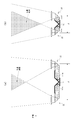
- FIG. 4A shows a left-eye image captured by the first imaging optical system 21 in the first region 111 a of the imaging device 11 and a second region 111 b of the imaging device 11 by the second imaging optical system 22.
- the imaging area of the right eye image to be imaged is shown.
- the first base line length L1 is relatively long, the common area of the left-eye image and the right-eye image is narrowed, and it is difficult to obtain parallax in a short-distance area.
- FIG. 5B shows an image of the left-eye image IFL and the right-eye image IFR when the subject as shown in FIG. 5A is imaged at the first base line length L1.
- FIG. 4B shows a left-eye image captured by the third imaging optical system 23 in the third region 111 c of the imaging device 11 and a fourth image of the imaging device 11 by the fourth imaging optical system 24.
- 4 shows an imaging region of a right-eye image captured in an area 111d.
- the second base line length L2 is relatively short, the common area of the left-eye image and the right-eye image is widened, and parallax can be obtained in a short-distance area.
- FIG. 5C shows an image of the left-eye image INL and the right-eye image INR when the subject as shown in FIG. 5A is imaged with the second base line length L2.
- FIG. 6 shows a configuration example of the vehicle control system 300.
- This vehicle control system 300 includes the camera 10 shown in FIG. 1, and the components are interconnected via a CAN bus.
- the vehicle-mounted camera 100 is disposed, for example, near the rearview mirror inside the windshield of the vehicle, and captures an image in front of the vehicle in the traveling direction.
- the image captured by the on-vehicle camera 100 is basically used for the purpose of sensing, and image processing such as image recognition is applied to the captured image, and a white line (lane) of a road, a traffic light, a road sign, an oncoming vehicle, a host vehicle It is assumed that nearby pedestrians are detected.
- the image captured by the on-vehicle camera 100 may be used for viewing purposes, and the image may be displayed in the vehicle interior.
- the vehicle camera 100 includes an imaging optical system 101, an imaging device 102, an image processing circuit 103, and a communication processing circuit 104.
- the camera 10 shown in FIG. 1 corresponds to the imaging optical system 101 and the imaging device 102.
- the image sensor 102 outputs the captured image signal to the image processing circuit 103 by, for example, serial communication.
- the image processing circuit 103 is configured by, for example, an ECU (Electronic Control Unit). In the image processing circuit 103, image processing, recognition processing, and distance measurement processing are performed based on the captured image signal.
- Image processing performed in the image processing circuit 103 includes processing such as AE (Automatic Exposure: automatic exposure control), AWB (Auto White Balance: automatic white balance adjustment), and HDR (High Dynamic Range: high dynamic range synthesis). Can be mentioned. However, these image processes can be performed on the image sensor 102 side.
- the recognition processing performed in the image processing circuit 103 includes detection of a white line (lane) of a road (Lane Detection), detection of a pedestrian (Pedestrian Detection), detection of a nearby vehicle (Vehicle Detection), and headlights for turning on an oncoming vehicle. Detection (Headlight Detection), detection of lighting of the brake light of the preceding vehicle (Automatic Emergency Breaking), signal recognition (Traffic Sign Recognition), etc. are performed.
- FIG. 7 shows an example of the configuration of the processing unit 130 that performs the object recognition process and the distance measurement process to the recognized object in the image processing circuit 103.
- the processing unit 130 includes an image division unit 131, a distortion correction unit 132, a parallax calculation unit 133, an object recognition unit 134, and a distance calculation unit 135.
- the image division unit 131 is supplied with a captured image signal obtained by the image sensor 102 (corresponding to the image sensor 11 in FIG. 1).
- the captured image signal includes the image signal Sfl of the left-eye image FL related to the first base line length L1 obtained from the first region 111a of the imaging surface 111, and includes the image signal Sfl of the second region 111b of the imaging surface 111.
- the obtained image signal Sfr of the right eye image FR related to the first base line length L1 is obtained.
- the captured image signal includes the image signal Snl of the left eye image NL relating to the second base line length L2 obtained from the third region 111c of the imaging surface 111, and the fourth region of the imaging surface 111.
- the image signal Snr of the right eye image NR related to the second base line length L2 obtained from 111d is included.
- the image dividing unit 131 extracts and outputs each of the image signal Sfl, the image signal Sfr, the image signal Snl, and the image signal Snr from the captured image signal.
- the captured image signal is an image signal of 4K resolution
- the image signal Sfl, the image signal Sfr, the image signal Snl, and the image signal Snr Are image signals of 2K (HD) resolution.
- the image signal Sfl, the image signal Sfr, the image signal Snl, and the image signal Snr output from the image division unit 131 are supplied to the distortion correction unit 132.
- the distortion correction unit 132 corrects the distortion of the optical system, and corrects the parallelism between the pair of the image signal Sfl and the image signal Sfr and the pair of the image signal Snl and the image signal Snr. This correction is a correction for converting each pair into an ideal parallelized stereo image signal obtained when two pinhole cameras are mounted in parallel.
- the image signal Sfl, the image signal Sfr, the image signal Snl, and the image signal Snr whose distortion has been corrected by the distortion correction unit 132 are supplied to the parallax calculation unit 133.
- the parallax calculation unit 133 generates a first parallax map DMf related to the first base line length L1 from the image signal Sfl and the image signal Sfr. In this case, for example, by using the image signal Sfl as a reference image and performing a matching process with the image signal Sfr for each pixel to obtain disparity information, the first disparity map DMf is generated.
- the parallax calculation unit 133 generates a second parallax map DMn related to the second base line length L2 from the image signal Snl and the image signal Snr.
- the second disparity map DMn is generated.
- the image signal Sfl and the image signal Snl whose distortion has been corrected by the distortion correction unit 132 are supplied to the object recognition unit 134.
- the object recognizing unit 134 recognizes objects (pedestrians, surrounding vehicles, etc.) based on the image signal Sfl related to the first base line length L1 using a known object recognition technology, and determines the type of each recognized object.
- the information TYf and the position information PSf in the image are output as a recognition result.
- the object recognizing unit 134 recognizes objects (pedestrians, surrounding vehicles, and the like) based on the image signal Snl relating to the second base line length L2 using a well-known object recognition technology, and recognizes each recognized object.
- Information TYn indicating the type and position information PSn in the image are output as a recognition result.
- the distance calculation unit 135 includes a first parallax map DMf related to the first base line length L1 generated by the parallax calculation unit 133 and an image signal Sfl related to the first base line length L1 obtained by the object recognition unit 134. Position information PSf in the image of each object recognized based on the information is supplied. The distance calculation unit 135 calculates the distance to each object and outputs distance information DSf. In this case, for each recognized object, the distance calculation unit 135 acquires the disparity corresponding to the object from the first disparity map DMf with reference to the position information PSf in the image of the object, and uses the disparity. Then, the distance to the object is calculated from the principle of triangulation as is conventionally known.
- the distance calculation unit 135 includes a second parallax map DMn related to the second base line length L2 generated by the parallax calculation unit 133 and an image signal related to the second base line length L2 obtained by the object recognition unit 134. Position information PSn in the image of each object recognized based on Snl is supplied. The distance calculation unit 135 calculates the distance to each object and outputs distance information DSn. In this case, the distance calculation unit 135 acquires, for each recognized object, the disparity corresponding to the object from the second disparity map DMn with reference to the position information PSn in the image of the object, and uses the disparity. Then, the distance to the object is calculated from the principle of triangulation as is well known in the art.
- the processing unit 130 recognizes an object (a pedestrian, a nearby vehicle, or the like) from the image signal Sfl related to the first base line length L1, and the information TYf indicating the type of each recognized object and the position in the image. Information PSf and distance information DSf indicating the distance to each recognized object are obtained.
- the processing unit 130 also recognizes objects (pedestrians, nearby vehicles, and the like) from the image signal Snl relating to the second base line length L2, and information TYn indicating the type of each recognized object and position information in the image. PSn and distance information DSn indicating the distance to each recognized object are obtained.
- the communication processing circuit 104 is constituted by, for example, an MCU (Micro Control Unit).
- the communication processing circuit 104 is an interface with the CAN communication in the control system 300, and performs format conversion between a signal format in the CAN communication and a signal format inside the vehicle-mounted camera 100.
- the above detection and recognition results by the image processing circuit 103 are transmitted to the vehicle control system 300 via the communication processing circuit 104.
- the communication processing unit (Communication Unit) 301 on the vehicle control system 300 performs transmission and reception of data in inter-vehicle communication, inter-vehicle communication, road-to-vehicle communication, and communication with the in-vehicle camera 100.
- the communication processing unit 301 also performs exchange with a server (not shown). It is assumed that the communication processing unit 301 can apply various types of wireless communication.
- the automatic driving control unit (Self Driving ECU) 302 is an ECU including a CPU (Central Processing Unit), an ISP (Image Signal Processor), a GPU (Graphic Processing Unit), and the like, and controls the automatic driving of the vehicle.
- the result of image recognition of the image captured by the on-board camera 100 by the GPU can be sent to the server via the communication processing unit 301, and the learning result can be received by executing deep learning by a server such as a deep neural net. .
- the driving assistance control unit (ADAS @ ECU) 303 can transmit and receive signals to and from each component of the vehicle via CAN communication.
- the driving support control unit 303 generates a control signal for controlling each component of the vehicle in accordance with the driving operation of the driver, the recognition result of the captured image by the vehicle-mounted camera 100, and the like, and sends the control signal via CAN communication.
- the steering 304, the head lamp 305, the brake 306, the engine 307, and the motor 308 are components of the vehicle that are controlled by the automatic driving control unit 302 and the driving support control unit 303. However, it should be understood that there are other components of the vehicle that can be controlled, other than those shown in FIG.
- the driving support control unit 303 when the driving support control unit 303 detects that the own vehicle is about to deviate from the white line based on the image recognition of the image captured by the on-board camera 100, it drives an EPS (Electronic Power Steering) motor for the steering 304. To send a control signal.
- the driving support control unit 303 detects the presence or absence of the headlight of the oncoming vehicle by recognizing the image captured by the on-board camera 100, and switches between the high beam and the low beam of the headlamp 305. Alternatively, a high beam is emitted so as to avoid oncoming vehicles.
- the image processing circuit 103 in the in-vehicle camera 100 may output only recognized sensing information, that is, a detection result by image recognition, instead of outputting the image information itself as the recognition processing. Some sensing information is illustrated below.
- FCW Forward Collision Warning
- AEB Automatic Emergency Breaking
- LDW Vehicle Detection for FCW / AEB -Lane Departure Warning
- TJP Traffic Jam Pilot
- controlling the vehicle speed according to the presence or absence of a preceding vehicle controlling the vehicle speed by recognizing a road sign related to the speed limit, controlling the vehicle speed by recognizing the road sign at the entrance or exit of the highway, Automatically decelerates when the vehicle approaches a curve.
- LKA Lik Keeping Aid
- VOACC Adaptive Cruise Control
- VTSR Traffic Sign Recognition
- IHC -Intelligent Head Ramp Control
- the present technology can be applied to cameras mounted on various mobile devices such as ships, aircrafts, and mobile robots in addition to cars.
- the present technology may have the following configurations.
- each of the first to fourth imaging optical systems includes a rhomboid prism.
- the rhomboid prisms included in the first to fourth imaging optical systems are respectively arranged such that an emission surface comes into contact with the first to fourth regions of the imaging surface of the imaging device.
- the camera according to (2) The camera according to (2).
- a light-blocking member is provided in at least an outer surface area of each of the rhomboid prisms included in the first to fourth imaging optical systems corresponding to the reflection surface on the emission surface side.
- the first to fourth regions on the imaging surface of the imaging device are regions obtained by dividing the imaging surface into a cross-shaped cross. Any of the above (1) to (4) Camera described.
- Imaging surface 111a first area 111b: second area 111c: third area 111d: fourth area 211, 21, 21, 231, 241: imaging Lenses 212, 222, 232, 242... Lomboid prisms 212a, 222a, 232a, 242a.
- 242c, 242d Reflecting surface 213, 223, 233, 243: Light shielding member 100: In-vehicle camera 101: Imaging optical system 102: Imaging element 1 3 image processing circuit 104 communication processing circuit 131 image dividing unit 132 distortion correcting unit 133 parallax calculating unit 134 object recognizing unit 135 distance calculating unit 300 ... Vehicle control system 301 ... Communication processing unit 302 ... Automatic driving control unit 303 ... Driving support control unit 304 ... Steering 305 ... Head lamp 306 ... Brake 307 ... Engine 308 ⁇ ⁇ ⁇ Motor
Landscapes
- Engineering & Computer Science (AREA)
- Physics & Mathematics (AREA)
- Multimedia (AREA)
- Signal Processing (AREA)
- Electromagnetism (AREA)
- General Physics & Mathematics (AREA)
- Radar, Positioning & Navigation (AREA)
- Remote Sensing (AREA)
- Measurement Of Optical Distance (AREA)
Abstract
La présente invention permet d'équilibrer la distance de dérivation à haute résolution et de dériver une parallaxe dans une région de plage proche. Une caméra comprend un élément d'imagerie et des premier à quatrième systèmes optiques d'imagerie. Le premier système optique d'imagerie forme une image de l'œil gauche selon une première longueur de ligne de base dans une première région de la surface d'imagerie de l'élément d'imagerie. Le second système optique d'imagerie forme une image de l'œil droit selon la première longueur de ligne de base dans une seconde région de la surface d'imagerie de l'élément d'imagerie. Le troisième système optique d'imagerie forme une image de l'œil gauche selon une seconde longueur de ligne de base dans une troisième région de la surface d'imagerie de l'élément d'imagerie. Le quatrième système optique d'imagerie forme une image de l'œil droit selon la seconde longueur de ligne de base dans une quatrième région de la surface d'imagerie de l'élément d'imagerie. La seconde longueur de ligne de base est inférieure à la première longueur de ligne de base.
Applications Claiming Priority (4)
| Application Number | Priority Date | Filing Date | Title |
|---|---|---|---|
| JP2018-128156 | 2018-07-05 | ||
| JP2018128156 | 2018-07-05 | ||
| JP2018158488A JP2020013096A (ja) | 2018-07-05 | 2018-08-27 | カメラ |
| JP2018-158488 | 2018-08-27 |
Publications (1)
| Publication Number | Publication Date |
|---|---|
| WO2020009172A1 true WO2020009172A1 (fr) | 2020-01-09 |
Family
ID=69060853
Family Applications (1)
| Application Number | Title | Priority Date | Filing Date |
|---|---|---|---|
| PCT/JP2019/026541 Ceased WO2020009172A1 (fr) | 2018-07-05 | 2019-07-03 | Caméra |
Country Status (1)
| Country | Link |
|---|---|
| WO (1) | WO2020009172A1 (fr) |
Cited By (1)
| Publication number | Priority date | Publication date | Assignee | Title |
|---|---|---|---|---|
| CN112887534A (zh) * | 2021-01-14 | 2021-06-01 | 维沃移动通信有限公司 | 电子设备及其控制方法和控制装置 |
Citations (3)
| Publication number | Priority date | Publication date | Assignee | Title |
|---|---|---|---|---|
| JP2001222083A (ja) * | 2000-02-07 | 2001-08-17 | Canon Inc | 撮像装置、撮像装置の制御方法、及び制御方法が記載されたプログラムをコンピュータに供給する媒体 |
| JP2010243463A (ja) * | 2009-04-10 | 2010-10-28 | Ricoh Co Ltd | ステレオカメラ装置及び車外監視装置 |
| JP2012220848A (ja) * | 2011-04-12 | 2012-11-12 | Nikon Corp | 撮像装置及びレンズ装置 |
-
2019
- 2019-07-03 WO PCT/JP2019/026541 patent/WO2020009172A1/fr not_active Ceased
Patent Citations (3)
| Publication number | Priority date | Publication date | Assignee | Title |
|---|---|---|---|---|
| JP2001222083A (ja) * | 2000-02-07 | 2001-08-17 | Canon Inc | 撮像装置、撮像装置の制御方法、及び制御方法が記載されたプログラムをコンピュータに供給する媒体 |
| JP2010243463A (ja) * | 2009-04-10 | 2010-10-28 | Ricoh Co Ltd | ステレオカメラ装置及び車外監視装置 |
| JP2012220848A (ja) * | 2011-04-12 | 2012-11-12 | Nikon Corp | 撮像装置及びレンズ装置 |
Cited By (2)
| Publication number | Priority date | Publication date | Assignee | Title |
|---|---|---|---|---|
| CN112887534A (zh) * | 2021-01-14 | 2021-06-01 | 维沃移动通信有限公司 | 电子设备及其控制方法和控制装置 |
| US12055978B2 (en) | 2021-01-14 | 2024-08-06 | Vivo Mobile Communication Co., Ltd. | Electronic device, control method thereof and control apparatus thereof |
Similar Documents
| Publication | Publication Date | Title |
|---|---|---|
| US11539868B2 (en) | Imaging system and vehicle window used for the same | |
| JP5680573B2 (ja) | 車両の走行環境認識装置 | |
| US10746874B2 (en) | Ranging module, ranging system, and method of controlling ranging module | |
| US10848660B2 (en) | Imaging apparatus, imaging module, and control method of imaging apparatus | |
| US10331963B2 (en) | Camera apparatus and in-vehicle system capturing images for vehicle tasks | |
| CN110603458B (zh) | 光学传感器和电子设备 | |
| JP2020136958A (ja) | イベント信号検出センサ及び制御方法 | |
| US10750085B2 (en) | Camera device for capturing a surrounding area of a driver's own vehicle and method for providing a driver assistance function | |
| US10882464B2 (en) | Vehicle-mounted camera, vehicle-mounted camera apparatus, and method of supporting vehicle-mounted camera | |
| JPWO2017145945A1 (ja) | ステレオカメラ装置、車両および視差算出方法 | |
| CN110073652B (zh) | 成像装置以及控制成像装置的方法 | |
| JP6699344B2 (ja) | 逆走車検出装置、逆走車検出方法 | |
| EP3667413A1 (fr) | Dispositif de traitement d'image stéréo | |
| JP7708572B2 (ja) | 移動体の制御装置、制御方法及びプログラム | |
| JP2017129543A (ja) | ステレオカメラ装置及び車両 | |
| CN115179863A (zh) | 移动体的控制装置及控制方法、存储介质以及车辆 | |
| CN112514361B (zh) | 车载相机和使用车载相机的驱动控制系统 | |
| EP2674893A2 (fr) | Système de reconnaissance de zone de déplacement, procédé de reconnaissance de zone de déplacement, programme de reconnaissance de zone circulable exécuté sur le système de reconnaissance de zone de déplacement et support d'enregistrement stockant un programme de reconnaissance de zone de déplacement possible | |
| TW201838405A (zh) | 攝像裝置、相機模組、攝像系統、及攝像裝置之控制方法 | |
| JP2013161187A (ja) | 物体認識装置 | |
| WO2020009172A1 (fr) | Caméra | |
| JP2013250694A (ja) | 画像処理装置 | |
| JP4900377B2 (ja) | 画像処理装置 | |
| JP2020013096A (ja) | カメラ | |
| CN113661700B (zh) | 成像装置与成像方法 |
Legal Events
| Date | Code | Title | Description |
|---|---|---|---|
| 121 | Ep: the epo has been informed by wipo that ep was designated in this application |
Ref document number: 19830555 Country of ref document: EP Kind code of ref document: A1 |
|
| NENP | Non-entry into the national phase |
Ref country code: DE |
|
| 122 | Ep: pct application non-entry in european phase |
Ref document number: 19830555 Country of ref document: EP Kind code of ref document: A1 |