WO2020009223A1 - Dispositif de commande de traction pour véhicule - Google Patents
Dispositif de commande de traction pour véhicule Download PDFInfo
- Publication number
- WO2020009223A1 WO2020009223A1 PCT/JP2019/026813 JP2019026813W WO2020009223A1 WO 2020009223 A1 WO2020009223 A1 WO 2020009223A1 JP 2019026813 W JP2019026813 W JP 2019026813W WO 2020009223 A1 WO2020009223 A1 WO 2020009223A1
- Authority
- WO
- WIPO (PCT)
- Prior art keywords
- amount
- output
- vehicle
- acceleration
- longitudinal acceleration
- Prior art date
- Legal status (The legal status is an assumption and is not a legal conclusion. Google has not performed a legal analysis and makes no representation as to the accuracy of the status listed.)
- Ceased
Links
Images




Classifications
-
- F—MECHANICAL ENGINEERING; LIGHTING; HEATING; WEAPONS; BLASTING
- F02—COMBUSTION ENGINES; HOT-GAS OR COMBUSTION-PRODUCT ENGINE PLANTS
- F02D—CONTROLLING COMBUSTION ENGINES
- F02D29/00—Controlling engines, such controlling being peculiar to the devices driven thereby, the devices being other than parts or accessories essential to engine operation, e.g. controlling of engines by signals external thereto
- F02D29/02—Controlling engines, such controlling being peculiar to the devices driven thereby, the devices being other than parts or accessories essential to engine operation, e.g. controlling of engines by signals external thereto peculiar to engines driving vehicles; peculiar to engines driving variable pitch propellers
Definitions
- the present invention relates to a traction control device for a vehicle.
- Patent Literature 1 discloses that a change speed of a road surface ⁇ is detected for the purpose of appropriately and promptly suppressing a slip of a drive wheel due to a decrease in a road surface ⁇ , and when the change speed is smaller than a predetermined value, that is, the road surface ⁇
- the correction coefficient for correcting the gain multiplied by the drive wheel slip amount is increased, the required torque is reduced, and the engine torque is reduced to suppress the drive wheel slip.
- XG is the longitudinal acceleration
- YG is the lateral acceleration
- K1 is a constant”.
- Patent Document 2 provides a road friction coefficient equivalent value estimating means for estimating a road surface friction coefficient equivalent value in order to achieve both hunting prevention on a low ⁇ road and vibration prevention on a high ⁇ road during motor traction control, At the time of motor traction control, the road surface friction coefficient equivalent value reduces the phase delay of the motor torque command value with respect to the calculated motor torque limit value on the low friction coefficient side, and the road surface friction coefficient equivalent value is calculated on the high friction coefficient side. It is described that the phase delay of the motor torque command value with respect to the motor torque limit value is increased.
- Japanese Patent Application Laid-Open No. H11-163,086 discloses a method for detecting a change in the road surface friction coefficient. If the detected value indicates a positive angular acceleration equal to or greater than the second set value, it is determined that the road surface friction coefficient suddenly changes from a high ⁇ road to a low ⁇ road. Have been.
- An object of the present invention is to provide a traction control device for a vehicle, in which a case in which a friction coefficient of a road surface is changed from a high state to a low state is suitably determined, stable traction control is performed, and a feeling of acceleration can be improved. It is to provide.
- the vehicle traction control device (TS) suppresses excessive acceleration slip (Sw) of the drive wheels (WHf, WHr) to which the output (Qa) of the vehicle power source (EN) is transmitted.
- the output (Qa) is limited.
- the traction control device (TS) for the vehicle includes an “acceleration calculation unit (GA) that calculates the longitudinal acceleration (Ga) of the vehicle at a predetermined calculation cycle” and “the acceleration calculation unit (GA) that calculates the preceding longitudinal acceleration (Ga) at the calculation cycle.
- the previous value (Ga [n-1]), the present longitudinal acceleration (Ga) in the calculation cycle is set as the current value (Ga [n]), and the current value from the previous value (Ga [n-1]) is calculated.
- a reduction amount (Gg [n]) of the value (Ga [n]) is calculated, and the reduction amount (Gg [n]) is integrated for each calculation cycle to obtain an integrated amount (Sg [n]).
- Calculation section (SG) "and" adjustment section (CQ) for reducing the output (Qt, Qa) when the integrated amount (Sg [n]) exceeds a predetermined amount (sx) ". It consists of.
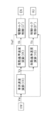
- FIG. 1 is an overall configuration diagram of a vehicle equipped with a vehicle traction control device TS according to the present invention. It is a functional block diagram for explaining an outline of traction control device TS. It is a functional block diagram for explaining drive torque control of traction control device TS.
- FIG. 9 is a time-series diagram for describing processing in a decrease amount calculation block SG.
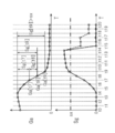
- FIG. 9 is a time-series diagram for explaining a process of reducing an integrated amount Sg. It is a time series diagram for demonstrating an effect
- the drive device YD is connected to the front wheels WHf via the drive shaft DS. That is, the vehicle is a front-wheel drive vehicle in which the front wheels WHf are used as drive wheels.
- the vehicle includes a braking operation member BP, a braking operation amount sensor BA, an acceleration operation member AP, an acceleration operation amount sensor AA, a shift operation member HP, a shift position sensor HA, a steering operation member SW, a steering angle sensor SA, and a wheel speed sensor VW.
- a yaw rate sensor YR a longitudinal acceleration sensor GX, a lateral acceleration sensor GY, a braking device YB, and a driving device YD.
- the braking operation member (for example, a brake pedal) BP is a member operated by the driver to decelerate the vehicle. By operating the braking operation member BP, the braking torque Bq for the wheel WH is adjusted, and a braking force is generated on the wheel WH.
- a brake operation amount sensor BA is provided to detect the operation amount Ba of the brake operation member (brake pedal) BP by the driver.
- a master cylinder pressure sensor PM for detecting a hydraulic pressure (master cylinder pressure) Pm in the master cylinder CM
- an operation displacement sensor for detecting an operation displacement Sp of the braking operation member BP.
- SP not shown
- an operating force sensor FP not shown
- the acceleration operation member (for example, accelerator pedal) AP is a member operated by the driver to accelerate the vehicle and run at a constant speed. By operating the acceleration operation member AP, the driving torque Tq for the wheel WH is adjusted, and a driving force is generated on the wheel WH.
- An acceleration operation amount sensor AA is provided to detect an operation amount Aa of the acceleration operation member (accelerator pedal) AP by the driver.
- an acceleration operation displacement sensor that detects an operation displacement of the acceleration operation member AP is employed as the acceleration operation amount sensor AA.
- the vehicle is provided with a shift operation member (for example, a shift lever) HP for performing a shift operation. Further, a shift position sensor HA for detecting a shift position Ha of the shift operation member HP is provided.
- a shift operation member for example, a shift lever
- a shift position sensor HA for detecting a shift position Ha of the shift operation member HP is provided.
- a steering operation member (for example, a steering wheel) SW is a member operated by a driver to turn the vehicle.
- a steering angle Sa is given to a steered wheel (for example, the front wheel WHf), a lateral force is generated on the wheel WH, and the vehicle turns.
- a steering angle sensor SA is provided to detect a rotation angle (steering angle) Sa of the steering operation member SW.
- the wheel WH is provided with a wheel speed sensor VW for detecting a wheel speed Vw which is a rotation speed of the wheel WH.
- the vehicle body includes a yaw rate sensor YR for detecting the yaw rate Yr of the vehicle, a longitudinal acceleration sensor GX for detecting an acceleration (longitudinal acceleration) Gx in the longitudinal direction of the vehicle, and an acceleration (lateral acceleration) Gy in the lateral direction of the vehicle.
- a lateral acceleration sensor GY for detecting is provided.
- the braking device YB includes a master cylinder CM, a brake caliper CP, a wheel cylinder CW, a rotating member KT, a friction material MS, a fluid unit HU, and a braking controller ECB.
- the master cylinder CM, the fluid unit HU, and the wheel cylinder CW are connected via a braking fluid path HW.
- Each wheel WH of the vehicle includes a brake caliper CP, a wheel cylinder CW, a rotating member KT, and a friction material MS.
- a rotating member (brake disc) KT is fixed to the wheel WH, and a brake caliper CP is arranged.
- the brake caliper CP is provided with a wheel cylinder CW.
- the fluid unit HU is operated when anti-skid control, traction control, vehicle stabilization control, etc. are executed.
- the brake hydraulic pressure Pw is adjusted independently of the operation of the brake operation member BP and individually for each wheel.
- the fluid unit HU includes an electric pump, a plurality of solenoid valves, and a low-pressure reservoir.
- the fluid unit HU (in particular, the electric motor of the electric pump and the solenoid valve) is controlled by the braking controller ECB.
- the braking operation amount Ba (Pm, Sp, Fp), the wheel speed Vw, the yaw rate Yr, the steering angle Sa, the longitudinal acceleration Gx, the lateral acceleration Gy, and the like are input to the controller ECB.
- anti-skid control is performed so as to suppress excessive deceleration slip (for example, wheel lock) of the wheel WH.
- traction control is executed so as to suppress excessive acceleration slip (for example, wheel spin) of the wheel WH.
- a driving force is generated by the driving device YD on driving wheels (wheels connected to the driving device YD) among the wheels WH.
- the drive device YD includes a power source EN (also referred to as a “drive source”), a transmission TM, and a drive controller ECD.
- the power source EN (for example, an internal combustion engine) is controlled by the drive controller ECD according to the acceleration operation amount Aa.
- the transmission TM (for example, an automatic transmission) is controlled by the drive controller ECD according to the shift position Ha.
- a torque converter TC is included between power source EN and transmission TM, and output Qa of power source EN is transmitted to transmission TM via torque converter TC.
- the power source EN is provided with a throttle sensor TH for detecting the throttle opening Th, an injection amount sensor FI for detecting the fuel injection amount Fi, and a rotation speed sensor NE for detecting the driving rotation speed Ne.
- the drive controller ECD calculates the acceleration operation amount Aa (actual value), the throttle opening Th (actual value), the fuel injection amount Fi (actual value), and the driving speed Ne (actual value) of the power source EN.
- Output Qa of power source EN is controlled.
- An electric motor for driving may be adopted as the power source EN. In this case, the amount of current (for example, current value) Im to the power source EN and the rotational speed Nm are detected. Then, the output Qa of the driving motor is controlled based on the acceleration operation amount Aa (actual value), the energization amount Im (actual value), and the motor speed Nm (actual value).
- the transmission TM is provided with a gear position sensor GP for detecting a gear ratio (gear position) Gp (actual value).
- the gear ratio Gp of the automatic transmission TM is controlled by the drive controller ECD based on signals (Aa, Th, Fi, Ne, Im, Nm, etc.) related to the power source EN.
- the drive controller ECD calculates and outputs the required throttle opening Ths, the fuel injection amount Fis, and the required gear ratio Gps based on the acceleration operation amount Aa.
- the required throttle opening Ths, the fuel injection amount Fis, and the required gear ratio Gps are target values of the throttle opening Th, the fuel injection amount Fi, and the gear ratio Gp.
- the actual throttle opening Th, the actual fuel injection amount Fi, and the actual gear ratio Gp are controlled so as to match the required throttle opening Ths, the required fuel injection amount Fis, and the required gear ratio Gps.
- the power source EN is an electric motor
- the required energization amount (target value) Ims is calculated based on the acceleration operation amount Aa, and control is performed so that the actual energization amount Im matches the target value Ims. You.
- the drive controller ECD and the brake controller ECB share information (computed values, sensor values, etc.) via the communication bus BS. For example, traction control, vehicle stabilization control, and the like are executed by the braking controller ECB.
- the output of the power source EN is reduced by the drive controller ECD in response to the instruction signal (target output Qt) from the brake controller ECB.
- a controller that shares information via the communication bus BS is called an “ECU (electronic control unit)”. That is, the controller ECU includes at least the drive controller ECD and the brake controller ECB.
- the outline of the traction control device TS will be described with reference to the functional block diagram of FIG.
- the traction control device TS includes “processing for controlling the power source (drive source) EN to control the drive torque Tq of the drive wheel WHf (front wheel)” and “processing for controlling the fluid unit HU to drive the drive wheel WHf.
- the traction control device TS includes a vehicle speed calculation block VX, a driving reference speed calculation block VK, a driving torque control block QT, a braking reference speed calculation block VS, and a braking torque control block BT.
- the vehicle speed Vx is calculated in the vehicle speed calculation block VX based on the wheel speed Vw.
- the vehicle speed Vx is calculated based on the wheel speed Vwr of the driven wheel WHr.
- the driven wheel WHr is a wheel to which power from the driving device YD is not transmitted, and corresponds to a rear wheel WHr in a front-wheel-drive vehicle.
- the drive reference speed calculation block VK calculates the drive reference speed Vk based on the vehicle speed Vx.
- the drive reference speed Vk is a wheel speed serving as a reference when the output Qa of the power source EN is controlled (during drive torque control).
- the predetermined speed vk is a predetermined value (constant) set in advance.
- the target output Qt is calculated based on the drive reference speed Vk and the drive wheel speed Vwf.
- the target output Qt is a target value (limit value) for limiting the actual output Qa of the power source EN. Therefore, when the actual output Qa is equal to or less than the target output Qt, the output Qa of the power source EN is not limited.
- the throttle opening Th and the fuel injection amount Fi are reduced so that the output Qa becomes equal to or less than the target output Qt. Output Qa is reduced. As a result, the drive torque Tq of WHf is reduced, and excessive acceleration slip Sw is suppressed. Details of the drive torque control block QT will be described later.
- the reference braking speed Vs is calculated based on the vehicle speed Vx.
- the braking reference speed Vs is a wheel speed serving as a reference when the braking fluid pressure Pw is controlled (during braking torque control).
- the predetermined speed vs is a predetermined value (constant) set in advance, and has a relationship of “vs> vk”.
- the fluid unit HU is controlled based on the braking reference speed Vs and the driving wheel speed Vwf. Specifically, the brake fluid pressure Pw is adjusted such that the drive wheel speed Vwf approaches and coincides with the braking reference speed Vs.
- the braking reference speed Vs is higher than the driving reference speed Vk. Therefore, in the traction control, first, the driving torque control is executed.
- the driving torque control is executed.
- the drive wheel speed Vwf does not increase or does not sufficiently decrease despite the output Qa being reduced by the drive torque control
- the acceleration slip Sw of the drive wheel WHf is rapidly reduced by the braking torque control block BT.
- the braking hydraulic pressure Pwf is increased (that is, the braking torque Bq of the drive wheel WHf is increased).
- the details of the drive torque control of the traction control device TS will be described with reference to the functional block diagram of FIG.
- the driving torque control includes a vehicle speed calculation block VX, a drive reference speed calculation block VK, a drive wheel average speed calculation block VH, a proportional / integral control block QS, a longitudinal acceleration calculation block GA, a decrease amount calculation block SG, and an adjustment processing block. It is composed of CQ.
- the vehicle speed Vx is calculated in the vehicle speed calculation block VX based on the wheel speed Vw (particularly, the wheel speed Vwr of the driven wheel WHr).
- a predetermined speed vk (for example, a constant) is added to the vehicle body speed Vx to determine a drive reference speed Vk (also simply referred to as “reference speed Vk”).
- the driving wheel average speed Vh (also simply referred to as “average speed Vh”) is calculated based on the wheel speed Vwf of the driving wheel WHf.
- the drive wheel WHf is a wheel to which power from the drive device YD is transmitted, and corresponds to the front wheel WHf in a front-wheel drive vehicle.
- the average speed Vh is an average value of the two drive wheel speeds Vwf.
- the predetermined values sz and qs are preset constants.
- the longitudinal acceleration Ga is calculated based on the vehicle speed Vx.
- the longitudinal acceleration Ga is the actual longitudinal acceleration (actual acceleration) of the vehicle (body).
- the vehicle speed Vx is time-differentiated at a predetermined calculation cycle (for example, every several milliseconds), and the longitudinal acceleration Ga is calculated.
- the longitudinal acceleration Gx detected by the longitudinal acceleration sensor GX may be employed as the longitudinal acceleration Ga.
- both the longitudinal acceleration Gx (detected value) and the longitudinal acceleration Ga (calculated value) may be used as the longitudinal acceleration Ga so as to improve the robustness.
- the integrated amount Sg is calculated based on the longitudinal acceleration Ga.
- the integrated amount Sg is a decrease amount from the peak value of the longitudinal acceleration Ga.
- the current longitudinal acceleration Ga [n] (from the previous longitudinal acceleration Ga [n ⁇ 1] (corresponding to “previous value”) ( The amount of reduction Gg [n] corresponding to “current value” is calculated.
- “n” at the end of the symbol indicates the operation cycle
- “n” indicates the current (current) operation cycle
- “n-1" indicates the immediately preceding operation cycle (previous), respectively.
- the reduction amount Gg [n] is sequentially accumulated for each calculation cycle.
- the predetermined ratio rs is a preset constant. For example, the predetermined ratio rs is set to “0%”. In this case, when the longitudinal acceleration Ga increases, the integrated value Sg is reset to “0”.
- the decrease amount calculation block SG includes a timer (time counter). The continuation of time is calculated by this timer. For the first time after the traction control is started, the continuation time is counted from the time when the longitudinal acceleration Ga decreases (the corresponding calculation cycle). The integrated value Sg is reset to “0” when a predetermined time tx has elapsed from the time when the state where the integrated value Sg is larger than the predetermined amount sx is satisfied for the first time.
- the predetermined amount sx and the predetermined time tx are preset constants.
- the required output Qs (also referred to as “required torque”) is adjusted based on the integrated amount Sg, and the target output Qt (also referred to as “target torque”) is calculated. Is done.
- the target output Qt (target torque) is a final target value of the limited torque in the drive torque control.
- Qa ⁇ Qt no limitation is performed and the actual output Qa is not reduced.
- Qa> Qt the power source EN is controlled so that the actual output Qa decreases to the target output Qt (throttle opening Th, fuel injection amount Fi, and motor power amount Im are reduced).
- the adjustment output Qg is for reducing and adjusting the required output Qs to determine the final target output Qt.
- the predetermined amount sx is a threshold value for determining whether or not the required output Qs is adjusted to be reduced or not (that is, whether to calculate the adjusted output Qg or not), and is a predetermined constant set in advance. It is.
- the adjustment output Qg is set as the predetermined torque qg.
- the predetermined torque qg is a preset constant.
- the adjustment output Qg can be determined based on at least one of the slip state sw and the duration time tg.
- the slip state sw is a value of the acceleration slip Sw at the time when “Sg> sx” is satisfied (a corresponding calculation cycle). As shown in the calculation map Zs of the blowing section, the calculation is performed such that the adjustment output Qg increases as the slip state sw increases. The fact that the slip state sw is large is based on the fact that the target output Qt should be made smaller.
- the duration tg is the time from the time when the increase of the integrated amount Sg is started to the time when “Sg> sx” is satisfied. As shown in the calculation map Zt, the adjustment output Qg is calculated so as to be smaller as the duration tg is longer.
- the long duration time tg is based on the fact that the longitudinal acceleration does not decrease so much and the acceleration slip Sw does not increase rapidly.
- the actual longitudinal acceleration Ga is calculated.
- the amount of decrease Gg of the longitudinal acceleration Ga (the amount Gg [n] reduced from the previous value Ga [n-1] in the current value Ga [n]) is calculated in each calculation cycle.
- the total of the reduction amounts Gg from the time when the longitudinal acceleration Ga exhibits the peak value and the decrease in the longitudinal acceleration Ga is started ie, the calculation cycle in which the decrease in the longitudinal acceleration Ga is determined) is the integrated amount Sg It is.
- the adjustment output Qg adjustment torque
- the target output Qt target torque
- the predetermined amount sx is a threshold value (a preset constant) for determining whether or not the adjustment output Qg is necessary.
- the adjustment for decreasing the target output Qt is ended when the increase in the longitudinal acceleration Ga is started.
- the decrease adjustment can be ended when the integrated value Sg becomes equal to or less than the predetermined amount sx.
- the decrease adjustment may be terminated when a predetermined time tx (a preset constant) has elapsed from the time when “Sg> sx” is satisfied for the first time.
- the adjustment output Qg is not immediately set to “0”, but is gradually decreased (with the time change gradient limited) toward “0”.
- the target output Qt is smoothly increased to the required output Qs so that a sudden change in the output Qa is suppressed.
- the target output Qt is greatly reduced when the longitudinal acceleration Ga continues to decrease during vehicle acceleration.
- the state where the road surface friction coefficient is high is changed.
- the case where the state has changed to a low state is appropriately determined.
- the road surface friction state is determined using not only the state quantity at the present time but also the past state quantity, the complexity of the control due to the fluctuation of the control amount of the traction control is suppressed.
- the actual output Qa is reduced to a value suitable for the road surface friction coefficient. Excessive acceleration slip Sw of the drive wheel WHf is quickly suppressed, and the convergence of the drive wheel WHf is improved. As a result, the driver's feeling of acceleration of the vehicle is improved.
- the integrated amount Sg [t9] is calculated as “Sg [t8] + Gg [t9]”.
- the target output Qt is greatly reduced (ie, sharply reduced).
- the longitudinal acceleration Ga [t15] increases from the longitudinal acceleration Ga [t14].
- rs 0%
- the integrated amount Sg [t15] is reset to “0”.
- the integrated amount Sg [t15] is determined to be “1 /” of the integrated amount Sg [t14] (see the characteristic indicated by the broken line).
- the integrated amount Sg increases.
- the integrated amount Sg decreases repeatedly.
- the longitudinal acceleration Ga increases
- the integrated amount Sg is equal to or less than the threshold value sx
- the duration of the decrease adjustment is a predetermined time tz (a preset constant)” At least one of the above is adopted.
- the “increase of the longitudinal acceleration Ga” or the “condition of“ Sg ⁇ sx ”due to the decrease of the integrated amount Sg” is satisfied, and the decrease adjustment of the target output Qt is ended.
- the adjustment output Qg is gradually reduced and the target output Qt is gradually increased so as to avoid a sudden change in the actual output Qa.
- FIG. 5 (a) shows a decreasing process when the longitudinal acceleration Ga increases.
- “Ga [u5] ⁇ Ga [u4]” so that the integrated amount Sg [u5] is calculated.
- the longitudinal acceleration Ga decreases, the integrated amount Sg increases.
- “Ga [u10] ⁇ Ga [u9]” is satisfied, and the longitudinal acceleration Ga is increased.
- FIG. 5B shows a decreasing process when the increase of the integrated amount Sg exceeds the predetermined time tx.
- the calculation of the integrated amount Sg is started and starts to increase from “0”.
- the longitudinal acceleration Ga decreases, the integrated amount Sg is sequentially increased. Since the state of “Sg ⁇ sx” is continued, the reduction of the target output Qt is not executed.
- the duration of “Sg ⁇ sx” becomes equal to or longer than tx.
- the integrated amount Sg [v17] is reset to “0”.
- the integrated amount Sg [n] is reset to “0”, and the target output Qt decreases. I can't.
- the integrated amount Sg has been increased, when it takes time to reach the predetermined amount sx, the road surface friction coefficient is not so low, and the necessity for the rapid decrease of the target output Qt is low. Unnecessary reduction of the target output Qt can be avoided by the reduction processing based on the duration of the integrated amount Sg, and the reliability of control can be improved.
- FIG. 6A shows a case where the present invention is not applied
- FIG. 6B shows a case where the present invention is applied.
- the acceleration operation amount Aa is made constant, and an instruction output Qd (constant value ta) is instructed to the power source EN by the drive controller ECD. It is assumed that the friction coefficient of the vehicle traveling path has changed from a high state to a low state.
- the command output Qd is limited by the target output Qt ( ⁇ Qd), and the output Qa of the power source EN is suppressed (reduced).
- ⁇ Qd target output
- the output Qa of the power source EN is suppressed (reduced).
- the command output Qd by the driver is limited by the target output Qt by the traction control, but since the restriction is insufficient, it takes time for the average speed Vh to converge to the drive reference speed Vk. Since the acceleration slip Sw becomes excessive and a driving force corresponding to the road surface friction coefficient cannot be obtained, the driver may feel "slack" in vehicle acceleration.
- Traction controller TS suppresses excessive acceleration slip Sw of drive wheel WHf to which output Qa of power source EN is transmitted.
- the traction control device TS includes a longitudinal acceleration calculation block GA, a decrease calculation block SG, and an adjustment processing block CQ.
- the longitudinal acceleration calculation block GA (acceleration calculation unit) calculates the longitudinal acceleration Ga at a predetermined calculation cycle. For example, in the longitudinal acceleration calculation block GA, the longitudinal acceleration Ga is calculated by differentiating the time based on the vehicle speed Vx corresponding to the wheel speed Vw. Further, based on the longitudinal acceleration Gx (detected value) detected by the longitudinal acceleration sensor GX, it is filtered to determine the longitudinal acceleration Ga.
- the decrease amount calculation block SG stores the previous longitudinal acceleration Ga [n ⁇ 1] (previous value) in the calculation cycle.
- the current longitudinal acceleration Ga [n] current value
- the amount of reduction Gg [n] of the current value Ga [n] from the previous value Ga [n-1] is calculated.
- the reduction amount Gg [n] is integrated for each calculation cycle to determine the integration amount Sg [n].
- the adjustment processing block CQ adjustment unit
- the integrated amount Sg [n] exceeds a predetermined amount sx (a predetermined threshold for determination)
- the output Qa of the power source EN is reduced.
- the adjustment output Qg determined according to the integrated amount Sg is subtracted from the required output Qs calculated based on the acceleration slip Sw, and the target output Qt is rapidly reduced.
- the drive controller ECD controls the actual output Qa to approach and match the target output Qt, so that the output Qa is sharply reduced.
- the traction control device TS Similar to the conventional control, the traction control is started at the time point x1. From time point x1, the integrated amount Sg is calculated based on the decrease amount Gg of the longitudinal acceleration Ga. In “Sg ⁇ sx”, the required output Qs is determined as the target output Qt. At the time x2 at which the longitudinal acceleration Ga continues to decrease and “Sg> sx” is satisfied, the adjustment output Qg is calculated, the adjustment output Qg is reduced from the required output Qs, and the target output Qt is reduced. At time point x2, target output Qt is sharply reduced from value tb to value tc.
- the road surface friction coefficient has changed from a high state to a low state, and the actual output Qa is reduced to a value suitable for the road surface friction coefficient. Is reduced.
- the average speed Vh (the average value of the two drive wheel speeds Vwf) quickly approaches the drive reference speed Vk. That is, the convergence of the wheel speed Vwf of the driving wheel WHf is improved, and the driving force of the driving wheel WHf can be appropriately secured according to the decrease in the road surface friction coefficient.
- the integrated amount Sg [n] is obtained by multiplying the integrated value Sg [n-1] by a predetermined ratio rs. It is reduced to a value (eg, reset to “0 (zero)”). Further, in the decrease amount calculation block SG, when the state in which the integrated amount Sg [n] is equal to or smaller than the predetermined amount sx is continued for a predetermined time tx or longer, the integrated amount Sg [n] is set to “0 (zero)”. Is reset to Thereby, the reliability of the control in reducing the target output Qt can be improved.
- the traction control device TS is applied to a front wheel drive vehicle in which the drive wheels connected to the power source EN are the front wheels WHf.
- the traction control device TS can be applied to a rear-wheel drive vehicle.
- the driving wheel is the rear wheel WHr
- the driven wheel is the front wheel WHf.
- at least one of the differential value (calculated value) of the vehicle body speed Vx and the detected longitudinal acceleration Gx (the detected value of the longitudinal acceleration sensor GX) is adopted as the longitudinal acceleration Ga.
- the traction control device TS may be applied to a four-wheel drive vehicle.
- a four-wheel drive vehicle it is preferable to use the detected longitudinal acceleration Gx as the longitudinal acceleration Ga.
- four wheels are drive wheels, it is based on the fact that all the wheels WH include the acceleration slip Sw.
Landscapes
- Engineering & Computer Science (AREA)
- Chemical & Material Sciences (AREA)
- Combustion & Propulsion (AREA)
- Mechanical Engineering (AREA)
- General Engineering & Computer Science (AREA)
- Control Of Vehicle Engines Or Engines For Specific Uses (AREA)
- Regulating Braking Force (AREA)
Abstract
L'invention concerne un dispositif de commande de traction qui limite la sortie d'une source d'énergie motrice de façon à réduire au minimum le glissement excessif d'accélération des roues motrices. Le dispositif de commande de traction est conçu pour comprendre : une unité de calcul de taux d'accélération qui calcule un taux d'accélération longitudinale dans un cycle de calcul prescrit ; une unité de calcul de quantité de réduction qui désigne le dernier taux d'accélération longitudinale dans le cycle de calcul en tant que dernière valeur Ga[n-1], désigne le taux d'accélération longitudinale actuel dans le cycle de calcul en tant que valeur actuelle Ga[n], calcule une quantité de réduction Gg[n] de la valeur actuelle Ga[n] à partir de la dernière valeur Ga[n-1], et additionne les quantités de réduction Gg[n] à chaque cycle de calcul pour obtenir une quantité cumulative Sg[n] ; et une unité de réglage qui réduit la sortie lorsque la quantité cumulative Sg[n] dépasse une quantité prescrite sx.
Applications Claiming Priority (2)
| Application Number | Priority Date | Filing Date | Title |
|---|---|---|---|
| JP2018-128710 | 2018-07-06 | ||
| JP2018128710A JP7099096B2 (ja) | 2018-07-06 | 2018-07-06 | 車両のトラクション制御装置 |
Publications (1)
| Publication Number | Publication Date |
|---|---|
| WO2020009223A1 true WO2020009223A1 (fr) | 2020-01-09 |
Family
ID=69059179
Family Applications (1)
| Application Number | Title | Priority Date | Filing Date |
|---|---|---|---|
| PCT/JP2019/026813 Ceased WO2020009223A1 (fr) | 2018-07-06 | 2019-07-05 | Dispositif de commande de traction pour véhicule |
Country Status (2)
| Country | Link |
|---|---|
| JP (1) | JP7099096B2 (fr) |
| WO (1) | WO2020009223A1 (fr) |
Families Citing this family (1)
| Publication number | Priority date | Publication date | Assignee | Title |
|---|---|---|---|---|
| JP7282245B1 (ja) * | 2022-10-14 | 2023-05-26 | 三菱重工業株式会社 | 再粘着制御装置、再粘着制御方法、およびプログラム |
Citations (2)
| Publication number | Priority date | Publication date | Assignee | Title |
|---|---|---|---|---|
| JP2005048696A (ja) * | 2003-07-30 | 2005-02-24 | Advics:Kk | トラクション制御装置 |
| JP2009234563A (ja) * | 2008-03-03 | 2009-10-15 | Nissan Motor Co Ltd | 車両のトラクション制御装置 |
Family Cites Families (4)
| Publication number | Priority date | Publication date | Assignee | Title |
|---|---|---|---|---|
| JP2005161968A (ja) | 2003-12-02 | 2005-06-23 | Advics:Kk | 車輪スリップ制御装置および車輪スリップ制御方法 |
| JP4182944B2 (ja) | 2004-11-09 | 2008-11-19 | 日産自動車株式会社 | 車両のモータトラクション制御装置 |
| JP2008261303A (ja) | 2007-04-13 | 2008-10-30 | Toyota Motor Corp | 車両のトラクションコントロール装置 |
| JP7099097B2 (ja) | 2018-07-06 | 2022-07-12 | 株式会社アドヴィックス | 車両のトラクション制御装置 |
-
2018
- 2018-07-06 JP JP2018128710A patent/JP7099096B2/ja active Active
-
2019
- 2019-07-05 WO PCT/JP2019/026813 patent/WO2020009223A1/fr not_active Ceased
Patent Citations (2)
| Publication number | Priority date | Publication date | Assignee | Title |
|---|---|---|---|---|
| JP2005048696A (ja) * | 2003-07-30 | 2005-02-24 | Advics:Kk | トラクション制御装置 |
| JP2009234563A (ja) * | 2008-03-03 | 2009-10-15 | Nissan Motor Co Ltd | 車両のトラクション制御装置 |
Also Published As
| Publication number | Publication date |
|---|---|
| JP7099096B2 (ja) | 2022-07-12 |
| JP2020007948A (ja) | 2020-01-16 |
Similar Documents
| Publication | Publication Date | Title |
|---|---|---|
| CN107709125B (zh) | 加减速控制装置 | |
| US9895978B2 (en) | Braking force control method for vehicle | |
| JP2001171504A (ja) | 路面摩擦係数推定装置 | |
| US8924116B2 (en) | Motion control apparatus for vehicle | |
| JP2009067358A (ja) | 車両自動走行制御装置 | |
| US11351969B2 (en) | Operation control device for tractor vehicle | |
| JPH0692751B2 (ja) | 加速スリツプ制御装置 | |
| US7628241B2 (en) | Turning control apparatus for vehicle | |
| JP2025030447A (ja) | 車両の制動制御装置 | |
| JPH10287262A (ja) | 車両の挙動制御装置 | |
| CN108621787A (zh) | 四轮驱动车辆的控制装置 | |
| JP2015020626A (ja) | トラクションコントロールシステム | |
| JP5226086B2 (ja) | 油圧式駆動装置を備えた車両の車輪の車輪基準回転速度の決定方法および装置 | |
| JP2007186020A (ja) | 車両の運動制御装置 | |
| JP7099096B2 (ja) | 車両のトラクション制御装置 | |
| JP4950052B2 (ja) | 電子的に制御可能なディファレンシャルロック機構のロックレベルを制御するための方法及び装置 | |
| JP2016190607A (ja) | 車両の制御装置 | |
| JP7099097B2 (ja) | 車両のトラクション制御装置 | |
| JP3105045B2 (ja) | 車両のスリップ制御装置 | |
| CN113386734B (zh) | 驱动力控制装置 | |
| JP7069626B2 (ja) | 牽引車両の運動制御装置 | |
| JP7099028B2 (ja) | 車両の走行路判定装置 | |
| JP7003555B2 (ja) | 牽引車両の運動制御装置 | |
| US11827211B2 (en) | Vehicle control system | |
| JP2021054371A (ja) | 制動制御装置 |
Legal Events
| Date | Code | Title | Description |
|---|---|---|---|
| 121 | Ep: the epo has been informed by wipo that ep was designated in this application |
Ref document number: 19831367 Country of ref document: EP Kind code of ref document: A1 |
|
| NENP | Non-entry into the national phase |
Ref country code: DE |
|
| 122 | Ep: pct application non-entry in european phase |
Ref document number: 19831367 Country of ref document: EP Kind code of ref document: A1 |