WO2020009267A1 - Rit를 사용한 귀걸이형 보청기 - Google Patents
Rit를 사용한 귀걸이형 보청기 Download PDFInfo
- Publication number
- WO2020009267A1 WO2020009267A1 PCT/KR2018/010133 KR2018010133W WO2020009267A1 WO 2020009267 A1 WO2020009267 A1 WO 2020009267A1 KR 2018010133 W KR2018010133 W KR 2018010133W WO 2020009267 A1 WO2020009267 A1 WO 2020009267A1
- Authority
- WO
- WIPO (PCT)
- Prior art keywords
- receiver
- hearing aid
- ear
- sound signal
- receiver tube
- Prior art date
- Legal status (The legal status is an assumption and is not a legal conclusion. Google has not performed a legal analysis and makes no representation as to the accuracy of the status listed.)
- Ceased
Links
Images


Classifications
-
- H—ELECTRICITY
- H04—ELECTRIC COMMUNICATION TECHNIQUE
- H04R—LOUDSPEAKERS, MICROPHONES, GRAMOPHONE PICK-UPS OR LIKE ACOUSTIC ELECTROMECHANICAL TRANSDUCERS; ELECTRIC HEARING AIDS; PUBLIC ADDRESS SYSTEMS
- H04R25/00—Electric hearing aids
- H04R25/45—Prevention of acoustic reaction, i.e. acoustic oscillatory feedback
-
- H—ELECTRICITY
- H04—ELECTRIC COMMUNICATION TECHNIQUE
- H04R—LOUDSPEAKERS, MICROPHONES, GRAMOPHONE PICK-UPS OR LIKE ACOUSTIC ELECTROMECHANICAL TRANSDUCERS; ELECTRIC HEARING AIDS; PUBLIC ADDRESS SYSTEMS
- H04R25/00—Electric hearing aids
- H04R25/02—Electric hearing aids adapted to be supported entirely by ear
-
- H—ELECTRICITY
- H04—ELECTRIC COMMUNICATION TECHNIQUE
- H04R—LOUDSPEAKERS, MICROPHONES, GRAMOPHONE PICK-UPS OR LIKE ACOUSTIC ELECTROMECHANICAL TRANSDUCERS; ELECTRIC HEARING AIDS; PUBLIC ADDRESS SYSTEMS
- H04R25/00—Electric hearing aids
- H04R25/50—Customised settings for obtaining desired overall acoustical characteristics
- H04R25/505—Customised settings for obtaining desired overall acoustical characteristics using digital signal processing
-
- H—ELECTRICITY
- H04—ELECTRIC COMMUNICATION TECHNIQUE
- H04R—LOUDSPEAKERS, MICROPHONES, GRAMOPHONE PICK-UPS OR LIKE ACOUSTIC ELECTROMECHANICAL TRANSDUCERS; ELECTRIC HEARING AIDS; PUBLIC ADDRESS SYSTEMS
- H04R25/00—Electric hearing aids
- H04R25/60—Mounting or interconnection of hearing aid parts, e.g. inside tips, housings or to ossicles
- H04R25/602—Mounting or interconnection of hearing aid parts, e.g. inside tips, housings or to ossicles of batteries
-
- H—ELECTRICITY
- H04—ELECTRIC COMMUNICATION TECHNIQUE
- H04R—LOUDSPEAKERS, MICROPHONES, GRAMOPHONE PICK-UPS OR LIKE ACOUSTIC ELECTROMECHANICAL TRANSDUCERS; ELECTRIC HEARING AIDS; PUBLIC ADDRESS SYSTEMS
- H04R2430/00—Signal processing covered by H04R, not provided for in its groups
- H04R2430/01—Aspects of volume control, not necessarily automatic, in sound systems
-
- H—ELECTRICITY
- H04—ELECTRIC COMMUNICATION TECHNIQUE
- H04R—LOUDSPEAKERS, MICROPHONES, GRAMOPHONE PICK-UPS OR LIKE ACOUSTIC ELECTROMECHANICAL TRANSDUCERS; ELECTRIC HEARING AIDS; PUBLIC ADDRESS SYSTEMS
- H04R25/00—Electric hearing aids
- H04R25/65—Housing parts, e.g. shells, tips or moulds, or their manufacture
- H04R25/652—Ear tips; Ear moulds
- H04R25/654—Ear wax retarders
Definitions
- the present invention relates to an earring-type hearing aid, and more particularly, to an earring-type hearing aid using RIT (RECEIVER IN THE TUBE) capable of custom-fitting according to a user and solving an acoustic feedback phenomenon.
- RIT RECEIVER IN THE TUBE
- the human ear is divided into three parts: the outer ear, middle ear, and inner ear.
- Vibrations of external sounds are gathered from the auricle and transmitted along the ear canal to the eardrum.
- the ear canal is a type of resonance tube that is blocked by one eardrum, and the vibrations of the eardrum are transmitted to the inner ear through three iso-bones (hammer bones, anvil bones, and ring bones) in the middle ear.
- iso-bones hammer bones, anvil bones, and ring bones
- a hearing aid is a device for assisting hearing loss by converting external sound waves into an electric signal through a microphone, amplifying them with an amplifier, and converting them back into sound waves through a receiver and outputting them to the ear canal of the hearing loss person.
- Hearing loss using hearing aids are classified into omonic hearing loss, sensorineural hearing loss, and mixed hearing loss.
- hearing aids can alleviate all three types of hearing loss, people with sensorineural hearing loss usually wear hearing aids, and those with prenegative hearing loss are usually treated with drugs or surgery.
- a person who has mixed hearing loss first wears a hearing aid after treating with a drug or surgery.
- Hearing aids are classified into box type, earring type, and ear type according to their shape.
- the basic structure of the hearing aid has almost the same structure regardless of the signal processing method and form.
- the acoustic signal introduced into the hearing aid is converted into an electrical signal in a microphone called a transmitter.
- the next step is to use an amplifier to increase the electrical signal from the microphone to a size sufficient for hearing loss.
- Digital signal processing to realize hearing aids that can be worn comfortably in various listening environments.
- Digital hearing aids using DSP devices have been developed.
- the receiver the final stage of acoustic amplification, returns the amplified electrical signal back to the acoustic signal audible to the listener.
- the amplified sound signal has a unique gain and sound pressure for each frequency of the hearing aid due to the resonance effect of the receiver, the tube connected to the hearing aid, the acoustic filter or damper that obstructs the flow of the sound, and the length of the ear canal. It is transformed into a form.
- the hearing aid fitting is to select the appropriate hearing aid according to the hearing loss of the hearing impaired person, and to check the hearing aid regularly by accurately adjusting the amplification degree and the maximum output range for each hearing aid frequency band so that the hearing aid can be worn without failure. It means the process.
- the function of the microphone is to convert the acoustic energy introduced into the hearing aid into electrical energy.
- An ideal microphone should have the same shape of the waveform of the input voice signal and the output electrical signal.
- Microphones generally consist of one acoustic inlet, which is called an omni directional microphone.
- Modern hearing aids use directional microphones with two or more pitches to improve the signal-to-noise ratio (SNR) by 3 to 5 dB compared to omnidirectional microphones.
- SNR signal-to-noise ratio
- the basic role of an amplifier is to convert a small signal, which is converted into an electrical signal in the microphone, into a large energy signal.
- Amplifiers increase the voltage or current of an electrical signal and sometimes amplify the voltage and current simultaneously.
- the result of the amplification is that the amplitude of the output signal is larger than the amplitude of the input signal by an integrated circuit (IC or hybrid IC) in which one transistor or tens or millions of transistors, resistors, capacitors, etc. are combined.
- IC integrated circuit
- the receiver has a structure very similar to that of a microphone. In the signal flow, the receiver can be viewed as the inverse of the microphone.
- the earring-type hearing aid vibrates the eardrum by inputting the sound into the auditory canal through the sound played by the receiver followed by a tube connected to a mold or tip.
- FIG. 1 is a view showing an ear-shaped hearing aid in which a conventional receiver is built into a main body.
- the ear-shaped hearing aid according to the related art has a microphone 5 and a receiver 7 embedded in the main body 1, and the sound reproduced by the receiver 7 is connected to the hook-type tube 4 and the sound. It is delivered to the closed eartip (2) through the tube (3), etc., the patient hears, in this case, the path is complicated and long, so that the loss and distortion of sound in the middle is severe, the microphone (5) and the receiver ( Since 7) is located close to the main body 1, the interference is severe, so that it is difficult for the patient to hear the original sound accurately.
- the ear-shaped hearing aid according to the prior art, the microphone 5, the receiver 7 and the like are all built in the main body 1, there is a problem that the sound feedback from the receiver 7 as well as the sound coming out of the receiver 7 Since the sound tube 3 is transmitted to the ear tip 2 inserted into the ear, there is a problem in that acoustic feedback occurs frequently even if the sound is amplified a little.
- FIG. 2 is a view showing a receiver in the canal type ear type hearing aid built in a hearing aid shell in which a conventional receiver is inserted into the ear.
- an ear type hearing aid of the RIC type as shown in FIG. 2 has been conventionally used and widely used.
- the RIC type earring type hearing aid is a hearing aid in which a receiver 12 for outputting an acoustic signal from the sound processing means through the lead wire 11 is inserted into the receiver tube 13 and the receiver tube 13 is inserted into the ear. It is configured to be received in the shell 20.
- This RIC type earring-type hearing aid has a problem in that it is inconvenient to wear by users having different ear sizes because the length of the lead wire 11 is uniformly determined at the time of manufacture, and the receiver 12 is inserted into the ear canal. Because of the corrosion caused by earwax and sweat there is a problem that frequently occurs.
- reference numeral 14 denotes an earwax prevention member for preventing entry of earwax into the receiver tube 13
- 15 is a face plate formed to cover the inlet of the hearing aid shell 20
- 15a is a receiver. It is a through hole formed in the face plate 15 so that the tube 13 is fitted.
- the present invention has been made to solve various problems of the prior art as described above, the RIT (RECEIVER IN THE TUBE) that can be tailored to wear according to the user, and can solve the problem of frequent feedback of the acoustic feedback and the receiver
- the purpose is to provide an earring-type hearing aid using.
- the microphone 130, the interface socket 140, the sound processing means 200, the memory button 150, the volume controller 160, the battery 170 and the battery electrode A case 100 in which the unit 180 is accommodated;
- the receiver 300 outputs a sound signal through the lead wire 210 having one end connected to the sound processing means 200, and is connected to the other end of the lead wire 210 to be inserted into a receiver tube 302 having a predetermined length.
- the end of the receiver tube 302 located opposite to the side in which the receiver 300 is fitted along the longitudinal direction is accommodated, and in the ear to hear the sound output from the receiver 300
- a hearing aid shell 400 inserted A face plate 500 covering an inlet of the hearing aid shell 400;
- one side is fitted to the outer circumferential surface of the lead hole 117 so as to cover the outer circumferential surface of the lead wire 210 drawn out from the lead hole 117 of the case 100, and the other side is rounded so as to be caught and fixed by the ear.
- the hook 600 for the earring is rounded, including, but the plurality of display parts (T1, T2, T3) at regular intervals along the longitudinal direction around the outer surface of the receiver tube 302 adjacent to the case 100 It provides an ear-type hearing aid using RIT (RECEIVER IN THE TUBE) characterized in that formed.
- the receiver 300 connected to the other end of the lead wire 210 is inserted into the receiver tube 302 and fixed at a predetermined position, the length from the case 100 to the hearing aid shell 400 inserted into the ear.
- the receiver tube 302 is cut along two or more of the plurality of display units T1, T2, and T3 formed on the receiver tube 302 to fit the size of the user's ear, and then the receiver 300 is fitted.
- the receiver tube 302 in a state may be configured to connect to a receiver tube 302 connected to the hearing aid shell 400.
- the receiver 300 is inserted into the receiver tube 302, but the length of the receiver tube 400 from the case 100 to the hearing aid shell 400 inserted into the ear to fit the size of the ear of the user ( At 302, the receiver 300 may be fixed to a position where any one of the plurality of display units T1, T2, and T3 is formed.
- the case 100 is composed of a case body 110 and the cover 120 is formed with a screw hole (120a) to fasten and cover the opening of the case body 110 by a fastening bolt 90
- the case body 110 accommodates the first accommodating space 111 accommodating the microphone 130, the second accommodating space 112 accommodating the sound processor 200, and the memory button 150.
- a third accommodating space 113, a fourth accommodating space 114 accommodating the volume controller 160, a fifth accommodating space 115 accommodating the battery 170, and a cathode and a cathode of the battery 170.
- a sixth accommodating space 116 accommodating the battery electrode unit 180 in contact with each other, and a lead line 210 for outputting an acoustic signal to the receiver 200 from the sound processing means 200 is drawn outward.
- a hole 117 and a screw hole 118 for the fastening bolt 90 are formed to couple the case body 110 and the cover 120 to each other.
- the sound processing unit 200 receives a DC voltage supplied from the battery 170 when the switch 172 is switched on, and adjusts and outputs the voltage regulator 202 and the voltage regulator 202 to a predetermined DC voltage.
- the first capacitor (C1) for filtering the high-level noise included in the DC voltage adjusted to a constant DC voltage supplied to the microphone 130 receives the sound signal received by the microphone 130, the sound signal A second capacitor (C2) for filtering the high level of noise included in the A / D converter (204) for receiving the analog sound signal, the high-level noise is filtered from the second capacitor (C2) to convert to a digital sound signal (204) ),
- Amplification means (206) for receiving the digital sound signal output from the A / D converter 204 to a predetermined level, the news agency through the interface socket 140 from the personal computer
- An EEPROM 208 for storing an interface mode signal by receiving a parameter M1, a music listening parameter M2, a listening parameter M3, and a listening parameter M4 at a loud place, and the memory button 150 Is
- An equalizer (E) receiving and amplifying and summing the digital sound signal amplified by the amplification means (206), and a D / A converter for converting the digital sound signal amplified and synthesized by the equalizer (E) into an analog sound signal ( 212), the volume controller 160 for receiving the analog sound signal output from the D / A converter 212 to adjust the volume and output the noise so that a high level noise is not applied to the receiver 300 Pilteoringneun the noise in the high level included in the DC voltage from the battery 170 is supplied to receiver 300 is composed of the fourth capacitor (C4).
- the present invention has the following effects.
- the receiver connected to the other end of the lead wire is installed in the receiver tube, and only the end of the receiver tube located on the opposite side to the receiver is inserted into the hearing aid shell, thereby eliminating the acoustic feedback phenomenon.
- the present invention by forming a plurality of display units at regular intervals along the longitudinal direction around the outer surface of the receiver tube to adjust the length of the lead wire or the receiver tube as needed, the effect that can be customized according to the user There is.
- the present invention by inserting the receiver in the receiver tube adjacent to the case side, the hearing aid shell is configured to accommodate only the end of the receiver tube located on the opposite side to the receiver is installed, the receiver is configured to be inserted into the ear canal, corrosion by earwax and sweat As a result, there is an effect that can prevent in advance the conventional problem that occurs frequently.
- FIG. 1 is a view showing an ear-shaped hearing aid in which a conventional receiver is built into a main body.
- FIG. 2 is a view showing a receiver in the canal type ear type hearing aid built in a hearing aid shell in which a conventional receiver is inserted into the ear.
- FIG. 3 is a view schematically showing an ear-type hearing aid using RIT (RECEIVER IN THE TUBE) according to the present invention.
- FIG. 4 is a view schematically illustrating a state in which a battery, a volume controller, a memory button, and a microphone are disposed in a case body of an ear type hearing aid using the RIT according to the present invention.
- FIG. 5 is an exploded view showing the components of an ear type hearing aid using the RIT according to the present invention.
- FIG. 6 is an exploded view showing the case body and the cover of the ear-shaped hearing aid using the RIT according to the present invention.
- FIG. 7 is a circuit block diagram of a sound processing means to which a microphone, a battery, and a receiver are employed, which are employed in an ear-type hearing aid using the RIT according to the present invention.
- FIG. 3 to 6 are views showing an ear type hearing aid using the RIT according to the present invention
- FIG. 7 is a circuit of a sound processing means connected to a microphone, a battery and a receiver, which are employed in the ear type hearing aid using the RIT according to the present invention. It is a block diagram.
- the earring type hearing aid using the RIT according to the present invention includes a case 100, a receiver 300, a fourth capacitor C4, a hearing aid shell 400, a face plate 500, and a hook 600.
- the case 100 includes a microphone 130, an interface socket 140, a sound processing means 200, a memory button 150, a volume controller 160, a battery 170, and the battery electrode unit 180. Is formed.
- the receiver 300 outputs a sound signal through the lead wire 210 having one end connected to the sound processing means 200.
- the receiver 300 is connected to the other end of the lead wire 210 and inserted into the receiver tube 302 having a predetermined length. Lose.
- the fourth capacitor C4 filters the high level noise included in the DC voltage supplied from the battery 170 to the receiver 300 so that the high level noise is not applied to the receiver 300.
- the hearing aid shell 400 receives the end of the receiver tube 302 located on the opposite side to the receiver 300 is fitted along the longitudinal direction of the receiver tube 302, and listens to the sound output from the receiver 300 Is inserted into the ear.
- the present invention is different from the receiver in the canal (RIC) type, in which the receiver inserted into the receiver tube is accommodated in the hearing aid shell as in the related art, and the RIT (receiver) is accommodated only at the end of the receiver tube located on the opposite side to which the receiver is inserted. in the tubing) ear type hearing aids.
- the face plate 500 is formed to cover the inlet of the hearing aid shell 400.
- the hook 600 is fitted to the outer circumferential surface of the lead hole 117 so as to cover the outer circumferential surface of the lead wire 210 drawn out from the lead-out hole 117 of the case 100, and the other side is fixed by being caught by the ear. It is rounded round.
- a plurality of display units T1, T2, and T3 are formed around the outer surface of the receiver tube 302 adjacent to the case 100 at regular intervals along the length direction, and the receiver 300 is connected to the other end of the lead line 210.
- a plurality of formed in the receiver tube 302 such that the length from the case 100 to the hearing aid shell 400 inserted into the ear fits the size of the user's ear.
- the receiver tube 302 connected to the hearing aid shell 400 by cutting the receiver tube 302 along two or more of the display units T1, T2, and T3, and then connecting the receiver tube 302 with the receiver 300 to the hearing aid shell 400. Can be made to connect.
- an end portion of the receiver tube 302 in which the receiver 300 is fitted and an end portion of the receiver tube 302 connected to the hearing aid shell 400 correspond to each other, and at least one of the two ends. If you apply glue to and then connect them together, they can be firmly fixed.
- the receiver tube 302 is manufactured to have a constant length in the manufacturing process, the receiver tube 302 is divided into three equal lengths in the longitudinal direction and marked with T1, T2, T3 around the outer surface.
- the receiver tube 302 is cut along two or more display portions to adjust the length of the receiver tube 302.
- the present invention has the advantage of being able to be tailored according to the user.
- the receiver 300 is inserted into the receiver tube 302 adjacent to the case 100, and the receiver is fitted so that the length from the case 100 to the hearing aid shell 400 inserted into the ear fits the size of the user's ear.
- the receiver 300 may be fixed to a position where any one of the plurality of display units T1, T2, and T3 is formed in the tube 302.
- the receiver tube 302 is manufactured to have a constant length in the manufacturing process, the receiver tube 302 is divided into three equal lengths in the longitudinal direction and marked with T1, T2, T3 around the outer surface.
- the receiver 300 is inserted into the receiver tube 302 like the lead wire 210 to fix the receiver 300 at a position indicated by T1, T2, or T3.
- the amplification in the case 100 is mainly to control the high frequency band, the user of the receiver 300 in the receiver tube 302 position If you change according to the amplification effect in the low frequency band can be adjusted.
- the case 100 is composed of a case body 110 and a cover 120 formed with a screw hole 120a to fasten and cover the opening of the case body 110 with the fastening bolt 90, and the case body.
- a first accommodating space 111 accommodating the microphone 130
- a second accommodating space 112 accommodating the sound processing means 200
- a third accommodating space 113 accommodating the memory button 150 are provided.
- a fourth accommodating space 114 accommodating the volume controller 160
- a fifth accommodating space 115 accommodating the battery 170
- a battery electrode part 180 in contact with the positive and negative electrodes of the battery 170, respectively.
- a screw hole 118 for the fastening bolt 90 is formed to couple the cover 120.
- the sound processing unit 200 receives a DC voltage supplied from the battery 170 when the switch 172 is switched on, and adjusts and outputs the voltage regulator 202 to a predetermined DC voltage.
- the sound signal received by the first capacitor C1 and the microphone 130 to filter the high level noise included in the DC voltage adjusted to the constant DC voltage by the voltage regulator 202 and supply the microphone 130 to A second capacitor (C2) that receives the high level noise included in the acoustic signal, and an A / D converter that receives the analog sound signal from which the high level noise is filtered by the second capacitor (C2) and converts the digital sound signal into a digital sound signal 204, an amplifying means 206 for receiving the digital sound signal output from the A / D converter 204 and amplifying the digital sound signal to a predetermined level, the news listening parameter M1 through the interface socket 140 from the personal computer, EEPROM 208, memory button 150, which receives the bad listening parameter M2, the listening listening parameter M3, and the listening listening parameter M4 in a
- the amplification means 206 receives a corresponding parameter among the news listening parameter M1, the music listening parameter M2, the chat listening parameter M3, and the chat listening parameter M4 at a loud place.
- An equalizer (E) receiving and amplifying and summing the amplified digital sound signal, a D / A converter (212) and a D / A converter (212) for converting the amplified and synthesized digital sound signal from the equalizer (E) into an analog sound signal.
- reference numeral 304 is an earwax prevention member for preventing earwax from being introduced into the receiver tube 302 by being inserted at the front end of the receiver tube 302, and 504 is connected to the outside of the face plate 500 so that the ear canal is closed.
- a round knot 504a is formed at the outer end of the string 504 so that it can be easily pulled out when pulling the hearing aid shell 400 inserted into the outside.
- reference numeral 119 is a cover for covering the battery.
- the microphone 130 is disposed in the first accommodating space 111 formed in the case body 110 of the case 100, the sound processing means 200 is disposed in the second accommodating space 112, and the third
- the memory button 150 is disposed in the accommodation space 113
- the volume controller 160 is disposed in the fourth accommodation space 114
- the battery 170 is disposed in the fifth accommodation space 115, and the sixth accommodation.
- a battery electrode unit 180 disposed in contact with the positive electrode and the negative electrode of the battery 170, respectively, is disposed, and is connected to a personal computer (not shown) on the cover 120 to listen to the news listening parameter M1 and the music listening parameter.
- the interface socket 140 is installed to receive the dialogue listening parameter (M3) and the dialogue listening parameter (M4) in a loud place to store the mode signal interfaced to the EEPROM (208), and then the case body (110).
- the outer circumferential surface of the lead wire 210 drawn out through the lead hole 117 formed by the case body 110 and the cover 120 and the lead hole 117 are outer-circuited by the hook 600 for earrings, and the lead wire ( The other side of the 210 is inserted into the through hole 502 formed in the face plate 500, and the receiver 300 is connected.
- the receiver 300 is inserted into the receiver tube 302, and the end of the receiver tube 302 located on the opposite side to the receiver 300 is installed in the hearing aid shell 400, the hearing aid shell 400 Face plate 500 is installed in the opening (not shown) of the () using an adhesive or bolt.
- the case 100 is located at the back of the ear. Switch on).
- the high level noise included in the DC voltage supplied from the battery 170 is filtered by the fourth capacitor C4 and supplied to the receiver 300, and the DC regulator supplied from the battery 170 is supplied with a voltage regulator.
- the first capacitor C1 receives the noise of the high level included in the DC voltage adjusted to the constant DC voltage by the voltage regulator 202 and supplies the operating voltage to the equalizer 210. Filter by to supply the operating power to the microphone (130).
- the A / D converter In step 204, the high-level noise is filtered to receive the analog sound signal and convert it into a digital sound signal, and the digital sound signal output from the A / D converter 204 is received by the amplifying means 206 and amplified to a predetermined level.
- the news listening parameter M1 for listening to the news through the interface socket 140 from the personal computer (not shown), the music listening parameter M2 for listening to the music, the dialog listening parameter M3 for listening to the conversation, and the noise are recorded. Since the mode signal interfaced by receiving the dialogue listening parameter M4 in a large place is stored in the EEPROM 208, the memory button 150 is pressed according to the surrounding environment by pressing the memory button 150. If the user selects a parameter suitable for the environment in which the wearer wearing the earring-type hearing aid of the present invention is located by pressing any one of 1 to 4 times, the selected parameter among the M1 to M4 parameters selected by the memory button 150 in the EEPROM 208 is selected. Is output to the equalizer (E).
- the equalizer E receives the digital sound signal amplified to a certain level by the amplifying means 206, and at the same time, the news listening parameter M1, the music listening parameter M2, and the dialogue set by the memory button 150.
- the mode of either the listening parameter M3 or the conversation listening parameter M4 at the noisy place is received from the EEPROM 208 and amplified and summed.
- the digital sound signal amplified and synthesized by the equalizer E is received by the D / A converter 212 and converted into an analog sound signal, and the analog sound signal output from the D / A converter 212 is adjusted by the volume controller 160. Adjust the volume at the output to the receiver 300.
- the receiver 300 connected to the other end of the lead wire 210 is installed in the receiver tube 302, and only the end of the receiver tube 302 positioned opposite to the side where the receiver 300 is installed is the hearing aid shell 400 By inserting in the), the acoustic feedback phenomenon is eliminated, and the receiver 300 is configured to be inserted into the ear canal, thereby preventing the conventional problem in which failure frequently occurs due to corrosion by earwax and sweat.
- the plurality of display units T1, T2, and T3 are formed at regular intervals along the length direction around the outer surface of the receiver tube 302 to adjust the length of the lead line 210 or the receiver tube 302 as necessary. By doing so, there is an advantage that can be customized to fit the user.
Landscapes
- Health & Medical Sciences (AREA)
- General Health & Medical Sciences (AREA)
- Neurosurgery (AREA)
- Otolaryngology (AREA)
- Physics & Mathematics (AREA)
- Engineering & Computer Science (AREA)
- Acoustics & Sound (AREA)
- Signal Processing (AREA)
- Measurement Of The Respiration, Hearing Ability, Form, And Blood Characteristics Of Living Organisms (AREA)
- Circuit For Audible Band Transducer (AREA)
Abstract
본 발명은 RIT를 사용한 귀걸이형 보청기에 관한 것으로서, 마이크로폰(130), 인터페이스 소켓(140), 음향처리수단(200), 메모리버튼(150), 볼륨조절기(160), 배터리(170) 및 상기 배터리 전극부(180)가 수용되는 케이스(100); 상기 음향처리수단(200)에 일단이 연결된 리이드 선(210)을 통해서 음향신호를 출력하되, 상기 리이드 선(210)의 타단에 연결되어 소정 길이로 이루어진 리시버 튜브(302) 내에 끼워지는 리시버(300); 상기 리시버(300)에 하이레벨의 노이즈가 인가되지 않도록 상기 배터리(170)에서 리시버(300)에 공급되는 직류전압에 포함된 하이레벨의 노이즈를 필터링하는 제4 캐패시터(C4); 상기 리시버 튜브(302)에서 그 길이방향을 따라 상기 리시버(300)가 끼워지는 쪽과 반대쪽에 위치한 리시버 튜브(302)의 단부가 수용되며, 상기 리시버(300)로부터 출력되는 음향을 듣도록 귓속에 삽입되는 보청기 쉘(400); 상기 보청기 쉘(400)의 입구부를 덮는 페이스 플레이트(500); 및 상기 케이스(100)의 인출구멍(117)에서 인출되는 상기 리이드 선(210)의 외주면을 덮도록 일측이 상기 인출구멍(117)의 외주면에 끼워짐과 동시에, 타측이 귀에 걸려서 고정되도록 둥굴게 라운드되어 있는 귀걸이용 후크(600);를 포함하여 이루어지는 것을 특징으로 한다.
Description
본 발명은 귀걸이형 보청기에 관한 것으로, 구체적으로는 사용자에 따라 맞춤 착용을 할 수 있고, 음향 피드백 현상을 해소할 수 있는 RIT(RECEIVER IN THE TUBE)를 사용한 귀걸이형 보청기에 관한 것이다.
일반적으로 사람의 귀는 크게 외이, 중이, 내이 세 부분으로 구분된다.
외부에서 들리는 소리의 진동은 귓바퀴에서 모여져 외이도를 따라 고막으로 전달된다.
외이도는 한쪽이 고막에 의해 막힌 일종의 공명관 형태이고, 고막의 진동은 중이 안에 있는 세 이소 골(망치 뼈, 모루 뼈, 고리 뼈)을 통해 내이로 전달된다.
이소 골의 진동이 고리 뼈의 족 판을 통해 내이 안에 있는 달팽이관에 전달되면, 달팽이관 내부의 림프액이 움직이고, 달팽이관의 가운데 층에 있는 수천 개의 미세한 유모세포들이 림프액의 진동을 감지하여 그 자극을 전기적인 신호로 바꾼다.
그리고, 전기적인 신호가 중추신경계를 통해 뇌로 전달되면 사람이 '소리'를 들을 수 있게 된다.
보청기(hearing aid)는 외부의 음파를 마이크로폰을 통해 전기신호로 변환한 후 증폭기로 증폭하고 리시버를 통해 다시 음파로 변환하여 난청인의 외이도 쪽으로 출력함으로써 난청인의 청력을 보조하기 위한 장치이다.
보청기를 사용하게 되는 난청은 전음성 난청과 감각 신경성 난청, 혼합성 난청으로 구분된다.
보청기를 착용하면 이들 세 종류의 난청이 모두 완화될 수 있지만, 통상 감각 신경성 난청인 사람이 보청기를 착용하게 되고, 전음성 난청인 사람은 대개 약물이나 수술로 치료하게 된다.
그리고, 혼합성 난청인 사람은 일단 약물이나 수술로 치료한 다음, 보청기를 착용하는 것이 바람직하다.
보청기의 종류로는 그 모양에 따라 상자형, 귀걸이 형, 귀속형 등으로 구분된다.
보청기의 기본구조는 신호처리방식 및 형태에 관계없이 거의 비슷한 구조로 이루어져 있는바, 보청기로 유입된 음향신호는 송화기로 불리는 마이크로폰(microphone)에서 전기적 신호로 변환된다.
다음 단계는 마이크로폰에서 바뀐 전기적 신호를 청각손실자가 들을 수 있는 충분한 크기로 키우기 위해 증폭기(amplifier)가 필요하게 되는데, 청각손실자가 다양한 청취환경에서도 편안하게 착용할 수 있는 보청기를 구현하기 위해 디지털신호처리(DSP) 장치를 응용한 디지털 보청기가 개발되고 있다.
음향 증폭의 마지막 단계인 리시버(receiver)는 증폭된 전기적 신호를 청취자가 들을 수 있는 음향신호로 다시 환원시켜 준다.
이때, 증폭된 음향신호는 리시버(수화기)의 공명효과, 보청기에 연결된 튜브, 음향의 흐름을 방해하는 음향필터(acoustic filter 혹은 damper) 그리고 외이도의 길이 등에 의해 보청기의 각 주파수 별 이득 및 음압이 독특한 형태로 변형된다.
과도한 증폭으로 인하여 난청이 악화되는 것을 방지하고, 깨끗한 음성인식 기능을 보증하기 위해서는 사용자에게 가장 적합하도록 보청기 피팅을 수행할 필요가 있다.
여기서, 보청기 피팅이란 난청인의 청력도에 따라 적절한 보청기를 선택하고, 보청기 주파수 대역별 증폭도와 최대출력 범위를 정확하게 맞추어 정기적으로 보청기를 점검하여 고장이 없는 상태로 보청기를 착용할 수 있도록 조치하여 주는 과정을 의미한다.
마이크로폰(microphone)의 기능은 보청기로 유입된 음향에너지를 전기에너지로 바꾸어 주는 것으로, 이상적인 마이크로폰은 입력 음성신호의 파형과 출력 전기신호의 파형의 형태가 같아야 한다.
마이크로폰에는 일반적으로 음구(음향 홀)(acoustic inlet)가 한 개로 구성되어 있으며, 이것을 전방향 마이크로폰(omni directional microphone)라고 한다.
최근의 보청기에서는 전방향 마이크로폰에 비해 신호대잡음비(signal-to-noise ratio,SNR)를 3 ~ 5 dB 향상시키기 위해 음구가 2 개 이상이 있는 방향 마이크로폰(directional microphone)을 사용하기도 한다.
증폭기(amplifier)의 기본적인 역할은 마이크로폰에서 전기적 신호로 바뀌어 진 작은 신호를 에너지가 큰 신호로 바꾸어 준다.
증폭기는 전기적 신호의 전압 또는 전류를 크게 해 주며, 때때로 전압과 전류를 동시에 증폭하기도 한다.
증폭의 결과는 1 개의 트랜지스터 혹은 수십 또는 수백만 개의 트랜지스터와 저항, 콘덴서 등이 결합된 집적회로(IC 또는 hybrid IC)에 의해 입력 신호의 진폭(amplitude)보다 출력 신호의 진폭이 커진다.
리시버(receiver)는 마이크로폰와 아주 비슷한 구조를 갖는 것으로, 신호의 흐름 상 리시버는 마이크로폰의 역으로 보면 된다.
귀걸이 형 보청기는 리시버에서 재생한 음을 이어 몰드 또는 팁이 연결된 튜브(tube)를 통해서 이도(auditory canal)에 음을 입력하여 고막을 진동시킨다.
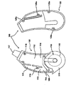
도 1은 종래의 리시버가 본체에 내장된 귀걸이형 보청기를 나타낸 도면이다.
종래 기술에 따른 귀걸이형 보청기는 도 1에 도시된 바와 같이, 마이크로폰(5)과 리시버(7)가 본체(1)에 내장되어 있고 리시버(7)에서 재생된 소리가 후크형관(4)과 사운드튜브(3)등을 통해 폐쇄형 이어팁(2)으로 전달되어 환자가 듣게 되는데, 이 경우 전달되는 경로가 복잡하고 길게 되어있어 중간에 음에 대한 손실 및 왜곡이 심해지고 마이크로폰(5)과 리시버(7)가 본체(1)에 가까이 위치한 관계로 간섭도 심해져 환자가 원래 소리를 정확하게 들기 어려운 단점이 있다.
아울러, 종래 기술에 따른 귀걸이형 보청기는, 마이크로폰(5)과 리시버(7) 등이 모두 본체(1)에 내장되어 있어 자체 음향 피드백이 발생하는 문제점이 있을 뿐만 아니라, 리시버(7)에서 나오는 음향이 사운드 튜브(3)를 통해 귀에 삽입하는 이어팁(2)으로 전달되므로 조금만 소리를 크게 증폭하여도 빈번하게 음향 피드백이 발생하는 문제점이 있다.
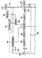
도 2는 종래의 리시버가 귓속에 삽입되는 보청기 쉘에 내장된 RIC(receiver in the canal) 타입 귀걸이형 보청기를 나타낸 도면이다.
도 1에 도시된 바와 같은 귀걸이형 보청기에서 발생되는 음향 피드백을 방지하기 위해서, 종래에 도 2에 도시된 바와 같은 RIC 타입의 귀걸이형 보청기가 제안되어 널리 사용되고 있다.
이와 같은 RIC 타입의 귀걸이형 보청기는, 음향처리수단으로부터 리이드 선(11)을 통해서 음향신호를 출력하는 리시버(12)가 리시버 튜브(13) 내에 끼워지고 리시버 튜브(13)가 귓속에 삽입되는 보청기 쉘(20)에 수용되도록 구성된다.
이러한 RIC 타입의 귀걸이형 보청기는, 리이드 선(11)의 길이가 제조시에 일률적으로 정해지기 때문에 귀의 크기가 제 각각인 사용자들이 착용하는데 불편한 문제점이 있고, 리시버(12)가 외이도 안으로 삽입되어 있기 때문에 귀지와 땀에 의한 부식으로 고장이 빈번하게 발생되는 문제점이 있다.
도 2에서, 미설명 부호 14는 리시버 튜브(13) 내로 귀지가 인입되는 것을 방지하기 위한 귀지인입방지부재이고, 15는 보청기 쉘(20)의 입구부를 덮도록 형성되는 페이스 플레이트이며, 15a는 리시버 튜브(13)가 끼워지도록 페이스 플레이트(15)에 형성된 관통구멍이다.
본 발명은 전술한 바와 같은 종래의 여러 문제점들을 해결하기 위해 안출된 것으로서, 사용자에 따라 맞춤 착용을 할 수 있고, 음향 피드백 현상 및 리시버의 잦은 고장 문제를 해소할 수 있는 RIT(RECEIVER IN THE TUBE)를 사용한 귀걸이형 보청기를 제공하는데 그 목적이 있다.
상기와 같은 목적들을 달성하기 위하여, 본 발명은 마이크로폰(130), 인터페이스 소켓(140), 음향처리수단(200), 메모리버튼(150), 볼륨조절기(160), 배터리(170) 및 상기 배터리 전극부(180)가 수용되는 케이스(100); 상기 음향처리수단(200)에 일단이 연결된 리이드 선(210)을 통해서 음향신호를 출력하되, 상기 리이드 선(210)의 타단에 연결되어 소정 길이로 이루어진 리시버 튜브(302) 내에 끼워지는 리시버(300); 상기 리시버(300)에 하이레벨의 노이즈가 인가되지 않도록 상기 배터리(170)에서 리시버(300)에 공급되는 직류전압에 포함된 하이레벨의 노이즈를 필터링하는 제4 캐패시터(C4); 상기 리시버 튜브(302)에서 그 길이방향을 따라 상기 리시버(300)가 끼워지는 쪽과 반대쪽에 위치한 리시버 튜브(302)의 단부가 수용되며, 상기 리시버(300)로부터 출력되는 음향을 듣도록 귓속에 삽입되는 보청기 쉘(400); 상기 보청기 쉘(400)의 입구부를 덮는 페이스 플레이트(500); 및 상기 케이스(100)의 인출구멍(117)에서 인출되는 상기 리이드 선(210)의 외주면을 덮도록 일측이 상기 인출구멍(117)의 외주면에 끼워짐과 동시에, 타측이 귀에 걸려서 고정되도록 둥굴게 라운드되어 있는 귀걸이용 후크(600);를 포함하여 이루어지되, 상기 케이스(100)에 인접한 리시버 튜브(302)의 외면 둘레에는 길이 방향을 따라 일정 간격으로 복수의 표시부(T1,T2,T3)가 형성되는 것을 특징으로 하는 RIT(RECEIVER IN THE TUBE)를 사용한 귀걸이형 보청기를 제공한다.
이때, 상기 리이드 선(210)의 타단에 연결된 리시버(300)가 상기 리시버 튜브(302) 내에 끼워져 일정 위치에 고정된 경우, 상기 케이스(100)로부터 귓속에 삽입되는 보청기 쉘(400)까지의 길이가 사용자의 귀의 크기에 맞도록 상기 리시버 튜브(302)에 형성된 복수의 표시부(T1,T2,T3) 중 두 개 이상의 표시부를 따라 상기 리시버 튜브(302)를 절단한 다음 상기 리시버(300)가 끼워진 상태의 리시버 튜브(302)를 상기 보청기 쉘(400)에 연결된 리시버 튜브(302)에 연결하도록 이루어질 수 있다.
다른 구성으로, 상기 리시버 튜브(302) 내에 상기 리시버(300)를 끼우되, 상기 케이스(100)로부터 귓속에 삽입되는 보청기 쉘(400)까지의 길이가 사용자의 귀의 크기에 맞도록 상기 리시버 튜브(302)에서 상기 복수의 표시부(T1,T2,T3) 중 어느 하나의 표시부가 형성된 위치에 리시버(300)를 고정할 수도 있다.
한편, 상기 케이스(100)는 케이스 본체(110)와, 상기 케이스 본체(110)의 개구부를 체결볼트(90)에 의해 체결하여 덮도록 나사공(120a)이 형성된 덮개(120)로 구성되고, 상기 케이스 본체(110)에는 상기 마이크로폰(130)을 수용하는 제1 수용공간(111), 상기 음향처리수단(200)를 수용하는 제2 수용공간(112), 상기 메모리버튼(150)을 수용하는 제3 수용공간(113), 상기 볼륨조절기(160)를 수용하는 제4 수용공간(114), 상기 배터리(170)를 수용하는 제5 수용공간(115), 상기 배터리(170)의 양극 및 음극과 각각 접촉하는 배터리 전극부(180)를 수용하는 제6 수용공간(116), 상기 음향처리수단(200)으로부터 리시버(200)에 음향신호를 출력하는 리이드 선(210)이 외측으로 인출되는 인출구멍(117), 및 상기 케이스 본체(110)와 상기 덮개(120)를 결합하도록 체결볼트(90)용 나사공(118)이 형성된다.
아울러, 상기 음향처리수단(200)은 스위치(172)의 스위칭 온 시에 상기 배터리(170)에서 공급되는 직류전압을 받아 일정 직류전압으로 조정하여 출력하는 전압레귤레이터(202), 상기 전압레귤레이터(202)에서 일정 직류전압으로 조정된 직류전압에 포함된 하이레벨의 노이즈를 필터링해서 상기 마이크로폰(130)에 공급하는 제1 캐패시터(C1), 상기 마이크로폰(130)에 의해 수신된 음향신호를 받아 음향신호에 포함되어 있는 하이 레벨의 노이즈를 필터링하는 제2 캐패시터(C2), 상기 제2 캐패시터(C2)에서 하이 레벨의 노이즈가 필터링된 아날로그 음향신호를 받아 디지털 음향신호로 변환하는 A/D변환기(204), 상기 A/D변환기(204)에서 출력되는 디지털음향신호를 받아서 일정레벨로 증폭하는 증폭수단(206), 퍼스널컴퓨터로부터 상기 인터페이스 소켓(140)을 통해 뉴스청취 파라미터(M1), 음악청취 파라미터(M2), 대화청취 파라미터(M3) 및 소음 큰 장소에서의 대화청취 파라미터(M4)를 받아 인터페이스된 모드신호를 저장하는 EEPROM(208), 상기 메모리버튼(150)을 1회 내지 4회 눌렀을 경우 상기 뉴스청취 파라미터(M1), 음악청취 파라미터(M2), 대화청취 파라미터(M3) 및 소음 큰 장소에서의 대화청취 파라미터(M4) 중 해당하는 파라미터를 받음과 동시에 상기 증폭수단(206)에서 일정 레벨로 증폭된 디지털 음향신호를 받아서 증폭하여 합산하는 이퀄라이저(E), 상기 이퀄라이저(E)에서 증폭되고 합성된 디지털 음향신호를 아날로그 음향신호로 변환하는 D/A변환기(212), 상기 D/A변환기(212)에서 출력되는 아날로그 음향신호를 받아서 볼륨을 조절하여 출력하는 볼륨조절기(160), 상기 리시버(300)에 하이레벨의 노이즈가 인가되지 않도록 상기 배터리(170)에서 리시버(300)에 공급되는 직류전압에 포함된 하이레벨의 노이즈를 필터링는 제4 캐패시터(C4)로 구성된다.
전술한 과제의 해결수단에 의하면 본 발명은 다음과 같은 효과를 가진다.
본 발명은 리이드 선의 타단에 연결된 리시버를 리시버 튜브 내에 설치하고 리시버가 설치된 쪽과 반대쪽에 위치한 리시버 튜브의 단부만 보청기 쉘에 삽입되도록 함으로써, 음향 피드백 현상을 해소할 수 있는 효과가 있다.
또한, 본 발명은 리시버 튜브의 외면 둘레에 길이 방향을 따라 일정 간격으로 복수의 표시부를 형성하여 필요에 따라 리이드 선 또는 리시버 튜브의 길이를 조절할 수 있도록 함으로써, 사용자에 따라 맞춤 착용을 할 수 있는 효과가 있다.
아울러, 본 발명은 케이스 쪽에 인접한 리시버 튜브 내에 리시버를 끼우고, 보청기 쉘에는 리시버가 설치된 쪽과 반대쪽에 위치한 리시버 튜브의 단부만 수용되도록 함으로써, 리시버가 외이도에 삽입되도록 구성되어 귀지와 땀에 의한 부식으로 고장이 빈번하게 발생되는 종래의 문제점을 미연에 방지할 수 있는 효과가 있다.
도 1은 종래의 리시버가 본체에 내장된 귀걸이형 보청기를 나타낸 도면이다.
도 2는 종래의 리시버가 귓속에 삽입되는 보청기 쉘에 내장된 RIC(receiver in the canal) 타입 귀걸이형 보청기를 나타낸 도면이다.
도 3은 본 발명에 따른 RIT(RECEIVER IN THE TUBE)를 사용한 귀걸이형 보청기를 개략적으로 나타낸 도면이다.
도 4는 본 발명에 따른 RIT를 사용한 귀걸이형 보청기의 케이스 본체 내에 배터리, 볼륨조절기, 메모리버튼 및 마이크로폰을 배설한 상태를 개략적으로 나타낸 도면이다.
도 5는 본 발명에 따른 RIT를 사용한 귀걸이형 보청기의 구성 부품을 분해해서 나타낸 도면이다.
도 6은 본 발명에 따른 RIT를 사용한 귀걸이형 보청기의 케이스 본체와 덮개를 분해해서 나타낸 도면이다.
도 7은 본 발명에 따른 RIT를 사용한 귀걸이형 보청기에 채용되는 마이크로폰, 배터리 및 리시버가 접속된 음향처리수단의 회로 블록도이다.
이하, 본 발명에 따른 RIT를 사용한 귀걸이형 보청기의 바람직한 실시예를 첨부한 도면들에 의거하여 상세히 설명한다. 참고로, 본 명세서 및 청구범위에 사용된 용어와 단어는 통상적이거나 사전적인 의미로 한정해서 해석되어서는 아니되며, 발명자는 그 자신의 발명을 가장 최선의 방법으로 설명하기 위해 용어의 개념을 적절하게 정의할 수 있다는 원칙에 입각하여 본 발명의 기술적 사상에 부합하는 의미와 개념으로 해석해야만 한다. 또한, 본 명세서에 기재된 실시예와 도면에 도시된 구성은 본 발명의 가장 바람직한 일 실시예에 불과할 뿐이고, 본 발명의 기술적 사상을 모두 대변하는 것은 아니므로 본 출원시점에 있어서 이들을 대체할 수 있는 다양한 균등물과 변형예들이 있을 수 있음을 이해하여야 한다.
도 3 내지 도 6은 본 발명에 따른 RIT를 사용한 귀걸이형 보청기를 나타낸 도면들이고, 도 7은 본 발명에 따른 RIT를 사용한 귀걸이형 보청기에 채용되는 마이크로폰, 배터리 및 리시버가 접속된 음향처리수단의 회로 블록도이다.
본 발명에 따른 RIT를 사용한 귀걸이형 보청기는, 케이스(100), 리시버(300), 제4 캐패시터(C4), 보청기 쉘(400), 페이스 플레이트(500) 및 후크(600)를 포함하여 이루어진다.
케이스(100)는 마이크로폰(130), 인터페이스 소켓(140), 음향처리수단(200), 메모리버튼(150), 볼륨조절기(160), 배터리(170) 및 상기 배터리 전극부(180)가 수용되도록 형성된다.
리시버(300)는 음향처리수단(200)에 일단이 연결된 리이드 선(210)을 통해서 음향신호를 출력하는 것으로서, 리이드 선(210)의 타단에 연결되어 소정 길이로 이루어진 리시버 튜브(302) 내에 끼워진다.
제4 캐패시터(C4)는 리시버(300)에 하이레벨의 노이즈가 인가되지 않도록 배터리(170)에서 리시버(300)에 공급되는 직류전압에 포함된 하이레벨의 노이즈를 필터링한다.
보청기 쉘(400)은 리시버 튜브(302)에서 그 길이방향을 따라 리시버(300)가 끼워지는 쪽과 반대쪽에 위치한 리시버 튜브(302)의 단부가 수용되며, 리시버(300)로부터 출력되는 음향을 듣도록 귓속에 삽입된다.
즉, 본 발명은 종래에서와 같이 리시버 튜브 내에 삽입된 리시버가 보청기 쉘에 수용되는 RIC(receiver in the canal) 타입과 달리, 리시버가 끼워진 쪽과 반대쪽에 위치한 리시버 튜브의 단부만 수용되는 RIT(receiver in the tubing) 타입의 귀걸이형 보청기에 대한 것이다.
페이스 플레이트(500)는 보청기 쉘(400)의 입구부를 덮도록 형성된다.
후크(600)는 케이스(100)의 인출구멍(117)에서 인출되는 리이드 선(210)의 외주면을 덮도록 일측이 상기 인출구멍(117)의 외주면에 끼워짐과 동시에, 타측이 귀에 걸려서 고정되도록 둥굴게 라운드되어 있다.
이때, 케이스(100)에 인접한 리시버 튜브(302)의 외면 둘레에는 길이 방향을 따라 일정 간격으로 복수의 표시부(T1,T2,T3)가 형성되는데, 리이드 선(210)의 타단에 연결된 리시버(300)가 리시버 튜브(302) 내에 끼워져 일정 위치에 고정된 경우, 케이스(100)로부터 귓속에 삽입되는 보청기 쉘(400)까지의 길이가 사용자의 귀의 크기에 맞도록 리시버 튜브(302)에 형성된 복수의 표시부(T1,T2,T3) 중 두 개 이상의 표시부를 따라 리시버 튜브(302)를 절단한 다음 리시버(300)가 끼워진 상태의 리시버 튜브(302)를 보청기 쉘(400)에 연결된 리시버 튜브(302)에 연결하도록 이루어질 수 있다.
이 경우, 리시버(300)가 끼워진 상태의 리시버 튜브(302)의 단부와 보청기 쉘(400)에 연결된 리시버 튜브(302)의 단부가 상호 대응되게 이루어지고, 상기 두 개의 단부 중 적어도 어느 하나의 단부에 접착제를 바른 다음 서로 연결하게 되면 견고하게 고정될 수 있다.
즉, 리시버 튜브(302)는 제조 공정에서 일정한 길이로 제조되고, 이러한 리시버 튜브(302)를 길이방향으로 3등분해서 외면 둘레에 T1, T2, T3로 표시를 한다.
이는 귀 뒤쪽에 위치하게 되는 케이스(100)에서 외이도로 삽입되는 보청기 쉘(400) 사이의 길이가 사람들 마다 다르기 때문에 제조시 리시버 튜브(302)의 외면에 3가지 길이로 표준화한 T1, T2, T3 표시를 한 표시부를 형성한 후 두 개 이상의 표시부를 따라 리시버 튜브(302)를 잘라내어 리시버 튜브(302)의 길이를 조절하기 위한 것이다.
이처럼 본 발명은 사용자에 따라 맞춤 착용을 할 수 있는 장점이 있다.
다른 구성으로, 케이스(100)에 인접한 리시버 튜브(302) 내에 리시버(300)를 끼우되, 케이스(100)로부터 귓속에 삽입되는 보청기 쉘(400)까지의 길이가 사용자의 귀의 크기에 맞도록 리시버 튜브(302)에서 복수의 표시부(T1,T2,T3) 중 어느 하나의 표시부가 형성된 위치에 리시버(300)를 고정할 수도 있다.
즉, 리시버 튜브(302)는 제조 공정에서 일정한 길이로 제조되고, 이러한 리시버 튜브(302)를 길이방향으로 3등분해서 외면 둘레에 T1, T2, T3로 표시를 한다.
이때, 리시버(300)를 리이드 선(210)과 같이 리시버 튜브(302) 내로 삽입하여 T1, T2, 또는 T3로 표시된 위치에 리시버(300)를 고정시킨다.
리시버(300)의 끝에 접착제를 바른 후에 리시버 튜브(302) 안으로 리이드 선과 함께 천천히 삽입시키고 수분 정도 지나면 완전히 고정되게 된다.
이처럼 리시버 튜브(302)의 길이를 일정하게 한 뒤, 리시버 튜브(302) 내의 리시버(300)의 위치를 변화시키면 리시버(300)의 음출구에서부터 고막까지의 거리가 달라지는데, 이때 공명 효과에 의해 400 Hz 이하의 저음의 강도가 주파수 대역 별로 달라지게 된다.
리시버(300)가 리시버 튜브(302) 내에서 외이도에 가까워 질수록 공명 주파수 대역이 200 내지 400 Hz 고주파수로 높아지고, 반대로 리시버(300)가 케이스(100)에 가까워 질수록 공명 주파수 대역이 50 내지 200 Hz 주파수로 낮아지게 된다.
노인성 난청을 가진 사람들의 대부분이 저주파수 대역보다는 고주파수 대역의 소리를 잘 못 듣게 되는데, 케이스(100)에서의 증폭은 주로 고주파수 대역을 조절하게 되고, 리시버 튜브(302) 내의 리시버(300) 위치를 사용자에 따라 변경하게 되면 저주파수 대역에서의 증폭 효과를 조절할 수 있게 된다.
한편, 케이스(100)는 케이스 본체(110)와, 케이스 본체(110)의 개구부를 체결볼트(90)에 의해 체결하여 덮도록 나사공(120a)이 형성된 덮개(120)로 구성되고, 케이스 본체(110)에는 마이크로폰(130)을 수용하는 제1 수용공간(111), 음향처리수단(200)를 수용하는 제2 수용공간(112), 메모리버튼(150)을 수용하는 제3 수용공간(113), 볼륨조절기(160)를 수용하는 제4 수용공간(114), 배터리(170)를 수용하는 제5 수용공간(115), 배터리(170)의 양극 및 음극과 각각 접촉하는 배터리 전극부(180)를 수용하는 제6 수용공간(116), 음향처리수단(200)으로부터 리시버(200)에 음향신호를 출력하는 리이드 선(210)이 외측으로 인출되는 인출구멍(117), 및 케이스 본체(110)와 덮개(120)를 결합하도록 체결볼트(90)용 나사공(118)이 형성된다.
아울러, 음향처리수단(200)은 도 7에 도시된 바와 같이, 스위치(172)의 스위칭 온 시에 배터리(170)에서 공급되는 직류전압을 받아 일정 직류전압으로 조정하여 출력하는 전압레귤레이터(202), 전압레귤레이터(202)에서 일정 직류전압으로 조정된 직류전압에 포함된 하이레벨의 노이즈를 필터링해서 마이크로폰(130)에 공급하는 제1 캐패시터(C1), 마이크로폰(130)에 의해 수신된 음향신호를 받아 음향신호에 포함되어 있는 하이 레벨의 노이즈를 필터링하는 제2 캐패시터(C2), 제2 캐패시터(C2)에서 하이 레벨의 노이즈가 필터링된 아날로그 음향신호를 받아 디지털 음향신호로 변환하는 A/D변환기(204), A/D변환기(204)에서 출력되는 디지털음향신호를 받아서 일정레벨로 증폭하는 증폭수단(206), 퍼스널컴퓨터로부터 인터페이스 소켓(140)을 통해 뉴스청취 파라미터(M1), 음악청취 파라미터(M2), 대화청취 파라미터(M3) 및 소음 큰 장소에서의 대화청취 파라미터(M4)를 받아 인터페이스된 모드신호를 저장하는 EEPROM(208), 메모리버튼(150)을 1회 내지 4회 눌렀을 경우 뉴스청취 파라미터(M1), 음악청취 파라미터(M2), 대화청취 파라미터(M3) 및 소음 큰 장소에서의 대화청취 파라미터(M4) 중 해당하는 파라미터를 받음과 동시에 증폭수단(206)에서 일정 레벨로 증폭된 디지털 음향신호를 받아서 증폭하여 합산하는 이퀄라이저(E), 이퀄라이저(E)에서 증폭되고 합성된 디지털 음향신호를 아날로그 음향신호로 변환하는 D/A변환기(212), D/A변환기(212)에서 출력되는 아날로그 음향신호를 받아서 볼륨을 조절하여 출력하는 볼륨조절기(160), 리시버(300)에 하이레벨의 노이즈가 인가되지 않도록 배터리(170)에서 리시버(300)에 공급되는 직류전압에 포함된 하이레벨의 노이즈를 필터링는 제4 캐패시터(C4)로 구성된다.
여기서, 미설명부호 304는 리시버 튜브(302)의 선단부에 끼워져서 귀지가 리시버 튜브(302) 내로 유입되는 것을 방지하기 위한 귀지인입 방지부재이고, 504는 페이스 플레이트(500)의 외측에 연결되어 귓구멍에 삽입된 보청기 쉘(400)을 외부로 끌어낼 때 잡아당기는 줄이고, 이 줄(504)의 외측 끝에는 용이하게 잡아당길 수 있도록 둥그런 형상의 매듭(504a)이 형성되어 있다.
또한, 미설명 부호 119는 배터리를 덮는 덮개이다.
이하, 상술한 바와 같이 구성된 본 발명에 따른 RIT를 사용한 귀걸이형 보청기에 대한 작용 및 효과에 대하여 설명한다.
먼저, 케이스(100)의 케이스 본체(110)에 형성된 제1 수용공간(111) 내에 마이크로폰(130)을 배설하고, 제2 수용공간(112) 내에 음향처리수단(200)을 배설하며, 제3 수용공간(113) 내에 메모리버튼(150)을 배설하고, 제4 수용공간(114) 내에 볼륨조절기(160)를 배설하며, 제5 수용공간(115) 내에 배터리(170) 배설하고, 제6 수용공간(116) 내에 배터리(170)의 양극 및 음극과 각각 접촉하는 배터리 전극부(180)를 배설하며, 덮개(120)에 도시하지 않은 퍼스널 컴퓨터에 접속되어 뉴스청취 파라미터(M1), 음악청취 파라미터(M2), 대화청취 파라미터(M3) 및 소음 큰 장소에서의 대화청취 파라미터(M4)를 받아 EEPROM(208)에 인터페이스된 모드신호를 저장하도록 인터페이스 소켓(140)을 설치한 다음, 케이스 본체(110)의 개구부를 덮개(120)로 씌우고 나서 케이스 본체(110)에 형성된 나사공(118)과 덮개(120)에 형성된 나사공(120a)을 대응되게 덮고, 체결볼트(90)에 의해 체결한다.
케이스 본체(110)와 덮개(120)에 의해 형성되는 인출구멍(117)을 통해서 인출되는 리이드 선(210)의 외주면과 인출구멍(117)을 귀걸이용 후크(600)로 외감시키고, 리이드 선(210)의 타측을 페이스 플레이트(500)에 형성된 관통구멍(502)에 끼우고, 리시버(300)를 연결한다.
그리고, 리시버 튜브(302)에 리시버(300)를 삽입하고, 리시버(300)가 설치된 쪽과 반대쪽에 위치한 리시버 튜브(302)의 단부를 보청기 쉘(400)내에 삽입한 후에, 상기 보청기쉘(400)의 개구부(미도시)에 페이스 플레이트(500)를 접착제 또는 볼트 등을 이용하여 설치한다.
이와 같이 본 발명의 귀걸이형 보청기를 조립한 다음, 귀걸이용 후크(600)를 귀에 걸면 케이스(100)가 귀의 뒤쪽에 위치하며, 이때 보청기 쉘(400)을 귀구멍에 삽입하고 나서, 스위치(172)를 스위칭 온 한다.
이에 따라, 배터리(170)에서 공급되는 직류전압에 포함된 하이레벨의 노이즈를 제4 캐패시터(C4)에서 필터링하여 리시버(300)에 공급함과 동시에, 배터리(170)에서 공급되는 직류전압을 전압레귤레이터(202)에서 받아 일정 직류전압으로 조정하여 이퀄라이저(210)에 동작전압을 공급하고, 전압레귤레이터(202)에서 일정 직류전압으로 조정된 직류전압에 포함된 하이레벨의 노이즈를 제1 캐패시터(C1)에서 필터링하여 마이크로폰(130)에 동작전원을 공급한다.
이 때, 마이크로폰(130)에 의해 수신된 음향신호는 제2 캐패시터(C2)에서 받아 음향신호에 포함되어 있는 하이 레벨의 노이즈를 필터링하여 A/D변환기(204)에 출력하면, A/D변환기(204)에서 하이 레벨의 노이즈가 필터링된 아날로그 음향신호를 받아 디지털 음향신호로 변환하고, A/D변환기(204)에서 출력되는 디지털 음향신호를 증폭수단(206)에서 받아 일정레벨로 증폭한다.
그리고, 도시하지 않은 퍼스널컴퓨터로부터 인터페이스 소켓(140)을 통해 뉴스를 청취하는 뉴스청취 파라미터(M1), 음악을 청취하는 음악청취 파라미터(M2), 대화를 청취하는 대화청취 파라미터(M3) 및 소음이 큰 장소에서의 대화청취하는 소음 큰 장소에서의 대화청취 파라미터(M4)를 받아 인터페이스된 모드신호가 EEPROM(208)에 저장되어 있으므로, 메모리버튼(150)을 눌러서 주위 환경에 따라 메모리버튼(150)을 1회 내지 4회중 어느 하나의 눌러서 본 발명의 귀걸이형 보청기를 착용한 착용자가 위치하는 환경에 맞는 파라미터를 선택하면 EEPROM(208)에서 메모리버튼(150)에 의해 선택된 M1 내지 M4 파라미터중 선택된 파라미터를 이퀄라이저(E)에 출력한다.
이에 따라, 이퀄라이저(E)에서는 증폭수단(206)에서 일정레벨로 증폭된 디지털 음향신호를 받음과 동시에, 메모리버튼(150)에 의해 설정된 뉴스청취 파라미터(M1), 음악청취 파라미터(M2), 대화청취 파라미터(M3) 또는 소음 큰 장소에서의 대화청취 파라미터(M4) 중 어느 하나의 모드를 EEPROM(208)으로부터 받아서 증폭하고 합산한다.
그리고, 이퀄라이저(E)에서 증폭되고 합성된 디지털 음향신호를 D/A변환기(212)에서 받아 아날로그 음향신호로 변환하고, D/A변환기(212)에서 출력되는 아날로그 음향신호를 볼륨조절기(160)에서 볼륨을 조절하여 리시버(300)에 출력한다.
따라서, 본 발명은 리이드 선(210)의 타단에 연결된 리시버(300)를 리시버 튜브(302) 내에 설치하고 리시버(300)가 설치된 쪽과 반대쪽에 위치한 리시버 튜브(302)의 단부만 보청기 쉘(400)에 삽입되도록 함으로써, 음향 피드백 현상을 해소하고, 리시버(300)가 외이도에 삽입되도록 구성되어 귀지와 땀에 의한 부식으로 고장이 빈번하게 발생되는 종래의 문제점을 미연에 방지할 수 있게 된다.
또한, 리시버 튜브(302)의 외면 둘레에 길이 방향을 따라 일정 간격으로 복수의 표시부(T1,T2,T3)를 형성하여 필요에 따라 리이드 선(210) 또는 리시버 튜브(302)의 길이를 조절할 수 있도록 함으로써, 사용자에 따라 맞춤 착용을 할 수 있는 장점이 있다.
이상에서 설명한 본 발명은 전술한 실시예 및 첨부된 도면들에 의해 한정되는 것은 아니며, 본 발명의 기술적 사상을 벗어나지 않는 범위 내에서 여러 가지 치환, 변형, 및 변경이 가능함은 본 발명이 속하는 기술분야에서 통상의 지식을 가진 자에게 있어 명백할 것이다.
Claims (5)
- 마이크로폰(130), 인터페이스 소켓(140), 음향처리수단(200), 메모리버튼(150), 볼륨조절기(160), 배터리(170) 및 상기 배터리 전극부(180)가 수용되는 케이스(100);상기 음향처리수단(200)에 일단이 연결된 리이드 선(210)을 통해서 음향신호를 출력하되, 상기 리이드 선(210)의 타단에 연결되어 소정 길이로 이루어진 리시버 튜브(302) 내에 끼워지는 리시버(300);상기 리시버(300)에 하이레벨의 노이즈가 인가되지 않도록 상기 배터리(170)에서 리시버(300)에 공급되는 직류전압에 포함된 하이레벨의 노이즈를 필터링하는 제4 캐패시터(C4);상기 리시버 튜브(302)에서 그 길이방향을 따라 상기 리시버(300)가 끼워지는 쪽과 반대쪽에 위치한 리시버 튜브(302)의 단부가 수용되며, 상기 리시버(300)로부터 출력되는 음향을 듣도록 귓속에 삽입되는 보청기 쉘(400);상기 보청기 쉘(400)의 입구부를 덮는 페이스 플레이트(500); 및상기 케이스(100)의 인출구멍(117)에서 인출되는 상기 리이드 선(210)의 외주면을 덮도록 일측이 상기 인출구멍(117)의 외주면에 끼워짐과 동시에, 타측이 귀에 걸려서 고정되도록 둥굴게 라운드되어 있는 귀걸이용 후크(600);를 포함하여 이루어지되,상기 케이스에 인접한 리시버 튜브(302)의 외면 둘레에는 길이 방향을 따라 일정 간격으로 복수의 표시부(T1,T2,T3)가 형성되는 것을 특징으로 하는 RIT를 사용한 귀걸이형 보청기.
- 청구항 1에 있어서,상기 리이드 선(210)의 타단에 연결된 리시버(300)가 상기 리시버 튜브(302) 내에 끼워져 일정 위치에 고정된 경우, 상기 케이스(100)로부터 귓속에 삽입되는 보청기 쉘(400)까지의 길이가 사용자의 귀의 크기에 맞도록 상기 리시버 튜브(302)에 형성된 복수의 표시부(T1,T2,T3) 중 두 개 이상의 표시부를 따라 상기 리시버 튜브(302)를 절단한 다음 상기 리시버(300)가 끼워진 상태의 리시버 튜브(302)를 상기 보청기 쉘(400)에 연결된 리시버 튜브(302)에 연결하도록 이루어지는 것을 특징으로 하는 RIT를 사용한 귀걸이형 보청기.
- 청구항 1에 있어서,상기 리시버 튜브(302) 내에 상기 리시버(300)를 끼우되, 상기 케이스(100)로부터 귓속에 삽입되는 보청기 쉘(400)까지의 길이가 사용자의 귀의 크기에 맞도록 상기 리시버 튜브(302)에서 상기 복수의 표시부(T1,T2,T3) 중 어느 하나의 표시부가 형성된 위치에 리시버(300)를 고정하는 것을 특징으로 하는 RIT를 사용한 귀걸이형 보청기.
- 청구항 1에 있어서,상기 케이스(100)는 케이스 본체(110)와, 상기 케이스 본체(110)의 개구부를 체결볼트(90)에 의해 체결하여 덮도록 나사공(120a)이 형성된 덮개(120)로 구성되고,상기 케이스 본체(110)에는 상기 마이크로폰(130)을 수용하는 제1 수용공간(111), 상기 음향처리수단(200)를 수용하는 제2 수용공간(112), 상기 메모리버튼(150)을 수용하는 제3 수용공간(113), 상기 볼륨조절기(160)를 수용하는 제4 수용공간(114), 상기 배터리(170)를 수용하는 제5 수용공간(115), 상기 배터리(170)의 양극 및 음극과 각각 접촉하는 배터리 전극부(180)를 수용하는 제6 수용공간(116), 상기 음향처리수단(200)으로부터 리시버(200)에 음향신호를 출력하는 리이드 선(210)이 외측으로 인출되는 인출구멍(117), 및 상기 케이스 본체(110)와 상기 덮개(120)를 결합하도록 체결볼트(90)용 나사공(118)이 형성되는 것을 특징으로 하는 RIT를 사용한 귀걸이형 보청기.
- 청구항 1에 있어서,상기 음향처리수단(200)은 스위치(172)의 스위칭 온 시에 상기 배터리(170)에서 공급되는 직류전압을 받아 일정 직류전압으로 조정하여 출력하는 전압레귤레이터(202), 상기 전압레귤레이터(202)에서 일정 직류전압으로 조정된 직류전압에 포함된 하이레벨의 노이즈를 필터링해서 상기 마이크로폰(130)에 공급하는 제1 캐패시터(C1), 상기 마이크로폰(130)에 의해 수신된 음향신호를 받아 음향신호에 포함되어 있는 하이 레벨의 노이즈를 필터링하는 제2 캐패시터(C2), 상기 제2 캐패시터(C2)에서 하이 레벨의 노이즈가 필터링된 아날로그 음향신호를 받아 디지털 음향신호로 변환하는 A/D변환기(204), 상기 A/D변환기(204)에서 출력되는 디지털음향신호를 받아서 일정레벨로 증폭하는 증폭수단(206), 퍼스널컴퓨터로부터 상기 인터페이스 소켓(140)을 통해 뉴스청취 파라미터(M1), 음악청취 파라미터(M2), 대화청취 파라미터(M3) 및 소음 큰 장소에서의 대화청취 파라미터(M4)를 받아 인터페이스된 모드신호를 저장하는 EEPROM(208), 상기 메모리버튼(150)을 1회 내지 4회 눌렀을 경우 상기 뉴스청취 파라미터(M1), 음악청취 파라미터(M2), 대화청취 파라미터(M3) 및 소음 큰 장소에서의 대화청취 파라미터(M4) 중 해당하는 파라미터를 받음과 동시에 상기 증폭수단(206)에서 일정 레벨로 증폭된 디지털 음향신호를 받아서 증폭하여 합산하는 이퀄라이저(E), 상기 이퀄라이저(E)에서 증폭되고 합성된 디지털 음향신호를 아날로그 음향신호로 변환하는 D/A변환기(212), 상기 D/A변환기(212)에서 출력되는 아날로그 음향신호를 받아서 볼륨을 조절하여 출력하는 볼륨조절기(160), 상기 리시버(300)에 하이레벨의 노이즈가 인가되지 않도록 상기 배터리(170)에서 리시버(300)에 공급되는 직류전압에 포함된 하이레벨의 노이즈를 필터링는 제4 캐패시터(C4)로 구성되는 것을 특징으로 하는 RIT를 사용한 귀걸이형 보청기.
Priority Applications (1)
| Application Number | Priority Date | Filing Date | Title |
|---|---|---|---|
| US16/480,410 US11323824B2 (en) | 2018-07-04 | 2018-08-31 | Earring hearing aid using RIT |
Applications Claiming Priority (2)
| Application Number | Priority Date | Filing Date | Title |
|---|---|---|---|
| KR1020180077395A KR102023456B1 (ko) | 2018-07-04 | 2018-07-04 | Rit를 사용한 귀걸이형 보청기 |
| KR10-2018-0077395 | 2018-07-04 |
Publications (1)
| Publication Number | Publication Date |
|---|---|
| WO2020009267A1 true WO2020009267A1 (ko) | 2020-01-09 |
Family
ID=68578168
Family Applications (1)
| Application Number | Title | Priority Date | Filing Date |
|---|---|---|---|
| PCT/KR2018/010133 Ceased WO2020009267A1 (ko) | 2018-07-04 | 2018-08-31 | Rit를 사용한 귀걸이형 보청기 |
Country Status (3)
| Country | Link |
|---|---|
| US (1) | US11323824B2 (ko) |
| KR (1) | KR102023456B1 (ko) |
| WO (1) | WO2020009267A1 (ko) |
Families Citing this family (9)
| Publication number | Priority date | Publication date | Assignee | Title |
|---|---|---|---|---|
| USD947812S1 (en) * | 2021-04-26 | 2022-04-05 | Shenzhenshi Annso Technology Co., Ltd | Wireless earphone |
| USD965556S1 (en) * | 2021-09-08 | 2022-10-04 | Shenzhen Quanmeng Technology Co., Ltd. | Earphone |
| USD962195S1 (en) * | 2021-09-19 | 2022-08-30 | Xiaochun Liang | Earphones |
| USD1025953S1 (en) * | 2022-06-08 | 2024-05-07 | Yealink (Xiamen) Network Technology Co., Ltd. | Audio headset |
| KR20240000779U (ko) | 2022-11-01 | 2024-05-08 | 김신혜 | 청력 보조기구 |
| USD1051093S1 (en) * | 2023-01-16 | 2024-11-12 | Shenzhen Fushike Electronic Co., Ltd | Wireless earphone |
| KR102665817B1 (ko) | 2023-06-22 | 2024-05-14 | 최서윤 | 사용자 커스터마이징이 가능한 보청기 |
| USD1094331S1 (en) * | 2023-08-18 | 2025-09-23 | Shenzhen Haoyi Electronic Technology Co., Ltd. | Earphone |
| USD1113814S1 (en) | 2023-09-19 | 2026-02-17 | Gn Audio A/S | Behind the ear headset |
Citations (5)
| Publication number | Priority date | Publication date | Assignee | Title |
|---|---|---|---|---|
| JPH1056698A (ja) * | 1996-08-12 | 1998-02-24 | Sony Corp | 電気音響変換装置 |
| KR20110051237A (ko) * | 2008-10-10 | 2011-05-17 | 비덱스 에이/에스 | 외이 수신기용 탄력성 쉘 |
| US20140195848A1 (en) * | 2013-01-08 | 2014-07-10 | Symantec, Inc. | Methods and systems for instant restore of system volume |
| KR101610884B1 (ko) * | 2014-06-26 | 2016-04-08 | 주식회사 비에스엘 | 방향 또는 길이 조절이 가능한 보청기 이어 팁 |
| KR101759919B1 (ko) * | 2016-07-26 | 2017-07-31 | (주)알고코리아 | 스마트 기기를 이용한 보청장치의 소음 및 휘드백 제거 장치 및 그 제공 방법 |
Family Cites Families (7)
| Publication number | Priority date | Publication date | Assignee | Title |
|---|---|---|---|---|
| KR200202012Y1 (ko) * | 2000-04-18 | 2000-11-01 | 박병준 | 길이 및 각도가 표시된 배관자재 |
| US7715578B2 (en) * | 2005-11-30 | 2010-05-11 | Research In Motion Limited | Hearing aid having improved RF immunity to RF electromagnetic interference produced from a wireless communications device |
| KR100875047B1 (ko) * | 2006-11-29 | 2008-12-19 | 권유정 | 귀걸이형 보청기 |
| EP2206202A1 (en) * | 2007-10-16 | 2010-07-14 | Estron A/S | An electrical connector for a hearing device |
| KR101169888B1 (ko) | 2011-01-26 | 2012-07-31 | 이승택 | 귀걸이 형 보청기 |
| US9237404B2 (en) | 2012-12-28 | 2016-01-12 | Gn Resound A/S | Dipole antenna for a hearing aid |
| EP2908558A1 (en) * | 2014-02-13 | 2015-08-19 | Siemens Medical Instruments Pte. Ltd. | Life tube adaptor for hearing aid |
-
2018
- 2018-07-04 KR KR1020180077395A patent/KR102023456B1/ko active Active
- 2018-08-31 US US16/480,410 patent/US11323824B2/en active Active
- 2018-08-31 WO PCT/KR2018/010133 patent/WO2020009267A1/ko not_active Ceased
Patent Citations (5)
| Publication number | Priority date | Publication date | Assignee | Title |
|---|---|---|---|---|
| JPH1056698A (ja) * | 1996-08-12 | 1998-02-24 | Sony Corp | 電気音響変換装置 |
| KR20110051237A (ko) * | 2008-10-10 | 2011-05-17 | 비덱스 에이/에스 | 외이 수신기용 탄력성 쉘 |
| US20140195848A1 (en) * | 2013-01-08 | 2014-07-10 | Symantec, Inc. | Methods and systems for instant restore of system volume |
| KR101610884B1 (ko) * | 2014-06-26 | 2016-04-08 | 주식회사 비에스엘 | 방향 또는 길이 조절이 가능한 보청기 이어 팁 |
| KR101759919B1 (ko) * | 2016-07-26 | 2017-07-31 | (주)알고코리아 | 스마트 기기를 이용한 보청장치의 소음 및 휘드백 제거 장치 및 그 제공 방법 |
Also Published As
| Publication number | Publication date |
|---|---|
| US11323824B2 (en) | 2022-05-03 |
| US20210337318A1 (en) | 2021-10-28 |
| KR102023456B1 (ko) | 2019-11-04 |
Similar Documents
| Publication | Publication Date | Title |
|---|---|---|
| WO2020009267A1 (ko) | Rit를 사용한 귀걸이형 보청기 | |
| US8699734B1 (en) | Dual microphone EAS system that prevents feedback | |
| US8257243B2 (en) | Frequency altered feedback for treating non-stuttering pathologies | |
| US7043040B2 (en) | Hearing aid apparatus | |
| KR100462116B1 (ko) | 청각 자극기 장치와 방법 | |
| CN111669691B (zh) | 包括传感器配置检测器的听力装置 | |
| US9955270B2 (en) | Bone conduction device fitting | |
| US20060177799A9 (en) | Methods and devices for treating non-stuttering speech-language disorders using delayed auditory feedback | |
| US20070206825A1 (en) | Noise reduction circuit for hearing aid | |
| CN108206979B (zh) | 一种多功能骨传导助听系统及其使用方法 | |
| US9408006B2 (en) | Systems and methods for facilitating electroacoustic stimulation using an off-the-ear sound processor module | |
| US8437859B1 (en) | Dual microphone EAS system that prevents feedback | |
| KR101169888B1 (ko) | 귀걸이 형 보청기 | |
| US9901736B2 (en) | Cochlea hearing aid fixed on eardrum | |
| EP2835983A1 (en) | Hearing instrument presenting environmental sounds | |
| MOHAMAD et al. | An Innovation of Hearing Aid | |
| CN2436102Y (zh) | 多功能袖珍电子听诊器 | |
| Voon et al. | Development of Digital Pseudo Binaural Hearing Aid | |
| ALASHI | DESIGN AND CONSTRUCTION OF HEARING AID | |
| WO2001089263A1 (en) | Portable bone conduction and sound amplifying hearing aid | |
| Morley | to obtain superior frequency response and ease of fitting. These imple | |
| JPH0623398U (ja) | 難聴者用音声伝達装置 |
Legal Events
| Date | Code | Title | Description |
|---|---|---|---|
| 121 | Ep: the epo has been informed by wipo that ep was designated in this application |
Ref document number: 18925063 Country of ref document: EP Kind code of ref document: A1 |
|
| NENP | Non-entry into the national phase |
Ref country code: DE |
|
| 122 | Ep: pct application non-entry in european phase |
Ref document number: 18925063 Country of ref document: EP Kind code of ref document: A1 |