WO2020012585A1 - Dispositif de ligature - Google Patents
Dispositif de ligature Download PDFInfo
- Publication number
- WO2020012585A1 WO2020012585A1 PCT/JP2018/026228 JP2018026228W WO2020012585A1 WO 2020012585 A1 WO2020012585 A1 WO 2020012585A1 JP 2018026228 W JP2018026228 W JP 2018026228W WO 2020012585 A1 WO2020012585 A1 WO 2020012585A1
- Authority
- WO
- WIPO (PCT)
- Prior art keywords
- distal end
- ligating
- main body
- opening
- fluid supply
- Prior art date
- Legal status (The legal status is an assumption and is not a legal conclusion. Google has not performed a legal analysis and makes no representation as to the accuracy of the status listed.)
- Ceased
Links
Images








Classifications
-
- A—HUMAN NECESSITIES
- A61—MEDICAL OR VETERINARY SCIENCE; HYGIENE
- A61B—DIAGNOSIS; SURGERY; IDENTIFICATION
- A61B17/00—Surgical instruments, devices or methods
- A61B17/12—Surgical instruments, devices or methods for ligaturing or otherwise compressing tubular parts of the body, e.g. blood vessels or umbilical cord
- A61B17/12009—Implements for ligaturing other than by clamps or clips, e.g. using a loop with a slip knot
- A61B17/12013—Implements for ligaturing other than by clamps or clips, e.g. using a loop with a slip knot for use in minimally invasive surgery, e.g. endoscopic surgery
-
- A—HUMAN NECESSITIES
- A61—MEDICAL OR VETERINARY SCIENCE; HYGIENE
- A61B—DIAGNOSIS; SURGERY; IDENTIFICATION
- A61B17/00—Surgical instruments, devices or methods
- A61B17/00234—Surgical instruments, devices or methods for minimally invasive surgery
- A61B2017/00292—Surgical instruments, devices or methods for minimally invasive surgery mounted on or guided by flexible, e.g. catheter-like, means
- A61B2017/00296—Surgical instruments, devices or methods for minimally invasive surgery mounted on or guided by flexible, e.g. catheter-like, means mounted on an endoscope
-
- A—HUMAN NECESSITIES
- A61—MEDICAL OR VETERINARY SCIENCE; HYGIENE
- A61B—DIAGNOSIS; SURGERY; IDENTIFICATION
- A61B17/00—Surgical instruments, devices or methods
- A61B2017/00535—Surgical instruments, devices or methods pneumatically or hydraulically operated
-
- A—HUMAN NECESSITIES
- A61—MEDICAL OR VETERINARY SCIENCE; HYGIENE
- A61B—DIAGNOSIS; SURGERY; IDENTIFICATION
- A61B17/00—Surgical instruments, devices or methods
- A61B2017/00831—Material properties
- A61B2017/00902—Material properties transparent or translucent
-
- A—HUMAN NECESSITIES
- A61—MEDICAL OR VETERINARY SCIENCE; HYGIENE
- A61B—DIAGNOSIS; SURGERY; IDENTIFICATION
- A61B17/00—Surgical instruments, devices or methods
- A61B2017/00982—General structural features
- A61B2017/00991—Telescopic means
-
- A—HUMAN NECESSITIES
- A61—MEDICAL OR VETERINARY SCIENCE; HYGIENE
- A61B—DIAGNOSIS; SURGERY; IDENTIFICATION
- A61B17/00—Surgical instruments, devices or methods
- A61B17/12—Surgical instruments, devices or methods for ligaturing or otherwise compressing tubular parts of the body, e.g. blood vessels or umbilical cord
- A61B17/12009—Implements for ligaturing other than by clamps or clips, e.g. using a loop with a slip knot
- A61B2017/12018—Elastic band ligators
-
- A—HUMAN NECESSITIES
- A61—MEDICAL OR VETERINARY SCIENCE; HYGIENE
- A61B—DIAGNOSIS; SURGERY; IDENTIFICATION
- A61B17/00—Surgical instruments, devices or methods
- A61B17/30—Surgical pincettes, i.e. surgical tweezers without pivotal connections
- A61B2017/306—Surgical pincettes, i.e. surgical tweezers without pivotal connections holding by means of suction
Definitions
- the present invention relates to a ligation device.
- a ligation device for ligating an affected part such as a diverticulum or a varicose vein formed in a patient's digestive tract or the like is known.
- Such a ligating device is disclosed, for example, in Patent Document 1.
- an affected part is ligated by driving a slide cylinder with a fluid and pushing out and removing an O-ring mounted on the inner cylinder with the slide cylinder.
- An object of the present invention is to provide a ligating device capable of reliably detaching a ligating ring from a main body.
- a ligating device has a cylindrical shape, is located at a distal end portion of an endoscope, and has a distal end portion protruding more distally than the distal end surface of the endoscope.
- a main body in which a first fluid supply passage having a first opening that opens to a front end surface or an outer peripheral surface of the front end portion is provided; and a main body in which the front end portion of the main body is closed so as to cover the first opening portion.
- a first ligating ring attached.
- a second fluid supply path having a second opening that opens in the distal end surface or the outer peripheral surface of the distal end portion is formed in the main body, and closes the second opening of the second fluid supply path.
- a second ligating ring may be mounted on the distal end portion of the main body.
- the distal end of the main body has a tapered shape that tapers toward a distal end, and the first opening of the first fluid supply path and the second opening of the second fluid supply path are formed by the main body.
- An opening may be formed on the outer peripheral surface of the tip.
- the main body has a cylindrical base portion, and a cylindrical sliding portion slidably provided with respect to the base portion by a fluid, and the first fluid supply path includes the sliding member.
- the first opening may be formed on the distal end surface or the outer peripheral surface of the sliding portion, and the first ligating ring may be attached to the sliding portion.
- the tip of the base may be tapered toward the tip.
- a second fluid supply path having a second opening that opens to the distal end surface or the outer peripheral surface thereof is formed in the sliding portion, and the second fluid supply path is configured to close the second opening of the second fluid supply path.
- a second ligating ring may be attached to the sliding portion.
- the distal end of the sliding portion has a tapered shape that tapers toward the distal end, and the first opening of the first fluid supply path and the second opening of the second fluid supply path are An opening may be formed in the outer peripheral surface of the tip portion of the sliding portion.
- the first opening has an annular shape coaxial with the cylindrical main body, and the first ligating ring is provided in the main body so as to close the annular first opening, A second ligating ring may be provided closer to the base end of the first opening than the first ligating ring.
- the main body has a cylindrical base portion, and a cylindrical sliding portion slidably provided with respect to the base portion by a fluid, and the first fluid supply path includes the sliding member.
- the first opening may be formed in a portion, and the first opening may be open at a distal end surface of the sliding portion, and the first opening may have an annular shape coaxial with the cylindrical sliding portion.
- the tip of the base may be tapered toward the tip.
- a projection with which the distal end of the endoscope distal end abuts may be provided on the inner peripheral surface of the main body.
- the main body may be made of a translucent material.
- a ligating device capable of reliably detaching the ligating ring from the main body.
- FIG. (A) is sectional drawing of the state which attached the device for ligation which concerns on 1st Embodiment to the endoscope
- (b) is the state which attached the device for ligation which concerns on 1st Embodiment to an endoscope.
- FIG. (A) is sectional drawing of the state which attached the ligation device which concerns on 2nd Embodiment to the endoscope
- (b) is the state which attached the ligation device which concerns on 2nd Embodiment to the endoscope.
- FIG. (A) is sectional drawing of the state which attached the device for ligation which concerns on 3rd Embodiment to an endoscope
- (b) is the state which attached the device for ligation which concerns on 3rd Embodiment to an endoscope.
- FIG. (A) is sectional drawing of the state which attached the device for ligation which concerns on 4th Embodiment to an endoscope
- (b) is the state which attached the device for ligation which concerns on 4th Embodiment to an endoscope.
- FIG. (A) is sectional drawing of the state which attached the device for ligation which concerns on 5th Embodiment to an endoscope
- (b) is the state which attached the device for ligation which concerns on 5th Embodiment to an endoscope.
- FIG. (A) is sectional drawing of the state which attached the device for ligation which concerns on 6th Embodiment to an endoscope
- (b) is the state which attached the device for ligation which concerns on 6th Embodiment to an endoscope.
- FIG. (A) is sectional drawing of the state which attached the ligating device which concerns on 7th Embodiment to the endoscope, and shows the state in which a sliding part is located in the base end side, (b) is 7th.
- FIG. 2 is a cross-sectional view of a state in which the ligation device according to the embodiment is mounted on an endoscope, and shows a state where a sliding portion is located on a distal end side.
- (A) is sectional drawing of the state which attached the ligating device which concerns on 8th Embodiment to the endoscope, and shows the state in which a sliding part is located in the base end side, (b) is 8th.
- FIG. 2 is a cross-sectional view of a state in which the ligation device according to the embodiment is mounted on an endoscope, and shows a state where a sliding portion is located on a distal end side.
- A is sectional drawing of the state which attached the ligating device which concerns on 9th Embodiment to the endoscope, and shows the state in which a sliding part is located in the base end side
- b is 9th.
- FIG. 2 is a cross-sectional view of a state in which the ligation device according to the embodiment is mounted on an endoscope, and shows a state where a sliding portion is located on a distal end side.
- FIG. 2 is a cross-sectional view of a state in which the ligation device according to the embodiment is mounted on an endoscope, and shows a state where a sliding portion is located on a distal end side.
- (A) is sectional drawing of the state which attached the ligation device which concerns on 11th Embodiment to the endoscope, and shows the state in which a sliding part is located in the base end side, (b) is 11th.
- FIG. 2 is a cross-sectional view of a state in which the ligation device according to the embodiment is mounted on an endoscope, and shows a state where a sliding portion is located on a distal end side.
- A is sectional drawing of the state which attached the ligating device which concerns on 12th Embodiment to the endoscope, and shows the state in which a sliding part is located in the base end side
- (b) is 12th.
- FIG. 2 is a cross-sectional view of a state in which the ligation device according to the embodiment is mounted on an endoscope, and shows a state where a sliding portion is located on a distal end side.
- 39 is a cross-sectional view of a state in which the ligation device according to the thirteenth embodiment is mounted on an endoscope, showing a state where a sliding portion is located on a proximal end side. It is sectional drawing of the state which attached the device for ligation which concerns on 14th Embodiment to the endoscope, and has shown the state in which the sliding part is located in the base end side. It is a partially cutaway sectional view of the ligation device provided with the endoscope part concerning a 15th embodiment.
- FIG. 1A is a cross-sectional view illustrating a state in which a ligation device 1 according to a first embodiment of the present invention is mounted on an endoscope 2, and FIG. It is a front view in the state where it attached.
- FIG. 1A shows only the distal end of the endoscope 2 on which the ligating device 1 is mounted.
- FIG. 1A shows only the distal end of the endoscope 2 on which the ligating device 1 is mounted.
- the right side in the figure is the distal side (distal side) to be inserted into the body, and the left side is the proximal side (hand side, proximal side).
- the endoscope 2 is formed with a forceps hole 2a for inserting forceps (not shown). It should be noted that the endoscope 2 shows its appearance and is not shown in a sectional view (the same applies to the following drawings).
- the ligating device 1 includes the mounting tube 3, the main body 10, the tube 4, and the first ligating ring 5.
- the mounting tube 3 has a tubular shape and is provided for fixing the ligating device 1 to the endoscope 2.
- the material constituting the mounting cylinder 3 is not particularly limited as long as it has a suitable flexibility that is detachable and securely fixed to the endoscope 2 and has biocompatibility.
- An elastic material such as natural rubber, synthetic rubber or thermoplastic elastomer can be used.
- the synthetic rubber include isoprene rubber, butadiene rubber, styrene / butadiene rubber, nitrile rubber, butyl rubber, ethylene / propylene rubber, acrylic rubber, fluorine rubber, silicone rubber, and the like.
- thermoplastic elastomer examples include a styrene-based elastomer, an olefin-based elastomer, a polyester-based elastomer, a polyurethane-based elastomer, and a polyamide-based elastomer.
- the main body 10 has a cylindrical shape, is connected to the distal end of the mounting cylinder 3, is located at the endoscope distal end 2b, and is attached to the endoscope distal end 2b in an airtight state or a liquid-tight state.
- the main body 10 has a distal end portion 11 protruding distally from the distal end surface 2c of the endoscope 2.
- the main body 10 has a first fluid supply path 12 extending along the axial direction thereof.
- the first fluid supply path 12 has a first opening 14 that opens to the distal end surface 13 of the main body 10.
- the distal end portion 11 of the main body 10 has an annular convex portion 15 located on the inner peripheral side of the first opening 14 and protruding toward the distal end side.
- a projection 17 projecting inward is provided on the inner peripheral surface 16 of the main body 10.
- the distal end of the distal end portion 2b of the endoscope abuts on the projection 17 in the axial direction.
- the distal end portion 11 and the distal end surface 2c of the endoscope 2 form a concave space 18.
- the material constituting the main body 10 is not particularly limited as long as it has the strength capable of withstanding the first ligating ring 5 and the biocompatibility, as described later, for example, metal Materials, resin materials, and ceramic materials can be used.
- metal materials include stainless steel, titanium, and nickel titanium alloys.
- the resin material include polyethylene, polypropylene, polyvinyl chloride, polystyrene, acrylic resin, phenol resin, melamine resin, polyimide, polyamide, polycarbonate, polyethersulfone, polyetheretherketone, and polytetrafluoroethylene.
- the ceramic material include glass and fine ceramics.
- the material constituting the main body 10 may be a translucent material, for example, polypropylene, polycarbonate, polyethersulfone, polyimide, or acrylic resin in order to keep a wide field of view at the time of treatment.
- the tube 4 extends from the distal end to the proximal end along the endoscope 2.
- a syringe (not shown) for sending a fluid such as air to the first fluid supply path 12 of the main body 10 is connected to a proximal end of the tube 4.
- the distal end of the tube 4 is air-tightly connected to the proximal end of the first fluid supply path 12.
- the material constituting the tube 4 is not particularly limited as long as it has flexibility enough to follow the deformation of the endoscope 2 and has biocompatibility.
- polyethylene, polypropylene, polyvinyl chloride And a fluororesin for example, polyethylene, polypropylene, polyvinyl chloride And a fluororesin.
- the first ligating ring 5 is an O-ring, and is mounted on the outer periphery of the convex portion 15 of the distal end portion 11 of the main body 10 so as to close the first opening 14 in an airtight state.
- the material constituting the first ligating ring 5 is not particularly limited as long as it extends sufficiently to be attachable to the distal end portion 11, has sufficient ligating force to necrosis the diverticulum, and has biocompatibility.
- an elastic material such as a natural rubber, a synthetic rubber, or a thermoplastic elastomer can be used.
- Examples of the synthetic rubber include isoprene rubber, butadiene rubber, styrene / butadiene rubber, nitrile rubber, butyl rubber, ethylene / propylene rubber, acrylic rubber, fluorine rubber, silicone rubber, and the like.
- Examples of the thermoplastic elastomer include a styrene-based elastomer, an olefin-based elastomer, a polyester-based elastomer, a polyurethane-based elastomer, and a polyamide-based elastomer.
- the material forming the first ligating ring 5 is, for example, gold, platinum, tungsten, or an alloy containing these elements (for example, a platinum-nickel alloy), or barium sulfate, bismuth subcarbonate, bismuth trioxide. , A radiopaque material such as bismuth oxychloride and bismuth subcarbonate, or a powder of a radiopaque material.
- the cross-sectional shape of the first ligating ring 5 is not limited to a circle, but may be another shape such as a rectangle.
- the color of the first ligating ring 5 is preferably a color such as black that stands out from the surrounding tissue.
- the total length of the ligating device 1 (the length from the front end of the main body 10 to the rear end of the mounting tube 3) is set to, for example, 20 to 25 mm.
- the main body 10 (the portion where the projection 17 is not provided) has, for example, an inner diameter of 8 to 16 mm and an outer diameter (maximum) of 10 to 20 mm.
- the endoscope 2 equipped with the ligation device 1 is inserted into the digestive tract, and the inside of the digestive tract is observed.
- the bleeding diverticulum is identified, the endoscope 2 and the ligating device 1 are brought close to the diverticulum, the diverticulum is suctioned through the forceps hole 2a, and the diverticulum becomes convex toward the endoscope 2.
- the diverticulum is positioned in the recessed space 18.
- the fluid is sent to the first fluid supply passage 12 of the main body 10 via the tube 4, and the first ligation ring 5 is detached from the main body 10 using the pressure of the fluid as a driving source.
- the sucked diverticulum is ligated by the first ligating ring 5.
- the endoscope 2 equipped with the ligation device 1 is taken out of the digestive tract. Thereafter, the ligated diverticulum is necrotic and discharged out of the body together with the first ligating ring 5.
- the first ligating ring 5 is attached to the distal end portion 11 of the main body 10 so as to close the first opening 14 in an airtight state.
- the first ligating ring 5 can be reliably detached from the main body 10 by using the pressure of the fluid flowing through the first fluid supply path 12 as a driving source.
- the inner peripheral surface 16 of the main body 10 is provided with a projection 17 with which the distal end of the endoscope distal end portion 2b contacts. Therefore, the projection 17 makes it possible to easily position the ligating device 1 with respect to the endoscope distal end portion 2b.
- the main body 10 By forming the main body 10 from a translucent material, a wide field of view at the time of the treatment by the endoscope 2 can be maintained.
- FIG. 2A is a cross-sectional view illustrating a state in which the ligation device 101 according to the second embodiment of the present invention is mounted on the endoscope 2, and FIG. It is a front view in the state where it attached.
- FIG. 2A shows only the distal end of the endoscope 2 on which the ligating device 101 is mounted.
- the right side in the figure is the distal end (distal side) to be inserted into the body, and the left side is the proximal side (hand side, proximal side).
- the same members as those of the ligating device 1 of the first embodiment are denoted by the same reference numerals, and detailed description thereof will be omitted.
- the ligating device 101 includes the mounting tube 3, the main body 20, the tube 4, and the first ligating ring 5.
- the main body 20 has a tubular shape, is connected to the distal end of the mounting cylinder 3, and is located at the endoscope distal end portion 2b.
- the main body 20 has a distal end portion 21 that projects more distally than the distal end surface 2c of the endoscope 2.
- the main body 20 has a first fluid supply passage 22 formed therein.
- the first fluid supply path 22 includes an axial flow path 22a extending from the base end of the main body 20 along the axial direction to the distal end portion 21 and a radial flow path 22b extending from the distal end of the axial flow path 22a to the outer peripheral surface 23 along the radial direction. And Therefore, the first fluid supply passage 22 has the first opening 24 that opens to the outer peripheral surface 23 of the main body 20.
- the inner peripheral surface 25 of the main body 20 is provided with a protrusion 26 projecting inward.
- the distal end of the endoscope distal end portion 2b abuts on the projection 26 in the axial direction.
- a concave space 27 is formed by the distal end portion 21 and the distal end surface 2c of the endoscope 2.
- the first ligating ring 5 is mounted on the outer peripheral surface 23 of the main body 20 so as to close the first opening 24 in an airtight state.
- the first ligation ring 5 is attached to the distal end portion 21 of the main body 20 so as to close the first opening 24 in an airtight state. Accordingly, the first ligating ring 5 can be reliably detached from the main body 20 using the pressure of the fluid flowing through the first fluid supply passage 22 as a driving source.
- FIG. 3A is a cross-sectional view illustrating a state in which the ligating device 201 according to the third embodiment of the present invention is mounted on the endoscope 2, and FIG. It is a front view in the state where it attached.
- FIG. 3A shows only the distal end of the endoscope 2 on which the ligating device 201 is mounted.
- the right side in the figure is the distal side (distal side) to be inserted into the body, and the left side is the proximal side (hand side, proximal side).
- the same members as those of the ligating device 1 of the first embodiment are denoted by the same reference numerals, and the detailed description is omitted.
- the ligating device 201 includes the mounting tube 3, the main body 30, the first tube 4a, the second tube 4b, the first ligating ring 5a, and the second ligating ring 5b.
- the main body 30 has a cylindrical shape, is connected to the distal end of the mounting cylinder 3, and is located at the distal end portion 2b of the endoscope.
- the main body 30 has a distal end portion 31 that projects more distally than the distal end surface 2c of the endoscope 2.
- An annular first concave portion 33a and an annular second concave portion 33b are formed in the distal end surface 32 of the distal end portion 31.
- the first recess 33a and the second recess 33b are coaxial with the main body 30 and have different diameters. The diameter of the first recess 33a is smaller than that of the second recess 33b.
- a first fluid supply path 34a and a second fluid supply path 34b extending in the axial direction are formed in the main body 30.
- the first fluid supply path 34a and the second fluid supply path 34b are formed at positions opposite to each other with respect to the axis.
- the first fluid supply passage 34a has a first opening 35a that opens to the distal end face 32 via the first recess 33a.
- the second fluid supply path 34b has a second opening 35b that opens to the distal end face 32 via the second recess 33b.
- the first tube 4a is connected to the base end of the first fluid supply path 34a, and the second tube 4b is connected to the base end of the second fluid supply path 34b.
- a projection 37 protruding inward is provided on the inner peripheral surface 36 of the main body 30.
- the distal end of the distal end portion 2b of the endoscope abuts on the protrusion 37 in the axial direction.
- the distal end portion 31 and the distal end surface 2c of the endoscope 2 form a concave space 38.
- the material forming the main body 30 is the same as the material forming the main body 10 of the first embodiment, and thus the detailed description thereof will be omitted with reference to the description of the first embodiment.
- a first ligating ring 5a is mounted in the first recess 33a so as to close the first opening 35a of the first fluid supply passage 34a in an airtight state.
- the second ligating ring 5b is mounted in the second recess 33b so as to close the second opening 35b of the second fluid supply path 34b in an airtight state.
- the first ligating ring 5a is attached to the distal end portion 31 of the main body 30 so as to close the first opening 35a in an airtight state, and the second opening 35b is airtightly closed.
- the second ligating ring 5b is attached to the distal end portion 31 of the main body 30 so as to close the ligature.
- FIG. 4A is a cross-sectional view illustrating a state in which the ligating device 301 according to the fourth embodiment of the present invention is mounted on the endoscope 2, and FIG. It is a front view in the state where it attached.
- FIG. 4A shows only the distal end portion of the endoscope 2 on which the ligating device 301 is mounted.
- the right side in the figure is the distal side (distal side) to be inserted into the body, and the left side is the proximal side (hand side, proximal side).
- the same members as those of the ligating device 1 of the first embodiment are denoted by the same reference numerals, and detailed description thereof will be omitted.
- the ligating device 301 includes the mounting tube 3, the main body 40, the first tube 4a, the second tube 4b, the first ligating ring 5a, and the second ligating ring 5b.
- the main body 40 has a cylindrical shape, is connected to the distal end of the mounting tube 3, and is located at the endoscope distal end portion 2b.
- the main body 40 has a distal end portion 41 protruding more distally than the distal end surface 2c of the endoscope 2.
- a first fluid supply path 42 and a second fluid supply path 43 are formed in the main body 40.
- the first fluid supply path 42 and the second fluid supply path 43 are formed at positions opposite to each other with respect to the axis.
- the first fluid supply channel 42 extends from the base end of the main body 40 to the distal end portion 41 along the axial direction to the distal end portion 41, and from the distal end of the first axial flow channel 42a to the outer peripheral surface 44 along the radial direction. And a first radial flow path 42b extending therefrom. Therefore, the first fluid supply path 42 has a first opening 45 a that opens to the outer peripheral surface 44 of the distal end 41 of the main body 40.
- the first tube 4a is connected to the base end of the first fluid supply path 42.
- the second fluid supply channel 43 extends from the base end of the main body 40 along the axial direction to the distal end portion 41, and from the distal end of the second axial flow channel 43a to the outer peripheral surface 44 along the radial direction. And a second diameter channel 43b extending. Therefore, the second fluid supply passage 43 has a second opening 45 b that opens in the outer peripheral surface 44 of the distal end portion 41 of the main body 40.
- the second diameter channel 43b is located closer to the base end in the axial direction than the first diameter channel 42b.
- the second tube 4b is connected to the base end of the second fluid supply path 43.
- a projection 47 protruding inward is provided on the inner peripheral surface 46 of the main body 40.
- the tip of the endoscope tip 2b abuts on the projection 47 in the axial direction.
- a concave space 48 is formed by the distal end portion 41 and the distal end surface 2c of the endoscope 2.
- the first ligating ring 5a is mounted so as to close the first opening 45a of the first fluid supply path 42 in an airtight state.
- the second ligating ring 5b is mounted so as to close the second opening 45b of the second fluid supply path 43 in an airtight state.
- the second ligation ring 5b is located closer to the base end than the first ligation ring 5a.
- the first ligating ring 5a is attached to the distal end portion 41 of the main body 40 so as to close the first opening 45a in an airtight state, and the second opening 45b is airtightly closed.
- the second ligating ring 5b is attached to the distal end portion 41 of the main body 40 so as to be closed.
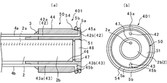
- FIG. 5A is a cross-sectional view showing a state in which the ligating device 401 according to the fifth embodiment of the present invention is mounted on the endoscope 2, and FIG. It is a front view in the state where it attached.
- FIG. 5A shows only the distal end of the endoscope 2 on which the ligating device 401 is mounted.
- the right side in the figure is the distal end side (distal side) to be inserted into the body, and the left side is the proximal end side (hand side, proximal side).
- the same members as those of the ligating device 301 of the fourth embodiment are denoted by the same reference numerals, and the detailed description is omitted.
- the ligating device 401 includes the mounting tube 3, the main body 50, the first tube 4a, the second tube 4b, the first ligating ring 5a, and the second ligating ring 5b.
- the structure of the main body 50 is substantially the same as the structure of the main body 40 of the fourth embodiment. Therefore, the same components are denoted by the same reference numerals, and only different configurations will be described.
- the distal end portion 51 of the main body 50 has a tapered shape that tapers toward the distal end.
- the first opening 45a of the first fluid supply passage 42 opens in the outer peripheral surface 54 of the distal end 51 of the main body 50, and the second opening 45b of the second fluid supply passage 43 connects to the distal end 51 of the main body 50. Is opened on the outer peripheral surface 54.
- the first ligating ring 5a is mounted so as to close the first opening 45a of the first fluid supply path 42 in an airtight state.
- the second ligating ring 5b is mounted so as to close the second opening 45b of the second fluid supply path 43 in an airtight state.
- the first opening 45a and the second opening 45b are opened in the outer peripheral surface 54 of the tapered tip portion 51, and the first ligating ring 5a and the second ligating ring Since 5b is attached to the outer peripheral surface 54, the first ligating ring 5a and the second ligating ring 5b can be more reliably detached from the main body.
- FIG. 6A is a cross-sectional view illustrating a state in which the ligating device 501 according to the sixth embodiment of the present invention is mounted on the endoscope 2
- FIG. 6B is a diagram illustrating the ligating device 501 mounted on the endoscope 2. It is a front view in the state where it attached.
- FIG. 6A shows only the distal end of the endoscope 2 to which the ligating device 501 is attached.
- the right side in the figure is the distal side (distal side) to be inserted into the body, and the left side is the proximal side (hand side, proximal side).
- the same members as those of the ligating device 1 of the first embodiment are denoted by the same reference numerals, and detailed description is omitted.
- the ligating device 501 includes the mounting tube 3, the main body 60, the tube 4, the first ligating ring 5a, and the second ligating ring 5b.
- the main body 60 has a tubular shape, is connected to the distal end of the mounting tube 3, and is located at the distal end portion 2b of the endoscope.
- the main body 60 has a distal end portion 61 protruding more distally than the distal end surface 2c of the endoscope 2.
- the main body 60 has a first fluid supply path 62 extending along the axial direction thereof.
- the first fluid supply path 62 is formed so as to form a cylindrical shape coaxial with the main body 60, and has an annular first opening 64 that is open at the distal end surface 63 of the main body 60 and is coaxial with the main body 60.
- the distal end portion 61 of the main body 60 is located on the inner peripheral side of the first opening 64 and has an annular convex portion 65 protruding toward the distal end side.
- the inner peripheral surface 66 of the main body 60 is provided with a protrusion 67 projecting inward.
- the distal end of the distal end portion 2b of the endoscope abuts on the protrusion 67 in the axial direction.
- a concave space 68 is formed by the distal end portion 61 and the distal end surface 2c of the endoscope 2.
- the first ligating ring 5a is mounted on the outer periphery of the convex portion 15 of the distal end portion 11 of the main body 60 so as to close the annular first opening 64 in an airtight state.
- the second ligating ring 5b is attached to the proximal end of the first ligating ring 5a at the first opening 64.
- the fluid is sent to the first fluid supply path 62 of the main body 60 via the tube 4, and the pressure of the fluid is used as a drive source to push the second ligation ring 5b.
- the first ligating ring 5a is pushed out, and the first ligating ring 5a can be detached from the main body 60.
- the second ligating ring 5b can be detached from the main body 60 by pressing the second ligating ring 5b using the pressure of the fluid as a driving source.
- the ligation process can be performed continuously without taking the ligation device 501 out of the body.
- the distal end portion 61 of the main body 60 may be configured to cover the outer periphery of the first ligating ring 5a.
- a stopper 69 a that protrudes inward may be provided at a distal end portion 61 of the main body 60 at a distal end of an outer peripheral portion of a portion where the first fluid supply passage 62 is formed.
- a stopper 69b that protrudes outward may be provided at a distal end portion 61 of the main body 60 at a distal end of an inner peripheral portion of a portion where the first fluid supply passage 62 is formed.
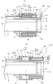
- FIG. 7A is a cross-sectional view illustrating a state in which the ligating device 601 according to the seventh embodiment of the present invention is mounted on the endoscope 2, and illustrates a state where the sliding portion 72 is located on the proximal end side.
- (B) is a cross-sectional view showing a state in which the ligating device 601 is mounted on the endoscope 2, and shows a state in which the sliding portion 72 is located on the distal end side.
- FIGS. 7A and 7B show only the distal end of the endoscope 2 to which the ligating device 601 is attached.
- the right side in the drawing is the distal side (distal side) to be inserted into the body, and the left side is the proximal side (hand side, proximal side).
- the same members as those of the ligating device 1 of the first embodiment are denoted by the same reference numerals, and detailed description is omitted.
- the ligating device 601 includes the mounting tube 3, the main body 70, the first tube 4a, the second tube 4b, and the first ligating ring 5.
- the main body 70 has a cylindrical base 71 and a cylindrical sliding part 72, is connected to the distal end of the mounting tube 3, and is located at the endoscope distal end 2b.
- the base portion 71 has a distal end portion 71a projecting distally from the distal end surface 2c of the endoscope 2, and a base end portion 71b.
- the base end portion 71b has an inner peripheral portion 71c and an outer peripheral portion 71d, and the inner peripheral portion 71c and the outer peripheral portion 71d form an annular slide space 71e.
- an annular convex portion 71f protruding inward is provided at the tip of the outer peripheral portion 71d.
- the slide space 71e is annularly opened on the distal end side by the convex portion 71f and the inner peripheral portion 71c.
- a base end portion 71g of the outer peripheral portion 71d protrudes inward and is connected to the inner peripheral portion 71c.
- a through hole 71h is formed in the base end 71g.
- the sliding portion 72 has a cylindrical portion 72a and a flange portion 72b.
- a first fluid supply path 72c is formed in the cylindrical portion 72a along the axial direction.
- the first fluid supply path 72c has a first opening 72e that opens to the distal end face 72d of the sliding portion 72.
- the cylindrical portion 72a of the sliding portion 72 has an annular convex portion 72f that is located on the inner peripheral side of the first opening 72e and protrudes toward the distal end.
- the axial length of the cylindrical portion 72a is configured to be longer than the axial length of the slide space 71e, and the convex portion 72f of the cylindrical portion 72a is always located on the distal end side of the slide space 71e.
- the flange 72b is provided at the base end of the cylindrical portion 72a so as to protrude radially outward. With the base end side of the cylindrical portion 72a and the flange portion 72b inserted into the slide space 71e, the airtightness of the annular space formed by the outer peripheral portion 71d, the inner peripheral portion 71c, and the rear end of the sliding portion 72 is maintained. It is configured to be.
- the sliding portion 72 has a flange portion 72b located in a sliding space 71e, and is slidably mounted on the base portion 71. As shown in FIGS.
- the convex portion 72f of the sliding portion 72 is more base than the tip of the tip portion 71a. It is configured to move to the distal end side from the distal end and the distal end of the distal end portion 71a.
- the flange portion 72b abuts on the convex portion 71f, and the sliding portion 72 is prevented from falling out of the base portion 71.
- a projection 74 is provided on the inner peripheral surface 73 of the main body 70 to protrude inward.
- the distal end of the distal end portion 2b of the endoscope abuts on the projection 74 in the axial direction.
- a concave space 75 is formed by the distal end portion 71a and the distal end surface 2c of the endoscope 2.
- the first tube 4a is connected to the base end of the through hole 71g.
- the second tube 4b extends through the base end of the cylindrical portion 72a of the sliding portion 72 and extends into the first fluid supply path 72c.
- a seal member 4c is attached to the tip of the second tube 4b.
- the second tube 4b is fixed to the mounting cylinder 3 and the base portion 71, and the sliding portion 72 is slidable with respect to the seal member 4c.
- airtightness is maintained between the front and rear spaces by the seal member 4c.
- the seal member 4c is attached to the second tube 4b at a position that does not hinder the sliding movement of the sliding portion 72.
- the first ligating ring 5 is mounted on the convex portion 72f of the sliding portion 72 so as to close the first opening 72e in an airtight state.
- the total length of the ligating device 701 (the length from the front end of the inner cylindrical body 20 to the rear end of the joining member 10) is set, for example, to 20 to 25 mm.
- the inner cylindrical body 20b (the portion not provided with the protrusion 26) has, for example, an inner diameter of 8 to 16 mm and an outer diameter (maximum) of 11 to 25 mm.
- the sliding part 72 when searching for an affected part such as a diverticulum, as shown in FIG. 7A, the sliding part 72 is suctioned by the first tube 4a and the sliding part 72 is sucked. Is located on the proximal side. Then, at the time of ligation, a fluid is supplied to the slide space 71e via the first tube 4a, and the slide portion 72 is moved to the distal end side as shown in FIG. 7B. In this state, the fluid is sent to the first fluid supply path 72c of the sliding portion 72 of the main body 70 via the second tube 4b, and the pressure of the fluid is used as a drive source to push out the first ligating ring 5 from the main body 70.
- the affected part is ligated by the first ligating ring 5.
- the field of view of the endoscope 2 can be kept wide, and at the time of ligation, the sliding part 72 is moved to the distal end side. Ligation can be performed.
- FIG. 8A is a cross-sectional view illustrating a state in which the ligating device 701 according to the eighth embodiment of the present invention is mounted on the endoscope 2, and illustrates a state where the sliding portion 82 is located on the base end side.
- (B) is a cross-sectional view of a state in which the ligating device 701 is mounted on the endoscope 2, and shows a state in which the sliding portion 82 is located on the distal end side.
- FIGS. 8A and 8B show only the distal end of the endoscope 2 to which the ligating device 701 is attached.
- 8 (a) and 8 (b) the right side in the drawing is the distal side (distal side) to be inserted into the body, and the left side is the proximal side (hand side, proximal side).
- the same members as those of the ligating device 601 of the seventh embodiment are denoted by the same reference numerals, and detailed description is omitted.
- the ligating device 701 includes the mounting tube 3, the main body 80, the first tube 4a, the second tube 4b, and the first ligating ring 5.
- the main body 80 has a cylindrical base portion 71 and a cylindrical sliding portion 82, is connected to the distal end of the mounting tube 3, and is located at the endoscope distal end portion 2b.
- the sliding portion 82 has a cylindrical portion 82a and a flange portion 72b.
- the first fluid supply passage 82b is formed in the cylindrical portion 82a.
- the first fluid supply passage 82b has an axial flow passage 82c extending in the axial direction from the base end of the cylindrical portion 82a, and a radial flow passage 82e extending radially from the distal end of the axial flow passage 82c to the outer peripheral surface 82d. . Therefore, the first fluid supply path 82b has the first opening 82f that opens to the outer peripheral surface 82d of the sliding portion 82.
- the axial length of the cylindrical portion 82a is longer than the axial length of the slide space 71e, and the first opening 82f of the cylindrical portion 82a is always located on the distal end side of the slide space 71e.
- the sliding portion 82 has the flange portion 72b located in the sliding space 71e, and is slidably mounted on the base portion 71. As shown in FIGS. 8A and 8B, when the sliding portion 82 slides with respect to the base portion 71, the first opening 82f of the sliding portion 82 is moved from the distal end of the distal end portion 71a.
- the material forming the main body 80 is the same as the material forming the main body 70 of the seventh embodiment, and the detailed description thereof will be omitted with reference to the description of the seventh embodiment.
- the second tube 4b extends through the base end of the cylindrical portion 82a of the sliding portion 82 and extends into the first fluid supply passage 82b.
- the first ligating ring 5 is mounted on the outer peripheral surface 82d of the sliding portion 82 of the main body 80 so as to close the first opening 82f in an airtight state.
- the sliding part 82 when searching for an affected part such as a diverticulum, as shown in FIG. 8A, the sliding part 82 is sucked by the first tube 4a and the sliding part 82 is sucked. Is located on the proximal side. Then, at the time of ligation, a fluid is supplied to the slide space 71e via the first tube 4a, and the slide portion 82 is moved to the distal end side as shown in FIG. 8B. In this state, the fluid is sent to the first fluid supply path 82b of the sliding portion 82 of the main body 80 via the second tube 4b, and the first ligating ring 5 is detached from the main body 80 using the pressure of the fluid as a driving source.
- the affected part is ligated by the first ligating ring 5.
- the field of view of the endoscope 2 can be kept wide, and during ligation, the sliding portion 82 is moved to the distal side. Ligation can be performed.
- FIG. 9A is a cross-sectional view illustrating a state in which the ligating device 801 according to the ninth embodiment of the present invention is mounted on the endoscope 2, and illustrates a state where the sliding portion 92 is located on the base end side.
- (B) is a cross-sectional view showing a state in which the ligating device 801 is mounted on the endoscope 2, and shows a state in which the sliding portion 92 is located on the distal end side.
- FIGS. 9A and 9B show only the distal end of the endoscope 2 to which the ligating device 801 is attached.
- the right side in the drawing is the distal side (distal side) to be inserted into the body, and the left side is the proximal side (hand side, proximal side).
- the same members as those of the ligating device 601 of the seventh embodiment are denoted by the same reference numerals, and detailed description is omitted.
- the ligating device 801 includes a mounting tube 3, a main body 90, a first tube 4a, a second tube 4b, a third tube 4d, a first ligating ring 5a, and a second ligating ring 5b. are doing.
- the main body 90 has a cylindrical base portion 71 and a cylindrical sliding portion 92, is connected to the distal end of the mounting tube 3, and is located at the endoscope distal end portion 2b.
- the sliding portion 92 has a cylindrical portion 92a and a flange portion 72b.
- An annular first concave portion 92c and an annular second concave portion 92d are formed on a distal end surface 92b of the cylindrical portion 92a.
- the first concave portion 92c and the second concave portion 92d are coaxial with the cylindrical portion 92a and have different diameters.
- the diameter of the first recess 92c is smaller than that of the second recess 92d.
- a first fluid supply passage 92e and a second fluid supply passage 92f extending in the axial direction are formed in the cylindrical portion 92a.
- the first fluid supply path 92e and the second fluid supply path 92f are formed at positions opposite to each other with respect to the axis.
- the first fluid supply passage 92e has a first opening 92g that opens to the distal end surface 92b via the first recess 92c.
- the second fluid supply passage 92f has a second opening 92h that opens to the distal end surface 92b via the second recess 92d.
- the length of the cylindrical portion 92a in the axial direction is longer than the length of the slide space 71e in the axial direction.
- the first opening 92g and the second opening 92h of the cylindrical portion 92a are always closer to the distal end than the slide space 71e. Located in.
- the sliding portion 92 has the flange portion 72b located in the sliding space 71e, and is slidably mounted on the base portion 71. As shown in FIGS.
- the first opening 92g and the second opening 92h of the sliding portion 92 become It is configured to move to the base end side from the front end of the front end portion 71a and to the front end side from the front end of the front end portion 71a.
- the material forming the main body 90 is the same as the material forming the main body 70 of the seventh embodiment, and the detailed description thereof will be omitted with reference to the description of the seventh embodiment.
- the second tube 4b extends through the base end of the cylindrical portion 92a of the sliding portion 92 and extends into the first fluid supply passage 92e.
- a seal member 4c is attached to the tip of the second tube 4b.
- the second tube 4b is fixed to the mounting tube 3 and the base portion 71, and the sliding portion 92 is slidable with respect to the seal member 4c.
- airtightness is maintained between the space before and after the seal member 4c.
- the seal member 4c is mounted at a position where the sliding movement of the sliding portion 92 is not hindered with respect to the second tube 4b.
- the third tube 4d extends through the base end of the cylindrical portion 92a of the sliding portion 92 and extends into the second fluid supply passage 92f.
- a seal member 4e is attached to the tip of the third tube 4d.
- the third tube 4d is fixed to the mounting tube 3 and the base portion 71, and the sliding portion 92 is slidable with respect to the seal member 4e.
- the airtightness between the space before and after the seal member 4e is maintained by the seal member 4e.
- the seal member 4e is attached to the second tube 4b at a position that does not hinder the sliding movement of the sliding portion 92.
- a first ligating ring 5a is mounted in the first recess 92c so as to airtightly close the first opening 92g of the first fluid supply passage 92e.
- the second ligating ring 5b is mounted in the second concave portion 92d so as to close the second opening 92h of the second fluid supply passage 92f in an airtight state.
- the sliding part 92 when searching for an affected part such as a diverticulum, as shown in FIG. 9A, the sliding part 92 is sucked by the first tube 4a and the sliding part 92 is sucked. Is located on the proximal side. Then, at the time of ligation, a fluid is supplied to the slide space 71e via the first tube 4a to move the slide portion 92 to the distal end side as shown in FIG. 9B. In this state, the fluid is sent to the first fluid supply passage 92e of the sliding portion 92 of the main body 90 via the second tube 4b, and the pressure of the fluid is used as a drive source to detach the first ligating ring 5a from the main body 90.
- the affected part is ligated by the first ligating ring 5a.
- the field of view of the endoscope 2 can be kept wide, and during ligation, the sliding portion 92 is moved to the distal end side. Ligation can be performed.
- the sliding part 92 is suctioned by the first tube 4a, and the sliding part 92 is located on the base end side to specify another affected part. .
- the fluid is sent to the second fluid supply passage 92f of the sliding portion 92 of the main body 90 via the third tube 4d, and the pressure of the fluid is used as a drive source to separate the second ligating ring 5b from the main body 90, and to perform another operation.
- the affected part is ligated by the second ligating ring 5b. Therefore, the ligation process can be performed continuously without taking the ligation device 901 out of the body.
- FIG. 10A is a cross-sectional view illustrating a state in which the ligating device 901 according to the tenth embodiment of the present invention is mounted on the endoscope 2 and illustrates a state where the sliding portion 112 is located on the base end side.
- (B) is a cross-sectional view of a state in which the ligating device 901 is mounted on the endoscope 2, and shows a state in which the sliding portion 112 is located on the distal end side.
- FIGS. 10A and 10B show only the distal end of the endoscope 2 to which the ligating device 901 is attached.
- the right side in the drawing is the distal side (distal side) to be inserted into the body, and the left side is the proximal side (hand side, proximal side).
- the same members as those of the ligating device 601 of the seventh embodiment are denoted by the same reference numerals, and detailed description is omitted.
- the ligating device 901 includes a mounting tube 3, a main body 110, a first tube 4a, a second tube 4b, a third tube 4d, a first ligating ring 5a, and a second ligating ring 5b. are doing.
- the main body 110 has a cylindrical base 71 and a cylindrical sliding part 112, is connected to the distal end of the mounting tube 3, and is located at the endoscope distal end 2b.
- the sliding portion 112 has a cylindrical portion 113 and a flange portion 72b.
- a first fluid supply passage 114 and a second fluid supply passage 115 are formed in the cylindrical portion 113.
- the first fluid supply path 114 and the second fluid supply path 115 are formed at positions opposite to each other with respect to the axis.
- the first fluid supply passage 114 has a first axial flow path 114 a extending in the axial direction from the base end of the cylindrical portion 113, and a first axial flow path 114 extending radially from the distal end of the first axial flow path 114 a to the outer peripheral surface 116. And a radial channel 114b. Therefore, the first fluid supply passage 114 has the first opening 117 that opens to the outer peripheral surface 116 of the sliding portion 112.
- the second fluid supply passage 115 has a second axial flow path 115a extending in the axial direction from the base end of the cylindrical portion 113 and a second axial flow path 115 extending in the radial direction from the distal end of the second axial flow path 115a to the outer peripheral surface 116. And a radial channel 115b. Therefore, the second fluid supply path 115 has the second opening 118 that opens to the outer peripheral surface 116 of the sliding portion 112.
- the second diameter channel 115b is located closer to the base end in the axial direction than the first diameter channel 114b.
- the length of the cylindrical portion 113 in the axial direction is longer than the length of the slide space 71e in the axial direction, and the first opening 117 and the second opening 118 of the cylindrical portion 113 are always on the tip side of the slide space 71e. Located in.
- the sliding portion 112 has the flange portion 72b positioned in the sliding space 71e, and is slidably mounted on the base portion 71. As shown in FIGS.
- the sliding portion 112 slides with respect to the base portion 71, so that the first opening 117 and the second opening 118 of the sliding portion 112 It is configured to move to the base end side from the front end of the front end portion 71a and to the front end side from the front end of the front end portion 71a.
- the material forming the main body 110 is the same as the material forming the main body 70 of the seventh embodiment, and thus the detailed description thereof will be omitted with reference to the description of the seventh embodiment.
- the sliding part 112 when searching for an affected part such as a diverticulum, as shown in FIG. 10A, the sliding part 112 is sucked by the first tube 4a and the sliding part 112 is sucked. Is located on the proximal side. Then, at the time of ligation, a fluid is supplied to the slide space 71e via the first tube 4a to move the slide portion 112 to the distal end side as shown in FIG. 10B. In this state, the fluid is sent to the first fluid supply path 114 of the sliding portion 112 of the main body 110 via the second tube 4b, and the first ligating ring 5a is detached from the main body 110 by using the pressure of the fluid as a driving source.
- the affected part is ligated by the first ligating ring 5a.
- the field of view of the endoscope 2 can be kept wide, and at the time of ligation, the sliding portion 112 is moved to the distal end side. Ligation can be performed.
- the sliding part 112 is sucked by the first tube 4a, and the sliding part 112 is located on the proximal side to identify the other affected part. .
- the fluid is sent to the second fluid supply path 115 of the sliding portion 112 of the main body 110 via the third tube 4d, and the pressure of the fluid is used as a drive source to separate the second ligating ring 5b from the main body 110, and to perform another operation.
- the affected part is ligated by the second ligating ring 5b. Therefore, the ligation process can be performed continuously without taking the ligation device 901 out of the body.
- FIG. 11A is a cross-sectional view showing a state in which the ligating device 1001 according to the eleventh embodiment of the present invention is mounted on the endoscope 2, and shows a state in which the sliding portion 122 is located on the base end side.
- (B) is a cross-sectional view showing a state in which the ligating device 1001 is mounted on the endoscope 2, and shows a state in which the sliding portion 122 is located on the distal end side.
- FIGS. 11A and 11B show only the distal end of the endoscope 2 to which the ligating device 1001 is attached.
- the right side in the drawing is the distal side (distal side) to be inserted into the body, and the left side is the proximal side (hand side, proximal side).
- the same members as those of the ligating device 601 of the seventh embodiment are given the same reference numerals, and detailed description is omitted.
- the ligation device 1001 includes the mounting tube 3, the main body 120, the first tube 4a, the second tube 4b, the third tube 4d, the first ligation ring 5a, and the second ligation ring 5b. Have.
- the structure of the main body 120 is substantially the same as the structure of the main body 110 of the tenth embodiment. Therefore, the same configuration is denoted by the same reference numeral, and only different configurations will be described.
- the distal end portion 122a of the sliding portion 122 of the main body 120 has a tapered shape tapering toward the distal end.
- the first opening 117 of the first fluid supply path 114 opens on the outer peripheral surface 122 b of the tip 122 a of the sliding section 122, and the second opening 118 of the second fluid supply path 115 connects to the sliding section 122. Is open on the outer peripheral surface 122b of the distal end portion 122a.
- the first ligating ring 5a is mounted so as to close the first opening 117 of the first fluid supply passage 114 in an airtight state.
- the second ligating ring 5b is mounted so as to close the second opening 118 of the second fluid supply channel 115 in an airtight state.
- the first opening 117 and the second opening first opening 118 are opened in the outer peripheral surface 122b of the tapered tip 122a, and the first ligation ring 5a and the second Since the second ligating ring 5b is mounted on the outer peripheral surface 122b, the first ligating ring 5a and the second ligating ring 5b can be more reliably detached from the main body 120.
- FIG. 12A is a cross-sectional view illustrating a state in which the ligating device 1101 according to the twelfth embodiment of the present invention is mounted on the endoscope 2, and illustrates a state where the sliding portion 132 is located on the base end side.
- (B) is a front view of a state in which the ligating device 1101 is mounted on the endoscope 2, and shows a state in which the sliding portion 132 is located on the distal end side.
- FIG. 12A shows only the distal end of the endoscope 2 to which the ligating device 1101 is attached.
- the right side in the drawing is the distal side (distal side) to be inserted into the body, and the left side is the proximal side (hand side, proximal side).
- the same members as those of the ligating device 601 of the seventh embodiment are given the same reference numerals, and detailed description is omitted.
- the ligating device 1201 includes the mounting tube 3, the main body 130, the first tube 4a, the second tube 4b, the first ligating ring 5a, and the second ligating ring 5b.
- the main body 130 has a cylindrical base 71 and a cylindrical sliding part 132, is connected to the distal end of the mounting tube 3, and is located at the endoscope distal end 2b.
- the sliding portion 132 has a cylindrical portion 133 and a flange portion 72b.
- a first fluid supply passage 134 is formed in the cylindrical portion 133 along the axial direction.
- the first fluid supply passage 134 is formed so as to form a cylindrical shape coaxial with the cylindrical portion 133, and has an annular first opening 135 coaxial with the cylindrical portion 133, which is opened at the distal end surface 72 d of the cylindrical portion 133.
- the distal end portion 136 of the cylindrical portion 133 has an annular convex portion 137 that is located on the inner peripheral side of the first opening 135 and protrudes toward the distal end side.
- the first ligating ring 5a is mounted on the outer periphery of the convex portion 137 of the distal end portion 136 of the cylindrical portion 133 so as to close the annular first opening 135 in an airtight state.
- the second ligating ring 5b is attached to the proximal end of the first ligating ring 5a at the first opening 136.
- the second ligating ring 5b is provided on the proximal end side of the first ligating ring 5a, so that the ligating device 1101 can be continuously ligated without being taken out of the body. It can be performed.
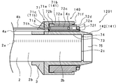
- FIG. 13 is a cross-sectional view showing a state in which the ligating device 1201 according to the thirteenth embodiment of the present invention is mounted on the endoscope 2, and shows a state where the sliding portion 72 is located on the base end side.
- FIG. 13 shows only the distal end of the endoscope 2 to which the ligating device 1201 is attached.
- the right side in the figure is the distal side (distal side) to be inserted into the body, and the left side is the proximal side (hand side, proximal side).
- the same members as those of the ligating device 601 of the seventh embodiment are given the same reference numerals, and detailed description is omitted.
- the ligating device 1201 includes the mounting tube 3, the main body 140, the first tube 4a, the second tube 4b, and the first ligating ring 5.
- the main body 140 has a cylindrical base portion 141 and a cylindrical sliding portion 72, is connected to the distal end of the mounting tube 3, and is located at the endoscope distal end portion 2b.
- the base portion 141 has a distal end portion 142 protruding more distally than the distal end surface 2c of the endoscope 2, and a base end portion 71b.
- the tip 142 has a tapered shape that tapers toward the tip.
- the first ligating ring 5 detached from the sliding portion 72 can be tapered without moving the sliding portion 72 toward the distal end from the distal end of the base portion 141.
- the distal end 142 having the shape the distal end can be moved to the distal end side while reducing the diameter along the distal end 142, and the affected part can be ligated.
- FIG. 14 is a cross-sectional view showing a state where the ligating device 1301 according to the fourteenth embodiment of the present invention is mounted on the endoscope 2, and shows a state where the sliding portion 132 is located on the proximal end side.
- FIG. 14 shows only the distal end of the endoscope 2 to which the ligation device 1301 is attached.
- the right side in the figure is the distal side (distal side) to be inserted into the body, and the left side is the proximal side (hand side, proximal side).
- the same members as those of the ligating device 1101 of the twelfth embodiment are denoted by the same reference numerals, and detailed description is omitted.
- the ligating device 1301 includes the mounting tube 3, the main body 150, the first tube 4a, the second tube 4b, the first ligating ring 5a, and the second ligating ring 5b.
- the main body 150 has a cylindrical base part 151 and a cylindrical sliding part 132, is connected to the tip of the mounting tube 3, and is located at the endoscope tip part 2b.
- the base 151 has a distal end 152 protruding distally from the distal end surface 2c of the endoscope 2, and a proximal end 71b.
- the tip 152 has a tapered shape that tapers toward the tip.
- the first ligating ring 5a and the second When the ligating ring 5b moves to the tapered distal end 152, it moves to the distal end side while reducing the diameter along the distal end 152, so that the affected part can be ligated.
- FIG. 15 is a partially cutaway sectional view of a ligating device 1401 including the endoscope unit 2 according to the fifteenth embodiment of the present invention.
- FIG. 15 shows only the distal end of the ligating device 1401 including the endoscope unit 2.
- the right side in the figure is the distal side (distal side) to be inserted into the body, and the left side is the proximal side (hand side, proximal side).
- the same members as those of the ligating device 1 of the first embodiment are denoted by the same reference numerals, and detailed description is omitted.
- the ligating device 1401 includes the main body 160, the endoscope unit 2, the tube 4, and the first ligating ring 5.
- the endoscope 2 has a forceps hole 2a through which a forceps (not shown) is inserted.
- the main body 160 has a cylindrical shape, is located at the endoscope distal end portion 2b of the endoscope section 2, and is provided integrally with the endoscope distal end portion 2b.
- the main body 160 has a distal end portion 161 that projects more distally than the distal end surface 2c of the endoscope section 2.
- the main body 160 has a first fluid supply passage 162 extending along the axial direction thereof.
- the first fluid supply path 162 has a first opening 164 that opens to the distal end surface 163 of the main body 160.
- the distal end 161 of the main body 160 has an annular convex portion 165 that is located on the inner peripheral side of the first opening 164 and protrudes toward the distal end.
- the distal end portion 161 and the distal end surface 2c of the endoscope 2 form a concave space 166.
- the material forming the main body 160 is the same as the material forming the main body 10 of the first embodiment, and thus the detailed description thereof will be omitted with reference to the description of the first embodiment.
- the tube 4 extends from the distal end to the proximal end along the endoscope unit 2.
- the distal end of the tube 4 is connected to the proximal end of the first fluid supply path 162 in an airtight state.
- the first ligating ring 5 is mounted on the outer periphery of the convex portion 165 of the distal end portion 161 of the main body 160 so as to close the first opening 164 in an airtight state.
- the first ligating ring 5 is attached to the distal end 161 of the main body 160 so as to close the first opening 164 in an airtight state.
- the first ligating ring 5 can be reliably removed from the main body 140 by using the pressure of the fluid flowing through the first fluid supply passage 162 as a drive source.
- the fluid for detaching the ligating rings 5, 5a, 5b and driving the sliding portions 72, 82, 92, 112, 122, 132 is air. It may be a liquid.
- the ligation device of the above embodiment one or two ligation rings are detached, but three or more ligation rings may be detachable.
- a ring-shaped member made of a shape memory alloy can be used as the ligating ring. Such a ring-shaped member changes its shape from a circular shape to a non-circular shape when detached from the main body of the ligating device, so that ligating can be performed according to the shape of the affected part.
- a clip formed of a shape memory alloy can be used as the ligating ring.
- a clip is ring-shaped when attached to the body of the ligating device, and deforms to a shape whose shape is stored in advance when detached from the body.
Landscapes
- Health & Medical Sciences (AREA)
- Surgery (AREA)
- Life Sciences & Earth Sciences (AREA)
- Heart & Thoracic Surgery (AREA)
- Molecular Biology (AREA)
- Vascular Medicine (AREA)
- Engineering & Computer Science (AREA)
- Biomedical Technology (AREA)
- Reproductive Health (AREA)
- Medical Informatics (AREA)
- Nuclear Medicine, Radiotherapy & Molecular Imaging (AREA)
- Animal Behavior & Ethology (AREA)
- General Health & Medical Sciences (AREA)
- Public Health (AREA)
- Veterinary Medicine (AREA)
- Surgical Instruments (AREA)
- Endoscopes (AREA)
Abstract
L'invention concerne un dispositif de ligature qui permet à un anneau de ligature d'être libéré de manière fiable à partir du corps principal de dispositif. Ce dispositif de ligature 1 est pourvu : d'un corps principal 10 cylindrique situé au niveau d'une partie d'extrémité distale d'endoscope 2b, ayant une partie d'extrémité distale 11 faisant saillie de manière distale au-delà de la face d'extrémité distale 2c de l'endoscope 2, et ayant un premier trajet d'alimentation en fluide 12 formé à l'intérieur de celui-ci, le premier trajet d'alimentation en fluide 12 ayant une première ouverture 14 ouverte au niveau de la face d'extrémité distale 13 de la partie d'extrémité distale 11; et d'un premier anneau de ligature 5 monté sur la partie d'extrémité distale 11 du corps principal 10 pour sceller la première ouverture 14.
Priority Applications (5)
| Application Number | Priority Date | Filing Date | Title |
|---|---|---|---|
| PCT/JP2018/026228 WO2020012585A1 (fr) | 2018-07-11 | 2018-07-11 | Dispositif de ligature |
| EP18925787.6A EP3821823A4 (fr) | 2018-07-11 | 2018-07-11 | Dispositif de ligature |
| CN201880095493.8A CN112384151A (zh) | 2018-07-11 | 2018-07-11 | 结扎用器件 |
| JP2020529902A JP7118150B2 (ja) | 2018-07-11 | 2018-07-11 | 結紮用デバイス |
| US17/144,468 US20210128157A1 (en) | 2018-07-11 | 2021-01-08 | Ligation device |
Applications Claiming Priority (1)
| Application Number | Priority Date | Filing Date | Title |
|---|---|---|---|
| PCT/JP2018/026228 WO2020012585A1 (fr) | 2018-07-11 | 2018-07-11 | Dispositif de ligature |
Related Child Applications (1)
| Application Number | Title | Priority Date | Filing Date |
|---|---|---|---|
| US17/144,468 Continuation US20210128157A1 (en) | 2018-07-11 | 2021-01-08 | Ligation device |
Publications (1)
| Publication Number | Publication Date |
|---|---|
| WO2020012585A1 true WO2020012585A1 (fr) | 2020-01-16 |
Family
ID=69142348
Family Applications (1)
| Application Number | Title | Priority Date | Filing Date |
|---|---|---|---|
| PCT/JP2018/026228 Ceased WO2020012585A1 (fr) | 2018-07-11 | 2018-07-11 | Dispositif de ligature |
Country Status (5)
| Country | Link |
|---|---|
| US (1) | US20210128157A1 (fr) |
| EP (1) | EP3821823A4 (fr) |
| JP (1) | JP7118150B2 (fr) |
| CN (1) | CN112384151A (fr) |
| WO (1) | WO2020012585A1 (fr) |
Families Citing this family (2)
| Publication number | Priority date | Publication date | Assignee | Title |
|---|---|---|---|---|
| US12127742B2 (en) * | 2019-07-26 | 2024-10-29 | Boston Scientific Scimed, Inc. | Devices, systems, and methods for closing a wound |
| US12114860B2 (en) | 2019-11-27 | 2024-10-15 | Boston Scientific Scimed, Inc. | Devices, systems, and methods for securing tissue |
Citations (5)
| Publication number | Priority date | Publication date | Assignee | Title |
|---|---|---|---|---|
| JPH0759786A (ja) | 1993-08-20 | 1995-03-07 | Sumitomo Bakelite Co Ltd | 内視鏡的結紮用キット |
| JP2001170061A (ja) * | 1999-12-17 | 2001-06-26 | Sumitomo Bakelite Co Ltd | 連発式結紮用キットの先端デバイス |
| JP2001353161A (ja) * | 2000-04-19 | 2001-12-25 | Ensurg Inc | 可動結紮バンドディスペンサ |
| JP2004081376A (ja) * | 2002-08-26 | 2004-03-18 | Top:Kk | 結紮治療具 |
| JP2009183460A (ja) * | 2008-02-06 | 2009-08-20 | Sumitomo Bakelite Co Ltd | 痔核結紮具およびこれを含む結紮用キット |
Family Cites Families (4)
| Publication number | Priority date | Publication date | Assignee | Title |
|---|---|---|---|---|
| JP3650149B2 (ja) * | 1994-08-11 | 2005-05-18 | 住友ベークライト株式会社 | 内視鏡結紮用具 |
| JP3514410B2 (ja) * | 1996-12-27 | 2004-03-31 | 住友ベークライト株式会社 | 内視鏡的結紮用キット |
| ID24763A (id) * | 1998-08-20 | 2000-08-03 | Sumitomo Bakelite Co | Perkakas ligasi berurutan |
| JP2002282260A (ja) * | 2001-03-27 | 2002-10-02 | Sumitomo Bakelite Co Ltd | 連発式結紮用デバイス |
-
2018
- 2018-07-11 WO PCT/JP2018/026228 patent/WO2020012585A1/fr not_active Ceased
- 2018-07-11 JP JP2020529902A patent/JP7118150B2/ja active Active
- 2018-07-11 EP EP18925787.6A patent/EP3821823A4/fr not_active Withdrawn
- 2018-07-11 CN CN201880095493.8A patent/CN112384151A/zh not_active Withdrawn
-
2021
- 2021-01-08 US US17/144,468 patent/US20210128157A1/en not_active Abandoned
Patent Citations (5)
| Publication number | Priority date | Publication date | Assignee | Title |
|---|---|---|---|---|
| JPH0759786A (ja) | 1993-08-20 | 1995-03-07 | Sumitomo Bakelite Co Ltd | 内視鏡的結紮用キット |
| JP2001170061A (ja) * | 1999-12-17 | 2001-06-26 | Sumitomo Bakelite Co Ltd | 連発式結紮用キットの先端デバイス |
| JP2001353161A (ja) * | 2000-04-19 | 2001-12-25 | Ensurg Inc | 可動結紮バンドディスペンサ |
| JP2004081376A (ja) * | 2002-08-26 | 2004-03-18 | Top:Kk | 結紮治療具 |
| JP2009183460A (ja) * | 2008-02-06 | 2009-08-20 | Sumitomo Bakelite Co Ltd | 痔核結紮具およびこれを含む結紮用キット |
Non-Patent Citations (1)
| Title |
|---|
| See also references of EP3821823A4 |
Also Published As
| Publication number | Publication date |
|---|---|
| US20210128157A1 (en) | 2021-05-06 |
| EP3821823A1 (fr) | 2021-05-19 |
| JPWO2020012585A1 (ja) | 2021-07-15 |
| EP3821823A4 (fr) | 2022-02-23 |
| JP7118150B2 (ja) | 2022-08-15 |
| CN112384151A (zh) | 2021-02-19 |
Similar Documents
| Publication | Publication Date | Title |
|---|---|---|
| JP7436447B2 (ja) | 内視鏡用の使い捨ての吸引バルブ | |
| EP3975818B1 (fr) | Valve médicale | |
| JP4667038B2 (ja) | 内視鏡付属品装着アダプタ | |
| US7150752B2 (en) | Endoscopic instrument | |
| JP3911068B2 (ja) | 外科器械用の関節運動伝達機構 | |
| EP1535565A1 (fr) | Dispositif d'insertion pour un endoscope | |
| US20060004406A1 (en) | Surgical instrument | |
| JPH10108868A (ja) | 弁および弁付トラカール外套管 | |
| JP6926077B2 (ja) | 外科用エンドエフェクタ装填デバイス及びトロカール一体化 | |
| JP2003275172A (ja) | 内視鏡用吸引バルブ | |
| JP7118150B2 (ja) | 結紮用デバイス | |
| US6923756B2 (en) | Multifunctional medical tool | |
| AU2017397500A1 (en) | Surgical clip applier with user feedback feature | |
| JP2015000344A (ja) | Eeaアンビルスナップリング作動器 | |
| CN117158875A (zh) | 一种内窥镜器械管、远端可扩张插入部和内窥镜 | |
| JP7118151B2 (ja) | 結紮用デバイス | |
| WO2022038783A1 (fr) | Dispositif de ligature | |
| JP4133969B2 (ja) | クリップおよびクリップ装置 | |
| US10149696B2 (en) | Medical instrument | |
| CN119606281A (zh) | 一种内窥镜及其吸引阀 | |
| JP2023147689A (ja) | 結紮用デバイス | |
| JP2025083867A (ja) | 結紮用デバイス | |
| US20260054049A1 (en) | Hemostasis valve | |
| US20220265375A1 (en) | Instrument for a robotic surgery system | |
| JP2006296609A (ja) | 内視鏡の鉗子栓 |
Legal Events
| Date | Code | Title | Description |
|---|---|---|---|
| 121 | Ep: the epo has been informed by wipo that ep was designated in this application |
Ref document number: 18925787 Country of ref document: EP Kind code of ref document: A1 |
|
| ENP | Entry into the national phase |
Ref document number: 2020529902 Country of ref document: JP Kind code of ref document: A |
|
| NENP | Non-entry into the national phase |
Ref country code: DE |