WO2020012640A1 - 熱転写プリンタおよび印画方法 - Google Patents
熱転写プリンタおよび印画方法 Download PDFInfo
- Publication number
- WO2020012640A1 WO2020012640A1 PCT/JP2018/026497 JP2018026497W WO2020012640A1 WO 2020012640 A1 WO2020012640 A1 WO 2020012640A1 JP 2018026497 W JP2018026497 W JP 2018026497W WO 2020012640 A1 WO2020012640 A1 WO 2020012640A1
- Authority
- WO
- WIPO (PCT)
- Prior art keywords
- image
- unit
- gbe
- gae
- superimposed
- Prior art date
- Legal status (The legal status is an assumption and is not a legal conclusion. Google has not performed a legal analysis and makes no representation as to the accuracy of the status listed.)
- Ceased
Links
Images






Classifications
-
- B—PERFORMING OPERATIONS; TRANSPORTING
- B41—PRINTING; LINING MACHINES; TYPEWRITERS; STAMPS
- B41J—TYPEWRITERS; SELECTIVE PRINTING MECHANISMS, i.e. MECHANISMS PRINTING OTHERWISE THAN FROM A FORME; CORRECTION OF TYPOGRAPHICAL ERRORS
- B41J2/00—Typewriters or selective printing mechanisms characterised by the printing or marking process for which they are designed
- B41J2/315—Typewriters or selective printing mechanisms characterised by the printing or marking process for which they are designed characterised by selective application of heat to a heat sensitive printing or impression-transfer material
- B41J2/32—Typewriters or selective printing mechanisms characterised by the printing or marking process for which they are designed characterised by selective application of heat to a heat sensitive printing or impression-transfer material using thermal heads
- B41J2/325—Typewriters or selective printing mechanisms characterised by the printing or marking process for which they are designed characterised by selective application of heat to a heat sensitive printing or impression-transfer material using thermal heads by selective transfer of ink from ink carrier, e.g. from ink ribbon or sheet
-
- B—PERFORMING OPERATIONS; TRANSPORTING
- B41—PRINTING; LINING MACHINES; TYPEWRITERS; STAMPS
- B41J—TYPEWRITERS; SELECTIVE PRINTING MECHANISMS, i.e. MECHANISMS PRINTING OTHERWISE THAN FROM A FORME; CORRECTION OF TYPOGRAPHICAL ERRORS
- B41J17/00—Mechanisms for manipulating page-width impression-transfer material, e.g. carbon paper
- B41J17/02—Feeding mechanisms
- B41J17/08—Feed independent of the record-paper feed
-
- B—PERFORMING OPERATIONS; TRANSPORTING
- B41—PRINTING; LINING MACHINES; TYPEWRITERS; STAMPS
- B41J—TYPEWRITERS; SELECTIVE PRINTING MECHANISMS, i.e. MECHANISMS PRINTING OTHERWISE THAN FROM A FORME; CORRECTION OF TYPOGRAPHICAL ERRORS
- B41J2/00—Typewriters or selective printing mechanisms characterised by the printing or marking process for which they are designed
- B41J2/005—Typewriters or selective printing mechanisms characterised by the printing or marking process for which they are designed characterised by bringing liquid or particles selectively into contact with a printing material
- B41J2/01—Ink jet
- B41J2/205—Ink jet for printing a discrete number of tones
- B41J2/2056—Ink jet for printing a discrete number of tones by ink density change
-
- B—PERFORMING OPERATIONS; TRANSPORTING
- B41—PRINTING; LINING MACHINES; TYPEWRITERS; STAMPS
- B41J—TYPEWRITERS; SELECTIVE PRINTING MECHANISMS, i.e. MECHANISMS PRINTING OTHERWISE THAN FROM A FORME; CORRECTION OF TYPOGRAPHICAL ERRORS
- B41J2/00—Typewriters or selective printing mechanisms characterised by the printing or marking process for which they are designed
- B41J2/315—Typewriters or selective printing mechanisms characterised by the printing or marking process for which they are designed characterised by selective application of heat to a heat sensitive printing or impression-transfer material
- B41J2/32—Typewriters or selective printing mechanisms characterised by the printing or marking process for which they are designed characterised by selective application of heat to a heat sensitive printing or impression-transfer material using thermal heads
- B41J2/35—Typewriters or selective printing mechanisms characterised by the printing or marking process for which they are designed characterised by selective application of heat to a heat sensitive printing or impression-transfer material using thermal heads providing current or voltage to the thermal head
- B41J2/355—Control circuits for heating-element selection
- B41J2/36—Print density control
-
- B—PERFORMING OPERATIONS; TRANSPORTING
- B41—PRINTING; LINING MACHINES; TYPEWRITERS; STAMPS
- B41J—TYPEWRITERS; SELECTIVE PRINTING MECHANISMS, i.e. MECHANISMS PRINTING OTHERWISE THAN FROM A FORME; CORRECTION OF TYPOGRAPHICAL ERRORS
- B41J2/00—Typewriters or selective printing mechanisms characterised by the printing or marking process for which they are designed
- B41J2/005—Typewriters or selective printing mechanisms characterised by the printing or marking process for which they are designed characterised by bringing liquid or particles selectively into contact with a printing material
- B41J2/01—Ink jet
- B41J2/205—Ink jet for printing a discrete number of tones
- B41J2/2052—Ink jet for printing a discrete number of tones by dot superpositioning, e.g. multipass doubling
-
- B—PERFORMING OPERATIONS; TRANSPORTING
- B41—PRINTING; LINING MACHINES; TYPEWRITERS; STAMPS
- B41J—TYPEWRITERS; SELECTIVE PRINTING MECHANISMS, i.e. MECHANISMS PRINTING OTHERWISE THAN FROM A FORME; CORRECTION OF TYPOGRAPHICAL ERRORS
- B41J2/00—Typewriters or selective printing mechanisms characterised by the printing or marking process for which they are designed
- B41J2/315—Typewriters or selective printing mechanisms characterised by the printing or marking process for which they are designed characterised by selective application of heat to a heat sensitive printing or impression-transfer material
- B41J2/32—Typewriters or selective printing mechanisms characterised by the printing or marking process for which they are designed characterised by selective application of heat to a heat sensitive printing or impression-transfer material using thermal heads
- B41J2/35—Typewriters or selective printing mechanisms characterised by the printing or marking process for which they are designed characterised by selective application of heat to a heat sensitive printing or impression-transfer material using thermal heads providing current or voltage to the thermal head
- B41J2/355—Control circuits for heating-element selection
- B41J2/36—Print density control
- B41J2/362—Correcting density variation
Definitions
- the present invention relates to a thermal transfer printer and a printing method having a function of printing a long image using two or more images.
- a thermal head heats an ink sheet to perform an image printing process for printing an image on paper.
- yellow, magenta and cyan are also referred to as “Y”, “M” and “C”, respectively.
- Y, M, and C inks are applied to the ink sheet.
- the Y component image is also referred to as a “Y image”.
- the image of the M component is also referred to as “M image”.
- the C component image is also referred to as “C image”.
- an area on a sheet for printing an image is also referred to as a “print area”.
- the thermal transfer printer transfers the Y image, the M image, and the C image to the printing area of the sheet in the order of the Y image, the M image, and the C image. As a result, a color image is printed on the printing area of the sheet.
- a digital camera or a portable terminal provided with a camera is generally provided with a panorama shooting mode for performing panorama shooting.
- the mobile terminal is a mobile phone, a smartphone, or the like. Therefore, there is an increasing demand for performing panoramic printing for printing a long panoramic image obtained by panoramic shooting.
- the size of a panoramic image in the sub-scanning direction is also referred to as “panorama size”.
- an area of the ink sheet used in one printing process is also referred to as an “area Rt1”.
- the size of the region Rt1 is a normal print size (for example, L size).
- the panorama size is larger than the size of the region Rt1 in the sub-scanning direction.
- the upper limit of the image size that can be printed by the thermal transfer printer in one printing process is the size of the region Rt1. Therefore, in a thermal transfer printer, a special ink sheet is required to print a panoramic image in one printing process.
- panoramic printing in order to perform panoramic printing, first, for example, two images are acquired from a panoramic image. Then, by sequentially printing the two images on a sheet so that the two images are connected, panoramic printing is realized.
- the panoramic printing for example, two types of regions Rt1 for printing two images in the ink sheet are used.
- Patent Documents 1 and 2 disclose a technique for printing a panoramic image by superposing the leading end of the second image on the trailing end of the first image.
- Patent Literature 1 in a region where the leading edge of the second image overlaps the trailing edge of the first image, the boundary between the two images is made inconspicuous (hereinafter, referred to as “ Related configuration A ”) is disclosed.
- the density of the rear end of the first image gradually decreases from the front end to the rear end of the rear end. Further, the density of the front end of the second image gradually increases from the front end to the rear end of the front end. As a result, the print density in the overlapping area is adjusted. Printing is an image printed on paper.
- Patent Document 2 discloses another configuration (hereinafter, also referred to as “related configuration B”) that makes the boundary between two images inconspicuous. Specifically, in the related configuration B, the superimposed portion of the two images is shifted in the sub-scanning transfer direction for each of the Y, M, and C colors. Further, the gradation data of the overlapping portion is corrected for each line in the sub-scanning transfer direction based on a preset correction coefficient.
- a situation may occur in which the leading end of the second image is shifted and overlaps the trailing end of the first image. .
- the image quality of an area where the front end overlaps the rear end (hereinafter, also referred to as an “overlapping area”) changes.
- the superimposition area is an area included in the panoramic image.
- the present invention has been made to solve such a problem, and suppresses a change in image quality of a panoramic image that occurs in a situation where the leading end of the second image is shifted and overlaps the trailing end of the first image. It is an object of the present invention to provide a thermal transfer printer or the like capable of performing the above.
- a thermal transfer printer uses an ink sheet to print a panoramic image represented by a plurality of images including a first image and a second image on paper. Perform processing.
- the first image has a first superimposed portion that is a rear end of the first image
- the second image has a second superimposed portion that is a front end of the second image
- the panoramic image Is represented by at least the first image and the second image in a situation where the second superimposition section is superimposed on the first superimposition section
- the thermal transfer printer includes the first superimposition section and the second superimposition section.
- a filter processing unit that performs a filtering process; and a density process that adjusts the density of the first superimposing unit that has performed the filtering process and the density of the second superimposing unit that has performed the filtering process.
- the density adjusting unit that performs the superimposing unit and the second superimposing unit and the second superimposing unit that performs the density processing are superimposed on the first superimposing unit that has performed the density processing, at least the The first image and the second image A printing unit for performing the printing process of printing the expressed panoramic image on the paper, wherein the panoramic image has a superimposed area, and the superimposed area is provided on the first superimposing unit by the second superimposing unit.
- the first image has a first superimposed portion that is a rear end of the first image.
- the second image has a second superimposed portion that is a tip of the second image.
- the filter processing unit performs a filtering process on the first superimposing unit and the second superimposing unit.
- the panoramic image has a superimposed area.
- the filtering process is a process of reducing a change in image quality of the superimposed region, which occurs in a situation where the second superimposed portion is shifted and overlaps the first superimposed portion.
- FIG. 2 is a block diagram illustrating a main configuration of the thermal transfer printer according to the first embodiment.
- FIG. 2 is a diagram illustrating a configuration of a printing unit according to the first embodiment.
- FIG. 3 is a diagram for explaining an ink sheet. It is a figure for explaining a panorama image.
- 5 is a flowchart of a print control process according to the first embodiment.
- FIG. 4 is a diagram illustrating an image for explaining a print control process. It is a figure showing an image for explaining filter processing. It is a figure showing the state of the gradation of the superimposition area.
- FIG. 9 is a block diagram illustrating a main configuration of a thermal transfer printer according to a second embodiment. 9 is a flowchart of a print control process A according to the second embodiment.
- FIG. 2 is a block diagram illustrating a characteristic functional configuration of the thermal transfer printer.
- FIG. 2 is a hardware configuration diagram of the thermal transfer printer.
- FIG. 9 is a diagram for explaining processing in a comparative example.
- FIG. 10 is a diagram illustrating a state of a gray scale in a superimposed region in a comparative example.
- FIG. 1 is a block diagram illustrating a main configuration of the thermal transfer printer 100 according to the first embodiment.
- FIG. 1 does not show components (for example, a power supply) that are not related to the first embodiment.
- FIG. 1 also shows an information processing apparatus 200 that is not included in the thermal transfer printer 100 for explanation.
- the thermal transfer printer 100 is, for example, a thermal transfer printer. Although described in detail later, the thermal transfer printer 100 performs a printing process P for printing an image on paper.
- the information processing device 200 is a device that controls the thermal transfer printer 100.
- the information processing device 200 is, for example, a PC (Personal Computer).
- the information processing device 200 is operated by a user. When the user performs a printing execution operation on the information processing apparatus 200, the information processing apparatus 200 transmits a printing instruction and image data D1 to the thermal transfer printer 100.
- the printing execution operation is an operation for causing the thermal transfer printer 100 to execute the printing process P.
- the print instruction is an instruction for causing the thermal transfer printer 100 to execute the print processing P.
- the image data D1 is data of an image to be printed on a sheet.
- the image indicated by the image data D1 includes a Y image, an M image, and a C image.
- the thermal transfer printer 100 includes a storage unit 10, a control unit 20, a printing unit 30, and a communication unit 40.
- the communication unit 40 has a function of communicating with the information processing device 200.
- the communication unit 40 performs communication using, for example, a USB (Universal Serial Bus) interface.
- the print instruction and the image data D1 transmitted by the information processing device 200 are transmitted to the control unit 20 via the communication unit 40.
- the storage unit 10 is a memory that stores various data, programs, and the like.
- the storage unit 10 includes, for example, a volatile memory and a nonvolatile memory.
- a volatile memory is a memory that temporarily stores data.
- the volatile memory is, for example, a RAM (Random Access Memory).
- the image data D1 is stored in a volatile memory.
- the nonvolatile memory stores a control program, initial setting values, and the like.
- the nonvolatile memory is, for example, a flash memory.
- the control unit 20 operates according to the control program stored in the storage unit 10.
- the control unit 20 performs various processes on each unit of the thermal transfer printer 100, which will be described later in detail.
- the control unit 20 is, for example, a processor such as a CPU (Central Processing Unit).
- the control unit 20 includes a print control unit 21, an image processing unit 22, a filter processing unit 23, and a density adjustment unit 24. All or a part of the print control unit 21, the image processing unit 22, the filter processing unit 23, and the density adjustment unit 24 are, for example, program modules executed by the control unit 20. In other words, all or a part of the print control unit 21, the image processing unit 22, the filter processing unit 23, and the density adjustment unit 24 are realized by the control unit 20 performing various processes according to a program stored in a memory or the like. Is done.
- all or a part of the print control unit 21, the image processing unit 22, the filter processing unit 23, and the density adjustment unit 24 may be configured by a signal processing circuit configured by a hardware electric circuit.
- the print control unit 21 has a function of controlling the printing unit 30, as will be described later in detail. The processing performed by each of the image processing unit 22, the filter processing unit 23, and the density adjustment unit 24 will be described later.
- FIG. 2 is a diagram illustrating a configuration of the printing unit 30 according to the first embodiment.
- FIG. 2 shows the configuration of the printing unit 30 in a state where the roll paper 2r and the ink sheet 6 are mounted on the thermal transfer printer 100 (printing unit 30).
- the roll paper 2r is configured by winding a long paper 2 in a roll shape.
- the motor Mt2 is a motor for rotating the roll paper 2r.
- the print control unit 21 controls the motor Mt2.
- the motor Mt2 rotates the roll paper 2r so that the paper 2 is supplied or the paper 2 is wound.
- the ink sheet 6 is a long sheet.
- the ink sheet 6 is made of a material having heat resistance.
- the ink sheet 6 is made of, for example, a plastic film.
- FIG. 3 is a diagram for explaining the ink sheet 6.
- the X direction and the Y direction are orthogonal to each other.
- the X direction and the Y direction shown in the following figures are also orthogonal to each other.
- a direction including the X direction and a direction opposite to the X direction ( ⁇ X direction) is also referred to as “X-axis direction”.
- a direction including the Y direction and a direction opposite to the Y direction ( ⁇ Y direction) is also referred to as a “Y-axis direction”.
- a plane including the X-axis direction and the Y-axis direction is also referred to as “XY plane”.
- the ⁇ X direction is a direction toward an ink roll 6 rm described later.
- the X direction is a direction toward an ink roll 6r described later. A detailed description of the ink sheet 6 will be described later.
- the printing unit 30 includes the thermal head 7, the transport roller pair 3, the platen roller 4, the bobbins 9a and 9b, the motors Mt2, Mt3, Mt6a, Mt6b, and the cutter Ct1. Prepare.
- the thermal head 7 has a function of emitting heat.
- the transport roller pair 3 is a roller pair for transporting the paper 2.
- the transport roller pair 3 includes a grip roller 3a and a pinch roller 3b.
- the motor Mt3 is a motor for rotating the grip roller 3a.
- the print control unit 21 controls the motor Mt3 so that the sheet 2 is conveyed.
- One end of the ink sheet 6 is attached to the bobbin 9a.
- the other end of the ink sheet 6 is attached to the bobbin 9b.
- An ink roll 6r is formed by winding one end of the ink sheet 6 around the bobbin 9a.
- the other end of the ink sheet 6 is wound around the bobbin 9b to form an ink roll 6rm.
- the ink roll 6r is a roll that supplies the ink sheet 6.
- the ink roll 6 rm is a roll for winding the ink sheet 6.
- the motor Mt6a is a motor for rotating the bobbin 9a (ink roll 6r).
- the motor Mt6b is a motor for rotating the bobbin 9b (ink roll 6rm).
- the print control unit 21 controls the motors Mt6a and Mt6b so that the ink sheet 6 is conveyed.
- the bobbin 9b rotates so as to wind up the ink sheet 6. That is, with the rotation of the bobbin 9b, the ink roll 6rm rotates so as to wind up the ink sheet 6.
- the ink roll 6r (bobbin 9a) also rotates with the rotation of the ink roll 6rm. Therefore, the ink roll 6r supplies the ink sheet 6 by the length of the wound ink sheet 6 as the ink roll 6rm winds a part of the ink sheet 6.
- the motor Mt6a rotates the bobbin 9a and the motor Mt6b rotates the bobbin 9b so that a prescribed tension is generated in the ink sheet 6.
- the platen roller 4 is provided so as to face a part of the thermal head 7.
- the platen roller 4 is configured to be movable so that the ink sheet 6 and the paper 2 can be sandwiched by the platen roller 4 and the thermal head 7.
- the platen roller 4 contacts the thermal head 7 via the paper 2 and the ink sheet 6.
- the platen contact state is a state in which the sheet 2 and the ink sheet 6 are sandwiched between the platen roller 4 and the thermal head 7.
- the thermal head 7 heats the ink sheet 6, so that the dye (ink) of the ink sheet 6 is transferred to the paper 2.
- the cutter Ct1 has a function of cutting a part of the sheet 2.
- ink region R10 is periodically arranged in ink sheet 6 along the longitudinal direction (X-axis direction) of ink sheet 6.
- ⁇ Dyes 6y, 6m, 6c and a protective material 6op are provided in the ink region R10.
- Each of the dyes 6y, 6m, 6c and the protective material 6op is a transfer material that is transferred to the paper 2 by being heated by the thermal head 7.
- Each of the dyes 6y, 6m, and 6c indicates a color to be transferred to the paper 2.
- the dyes 6y, 6m, and 6c exhibit yellow, magenta, and cyan colors, respectively.
- each of the Y dye, the M dye, and the C dye is also referred to as a “color dye”.
- an area for printing an image on the sheet 2 is also referred to as a “print area”.
- a unit printing process is performed.
- the ink sheet 6 and the paper 2 are simultaneously conveyed while the thermal head 7 heats the transfer material of the ink sheet 6 in the platen contact state. As a result, the transfer material is transferred to the printing area of the sheet 2 for each line.
- the unit printing process described above is repeatedly performed on each of the dyes 6y, 6m, 6c and the protection material 6op as transfer materials, so that the dyes 6y, 6m, 6c and the protection material 6op are printed on the printing area of the paper 2. Is transferred in the order of the dyes 6y, 6m, 6c and the protective material 6op. As a result, an image is printed on the printing area of the sheet 2, and the image is protected by the protective layer made of the protective material 6op.
- the protection material 6op is made of, for example, a material that reduces the influence of ultraviolet rays.
- an image in which an image is printed in the printing area of the paper 2 is also referred to as a “printed matter”.
- the print is a part of the sheet 2.
- the cutter Ct1 cuts the paper 2 so that the print is separated from the paper 2. Thus, the print is discharged from the thermal transfer printer 100.
- the image printed on the printing area of the sheet 2 is also referred to as “image Gn”.
- the direction in which the paper 2 is transported is also referred to as “paper transport direction”.
- the sheet conveyance direction is the X-axis direction including the X direction and the ⁇ X direction.
- the thermal transfer printer 100 prints an image on the sheet 2.
- the sub-scanning direction is the paper transport direction.
- the main scanning direction is a direction orthogonal to the sub-scanning direction.
- the sheet transport direction is also referred to as “direction Drp”.
- region Rt1 the region of the ink sheet 6 where the dyes 6y, 6m, 6c and the protective material 6op are provided is also referred to as “region Rt1” or “Rt1” (see FIG. 3).
- the size of the region Rt1 corresponds to the size of one screen corresponding to the image Gn.
- the size of the region Rt1 is also referred to as “one screen size”.
- the length of the region Rt1 in the sub-scanning direction (X-axis direction) is also referred to as “length Lx” or “Lx”.
- the length Lx is predetermined. Therefore, when the ink sheet 6 is used, the upper limit of the length of the image Gn in the sub-scanning direction is the length Lx.
- the two adjacent ink regions R10 included in the ink sheet 6 are also referred to as an ink region R10a and an ink region R10b, respectively.
- the region Rt1 included in the ink region R10a is also referred to as “region Rt1a”.
- region Rt1 included in the ink region R10b is also referred to as “region Rt1b”.
- FIG. 4 is a diagram for explaining the panoramic image Gw.
- the main scanning direction is the Y axis direction
- the sub scanning direction is the X axis direction.
- the panoramic image Gw includes images Gwa and Gwb.
- the panoramic image Gw of the present embodiment is an image represented by the image Gwa and the image Gwb, which will be described later in detail.
- the images Gwa and Gwb are printed on the sheet 2 in the order of the images Gwa and Gwb.
- the thermal transfer printer 100 performs a printing process P for printing the panoramic image Gw on the paper 2 using the ink sheet 6.
- FIG. 4A is a diagram illustrating an example of the panoramic image Gw.
- the panoramic image Gw is composed of a plurality of pixels. Each pixel is represented by a tone value (pixel value) indicating the density.
- FIG. 4B shows an example of the image Gwa.
- the image Gwa has a superimposed portion Gae.
- the superimposed portion Gae is a rear end of the image Gwa.
- the overlapping portion Gae has a front end Gae1 and a rear end Gae2.
- the rear end Gae2 is the rear end of the image Gwa.
- FIG. 4C shows an example of the image Gwb.
- the image Gwb has a superimposed portion Gbe.
- the superimposition part Gbe is a tip part of the image Gwb.
- the overlapping portion Gbe has a front end Gbe1 and a rear end Gbe2.
- the tip Gbe1 is the tip of the image Gwb.
- the superimposed portion Gae of the image Gwa and the superimposed portion Gbe of the image Gwb are the same image.
- the panoramic image Gw has a superimposition region Rw.
- the superimposition region Rw is an area for superimposing the superimposition portion Gbe of the image Gwb on the superimposition portion Gae of the image Gwa.
- the shape of the superimposition region Rw is a rectangle.
- the overlapping region Rw has a front end Re1 and a rear end Re2.
- the tip Gae1 of the overlapping portion Gae corresponds to the tip Re1 of the overlapping region Rw.
- the rear end Gbe2 of the superimposed portion Gbe corresponds to the rear end Re2 of the superimposed region Rw.
- an image to be printed on the paper 2 is also referred to as a “target image”.
- Each of the images Gwa and Gwb is a target image.
- the state of the target image in a state where the target image is printed on the paper 2 is also referred to as a “print state”.
- the superimposed portion Gae (rear end) of the printed image Gwa and the superimposed portion Gbe (front end) of the printed image Gwb are images of the superimposed region Rw.
- the image Gwa is an image printed by the n-th printing process P.
- “N” is a natural number of 1 or more.
- the image Gwb is an image printed by the (n + 1) -th printing process P.
- the n-th printing process P and the (n + 1) -th printing process P are performed in order so that the overlapping portion Gbe overlaps the overlapping portion Gae.
- a density step may occur in the superimposed region Rw due to the characteristics of the thermal transfer printer. That is, when the overlapping portion Gbe is simply overlapped with the overlapping portion Gae, a density change occurs in the overlapping region Rw.
- image processing is performed to make the density step (density change) inconspicuous.
- the density processing for reducing the density change of the superimposition region Rw that occurs when the superimposition portion Gbe is superimposed on the superimposition portion Gae is performed by the superimposition portion Gae and the superimposition portion. Gbe is performed.
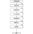
- FIG. 5 is a flowchart of the print control process according to the first embodiment.
- the information processing apparatus 200 transmits the printing instruction and the image data D1 indicating the panoramic image Gw in FIG. 6A to the thermal transfer printer 100.
- the panoramic image Gw in FIG. 6A includes an image Gwa and an image Gwb.
- the state of the panoramic image Gw transmitted from the information processing apparatus 200 to the thermal transfer printer 100 is also referred to as “original state”.
- the panoramic image Gw transmitted to the thermal transfer printer 100 is the original panoramic image Gw.
- the communication unit 40 of the thermal transfer printer 100 receives the original panoramic image Gw, and transmits the panoramic image Gw to the control unit 20.
- control unit 20 receives panoramic image Gw (step S110).
- the control unit 20 causes the storage unit 10 to store the received panoramic image Gw.
- the image processing unit 22 enlarges or reduces the panoramic image Gw so that the size of the panoramic image Gw becomes a specified size.
- an image that can be generated by one printing process P is also referred to as a “unit image”.
- the unit image is an image that can be generated using one ink region R10.
- step S120 an image acquisition process is performed.
- the image processing unit 22 acquires an image Gwa and an image Gwb as unit images from the original panoramic image Gw in FIG.
- the size of each of the images Gwa and Gwb is one screen size (the size of the region Rt1). Note that the size of each of the images Gwa and Gwb is not limited to one screen size. The size of each of the images Gwa and Gwb may be, for example, the minimum size that the thermal transfer printer 100 can print.
- a filtering process Fw is performed.
- the filter processing unit 23 performs a filter process on the superimposed portion Gae as an image and the superimposed portion Gbe as an image (Step S130).
- Each of the filter process performed on the superimposed portion Gbe as an image and the filter process performed on the superimposed portion Gbe as the image is a blur process.
- the blurring process is a process for reducing the sharpness of an image.
- the blurring process is a well-known technique, and thus a detailed description is omitted.
- the blurring process is a process for reducing high-frequency components included in frequency components of an image.
- the blurring process is a process for removing high-frequency components in a spatial frequency spectrum of an image, which is obtained by performing a two-dimensional Fourier transform on the image, for example.
- the edge portion changes to a low density change portion.
- the low density change portion is an image in which the difference (change) in the density (tone value) of a plurality of adjacent pixels is small.
- the amount of reduction in the sharpness of an image caused by performing a blurring process on an image is also referred to as “bluriness”.
- the higher the degree of blur the lower the sharpness of the image subjected to the blur processing.
- the smaller the degree of blur the higher the sharpness of the image subjected to the blur processing.
- the degree of blur can be changed by changing the size of the range of the high-frequency component to be removed.
- the blurring process is not limited to the process using the frequency component.
- the blurring process may be, for example, a process of changing tone values of a plurality of pixels forming an image using a plurality of coefficients indicated by a filter matrix.
- the filter matrix is, for example, a matrix of 3 rows and 3 columns.
- the degree of blur can be changed by changing a plurality of coefficients included in the filter matrix.
- the states of the superimposed portions Gae and Gbe that have been subjected to the filter processing are also referred to as “filtered states”.
- step S140 a density adjustment process is performed.
- the density adjustment unit 24 performs a density process for adjusting the density of the superimposed portion Gae in the filtered state and the density of the superimposed portion Gbe in the filtered state for the superimposed portion Gae and the superimposed portion Gbe. Do it.
- the density adjustment unit 24 reduces the density change in the superimposed region Rw that occurs when the filtered superimposition unit Gbe overlaps the filtered superimposition unit Gbe.
- the density processing is performed on the superimposed portion Gae and the superimposed portion Gbe. That is, the density adjustment process is a process of correcting the superimposed portion Gae and the superimposed portion Gbe such that a decrease in image quality of the superimposed region Rw, which occurs when the superimposed portion Gbe is superimposed on the superimposed portion Gae, is suppressed. .
- the density adjustment process is a process performed in, for example, the related configuration B described above. Hereinafter, the density adjustment processing will be briefly described.
- an image whose density gradually changes in the sub-scanning direction is also referred to as a “gradation image”.
- the overlapping portion Gae in which the concentration of the overlapping portion Gae gradually decreases from the leading end Gae1 to the trailing end Gae2 of the overlapping portion Gae is also referred to as “overlapping portion Gar”.
- the superimposed portion Gar is a gradation image.
- the superimposed portion Gbe in which the concentration of the superimposed portion Gbe gradually increases from the front end Gbe1 to the rear end Gbe2 of the superimposed portion Gbe is also referred to as “superimposed portion Gbr”.
- the superimposed portion Gbr is a gradation image.
- the density adjustment unit 24 includes a plurality of density adjustment units included in the overlapped portion Gae such that the overlapped portion Gae in the filtered state in the image Gwa becomes an overlapped portion Gar (gradation image).
- a density process for correcting the pixel density (gradation value) is performed.
- the density adjustment unit 24 adjusts the densities (tone values) of a plurality of pixels included in the superimposed portion Gbe so that the superimposed portion Gbe in the filtered state in the image Gwb becomes the superimposed portion Gbr (gradation image). The density processing for correction is performed.
- the density is adjusted so that the color tone equivalent to the color tone of the superimposed region Rw included in the panoramic image Gw in the original state can be reproduced.
- the superimposed portion Gae and the superimposed portion Gbe are corrected by the adjustment processing.
- a superimposed portion Gae in FIG. 6B and a superimposed portion Gbe in FIG. 6C are obtained.
- the superimposed portion Gae in FIG. 6B and the superimposed portion Gbe in FIG. 6C show simple images in which the density of the entire superimposed region Rw in FIG.
- the superimposed portion Gae in FIG. 6B is a superimposed portion Gar (gradation image)
- the superimposed portion Gbe in FIG. 6C is a superimposed portion Gbr (gradation image).
- the states of the superimposed portions Gae and Gbe on which the density processing (density adjustment processing) has been performed are also referred to as “density adjustment states”.
- the state of the image Gwa having the superimposed portion Gae in the density adjusted state is also referred to as a “corrected state”.
- the state of the image Gwb having the superimposed portion Gbe in the density adjustment state is also referred to as a “corrected state”.
- the control unit 20 generates print data using the images Gwa and Gwb.
- the print data is control data for printing the images Gwa and Gwb on the sheet 2.
- the control data is data for controlling heating of the thermal head 7, controlling a driving mechanism (for example, a motor) of the printing unit 30, and the like.
- step S150 the printing unit 30 performs the printing process Pw according to the printing data.
- the printing process Pw the printing process P is performed k times. “K” is an integer of 1 or more.
- the printing process Pw is a process of printing at least the panoramic image Gw represented by the image Gwa and the image Gwb on the sheet 2 in a situation where the superimposed portion Gbe in the density adjusted state is superimposed on the superposed portion Gbe in the density adjusted state.
- the printing process P is performed twice.
- the printing area for printing the image Gwa on the paper 2 is also referred to as “printing area Ra”.
- the printing area for printing the image Gwb on the paper 2 is also referred to as “printing area Rb”.
- the printing is performed such that the first printing process P and the second printing process P are performed in the order of the first printing process P and the second printing process P.
- the control unit 21 controls the printing unit 30.
- the first printing process P is a process for printing the corrected image Gwa on the printing region Ra of the paper 2 using the ink region R10a (region Rt1a) of the ink sheet 6.
- the second printing process P is a process for printing the corrected image Gwb on the printing region Rb of the sheet 2 using the ink region R10b (region Rt1b).
- the print control unit 21 controls the printing unit 30 so that the operation of printing the image Gwb is performed in the second printing process P. Specifically, in the second printing process P, the printing operation of the corrected image Gwb is performed so as to overlap the superimposed portion Gbe of the corrected image Gwb on the superimposed portion Gbe of the corrected image Gwa. Next, the print control unit 21 controls the printing unit 30. Since the printing process P has been described above, the description is omitted.
- the panoramic image Gw is printed on the sheet 2 by performing the printing process Pw on the premise Pm1.
- the state where the panoramic image Gw is printed on the sheet 2 is also referred to as “superimposed printing state”.
- the panoramic image Gw in the superimposed printing state is represented by at least the image Gwa and the image Gwb in a state where the superimposed portion Gbe is superimposed on the superimposed portion Gae.
- the superimposed region Rw of the panoramic image Gw in the superimposed printing state is a region where the superimposed portion Gbe overlaps the superimposed portion Gae.
- step S160 a cutting process is performed.
- a portion of the sheet 2 on which the panoramic image Gw is printed is also referred to as a “print”.
- the cutter Ct1 cuts the sheet 2 so that the print is separated from the sheet 2. Then, the print is discharged from the thermal transfer printer 100. Then, the print control process ends.
- the print control process in the comparative example is also referred to as “print control process N”.
- the print control process N is different from the print control process of FIG. 5 in that the filter process (step S130) is not performed.
- Other processes of the print control process N are the same as the print control process of FIG.
- the position where the image is printed is also referred to as “print position”.
- the printing process Pw described above there is a possibility that the printing position of the target image (both or one of the images Gwa and Gwb) is shifted. That is, there is a possibility that a state in which the entire superimposed portion Gbe of the image Gwb does not overlap the entire superimposed portion Gae of the image Gwa.
- a state in which the entire superimposed portion Gbe does not overlap the entire superimposed portion Gbe is also referred to as a “shift state”.
- a state in which the entire superimposed portion Gbe overlaps the entire superimposed portion Gae in the superimposed printing state is also referred to as a “normal state”. That is, the superimposed printing state includes a normal state and a shift state.
- the shift state is a state in which, in the superimposed printing state, for example, the entire superimposed portion Gbe in FIG. 6C does not overlap the entire superimposed portion Gbe in FIG. That is, the shift state is a state in which a shift occurs in both or one of the printing positions of the images Gwa and Gwb.
- the normal state is a state in which, in the superimposed printing state, for example, the entire superimposed portion Gbe in FIG. 6C overlaps the entire superimposed portion Gae in FIG. That is, the normal state is a state in which the printing positions of the images Gwa and Gwb are not shifted.
- the following premise Pm2 is considered.
- the original panoramic image Gw to be processed is the panoramic image Gw in FIG.
- the panoramic image Gw in FIG. 13A includes a superimposition region Rw indicating one line X1.
- the printing positions of the images Gwa and Gwb are shifted. That is, in the premise Pm2, a shift state occurs.
- the image Gwa and the image Gwb are obtained from the panoramic image Gw in FIG.
- the superimposed portion Gae of the image Gwa indicates one line X1.
- the superimposed portion Gbe of the image Gwb indicates one line X1.
- the density processing in the premise Pm2 is performed on the superimposed portion Gae and the superimposed portion Gbe.
- the printing process Pw in the premise Pm2 is performed. Thereby, the images Gwa and Gwb in the printing state and the panoramic image Gw in the superimposed printing state are obtained.
- the image Gwa (superimposed portion Gae) in the printing state under the premise Pm2 is as shown in the image Gwa (superimposed portion Gae) in FIG. Note that the printing position of the image Gwa in FIG. 13B is shifted.
- the image Gwb (superimposed portion Gbe) in the printing state under the premise Pm2 is as shown in the image Gwb (superimposed portion Gbe) in FIG. Note that the printing position of the image Gwb in FIG. 13C is shifted. Further, the panoramic image Gw in the superimposed printing state on the premise Pm2 is as shown in FIG. 13D.
- the position of the line X1 indicated by the image Gwa (superimposed portion Gae) in the printing state in FIG. 13B exists at a position shifted from the position of the line X1 in FIG. 13A.
- the position of the line X1 indicated by the image Gwb (superimposed portion Gbe) in the printing state in FIG. 13C exists at a position shifted from the position of the line X1 in FIG.
- the panoramic image Gw in FIG. 13D is obtained by combining the image Gwa in FIG. 13B and the image G in FIG. 13C in a state where the superimposed portion Gbe in FIG. ) Image Gwb. Therefore, two lines X1 are shown in the superimposed region Rw of the panoramic image Gw in the superimposed print state in FIG.
- the image represented by the superimposed portion Gae and the superimposed portion Gbe in the shifted state is also referred to as “superimposed image Gwc”.
- the superimposed area Rw (image) of the panoramic image Gw in FIG. 13D is the superimposed image Gwc.
- the superimposition region Rw (superimposed image Gwc) in FIG. 13D is an image in which the superimposition portion Gbe in FIG. 13C is superimposed on the superimposition portion Gae in FIG.
- FIG. 14A is a diagram showing the state of the gradation of the line X1 along the arrow line L1a of FIG. 13B by a gradation line X1an.
- the vertical axis indicates the gradation value
- the horizontal axis indicates the position in the X-axis direction.
- FIG. 14B is a diagram showing the state of the gradation of the line X1 along the arrow line L1b in FIG. 13C by using a gradation line X1bn.
- FIG. 14C is a diagram showing the state of the gradation of the two lines X1 along the arrow line L1c in FIG. 13D by the gradation line X1cn.
- the gradation line X1cn indicates two peaks.
- one line X1 indicated by the original panoramic image Gw is changed to the one shown in FIG. It is represented as two lines X1 as in (d).
- the situation where the panoramic image Gw is printed on the sheet 2 and the situation where the superimposed portion Gbe overlaps with the superimposed portion Gbe is also referred to as “print misalignment status”.
- the image quality of the superimposition region Rw is significantly reduced.
- a portion indicating a streak, unevenness, or the like is also referred to as a “low image quality portion”.
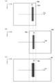
- a filter process (blur process) is performed on the superimposed portion Gae and the superimposed portion Gbe. Therefore, by performing the print control process in the premise Pm2, the following images Gwa and Gwb in a print state and a panoramic image Gw in a superimposed print state are obtained.
- the image Gwa (superimposed portion Gae) in the printing state under the premise Pm2 is as shown in the image Gwa (superimposed portion Gae) in FIG. Note that the printing position of the image Gwa in FIG. 7A is shifted.
- the image Gwb (superimposed portion Gbe) in the printing state in the premise Pm2 is as shown in the image Gwb (superimposed portion Gbe) in FIG. Note that the printing position of the image Gwb in FIG. 7B is shifted. Further, the panoramic image Gw in the superimposed printing state on the premise Pm2 is as shown in FIG. 7C.
- the line X1 indicated by the image Gwa (superimposed portion Gae) in FIG. 7A corresponds to the line X1 in FIG.
- a line X1 indicated by the image Gwa (superimposed portion Gae) in FIG. 7B corresponds to a line X1 in FIG.
- FIG. 8A is a diagram showing the state of the gradation of the line X1 along the arrow line L1a in FIG. 7A by using a gradation line X1a.
- FIG. 8B is a diagram showing the gradation state of the line X1 along the arrow line L1b in FIG. 7B by the gradation line X1b.
- the grayscale lines X1a and X1b show, instead of a rectangular mountain, a mountain having a wide tail as compared with the grayscale line X1an in FIG. 14A and the grayscale line X1bn in FIG. 14B. .
- the panoramic image Gw in FIG. 7C is obtained by combining the image Gwa in FIG. 7A and the image Gwa in FIG. 7A in a situation where the superimposed portion Gbe in FIG. 7B is superimposed on the superimposed portion Gbe in FIG. It is represented by the image Gwb of (b). Therefore, one line X1 is shown in the superimposed region Rw of the panoramic image Gw in the superimposed print state in FIG. 7C.
- the overlapping area Rw in FIG. 7C is an image in which the overlapping section Gbe in FIG. 7B is superimposed on the overlapping section Gae in FIG. 7A.
- FIG. 8C is a diagram showing the gradation state of the line X1 along the arrow line L1c in FIG. 7C by the gradation line X1c.
- the gradation line X1c shows one peak instead of two peaks as compared with the gradation line X1cn in FIG.
- the print control processing filter processing
- the two lines X1 indicated by Rw can be expressed as one line X1 (see FIG. 7C). That is, due to the effect of the filter processing (blur processing), it is possible to suppress the occurrence of a low image quality portion (streak) in the superimposed region Rw of the panoramic image Gw in the superimposed print state.
- the filter process (blurring process) performed on the superimposed portions Gae and Gbe is a process for suppressing a decrease in the image quality of the superimposed region Rw that occurs in a print misalignment situation. That is, the filter processing (blurring processing) performed on the superimposed portions Gae and Gbe is processing for reducing a change in the image quality of the superimposed region Rw that occurs in a print misalignment state.
- the filter process blue process
- the superimposed area Rw of the panoramic image Gw in the superimposed print state is generated. A decrease in image quality can be suppressed.
- the image Gwa has the overlapping portion Gae, which is the rear end of the image Gwa.
- the image Gwb has a superimposed portion Gbe that is a tip of the image Gwb.
- the filter processing unit 23 performs a filtering process on the superimposition unit Gae and the superimposition unit Gbe.
- the panoramic image Gw has a superimposition region Rw.
- the filtering process is a process for reducing a change in image quality of the superimposed region Rw, which occurs in a situation where the superimposed portion Gbe is shifted and overlaps the superimposed portion Gae.
- filter processing (blur processing) is performed on the superimposed portion Gae of the image Gwa and the superimposed portion Gbe of the image Gwb.
- the thermal transfer printer 100 of the present embodiment has a configuration for achieving the above effects. Therefore, the above problem can be solved by the thermal transfer printer 100 of the present embodiment.
- the number of images for expressing the panoramic image Gw in the superimposed print state is two, but is not limited to this.
- the number of images for expressing the panoramic image Gw in the superimposed printing state may be three or more. That is, the panoramic image Gw may be an image represented by a plurality of images including the image Gwa and the image Gwb.
- the panoramic image Gw in the superimposed print state is 3 images are obtained from the panoramic image Gw in the original state.
- the panoramic image Gw is printed by printing the three images so that a part of the three images overlaps.
- the leading end and the trailing end of the second image are used as a superimposing unit.
- configuration Ct1 the configuration of the first embodiment is also referred to as “configuration Ct1”.
- configuration Ctm1 the configuration of this modification is also referred to as “configuration Ctm1”.
- the configuration Ctm1 is configured to perform a filtering process with different characteristics on a superimposed portion of each image acquired from the panoramic image Gw in the original state.
- the sharpness of the superimposed region Rw of the panoramic image Gw in the superimposed print state is lower than the sharpness of the superimposed region Rw of the panoramic image Gw in the original state. That is, in the configuration Ct1, the sharpness of the superimposed region Rw of the panoramic image Gw in the superimposed print state is low. Therefore, in the panoramic image Gw in the superimposed printing state, the sharpness of the superimposed region Rw is different from the sharpness of the region other than the superimposed region Rw. Therefore, depending on the content of the original panoramic image Gw, a step (joint) in density may be conspicuous at the leading end and the trailing end of the superimposition region Rw.
- filter processing Fw filter processing with different characteristics is performed on the superimposed portion Gae and the superimposed portion Gbe.
- the filter processing performed on the superimposition unit Gae is also referred to as “filter processing Fa”.
- the filter processing performed on the superimposing unit Gbe is also referred to as “filter processing Fb”.
- the print control process in the configuration Ctm1 of this modification is different from the print control process in the configuration Ct1 only in the filter process Fw.
- Other processes of the print control process in the configuration Ctm1 are the same as the print control processes in the configuration Ct1, and therefore, detailed description will not be repeated.
- the filter processing unit 23 performs the filter processing Fa on the superimposition unit Gae, and the filter processing unit 23 performs the filter processing Fb on the superimposition unit Gbe.
- the characteristics of the filter processing performed by the filter processing unit 23 on the superimposition unit Gae and the characteristics of the filter processing performed on the superimposition unit Gbe by the filter processing unit 23 are different.
- the filtering process Fa is, for example, a sharpening filtering process.
- the sharpening filter process is a process of amplifying a high-frequency component of an image. That is, the sharpening filter process is a process of enhancing the edge of the image.
- the filter processing Fb is, for example, the aforementioned blur processing.
- the filtering processes Fa and Fb are not limited to the above.
- the filter process Fa may be a blur process
- the filter process Fb may be a sharpening filter process. That is, one of the filtering processes Fa and Fb is a blurring process.
- the filtering process Fa or the filtering process Fb may be a process that emphasizes an edge, which is different from the sharpening filtering process.
- filter processing with different characteristics is performed on each of the superimposed portion Gae and the superimposed portion Gbe.
- the same effect as in the first embodiment can be obtained. That is, even if the printing positions of the images Gwa and Gwb are displaced, it is possible to suppress the occurrence of a low image quality portion (streak) in the superimposition region Rw of the panoramic image Gw in the superimposed printing state. Further, it is possible to make the density step (joint) at the front end and the rear end of the superimposition region Rw inconspicuous.
- the configuration of the second embodiment is also referred to as “configuration Ct2”.
- a low image quality portion (streak, unevenness) generated when there is a shift in the printing position of the images Gwa and Gwb may look different depending on the frequency component of the superimposed portion. When the high frequency component is included in the frequency component of the superimposed portion, the low image quality portion is easily seen.
- the superimposing unit performs the blurring process.
- the sharpness of the superimposition unit is reduced. For this reason, it is not preferable to simply perform the blur processing with a high degree of blur.
- the configuration Ct2 is a configuration in which the filtering process is changed according to the frequency components included in the superimposition unit. For example, when there is a high possibility that a low image quality part will occur, a blur process with a high degree of blur is performed.
- FIG. 9 is a block diagram illustrating a main configuration of a thermal transfer printer 100A according to the second embodiment.
- the thermal transfer printer 100A is different from the thermal transfer printer 100 of FIG. 1 in that a control unit 20A is provided instead of the control unit 20.
- Other configurations and functions of the thermal transfer printer 100A are the same as those of the thermal transfer printer 100, and thus detailed description will not be repeated.
- control unit 20A is different from the control unit 20 in that the control unit 20A further includes a frequency identification unit 25.
- Other configurations and functions of control unit 20A are similar to those of control unit 20, and thus detailed description will not be repeated.
- the frequency specifying unit 25 is a module of a program executed by the control unit 20, for example.
- the frequency specifying unit 25 is realized by the control unit 20 performing various processes according to a program stored in a memory or the like.
- the frequency specifying unit 25 may be configured by a signal processing circuit configured by a hardware electric circuit.
- FIG. 10 is a flowchart of a print control process A according to the second embodiment.
- the processes having the same step numbers as those in FIG. 5 perform the same processes as those described in the first embodiment, and thus detailed description will not be repeated.
- points different from the first embodiment will be mainly described.
- the information processing apparatus 200 transmits a printing instruction and image data D1 indicating the panoramic image Gw in FIG. 6A to the thermal transfer printer 100.
- step S125A a frequency component specifying process is performed.
- the frequency specifying unit 25 specifies (analyzes) a frequency component included in at least one of the superimposed unit Gae and the superimposed unit Gbe.
- the identification (analysis) of the frequency component is a well-known technique performed using, for example, a two-dimensional Fourier transform, and thus a detailed description is omitted.
- a brief description will be given.
- the frequency identification unit 25 obtains a spatial frequency spectrum included in the superimposition unit Gae by performing a two-dimensional Fourier transform on the superimposition unit Gae.
- the frequency specifying unit 25 specifies a frequency component included in the superimposing unit Gae based on the spatial frequency spectrum.
- the frequency specifying unit 25 specifies the frequency components included in the superimposition unit Gbe.
- the frequency specifying unit 25 may specify a frequency component included in only one of the superimposing units Gae and Gbe.
- step S130A a filtering process Fwa is performed.
- the filter processing unit 23 performs a filter processing based on the specified frequency component (spatial frequency spectrum).
- the reference frequency in the spatial frequency spectrum is also referred to as “reference frequency Frn”.
- the reference frequency Frn is a predetermined frequency.
- a frequency that is 0.5 times the maximum frequency that can represent a spatial frequency spectrum is the reference frequency Frn.
- the filter processing unit 23 performs a filter process on the superimposition part Gae and the superimposition part Gbe to reduce the sharpness of the image.
- the filtering process is a blurring process with a high degree of blurring.
- the specified frequency component spatial frequency spectrum
- the filter processing unit 23 performs a filtering process on the superimposed part Gae and the superimposed part Gbe so as to hardly reduce the sharpness of the image.
- the filtering process is a blurring process with a low degree of blurring.
- the filter processing unit 23 performs a blur process on the superimposition unit Gae and the superimposition unit Gbe such that the higher the frequency included in the specified frequency component (spatial frequency spectrum), the greater the degree of blur. You may.
- the frequency identification unit 25 identifies (analyzes) the frequency components included in at least one of the superimposition unit Gae and the superimposition unit Gbe.
- the filter processing unit 23 performs a filter process based on the specified frequency component.
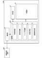
- FIG. 11 is a block diagram illustrating a characteristic functional configuration of the thermal transfer printer BL10.
- the thermal transfer printer BL10 corresponds to one of the thermal transfer printer 100 and the thermal transfer printer 100A. That is, FIG. 11 is a block diagram illustrating main functions of the thermal transfer printer BL10, which are related to the present invention.
- the thermal transfer printer BL10 performs a printing process of printing a panoramic image represented by a plurality of images including the first image and the second image on a sheet using an ink sheet.
- the first image has a first superimposed portion which is a rear end of the first image.
- the second image has a second superimposed portion that is a tip of the second image.
- the panorama image is represented by at least the first image and the second image in a situation where the second superimposition unit is superimposed on the first superimposition unit.
- the thermal transfer printer functionally includes a filter processing unit BL1, a density adjustment unit BL2, and a printing unit BL3.
- the filter processing unit BL1 performs a filtering process on the first superimposing unit and the second superimposing unit.
- the filter processing unit BL1 corresponds to the filter processing unit 23.
- the density adjusting unit BL2 performs a density process of adjusting the density of the first superimposing unit on which the filtering process has been performed and the density of the second superimposing unit on which the filtering process has been performed. This is performed for the second superimposing unit.
- the density adjusting unit BL2 corresponds to the density adjusting unit 24.
- the printing unit BL3 is represented by at least the first image and the second image in a state where the second superimposing unit on which the density processing has been performed is superimposed on the first superimposing unit on which the density processing has been performed.
- the printing process for printing the panoramic image on the paper is performed.
- the printing unit BL3 corresponds to the printing unit 30.
- the panoramic image has a superimposed area.
- the overlapping area is an area for overlapping the second overlapping section on the first overlapping section.
- the filtering process reduces a change in the image quality of the superimposed region, which occurs in a situation where the panoramic image is printed on the sheet and in a situation where the second superimposed portion is shifted and overlaps the first superimposed portion. This is the processing to be performed.
- thermal transfer printer hzs the thermal transfer printer according to the present invention is also referred to as “thermal transfer printer hzs”.
- the thermal transfer printer hzs is one of the thermal transfer printers 100 and 100A.
- the thermal transfer printer hzs may not include all the components shown in the figure. That is, the thermal transfer printer hzs needs to include only the minimum components that can achieve the effects of the present invention.
- the functions of the filter processing unit 23 and the density adjustment unit 24 included in the thermal transfer printer hzs may be realized by a processing circuit.
- the processing circuit is a circuit for performing a filtering process on the first superimposing unit and the second superimposing unit.
- the processing circuit performs a density process for adjusting the density of the first superimposing unit on which the filtering process has been performed and the density of the second superimposing unit on which the filtering process has been performed. And a circuit for performing the second superimposing unit.
- the filtering process reduces a change in the image quality of the superimposed region, which occurs in a situation where the panoramic image is printed on the sheet and in a situation where the second superimposed portion is shifted and overlaps the first superimposed portion. This is the processing to be performed.
- the processing circuit may be dedicated hardware. Further, the processing circuit may be a processor that executes a program stored in a memory.
- the processor is, for example, a CPU (Central Processing Unit), a central processing unit, an arithmetic unit, a microprocessor, a microcomputer, a DSP (Digital Signal Processor), or the like.
- configuration Cs1 the configuration in which the processing circuit is dedicated hardware
- configuration Cs2 the configuration in which the processing circuit is a processor
- configuration Cs3 a configuration in which the functions of the filter processing unit 23 and the density adjustment unit 24 are realized by a combination of hardware and software
- the processing circuit is, for example, a single circuit, a composite circuit, a programmed processor, a parallel programmed processor, an ASIC (Application Specific Integrated Circuit), an FPGA (Field Programmable Gate Array), or a combination thereof.
- the functions of the filter processing unit 23 and the density adjustment unit 24 may be each realized by two processing circuits. Further, all the functions of the filter processing unit 23 and the density adjustment unit 24 may be realized by one processing circuit.
- thermal transfer printer hd10 The configuration in which all or a part of each component included in the thermal transfer printer hzs is represented by hardware is as follows, for example.
- a thermal transfer printer in which all or a part of each component included in the thermal transfer printer hzs is represented by hardware is also referred to as a “thermal transfer printer hd10”.
- FIG. 12 is a hardware configuration diagram of the thermal transfer printer hd10.
- the thermal transfer printer hd10 includes a processor hd1 and a memory hd2.
- the memory hd2 is a nonvolatile or volatile semiconductor memory such as a RAM (Random Access Memory), a ROM (Read Only Memory), a flash memory, an EPROM, and an EEPROM.
- the memory hd2 is, for example, a magnetic disk, a flexible disk, an optical disk, a compact disk, a mini disk, a DVD, or the like. Further, the memory hd2 may be any storage medium used in the future.
- the processing circuit is the processor hd1.
- each function of the filter processing unit 23 and the density adjustment unit 24 is realized by software, firmware, or a combination of software and firmware.
- the software or firmware is described as a program and stored in the memory hd2.
- the processing circuit (processor hd1) reads out the program stored in the memory hd2 and executes the program, thereby realizing the functions of the filter processing unit 23 and the density adjusting unit 24. . That is, the memory hd2 stores the following program.
- the program is a program for causing a processing circuit (processor hd1) to execute a step of performing a filtering process on the first superimposing unit and the second superimposing unit.
- the program performs a density process of adjusting the density of the first superimposing unit on which the filtering process has been performed and the density of the second superimposing unit on which the filtering process has been performed. It is also a program for causing a processing circuit (processor hd1) to execute the steps performed on the second superimposing unit.
- the filtering process reduces a change in the image quality of the superimposed region, which occurs in a situation where the panoramic image is printed on the sheet and in a situation where the second superimposed portion is shifted and overlaps the first superimposed portion. This is the processing to be performed.
- the program also causes the computer to execute a procedure of a process performed by each of the filter processing unit 23 and the density adjustment unit 24, a method of performing the process, and the like.
- the function of the filter processing unit 23 is realized by the processing circuit reading and executing a program stored in the memory. Further, for example, the function of the density adjusting unit 24 is realized by a processing circuit as dedicated hardware.
- the processing circuit can realize the above-described functions by hardware, software, firmware, or a combination thereof.
- the present invention may be realized as a printing method in which the operation of the characteristic components included in the thermal transfer printer hzs is performed as a step. Further, the present invention may be realized as a program for causing a computer to execute each step included in such a printing method. Further, the present invention may be realized as a computer-readable recording medium storing such a program. Further, the program may be distributed via a transmission medium such as the Internet.
- the printing method according to the present invention corresponds to, for example, the print control process of FIG. 5 or the print control process A of FIG.
- the configuration is such that the ink ribbon provided with the protective material 6op is used, but the present invention is not limited to this.
- an ink ribbon without the protective material 6op may be used.
Landscapes
- Electronic Switches (AREA)
- Color, Gradation (AREA)
Abstract
Description
(構成)
図1は、実施の形態1に係る熱転写プリンタ100の主要構成を示すブロック図である。なお、図1には、実施の形態1に関連しない構成要素(例えば、電源)は示されていない。また、図1には、説明のために、熱転写プリンタ100に含まれない情報処理装置200も示される。熱転写プリンタ100は、例えば、熱転写プリンタである。熱転写プリンタ100は、詳細は後述するが、画像を用紙に印刷するための印画処理Pを行う。
次に、パノラマ画像について説明する。パノラマ画像は、2枚以上の画像により表現される画像である。以下においては、パノラマ画像を、「パノラマ画像Gw」ともいう。図4は、パノラマ画像Gwを説明するための図である。なお、図4において、主走査方向はY軸方向であり、副走査方向はX軸方向である。
次に、熱転写プリンタ100が行う処理(以下、「印刷制御処理」ともいう)について説明する。図5は、実施の形態1に係る印刷制御処理のフローチャートである。
以上説明したように、本実施の形態によれば、画像Gwaは、当該画像Gwaの後端部である重畳部Gaeを有する。画像Gwbは、当該画像Gwbの先端部である重畳部Gbeを有する。フィルタ処理部23は、重畳部Gaeおよび重畳部Gbeにフィルタ処理を行う。パノラマ画像Gwは、重畳領域Rwを有する。フィルタ処理は、重畳部Gaeに重畳部Gbeがずれて重なる状況において生じる、重畳領域Rwの画質の変化を小さくする処理である。
以下においては、実施の形態1の構成を、「構成Ct1」ともいう。また、以下においては、本変形例の構成を「構成Ctm1」ともいう。構成Ctm1は、元状態のパノラマ画像Gwから取得される各画像の重畳部に対し、異なる特性のフィルタ処理を行う構成である。
以下においては、実施の形態2の構成を、「構成Ct2」ともいう。画像Gwa,Gwbの印画位置のずれが存在する場合において発生する低画質部(スジ、ムラ)は、重畳部の周波数成分によって見え方が異なることがある。当該重畳部の周波数成分に高周波成分が含まれる場合、低画質部が見えやすくなる。
図11は、熱転写プリンタBL10の特徴的な機能構成を示すブロック図である。熱転写プリンタBL10は、熱転写プリンタBL10は、熱転写プリンタ100および熱転写プリンタ100Aのいずれかに相当する。つまり、図11は、熱転写プリンタBL10の有する機能のうち、本発明に関わる主要な機能を示すブロック図である。
以上、本発明に係る熱転写プリンタについて、各実施の形態および変形例に基づいて説明したが、本発明は、当該各実施の形態および変形例に限定されるものではない。本発明の主旨を逸脱しない範囲内で、当業者が思いつく変形を各実施の形態および変形例に施したものも、本発明に含まれる。つまり、本発明は、その発明の範囲内において、各実施の形態、変形例を自由に組み合わせたり、各実施の形態、変形例を適宜、変形、省略することが可能である。
Claims (8)
- インクシート(6)を使用して、第1画像(Gwa)および第2画像(Gwb)を含む複数の画像により表現されるパノラマ画像(Gw)を用紙(2)に印刷する印画処理を行う熱転写プリンタであって、
前記第1画像(Gwa)は、当該第1画像(Gwa)の後端部である第1重畳部(Gae)を有し、
前記第2画像(Gwb)は、当該第2画像(Gwb)の先端部である第2重畳部(Gbe)を有し、
前記パノラマ画像(Gw)は、前記第1重畳部(Gae)に前記第2重畳部(Gbe)を重ねた状況において、少なくとも前記第1画像(Gwa)および前記第2画像(Gwb)により表現され、
前記熱転写プリンタは、
前記第1重畳部(Gae)および前記第2重畳部(Gbe)にフィルタ処理を行うフィルタ処理部(23)と、
前記フィルタ処理が行われた前記第1重畳部(Gae)の濃度、および、当該フィルタ処理が行われた前記第2重畳部(Gbe)の濃度を調整する濃度処理を、当該第1重畳部(Gae)および当該第2重畳部(Gbe)に対して行う濃度調整部(24)と、
前記濃度処理が行われた前記第1重畳部(Gae)に当該濃度処理が行われた前記第2重畳部(Gbe)を重ねた状況において、少なくとも前記第1画像(Gwa)および前記第2画像(Gwb)により表現される前記パノラマ画像(Gw)を前記用紙(2)に印刷する前記印画処理を行う印画部(30)とを備え、
前記パノラマ画像(Gw)は、重畳領域(Rw)を有し、
前記重畳領域(Rw)は、前記第1重畳部(Gae)に前記第2重畳部(Gbe)を重ねるための領域であり、
前記フィルタ処理は、前記用紙(2)に前記パノラマ画像(Gw)が印刷される状況であって、かつ、前記第1重畳部(Gae)に前記第2重畳部(Gbe)がずれて重なる状況において生じる、前記重畳領域(Rw)の画質の変化を小さくする処理である、
熱転写プリンタ。 - 前記濃度調整部(24)は、前記フィルタ処理が行われた前記第1重畳部(Gae)に、当該フィルタ処理が行われた前記第2重畳部(Gbe)を重ねた場合に生じる、前記重畳領域(Rw)の濃度変化を小さくするための前記濃度処理を、当該第1重畳部(Gae)および当該第2重畳部(Gbe)に対して行う
請求項1に記載の熱転写プリンタ。 - 画像としての前記第1重畳部(Gae)に行われる前記フィルタ処理、および、当該画像としての前記第2重畳部(Gbe)に行われる当該フィルタ処理の各々は、当該画像の鮮鋭度を低下させるぼかし処理である
請求項1または2に記載の熱転写プリンタ。 - 前記フィルタ処理部(23)が前記第1重畳部(Gae)に行う前記フィルタ処理の特性と、当該フィルタ処理部(23)が前記第2重畳部(Gbe)に行う当該フィルタ処理の特性は異なる
請求項1または2に記載の熱転写プリンタ。 - 画像としての前記第1重畳部(Gae)に行われる前記フィルタ処理、および、当該画像としての前記第2重畳部(Gbe)に行われる当該フィルタ処理の一方は、当該画像の鮮鋭度を低下させるぼかし処理である
請求項4に記載の熱転写プリンタ。 - 前記熱転写プリンタは、さらに、
前記第1重畳部(Gae)および前記第2重畳部(Gbe)の少なくとも一方に含まれる周波数成分を特定する周波数特定部(25)を備え、
前記フィルタ処理部(23)は、特定された前記周波数成分に基づいた前記フィルタ処理を行う
請求項1または2に記載の熱転写プリンタ。 - 前記フィルタ処理部(23)は、特定された前記周波数成分が予め定められた周波数より高い高周波成分を含む場合、画像としての前記第1重畳部(Gae)および前記第2重畳部(Gbe)に対して、当該画像の鮮鋭度を低下させる前記フィルタ処理を行う
請求項6に記載の熱転写プリンタ。 - インクシート(6)を使用して、第1画像(Gwa)および第2画像(Gwb)を含む複数の画像により表現されるパノラマ画像(Gw)を用紙(2)に印刷する印画処理を行う熱転写プリンタが行う印画方法であって、
前記第1画像(Gwa)は、当該第1画像(Gwa)の後端部である第1重畳部(Gae)を有し、
前記第2画像(Gwb)は、当該第2画像(Gwb)の先端部である第2重畳部(Gbe)を有し、
前記パノラマ画像(Gw)は、前記第1重畳部(Gae)に前記第2重畳部(Gbe)を重ねた状況において、少なくとも前記第1画像(Gwa)および前記第2画像(Gwb)により表現され、
前記印画方法は、
前記第1重畳部(Gae)および前記第2重畳部(Gbe)にフィルタ処理を行うステップ(S130)と、
前記フィルタ処理が行われた前記第1重畳部(Gae)の濃度、および、当該フィルタ処理が行われた前記第2重畳部(Gbe)の濃度を調整する濃度処理を、当該第1重畳部(Gae)および当該第2重畳部(Gbe)に対して行うステップ(S140)と、
前記濃度処理が行われた前記第1重畳部(Gae)に当該濃度処理が行われた前記第2重畳部(Gbe)を重ねた状況において、少なくとも前記第1画像(Gwa)および前記第2画像(Gwb)により表現される前記パノラマ画像(Gw)を前記用紙(2)に印刷する前記印画処理を行うステップ(S150)とを備え、
前記パノラマ画像(Gw)は、重畳領域(Rw)を有し、
前記重畳領域(Rw)は、前記第1重畳部(Gae)に前記第2重畳部(Gbe)を重ねるための領域であり、
前記フィルタ処理は、前記用紙(2)に前記パノラマ画像(Gw)が印刷される状況であって、かつ、前記第1重畳部(Gae)に前記第2重畳部(Gbe)がずれて重なる状況において生じる、前記重畳領域(Rw)の画質の変化を小さくする処理である、
印画方法。
Priority Applications (4)
| Application Number | Priority Date | Filing Date | Title |
|---|---|---|---|
| CN201880095434.0A CN112368153A (zh) | 2018-07-13 | 2018-07-13 | 热转印打印机和印相方法 |
| JP2020529949A JPWO2020012640A1 (ja) | 2018-07-13 | 2018-07-13 | 熱転写プリンタおよび印画方法 |
| US17/050,810 US20210229460A1 (en) | 2018-07-13 | 2018-07-13 | Thermal transfer printer and printing method |
| PCT/JP2018/026497 WO2020012640A1 (ja) | 2018-07-13 | 2018-07-13 | 熱転写プリンタおよび印画方法 |
Applications Claiming Priority (1)
| Application Number | Priority Date | Filing Date | Title |
|---|---|---|---|
| PCT/JP2018/026497 WO2020012640A1 (ja) | 2018-07-13 | 2018-07-13 | 熱転写プリンタおよび印画方法 |
Publications (1)
| Publication Number | Publication Date |
|---|---|
| WO2020012640A1 true WO2020012640A1 (ja) | 2020-01-16 |
Family
ID=69141553
Family Applications (1)
| Application Number | Title | Priority Date | Filing Date |
|---|---|---|---|
| PCT/JP2018/026497 Ceased WO2020012640A1 (ja) | 2018-07-13 | 2018-07-13 | 熱転写プリンタおよび印画方法 |
Country Status (4)
| Country | Link |
|---|---|
| US (1) | US20210229460A1 (ja) |
| JP (1) | JPWO2020012640A1 (ja) |
| CN (1) | CN112368153A (ja) |
| WO (1) | WO2020012640A1 (ja) |
Citations (6)
| Publication number | Priority date | Publication date | Assignee | Title |
|---|---|---|---|---|
| US5450099A (en) * | 1993-04-08 | 1995-09-12 | Eastman Kodak Company | Thermal line printer with staggered head segments and overlap compensation |
| JP2004082610A (ja) | 2002-08-28 | 2004-03-18 | Shinko Electric Co Ltd | 熱転写プリント方法 |
| WO2011125134A1 (ja) | 2010-04-09 | 2011-10-13 | 三菱電機株式会社 | 熱転写プリント装置 |
| JP2016182783A (ja) * | 2015-03-26 | 2016-10-20 | シチズンホールディングス株式会社 | 熱転写プリンタおよびその制御方法 |
| JP2016182676A (ja) * | 2015-03-25 | 2016-10-20 | 三菱電機株式会社 | 熱転写プリント装置及びコンピュータ及び熱転写プリント方法及び画像データ変換方法及び画像データ処理プログラム |
| WO2018078743A1 (ja) * | 2016-10-26 | 2018-05-03 | 三菱電機株式会社 | サーマルプリンタおよびサーマルプリンタの制御方法 |
-
2018
- 2018-07-13 JP JP2020529949A patent/JPWO2020012640A1/ja not_active Withdrawn
- 2018-07-13 WO PCT/JP2018/026497 patent/WO2020012640A1/ja not_active Ceased
- 2018-07-13 CN CN201880095434.0A patent/CN112368153A/zh not_active Withdrawn
- 2018-07-13 US US17/050,810 patent/US20210229460A1/en not_active Abandoned
Patent Citations (6)
| Publication number | Priority date | Publication date | Assignee | Title |
|---|---|---|---|---|
| US5450099A (en) * | 1993-04-08 | 1995-09-12 | Eastman Kodak Company | Thermal line printer with staggered head segments and overlap compensation |
| JP2004082610A (ja) | 2002-08-28 | 2004-03-18 | Shinko Electric Co Ltd | 熱転写プリント方法 |
| WO2011125134A1 (ja) | 2010-04-09 | 2011-10-13 | 三菱電機株式会社 | 熱転写プリント装置 |
| JP2016182676A (ja) * | 2015-03-25 | 2016-10-20 | 三菱電機株式会社 | 熱転写プリント装置及びコンピュータ及び熱転写プリント方法及び画像データ変換方法及び画像データ処理プログラム |
| JP2016182783A (ja) * | 2015-03-26 | 2016-10-20 | シチズンホールディングス株式会社 | 熱転写プリンタおよびその制御方法 |
| WO2018078743A1 (ja) * | 2016-10-26 | 2018-05-03 | 三菱電機株式会社 | サーマルプリンタおよびサーマルプリンタの制御方法 |
Also Published As
| Publication number | Publication date |
|---|---|
| US20210229460A1 (en) | 2021-07-29 |
| JPWO2020012640A1 (ja) | 2021-01-07 |
| CN112368153A (zh) | 2021-02-12 |
Similar Documents
| Publication | Publication Date | Title |
|---|---|---|
| JP6377003B2 (ja) | 熱転写プリンタおよびその制御方法 | |
| US10511741B2 (en) | Image processing apparatus, image processing method, and non-transitory computer-readable medium | |
| US8976408B2 (en) | Apparatus, method, and computer-readable storage medium for maintaining reproducibility of lines or characters of image | |
| JP6844064B2 (ja) | プリンタおよび印刷制御方法 | |
| WO2020012640A1 (ja) | 熱転写プリンタおよび印画方法 | |
| JP5796328B2 (ja) | 印刷用画像データ生成装置、熱転写プリンタ及びコンピュータプログラム | |
| JP5953866B2 (ja) | 印刷システムおよび画像形成装置 | |
| JP2005130379A (ja) | 画像変倍方法とこの方法を実施する写真プリント装置 | |
| US8488187B2 (en) | Image forming apparatus and method for forming image | |
| JPWO2019008706A1 (ja) | 熱転写プリンターおよび印刷制御方法 | |
| JP6753296B2 (ja) | 画像処理装置及び画像形成装置 | |
| JP6203017B2 (ja) | サーマルプリンタおよび画像データ処理方法 | |
| WO2020070802A1 (ja) | 熱転写プリント装置、熱転写プリント装置のキャリブレーション方法および印画方法 | |
| JP2026019356A (ja) | 画像処理装置、画像処理方法、及びプログラム | |
| EP3738777B1 (en) | Thermal printer and printing method | |
| JP6769266B2 (ja) | 画像形成装置 | |
| JP2014008770A (ja) | 記録装置 | |
| JP2025074005A (ja) | 印刷された小さなテキスト | |
| JP3920122B2 (ja) | 画像処理方法および装置、画像処理システム並びにプログラム | |
| JP2007320050A (ja) | 印刷装置及び印刷方法 | |
| JP4126631B2 (ja) | 写真焼付装置 | |
| JP2004082334A (ja) | プリント方法 | |
| JP2017177361A (ja) | 画像形成装置、画像形成方法および制御プログラム | |
| JP2013184378A (ja) | 昇華型プリンタにおいて印画シワを軽減するプリンタ制御手法 | |
| JP2009100221A (ja) | 画像処理装置、画像処理システムおよび画像処理プログラム |
Legal Events
| Date | Code | Title | Description |
|---|---|---|---|
| 121 | Ep: the epo has been informed by wipo that ep was designated in this application |
Ref document number: 18925963 Country of ref document: EP Kind code of ref document: A1 |
|
| ENP | Entry into the national phase |
Ref document number: 2020529949 Country of ref document: JP Kind code of ref document: A |
|
| NENP | Non-entry into the national phase |
Ref country code: DE |
|
| ENP | Entry into the national phase |
Ref document number: 2018925963 Country of ref document: EP Effective date: 20210215 |
|
| 122 | Ep: pct application non-entry in european phase |
Ref document number: 18925963 Country of ref document: EP Kind code of ref document: A1 |