WO2020012764A1 - トルクセンサ - Google Patents
トルクセンサ Download PDFInfo
- Publication number
- WO2020012764A1 WO2020012764A1 PCT/JP2019/018146 JP2019018146W WO2020012764A1 WO 2020012764 A1 WO2020012764 A1 WO 2020012764A1 JP 2019018146 W JP2019018146 W JP 2019018146W WO 2020012764 A1 WO2020012764 A1 WO 2020012764A1
- Authority
- WO
- WIPO (PCT)
- Prior art keywords
- torque sensor
- sensor
- strain
- torque
- thickness
- Prior art date
- Legal status (The legal status is an assumption and is not a legal conclusion. Google has not performed a legal analysis and makes no representation as to the accuracy of the status listed.)
- Ceased
Links
Images


Classifications
-
- G—PHYSICS
- G01—MEASURING; TESTING
- G01L—MEASURING FORCE, STRESS, TORQUE, WORK, MECHANICAL POWER, MECHANICAL EFFICIENCY, OR FLUID PRESSURE
- G01L3/00—Measuring torque, work, mechanical power, or mechanical efficiency, in general
- G01L3/02—Rotary-transmission dynamometers
- G01L3/04—Rotary-transmission dynamometers wherein the torque-transmitting element comprises a torsionally-flexible shaft
- G01L3/10—Rotary-transmission dynamometers wherein the torque-transmitting element comprises a torsionally-flexible shaft involving electric or magnetic means for indicating
- G01L3/108—Rotary-transmission dynamometers wherein the torque-transmitting element comprises a torsionally-flexible shaft involving electric or magnetic means for indicating involving resistance strain gauges
-
- G—PHYSICS
- G01—MEASURING; TESTING
- G01L—MEASURING FORCE, STRESS, TORQUE, WORK, MECHANICAL POWER, MECHANICAL EFFICIENCY, OR FLUID PRESSURE
- G01L3/00—Measuring torque, work, mechanical power, or mechanical efficiency, in general
- G01L3/02—Rotary-transmission dynamometers
- G01L3/14—Rotary-transmission dynamometers wherein the torque-transmitting element is other than a torsionally-flexible shaft
- G01L3/1407—Rotary-transmission dynamometers wherein the torque-transmitting element is other than a torsionally-flexible shaft involving springs
- G01L3/1428—Rotary-transmission dynamometers wherein the torque-transmitting element is other than a torsionally-flexible shaft involving springs using electrical transducers
- G01L3/1457—Rotary-transmission dynamometers wherein the torque-transmitting element is other than a torsionally-flexible shaft involving springs using electrical transducers involving resistance strain gauges
-
- B—PERFORMING OPERATIONS; TRANSPORTING
- B25—HAND TOOLS; PORTABLE POWER-DRIVEN TOOLS; MANIPULATORS
- B25J—MANIPULATORS; CHAMBERS PROVIDED WITH MANIPULATION DEVICES
- B25J13/00—Controls for manipulators
- B25J13/08—Controls for manipulators by means of sensing devices, e.g. viewing or touching devices
- B25J13/085—Force or torque sensors
-
- G—PHYSICS
- G01—MEASURING; TESTING
- G01L—MEASURING FORCE, STRESS, TORQUE, WORK, MECHANICAL POWER, MECHANICAL EFFICIENCY, OR FLUID PRESSURE
- G01L5/00—Apparatus for, or methods of, measuring force, work, mechanical power, or torque, specially adapted for specific purposes
- G01L5/0061—Force sensors associated with industrial machines or actuators
- G01L5/0076—Force sensors associated with manufacturing machines
-
- G—PHYSICS
- G01—MEASURING; TESTING
- G01L—MEASURING FORCE, STRESS, TORQUE, WORK, MECHANICAL POWER, MECHANICAL EFFICIENCY, OR FLUID PRESSURE
- G01L5/00—Apparatus for, or methods of, measuring force, work, mechanical power, or torque, specially adapted for specific purposes
- G01L5/22—Apparatus for, or methods of, measuring force, work, mechanical power, or torque, specially adapted for specific purposes for measuring the force applied to control members, e.g. control members of vehicles, triggers
- G01L5/226—Apparatus for, or methods of, measuring force, work, mechanical power, or torque, specially adapted for specific purposes for measuring the force applied to control members, e.g. control members of vehicles, triggers to manipulators, e.g. the force due to gripping
-
- B—PERFORMING OPERATIONS; TRANSPORTING
- B25—HAND TOOLS; PORTABLE POWER-DRIVEN TOOLS; MANIPULATORS
- B25J—MANIPULATORS; CHAMBERS PROVIDED WITH MANIPULATION DEVICES
- B25J19/00—Accessories fitted to manipulators, e.g. for monitoring, for viewing; Safety devices combined with or specially adapted for use in connection with manipulators
- B25J19/02—Sensing devices
Definitions
- the embodiment of the present invention relates to a torque sensor applied to, for example, a robot arm or the like.
- the torque sensor has a first structure to which a torque is applied, a second structure to which the torque is output, and a plurality of strain generating portions as beams connecting the first structure and the second structure.
- a plurality of strain gauges as sensor elements are arranged in these strain generating portions.
- a bridge circuit is configured by these strain gauges (see, for example, Patent Documents 1, 2, and 3).
- JP 2013-097735 A JP-A-2005-049209 JP, 2017-172983, A JP 2010-169586 A
- a disc-shaped torque sensor has a first structure, a second structure, and a third structure between the first structure and the second structure, and the first structure and the second structure.
- a strain-generating body as a sensor and a strain gauge are provided in between.
- the torque sensor includes a torque sensor.
- a bending moment accompanying the transfer weight of the robot arm and the load, a motion acceleration, and a reaction force load are applied.
- the gauges are arranged such that the distortion becomes symmetric.
- asymmetric displacement strain occurs due to structural asymmetry and load asymmetry. For this reason, the sensor output is generated by the interference of the other axis, and the detection accuracy of the torque sensor is reduced.
- the embodiment of the present invention provides a torque sensor capable of improving detection accuracy.
- the torque sensor according to the present embodiment includes a first structure, a second structure, a third structure provided between the first structure and the second structure, and a first structure. At least two sensor units provided between the first and second structures, and one of the first structure and the second structure near the sensor unit has a rigidity far from the sensor unit. It is higher than the other of the first structure and the second structure.
- FIG. 2 is a perspective view showing an example of a robot arm to which the first embodiment is applied.
- FIG. 2 is a plan view showing an example of the torque sensor according to the first embodiment.
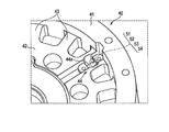
- the side view of FIG. The perspective view which expands and shows the part shown by A of FIG.
- FIG. 9 is a plan view illustrating an example of a torque sensor according to a second embodiment.
- FIG. 6 is an exemplary exploded perspective view showing a main part of FIG. 5;
- FIG. 7 is a sectional view taken along the line VII-VII in FIG. 5.
- FIG. 9 is a view for explaining effects of the second embodiment.
- the figure which shows the comparative example of FIG. FIG. 9 is a view for explaining effects of the second embodiment.
- FIG. 13 is a perspective view showing a modification of the third embodiment, in which main parts are exploded and shown.
- FIG. 1 shows an example of an articulated robot, that is, a robot arm 30.
- the robot arm 30 includes, for example, a base 31, a first arm 32, a second arm 33, a third arm 34, a fourth arm 35, a first drive unit 36, a second drive unit 37 as a drive source, and a third drive unit. 38, and a fourth driving unit 39.
- the configuration of the robot arm 30 is not limited to this, and can be deformed.
- the first arm 32 is rotatable with respect to the base 31 by the first drive unit 36 provided on the first joint J1.
- the second arm 33 is rotatable with respect to the first arm 32 by a second driving unit 37 provided at the second joint J2.
- the third arm 34 is rotatable with respect to the second arm 33 by a third drive unit 38 provided at the third joint J3.
- the fourth arm 35 is rotatably provided with respect to the third arm 34 by a fourth drive unit 39 provided at the fourth joint J4. Hands and various tools (not shown) are mounted on the fourth arm 35.
- the first to fourth driving units 36 to 39 include, for example, a motor, a reduction gear, and a torque sensor, which will be described later.
- (1st Embodiment) 2 to 5 show a disk-shaped torque sensor 40 according to the first embodiment.
- the torque sensor 40 is provided in, for example, the first drive unit 36 of the robot arm 30.
- the torque sensor 40 can be provided in, for example, the second drive unit 37 to the fourth drive unit 39 of the robot arm 30.
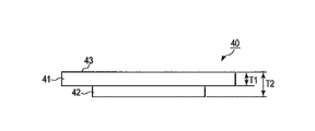
- the torque sensor 40 includes a first structure 41, a second structure 42, a plurality of third structures 43, a first strain sensor 44 and a second strain sensor 45 as a sensor unit, and the like.
- the first structure 41 and the second structure 42 are formed in a ring shape, and the diameter of the second structure 42 is smaller than the diameter of the first structure 41.
- the second structure 42 is arranged concentrically with the first structure 41, and the first structure 41 and the second structure 42 are connected by a third structure 43 as a plurality of radially arranged beams. Have been.
- the plurality of third structures 43 transmit torque between the first structure 41 and the second structure 42.
- the second structure 42 has a hollow portion 42a, and, for example, a wiring (not shown) is passed through the hollow portion 42a.
- the first arm 32 to which the torque sensor 40 is attached is made of, for example, aluminum. Therefore, the first structure 41, the second structure 42, and the plurality of third structures 43 are made of a metal material having a higher Young's modulus than aluminum, for example, stainless steel. If a sufficient mechanical strength can be obtained, materials other than metal can be used.
- a first strain sensor 44 and a second strain sensor 45 are provided between the first structure 41 and the second structure 42.
- One end of a strain body 44a constituting the first strain sensor 44 and one end of a strain body 45a constituting the second strain sensor 45 are respectively joined to the first structure 41, and the other ends of the strain bodies 44a, 45a. The parts are respectively joined to the second structure 42.
- the thickness of the strain body 44a and the strain body 45a is smaller than the thickness of the first structure 41, the second structure 42, and the plurality of third structures 43.
- the first strain sensor 44 and the second strain sensor 45 are arranged at symmetrical positions with respect to the center of the first structure 41 and the second structure 42 (the center of action of torque). In other words, the first strain sensor 44 and the second strain sensor 45 are arranged on the diameter of the first and second annular structures 41 and 42.
- a plurality of strain gauges described later are provided on the surface of the strain body 44a and the strain body 45a.
- Each strain gauge of the strain body 44a and the strain body 45a forms a bridge circuit.
- the strain body 44a and the strain body 45a are respectively connected to a flexible substrate (not shown).
- the flexible board is connected to a printed board (not shown) covered by a cover 46.
- An operational amplifier for amplifying the output voltages of the two bridge circuits is disposed on the printed circuit board. Since the circuit configuration is not the essence of the present embodiment, the description is omitted.
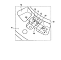
- FIG. 4 shows the region A shown in FIG. 2 in an enlarged manner.
- four strain gauges 51, 52, 53, and 54 as sensor elements are provided on the surface of the strain body 44a.
- a bridge circuit is formed by the four strain gauges 51, 52, 53, 54.
- the strain gauges 51, 52, 53, and 54 are closer to, for example, the second structure 42 than the central portion CT of the effective length (length of a portion acting as a strain generator) L of the strain generator 44a.
- This area AR1 is an area where a large strain is generated in the flexure element 44a within the range of the effective length L of the flexure element 44a, and the first strain sensor 44 responds to a force other than the torque, for example, a force in the Fx and My directions.
- This is an area where the sensitivity and the sensitivity of the first strain sensor 44 in the torque (Mz) direction are the same.
- the detection side the side closer to the strain gauges 51, 52, 53, 54
- the second structure 42 corresponds to the detection side.
- the second strain sensor 45 also has the same configuration as the first strain sensor 44, and the second structure 42 also corresponds to the detection side in the second strain sensor 45.
- the rigidity of the structure on the detection side of the torque sensor 40 is higher than the rigidity of the other structures. That is, in the torque sensor 40, the rigidity of the second structure 42 is higher than the rigidities of the first structure 41 and the third structure 43.
- the thickness T2 of the second structure 42 is larger than the thickness T1 of the first structure 41 and the third structure 43.
- the first structure 41 of the torque sensor 40 having the above-described configuration is provided with, for example, the first arm 32, and the second structure 42 is connected to the base 31 via the first drive unit 36 including a motor and a speed reducer (not shown). Fixed to. However, it is also possible to fix the first structure 41 of the torque sensor 40 to the base 31 via the first drive unit 36 and fix the second structure 42 to, for example, the first arm 32.
- the thickness of the second structure 42 is made larger than the thickness of the first structure 41 and the third structure 43.
- the present invention is not limited to this, and the second structure 42 may be made of a material having a higher Young's modulus than the first structure 41 and the third structure 43. In this case, the second structure 42 does not need to be thicker than the first structure 41 and the third structure 43, and may be smaller than the thickness of the first structure 41 and the third structure 43.
- the strain gauges 51, 52, 53, and 54 constituting the first strain sensor 44 and the second strain sensor 45 are located on the side closer to the second structure 42 than the effective length of the strain body 44a.
- the second structure 42 close to the strain gauges 51, 52, 53, 54 has higher rigidity than the first structure 41 and the third structure 43.
- the weight of the torque sensor 40 can be reduced in order to obtain necessary performance as compared with the case where the overall thickness of the torque sensor 40 is increased.
- the thickness of the second structure 42 is increased without increasing the overall thickness of the torque sensor 40, it is possible to prevent the first drive unit 36 to which the torque sensor 40 is attached from increasing in thickness. It is.
- (2nd Embodiment) 5 and 6 show a second embodiment.
- the thickness of the second structural body 42 is increased. 43 was made thicker.
- the thicknesses of the first structure 41, the second structure 42, and the third structure 43 of the torque sensor 40 are equal as shown in FIG.
- an adapter 60 as a reinforcing member is attached to the second structure 42.
- the ring-shaped adapter 60 is fixed to one surface of the second structure 42 by, for example, a plurality of screws 61.
- the material of the adapter 60 is the same as the material of the torque sensor 40 or a material having a higher Young's modulus than the material of the torque sensor 40.
- the screw 61 is arranged at a position separated from the diameter (Y axis) connecting the first strain sensor 44 and the second strain sensor 45 is shown.
- the two screws 61 are arranged at, for example, symmetric positions with respect to a diameter (Y axis) connecting the first strain sensor 44 and the second strain sensor 45.
- FIG. 7 shows a positional relationship between the two screws 61 arranged near the first strain sensor 44 and the strain body 44a.
- the two screws 61 are arranged at symmetrical positions about the strain element 44a (Y axis).
- the portion corresponding to the first strain sensor 44 is increased in thickness by the adapter 60, so that the vicinity of the first strain sensor 44 is increased.
- the secondary pole moment increases, making it difficult to twist. For this reason, when the rotational moment My is applied to the torque sensor 40 about the Y axis, the torsion generated in the fastening portion 62 located between the two screws 61 can be reduced, and the influence of the other axis interference can be reduced.
- FIG. 5 shows a case where two screws 61 are arranged at positions symmetrical with respect to the first strain sensor 44, but the screws 61 may be arranged on a line connecting the first strain sensor 44 and the second strain sensor 45. good. However, by arranging the screw 61 at a position other than on the line connecting the first strain sensor 44 and the second strain sensor 45, the secondary pole moment can be increased, and the twist becomes more difficult.
- an adapter 60 different from the torque sensor 40 is used. For this reason, it is easy to adjust the rigidity of the adapter 60 according to use conditions. It is possible to easily set the optimum rigidity according to the use conditions.
- the thickness of the adapter 60 can be reduced to obtain necessary rigidity. Therefore, the thickness of the torque sensor 40 can be further reduced.
- the shape of the adapter 60 is annular as in the case of the torque sensor 40, the processing is easy, so that the number of processing steps can be reduced and the increase in manufacturing cost can be suppressed.
- a plurality of screws 61 for fixing the adapter 60 to the second structure 42 are symmetrically arranged with respect to the first strain sensor 44 and the second strain sensor 45, respectively. Therefore, when a rotational moment My about the Y axis is applied to the torque sensor 40, the torque is generated at the fastening portion 62 located between the two screws 61 corresponding to the first strain sensor 44 and the second strain sensor 45, respectively. Twist can be reduced. Therefore, it is possible to reduce the influence of other-axis interference and improve the torque detection accuracy.
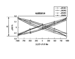
- FIG. 8 shows strain gauges 51, 52, 53, 54 when rotational torque (input moment) My is applied to torque sensor 40 symmetrically about the Y axis in a state where adapter 60 is attached to torque sensor 40.
- 3 shows the rate of change of resistance.
- R1, R2, R3, and R4 indicate the resistances of the strain gauges 51, 52, 53, and 54, respectively.
- FIG. 8 shows the result of applying the torque twice to the torque sensor 40 because the change in the resistance to the torque has a hysteresis.
- FIG. 9 shows a comparative example of FIG. 8, and shows a rate of change in resistance when the adapter 60 is removed from the torque sensor 40.
- FIG. 10 shows the rate of change of resistance when the thickness of the adapter 60 is changed.
- the width W of the rate of change of resistance when there is no adapter 60 shown in FIG. 9 is described as 100%, and the average value of the rate of change of resistance when the thickness of the adapter 60 is, for example, 5 mm and 10 mm is shown.
- N indicates a case where there is no adapter 60.
- FIG. 11 shows a third embodiment.
- the area AR1 in which the strain gauges 51, 52, 53, 54 are arranged is near the second structure 42, and the second structure 42 corresponds to the detection side.
- the rigidity of the second structure 42 is set higher than the rigidity of the first structure 41 and the third structure 43.
- the region where the strain gauges 51, 52, 53, 54 are arranged is near the first structure 41 as shown in FIG. 11, and the first structure 41 corresponds to the detection side. .
- the strain gauge of the second strain sensor 45 is also arranged near the first structure 41 like the strain gauge of the first strain sensor 44.
- the rigidity of the first structure 41 as the detection side is made higher than the rigidity of the second structure 42 and the third structure 43.
- the thickness of the first structure 41 is made larger than the thickness of the second structure 42 and the third structure 43.
- the material of the first structure 41 can be formed of a material having a high Young's modulus, as in the first embodiment.
- a ring-shaped adapter 70 as a reinforcing member can be attached to one surface of the first structure 41 with a plurality of screws 71, as in the second embodiment.
- the thicknesses of the first structure 41, the second structure 42, and the third structure 43 are equal.
- the thickness of the portion corresponding to the first strain sensor 44 increases, so that the secondary pole moment increases, and the fastening portion is reduced. It becomes difficult to twist. For this reason, when the rotational moment My is applied to the torque sensor 40 about the Y axis, it is possible to reduce the torsion generated in the fastening portion located between the two screws 71, and it is possible to reduce the influence of other axis interference.
- the screw 71 may be arranged on a line connecting the first strain sensor 44 and the second strain sensor 45. However, by arranging the screw 71 at a position other than on the line connecting the first strain sensor 44 and the second strain sensor 45, the secondary pole moment can be increased, and the twist becomes more difficult.
- the present invention is not limited to the above embodiments as they are, and may be embodied by modifying the components without departing from the scope of the invention at the stage of implementation.
- Various inventions can be formed by appropriately combining a plurality of constituent elements disclosed in the above embodiments. For example, some components may be deleted from all the components shown in the embodiment. Further, components of different embodiments may be appropriately combined.
Landscapes
- Physics & Mathematics (AREA)
- General Physics & Mathematics (AREA)
- Chemical & Material Sciences (AREA)
- Analytical Chemistry (AREA)
- Engineering & Computer Science (AREA)
- Human Computer Interaction (AREA)
- Robotics (AREA)
- Mechanical Engineering (AREA)
- Manipulator (AREA)
- Force Measurement Appropriate To Specific Purposes (AREA)
- Power Steering Mechanism (AREA)
Abstract
検出精度を向上させることが可能なトルクセンサを提供する。トルクセンサ40は、第1構造体41と、第2構造体42と、第1構造体と第2構造体との間に設けられた第3構造体43と、第1構造体と第2構造体との間に設けられた少なくとも2つのセンサ部44、45と、を具備し、第1構造体と第2構造体のうちセンサ部に近い一方の剛性が他方の剛性より高い。
Description
本発明の実施形態は、例えばロボットアーム等に適用されるトルクセンサに関する。
トルクセンサは、トルクが印加される第1構造体と、トルクが出力される第2構造体と、第1構造体と第2構造体とを連結する梁としての複数の起歪部とを有し、これら起歪部にセンサ素子としての複数の歪ゲージが配置されている。これら歪ゲージによりブリッジ回路が構成されている(例えば特許文献1、2、3参照)。
自動車のエンジン等の出力部に生じるトルクを測定するトルク量変換器において、トルク以外の曲げ応力の影響を低減する技術が開発されている(例えば特許文献4参照)。
例えば円盤状のトルクセンサは、第1構造体と第2構造体と、第1構造体と第2構造体との間の第3構造体とを有し、第1構造体と第2構造体との間にセンサとしての起歪体や、歪ゲージが設けられる。
第1構造体をロボットアームの例えば基台にモータや減速機を含む駆動部を介して固定し、第2構造体をロボットアームの例えばアームに固定して使用する場合、トルクセンサには、トルク以外に、ロボットアームの搬送重量と負荷までの距離、及び動作加速度に伴う曲げモーメントや、その反力の荷重が加わる。
このように、トルクセンサにトルク以外の曲げモーメントや荷重(X軸方向Fx、Y軸方向Fy、Z軸方向Fz)すなわち並進力が印加されると、歪が対称になるようなゲージ配置をしているが、構造非対称・負荷非対称のために非対称な変位(歪)が生じる。このため、他軸干渉によって、センサ出力が発生し、トルクセンサの検出精度が低下していた。
本発明の実施形態は、検出精度を向上させることが可能なトルクセンサを提供する。
本実施形態のトルクセンサは、第1構造体と、第2構造体と、前記第1構造体と前記第2構造体との間に設けられた第3構造体と、前記第1構造体と前記第2構造体との間に設けられた少なくとも2つのセンサ部と、を具備し、前記センサ部に近い前記第1構造体と前記第2構造体の一方の剛性は、前記センサ部から遠い前記第1構造体と前記第2構造体の他方より高い。
以下、実施の形態について、図面を参照して説明する。図面において、同一部分には同一符号を付している。
先ず、図1、図2を参照して、本実施形態が適用されるロボットアーム30、及びトルクセンサ40について説明する。
図1は、多関節ロボット、すなわち、ロボットアーム30の一例を示している。ロボットアーム30は、例えば基台31、第1アーム32、第2アーム33、第3アーム34、第4アーム35、駆動源としての第1駆動部36、第2駆動部37、第3駆動部38、第4駆動部39を具備している。しかし、ロボットアーム30の構成は、これに限定されるものではなく、変形可能である。
第1アーム32は、第1関節J1に設けられた第1駆動部36により、基台31に対して回転可能とされている。第2アーム33は、第2関節J2に設けられた第2駆動部37により、第1アーム32に対して回転可能とされている。第3アーム34は、第3関節J3に設けられた第3駆動部38により、第2アーム33に対して回転可能とされている。第4アーム35は、第4関節J4に設けられた第4駆動部39により、第3アーム34に対して回転可能に設けられている。第4アーム35に図示せぬハンドや各種のツールが装着される。
第1駆動部36~第4駆動部39は、例えば後述するモータと、減速機と、トルクセンサとを具備している。
(第1実施形態)
図2乃至図5は、第1実施形態に係る円盤状のトルクセンサ40を示している。トルクセンサ40は、ロボットアーム30の例えば第1駆動部36に設けられる。しかし、トルクセンサ40は、ロボットアーム30の例えば第2駆動部37~第4駆動部39に設けることも可能である。
図2乃至図5は、第1実施形態に係る円盤状のトルクセンサ40を示している。トルクセンサ40は、ロボットアーム30の例えば第1駆動部36に設けられる。しかし、トルクセンサ40は、ロボットアーム30の例えば第2駆動部37~第4駆動部39に設けることも可能である。
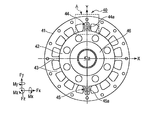
トルクセンサ40は、第1構造体41と、第2構造体42と、複数の第3構造体43と、センサ部としての第1歪センサ44及び第2歪センサ45などを具備している。
第1構造体41と、第2構造体42は、環状に形成され、第2構造体42の径は、第1構造体41の径より小さい。第2構造体42は、第1構造体41と同心状に配置され、第1構造体41と第2構造体42は、放射状に配置された複数の梁部としての第3構造体43により連結されている。複数の第3構造体43は、第1構造体41と第2構造体42との間でトルクを伝達する。第2構造体42は、中空部42aを有しており、中空部42aには、例えば図示せぬ配線が通される。
トルクセンサ40が取り付けられる第1アーム32などは、例えばアルミニウムにより構成される。このため、第1構造体41、第2構造体42、複数の第3構造体43は、アルミニウムよりヤング率が高い金属材料、例えばステンレス鋼により構成されるが、印加されるトルクや曲げモーメントに対して機械的に十分な強度を得ることができれば、金属以外の材料を使用することも可能である。
第1構造体41と第2構造体42との間には、第1歪センサ44と第2歪センサ45が設けられる。第1歪センサ44を構成する起歪体44aと、第2歪センサ45を構成する起歪体45aの一端部は、それぞれ第1構造体41に接合され、起歪体44a、45aの他端部は、それぞれ第2構造体42に接合される。
起歪体44a及び起歪体45aの厚みは、第1構造体41、第2構造体42、及び複数の第3構造体43の厚みより薄い。
第1歪センサ44と第2歪センサ45は、第1構造体41及び第2構造体42の中心(トルクの作用中心)に対して対称な位置に配置されている。換言すると、第1歪センサ44と第2歪センサ45は、環状の第1構造体41及び第2構造体42の直径上に配置されている。
起歪体44a及び起歪体45aの表面には、後述する複数の歪ゲージが設けられている。起歪体44a及び起歪体45aの各歪ゲージはそれぞれブリッジ回路を構成する。起歪体44a及び起歪体45aは、それぞれ図示せぬフレキシブル基板に接続されている。フレキシブル基板は、カバー46により覆われた図示せぬプリント基板に接続されている。プリント基板には、2つのブリッジ回路の出力電圧を増幅する演算増幅器などが配置されている。回路構成は、本実施形態の本質ではないため、説明は省略する。
図4は、図2に示す領域Aを拡大して示している。起歪体44aの表面には、センサ素子としての例えば4つの歪ゲージ51、52、53、54が設けられている。4つの歪ゲージ51、52、53、54によりブリッジ回路が構成される。
第1実施形態において、歪ゲージ51、52、53、54は、起歪体44aの有効長(起歪体として作用する部分の長さ)Lの中央部CTより、例えば第2構造体42側の領域AR1に配置されている。この領域AR1は、起歪体44aの有効長Lの範囲内で、起歪体44aに大きな歪が生じる領域であり、トルク以外の方向、例えばFx、My方向の力に対する第1歪センサ44の感度と、トルク(Mz)方向における第1歪センサ44の感度が同一となる領域である。
以下、第1構造体41及び第2構造体42において、歪ゲージ51、52、53、54に近い側を検出側と言う。第1実施形態の場合、第2構造体42が検出側に相当する。
第2歪センサ45も第1歪センサ44と同一の構成とされており、第2歪センサ45においても第2構造体42が検出側に相当する。
第1の実施形態において、トルクセンサ40の検出側の構造体の剛性は、それ以外の構造体の剛性よりも高くされている。つまり、トルクセンサ40において、第2構造体42の剛性は、第1構造体41及び第3構造体43の剛性より高くされている。
具体的には、図3に示すように、第1構造体41及び第3構造体43の厚みT1より第2構造体42の厚みT2が厚くされている。
上記構成のトルクセンサ40の第1構造体41は、例えば第1アーム32が取り付けられ、第2構造体42は、図示せぬモータや減速機を含む第1駆動部36を介して基台31に固定される。しかし、トルクセンサ40の第1構造体41を、第1駆動部36を介して基台31に固定し、第2構造体42を例えば第1アーム32に固定することも可能である。
この状態において、第1駆動部36が駆動されると、図2に示すトルク(Mz)方向の力がトルクセンサ40に印加される。トルクセンサ40の第1構造体41は、第2構造体42に対してトルク(Mz)方向に変位する。トルクセンサ40は、第1構造体41が第2構造体42に対して変位することにより、第1歪センサ44、第2歪センサ45から電気信号が出力され、トルクを検出することができる。
一方、第1アーム32乃至第4アーム35の動作により、第1アーム32にトルク以外(Mx、My)方向の曲げモーメントが発生した場合、曲げモーメントや並進力は、第1構造体41に印加される。しかし、第2構造体42は第1構造体41及び第3構造体に比べて高い剛性を有しているため、第2構造体42の変形が抑制される。このため、第1歪センサ44、第2歪センサ45を構成する複数の歪ゲージの抵抗値の変化を抑制できる。したがって、トルク以外(Mx、My)方向の曲げモーメントに対する信号の出力を抑制でき、トルクの検出精度を向上させることが可能である。
第1実施形態において、第2構造体42の剛性を高めるため、第2構造体42の厚みを第1構造体41及び第3構造体43の厚みより厚くした。しかし、これに限らず、第2構造体42を第1構造体41及び第3構造体43よりヤング率の高い材料で構成することも可能である。この場合、第2構造体42は、第1構造体41及び第3構造体43より厚い必要はなく、第1構造体41及び第3構造体43の厚み以下であってもよい。
(第1実施形態の効果)
上記第1実施形態によれば、第1歪センサ44及び第2歪センサ45を構成する歪ゲージ51、52、53、54は、起歪体44aの有効長より第2構造体42側の領域に配され、歪ゲージ51、52、53、54に近い第2構造体42は、第1構造体41及び第3構造体43より高い剛性を有している。このため、第1構造体41にトルク以外の曲げモーメントや並進力が印加された場合において、第2構造体42の変形を抑制することができるため、第1歪センサ44、第2歪センサ45を構成する複数の歪ゲージの抵抗値の変化を抑制できる。したがって、トルク以外の曲げモーメントに対する信号の出力を抑制でき、トルクの検出精度を向上させることが可能である。
上記第1実施形態によれば、第1歪センサ44及び第2歪センサ45を構成する歪ゲージ51、52、53、54は、起歪体44aの有効長より第2構造体42側の領域に配され、歪ゲージ51、52、53、54に近い第2構造体42は、第1構造体41及び第3構造体43より高い剛性を有している。このため、第1構造体41にトルク以外の曲げモーメントや並進力が印加された場合において、第2構造体42の変形を抑制することができるため、第1歪センサ44、第2歪センサ45を構成する複数の歪ゲージの抵抗値の変化を抑制できる。したがって、トルク以外の曲げモーメントに対する信号の出力を抑制でき、トルクの検出精度を向上させることが可能である。
また、トルクセンサ40の剛性を高めるため、トルクセンサ40の全体の厚みを厚くせず、検出側の第2構造体42の厚みのみを厚くしている。このため、トルクセンサ40の全体の厚みを厚くする場合に比べて、必要な性能を得るために、トルクセンサ40の軽量化が可能である。
さらに、トルクセンサ40の全体の厚みを厚くせず、第2構造体42の厚みのみを厚くしているため、トルクセンサ40が取り付けられる第1駆動部36の厚みの増加を防止することが可能である。
(第2実施形態)
図5、図6は、第2実施形態を示している。第1実施形態において、第2構造体42の剛性を第1構造体41及び第3構造体43の剛性より高くするため、第2構造体42の厚みを第1構造体41及び第3構造体43の厚みより厚くした。
図5、図6は、第2実施形態を示している。第1実施形態において、第2構造体42の剛性を第1構造体41及び第3構造体43の剛性より高くするため、第2構造体42の厚みを第1構造体41及び第3構造体43の厚みより厚くした。
一方、第2実施形態において、トルクセンサ40の第1構造体41、第2構造体42、及び第3構造体43の厚みは、図6に示すように等しく、第2構造体42の剛性を第1構造体41及び第3構造体43の剛性より高くするため、第2構造体42に補強部材としてのアダプタ60が取り付けられる。具体的には、リング状のアダプタ60は、例えば複数のネジ61により第2構造体42の一方の面に固定される。
アダプタ60の材料は、トルクセンサ40の材料と同じか、トルクセンサ40の材料よりヤング率の高い材料が適用される。
図5、図6に示すように、トルクセンサ40に複数のネジ61によりアダプタ60が取り付けられた状態において、例えばY軸を中心として左右対称に回転モーメントMyがトルクセンサ40に印加された場合、ネジ61による締結部にねじれが生じ難い方が、他軸干渉の影響を低減できる。
第2実施形態において、ネジ61は、第1歪センサ44及び第2歪センサ45を結ぶ径(Y軸)上から離れた位置に配置された場合を示している。具体的には、2つのネジ61は、第1歪センサ44及び第2歪センサ45を結ぶ径(Y軸)に対して、例えば対称の位置に配置される。
図7は、第1歪センサ44の近傍に配置された2つのネジ61と起歪体44aの位置関係を示している。2つのネジ61は、起歪体44a(Y軸)を中心として対称な位置に配置されている。
このように、2つのネジ61を第1歪センサ44に対して対称な位置に配置した場合、第1歪センサ44に対応する部分がアダプタ60により厚みが増すため、第1歪センサ44近傍の二次極モーメントが大きくなり、ねじれ難くなる。このため、Y軸を中心として回転モーメントMyがトルクセンサ40に印加された場合、2つのネジ61の間に位置する締結部62に生じるねじれを低減でき、他軸干渉の影響を低減できる。
図5は、2つのネジ61を第1歪センサ44に対して対称な位置に配置した場合であるが、ネジ61は第1歪センサ44及び第2歪センサ45を結ぶ線上に配置しても良い。しかし、ネジ61を第1歪センサ44及び第2歪センサ45を結ぶ線上以外の位置に配置することにより、2次極モーメントを大きくすることができ、よりねじれ難くなる。
(第2実施形態の効果)
上記第2実施形態によっても第1実施形態と同様に、他軸干渉を低減でき、トルクの検出精度を向上させることが可能である。
上記第2実施形態によっても第1実施形態と同様に、他軸干渉を低減でき、トルクの検出精度を向上させることが可能である。
しかも、第2実施形態によれば、トルクセンサ40とは別のアダプタ60を用いている。このため、使用条件によりアダプタ60の剛性を調整することが容易である。使用条件に合った最適な剛性を容易に設定することが可能である。
また、アダプタ60の材料として、トルクセンサ40の材料と別の材料を用いることにより、必要な剛性を得るためにアダプタ60の厚みを薄くすることができる。このため、トルクセンサ40を一層薄型化することが可能である。
さらに、トルクセンサ40とは別のアダプタ60を用いることにより、第1実施形態に比べてトルクセンサ40を加工するための工数を削減することが可能である。
アダプタ60の形状は、トルクセンサ40と同様に環状であるため、加工が容易であるため、加工工数を削減でき、製造コストの増加を抑制することが可能である。
また、アダプタ60を第2構造体42に固定するための複数のネジ61を第1歪センサ44、第2歪センサ45に対してそれぞれ対称的に配置している。このため、Y軸を中心として回転モーメントMyがトルクセンサ40に印加された場合、第1歪センサ44及び第2歪センサ45にそれぞれ対応する2つのネジ61の間に位置する締結部62に生じるねじれを低減できる。したがって、他軸干渉の影響を低減でき、トルクの検出精度を向上させることが可能である。
図8は、トルクセンサ40にアダプタ60を取り付けた状態において、Y軸を中心として左右対称に回転モーメント(入力モーメント)Myがトルクセンサ40に印加された場合における歪ゲージ51、52、53,54の抵抗の変化率を示している。
ここで、R1、R2、R3、R4は、それぞれ歪ゲージ51、52、53,54の抵抗を示している。
回転モーメントに対する抵抗の変化はヒステリシスを有するため、図8は、トルクセンサ40に2回回転モーメント印加した結果を示している。
図9は、図8の比較例を示すものであり、トルクセンサ40からアダプタ60を外した場合における抵抗の変化率を示している。
図8から明らかなように、アダプタ60をトルクセンサ40に取り付けることにより、回転モーメントMyの影響(他軸干渉)が低減され、抵抗値の変化が抑制されていることが分かる。
図10は、アダプタ60の厚みを変えた場合における抵抗の変化率を示している。図9に示すアダプタ60が無い場合の抵抗の変化率の幅Wを100%として記し、アダプタ60の厚みが、例えば5mm及び10mmにおける抵抗の変化率の平均値をそれぞれ記している。ここで、Nは、アダプタ60が無い場合を示している。
図10から明らかなように、アダプタ60が無い場合(N)からアダプタ60の厚みが5mm、10mmと増加するに従い、他軸干渉の影響が低減されることが分かる。すなわち、アダプタ60の剛性が高まるに従って、他軸干渉の影響が低減されることが分かる。
(第3実施形態)
図11は、第3実施形態を示している。
図11は、第3実施形態を示している。
第1実施形態及び第2実施形態において、歪ゲージ51、52、53、54が配置される領域AR1は、第2構造体42の近傍であり、第2構造体42が検出側に相当していた。このため、第2構造体42の剛性を第1構造体41及び第3構造体43の剛性より高くした。
第3実施形態において、歪ゲージ51、52、53、54が配置される領域は、図11に示すように、第1構造体41の近傍であり、第1構造体41が検出側に相当する。
図示せぬ第2歪センサ45の歪ゲージも、第1歪センサ44の歪ゲージと同様に第1構造体41の近傍に配置される。
このため、検出側としての第1構造体41の剛性が、第2構造体42及び第3構造体43の剛性より高くされる。
具体的には、第1構造体41の厚みが第2構造体42、第3構造体43の厚みより厚くされる。
第1構造体41の剛性を高める手段としては、第1実施形態と同様に、第1構造体41の材料をヤング率の高い材料で形成することが可能である。
又は、図12に示すように、第2実施形態と同様に、第1構造体41の一方の面に補強部材としてのリング状のアダプタ70を複数のネジ71により取り付けることも可能である。この場合、第1構造体41、第2構造体42、及び第3構造体43の厚みは、等しい。
また、2つのネジ71を第1歪センサ44に対して対称となる位置に配置した場合、第1歪センサ44に対応する部分の厚みが増すため、二次極モーメントが大きくなり、締結部がねじれ難くなる。このため、Y軸を中心として回転モーメントMyがトルクセンサ40に印加された場合、2つのネジ71の間に位置する締結部に生じるねじれを低減でき、他軸干渉の影響を低減できる。
ネジ71は第1歪センサ44及び第2歪センサ45を結ぶ線上に配置しても良い。しかし、ネジ71を第1歪センサ44及び第2歪センサ45を結ぶ線上以外の位置に配置することにより、2次極モーメントを大きくすることができ、よりねじれ難くなる。
(第3実施形態の効果)
上記第3実施形態によっても第1実施形態及び第2実施形態と同様の効果を得ることが可能である。
上記第3実施形態によっても第1実施形態及び第2実施形態と同様の効果を得ることが可能である。
その他、本発明は上記各実施形態そのままに限定されるものではなく、実施段階ではその要旨を逸脱しない範囲で構成要素を変形して具体化できる。また、上記各実施形態に開示されている複数の構成要素の適宜な組み合わせにより、種々の発明を形成できる。例えば、実施形態に示される全構成要素から幾つかの構成要素を削除してもよい。さらに、異なる実施形態にわたる構成要素を適宜組み合わせてもよい。
Claims (14)
- 第1構造体と、
第2構造体と、
前記第1構造体と前記第2構造体との間に設けられた第3構造体と、
前記第1構造体と前記第2構造体との間に設けられた少なくとも2つのセンサ部と、
を具備し、
前記センサ部に近い前記第1構造体と前記第2構造体の一方の剛性は、前記センサ部から遠い前記第1構造体と前記第2構造体の他方より高いことを特徴とするトルクセンサ。 - 前記センサ部は、前記第2構造体の近傍に配置されることを特徴とする請求項1記載のトルクセンサ。
- 前記第2構造体の厚みは、前記第1構造体及び前記第3構造体の厚みより厚いことを特徴とする請求項2記載のトルクセンサ。
- 前記第2構造体は、前記第1構造体及び前記第3構造体よりヤング率の高い材料により構成されることを特徴とする請求項2記載のトルクセンサ。
- 前記第2構造体は、補強部材をさらに具備することを特徴とする請求項2記載のトルクセンサ。
- 前記第1構造体、前記第2構造体、及び前記第3構造体の厚みは等しいことを特徴とする請求項5記載のトルクセンサ。
- 前記補強部材を前記第2構造体に固定するネジをさらに具備し、前記ネジは、前記2つのセンサ部を結ぶ線に対し、対称となる位置に設けられることを特徴とする請求項5記載のトルクセンサ。
- 前記補強部材を前記第2構造体に固定するネジをさらに具備し、前記ネジは、前記2つのセンサ部を結ぶ線上以外の位置に設けられることを特徴とする請求項5記載のトルクセンサ。
- 前記センサ部は、前記第1構造体の近傍に配置されることを特徴とする請求項1記載のトルクセンサ。
- 前記第1構造体の厚みは、前記第2構造体及び前記第3構造体の厚みより厚いことを特徴とする請求項9記載のトルクセンサ。
- 前記第1構造体は、補強部材をさらに具備することを特徴とする請求項9記載のトルクセンサ。
- 前記第1構造体、前記第2構造体、及び前記第3構造体の厚みは等しいことを特徴とする請求項11記載のトルクセンサ。
- 前記補強部材を前記第1構造体に固定するネジをさらに具備し、前記ネジは、前記2つのセンサ部を結ぶ線に対し、対称的となる位置に設けられることを特徴とする請求項11記載のトルクセンサ。
- 前記補強部材を前記第1構造体に固定するネジをさらに具備し、前記ネジは、前記2つのセンサ部を結ぶ線上以外の位置に設けられることを特徴とする請求項11記載のトルクセンサ。
Priority Applications (3)
| Application Number | Priority Date | Filing Date | Title |
|---|---|---|---|
| EP19833689.3A EP3822603A4 (en) | 2018-07-13 | 2019-04-26 | TORQUE SENSOR |
| CN201980046901.5A CN112424578B (zh) | 2018-07-13 | 2019-04-26 | 扭矩传感器 |
| US17/147,146 US11781927B2 (en) | 2018-07-13 | 2021-01-12 | Torque sensor |
Applications Claiming Priority (2)
| Application Number | Priority Date | Filing Date | Title |
|---|---|---|---|
| JP2018-133260 | 2018-07-13 | ||
| JP2018133260A JP2020012660A (ja) | 2018-07-13 | 2018-07-13 | トルクセンサ |
Related Child Applications (1)
| Application Number | Title | Priority Date | Filing Date |
|---|---|---|---|
| US17/147,146 Continuation US11781927B2 (en) | 2018-07-13 | 2021-01-12 | Torque sensor |
Publications (1)
| Publication Number | Publication Date |
|---|---|
| WO2020012764A1 true WO2020012764A1 (ja) | 2020-01-16 |
Family
ID=69142921
Family Applications (1)
| Application Number | Title | Priority Date | Filing Date |
|---|---|---|---|
| PCT/JP2019/018146 Ceased WO2020012764A1 (ja) | 2018-07-13 | 2019-04-26 | トルクセンサ |
Country Status (6)
| Country | Link |
|---|---|
| US (1) | US11781927B2 (ja) |
| EP (1) | EP3822603A4 (ja) |
| JP (1) | JP2020012660A (ja) |
| CN (1) | CN112424578B (ja) |
| TW (1) | TWI818989B (ja) |
| WO (1) | WO2020012764A1 (ja) |
Families Citing this family (6)
| Publication number | Priority date | Publication date | Assignee | Title |
|---|---|---|---|---|
| US12214488B2 (en) * | 2019-09-03 | 2025-02-04 | Shanghai Flexiv Robotics Technology Co., Ltd. | Robotic arm and robot |
| JP2022073177A (ja) * | 2020-10-30 | 2022-05-17 | 多摩川精機株式会社 | トルクセンサ、トルクセンサ製造方法、および耐荷重設計用トルクセンサ部品組 |
| JP7586716B2 (ja) * | 2021-01-12 | 2024-11-19 | ミネベアミツミ株式会社 | ドライブプレート型トルク変換器 |
| AU2022218950A1 (en) * | 2021-02-11 | 2023-08-31 | Mako Surgical Corp. | Robotic manipulator comprising isolation mechanism for force/torque sensor |
| EP4174465A1 (en) | 2021-10-27 | 2023-05-03 | Canon Kabushiki Kaisha | Sensor, device, system, and manufacturing method for product |
| JP2024072155A (ja) * | 2022-11-15 | 2024-05-27 | 新東工業株式会社 | トルクセンサおよびロボット |
Citations (9)
| Publication number | Priority date | Publication date | Assignee | Title |
|---|---|---|---|---|
| JPH05187940A (ja) | 1992-01-14 | 1993-07-27 | Fujitsu Ltd | 力検出装置とその方法 |
| JP2010169586A (ja) | 2009-01-23 | 2010-08-05 | Minebea Co Ltd | トルク量変換器 |
| JP2013096735A (ja) | 2011-10-28 | 2013-05-20 | Toyota Motor Corp | 起歪体及びトルクセンサ |
| WO2014156823A1 (ja) * | 2013-03-27 | 2014-10-02 | Semitec株式会社 | 接触力センサ及びその製造方法 |
| JP2015049209A (ja) | 2013-09-04 | 2015-03-16 | トヨタ自動車株式会社 | トルクセンサ |
| US20170205296A1 (en) | 2016-01-19 | 2017-07-20 | Ati Industrial Automation, Inc. | Force/torque sensor having instrumentation on fewer than four beam surfaces |
| EP3219449A2 (en) | 2016-03-18 | 2017-09-20 | Kabushiki Kaisha Yaskawa Denki | Robot and torque sensor |
| JP2017203645A (ja) * | 2016-05-09 | 2017-11-16 | ソニー株式会社 | トルクセンサ及び力制御型アクチュエータ |
| WO2018041974A1 (de) * | 2016-08-31 | 2018-03-08 | Sensodrive Gmbh | Drehmomentsensor mit nebenschlussspeiche |
Family Cites Families (24)
| Publication number | Priority date | Publication date | Assignee | Title |
|---|---|---|---|---|
| US4836034A (en) * | 1986-07-15 | 1989-06-06 | Ricoh Company, Ltd. | Force sensing apparatus |
| KR100199691B1 (ko) * | 1997-05-19 | 1999-06-15 | 김동진 | 6분력 로드셀 |
| US6038933A (en) * | 1997-07-15 | 2000-03-21 | Mts Systems Corporation | Multi-axis load cell |
| JP3261653B2 (ja) * | 1999-07-07 | 2002-03-04 | 独立行政法人産業技術総合研究所 | 指装着型6軸力覚センサ |
| EP1491854A4 (en) * | 2002-04-02 | 2006-11-02 | Asahi Kasei Emd Corp | INCLINATION SENSOR, METHOD FOR MANUFACTURING THE INCLINATION SENSOR, AND METHOD FOR MEASURING THE INCLINATION |
| WO2005085981A1 (en) * | 2004-02-03 | 2005-09-15 | Nokia Corporation | Method and device for implementing vibration output commands in mobile terminal devices |
| JP5243704B2 (ja) * | 2006-08-24 | 2013-07-24 | 本田技研工業株式会社 | 力覚センサ |
| JP5243988B2 (ja) * | 2009-02-10 | 2013-07-24 | 本田技研工業株式会社 | 多軸力覚センサおよび加速度センサ |
| JP5719521B2 (ja) * | 2010-03-30 | 2015-05-20 | ミネベア株式会社 | 3軸力センサ |
| JP5507306B2 (ja) * | 2010-03-30 | 2014-05-28 | 本田技研工業株式会社 | 力覚センサ用チップおよび加速度センサ用チップ |
| JP4948630B2 (ja) * | 2010-08-05 | 2012-06-06 | 株式会社トライフォース・マネジメント | トルクセンサ |
| US9778119B2 (en) * | 2013-10-05 | 2017-10-03 | Bertec Limited | Load transducer and force measurement assembly using the same |
| JP6047703B2 (ja) * | 2014-09-26 | 2016-12-21 | 株式会社レプトリノ | 力覚センサ |
| US10557764B2 (en) * | 2015-01-26 | 2020-02-11 | Tri-Force Management Corporation | Torque sensor which detects torque around a predetermined rotation axis |
| US10416030B2 (en) * | 2015-01-26 | 2019-09-17 | Wacoh-Tech Inc. | Force sensor |
| KR101755845B1 (ko) * | 2015-09-18 | 2017-07-07 | 현대자동차주식회사 | 부품 검사 장치 |
| WO2018029790A1 (ja) * | 2016-08-09 | 2018-02-15 | 株式会社 トライフォース・マネジメント | 力覚センサ |
| DE102016012324A1 (de) * | 2016-10-17 | 2018-04-19 | Franka Emika Gmbh | Drehmomentsensorvorrichtung und Verfahren zum Erfassen von Drehmomenten |
| JP6808469B2 (ja) * | 2016-12-07 | 2021-01-06 | 日本電産コパル電子株式会社 | トルクセンサ |
| JP6692762B2 (ja) * | 2017-02-13 | 2020-05-13 | 日本電産コパル電子株式会社 | トルクセンサ |
| JP6919964B2 (ja) * | 2018-01-29 | 2021-08-18 | ミネベアミツミ株式会社 | センサチップ及び力覚センサ装置 |
| JP7034811B2 (ja) * | 2018-04-09 | 2022-03-14 | 日本電産コパル電子株式会社 | 歪センサの固定装置とそれを用いたトルクセンサ |
| JP6999586B2 (ja) * | 2019-01-28 | 2022-01-18 | 日本電産コパル電子株式会社 | 弾性体とそれを用いた力覚センサ |
| JP7039502B2 (ja) * | 2019-01-28 | 2022-03-22 | 日本電産コパル電子株式会社 | 力覚センサ |
-
2018
- 2018-07-13 JP JP2018133260A patent/JP2020012660A/ja active Pending
-
2019
- 2019-04-26 WO PCT/JP2019/018146 patent/WO2020012764A1/ja not_active Ceased
- 2019-04-26 CN CN201980046901.5A patent/CN112424578B/zh active Active
- 2019-04-26 EP EP19833689.3A patent/EP3822603A4/en not_active Withdrawn
- 2019-05-14 TW TW108116531A patent/TWI818989B/zh active
-
2021
- 2021-01-12 US US17/147,146 patent/US11781927B2/en active Active
Patent Citations (11)
| Publication number | Priority date | Publication date | Assignee | Title |
|---|---|---|---|---|
| JPH05187940A (ja) | 1992-01-14 | 1993-07-27 | Fujitsu Ltd | 力検出装置とその方法 |
| JP2010169586A (ja) | 2009-01-23 | 2010-08-05 | Minebea Co Ltd | トルク量変換器 |
| JP2013096735A (ja) | 2011-10-28 | 2013-05-20 | Toyota Motor Corp | 起歪体及びトルクセンサ |
| WO2014156823A1 (ja) * | 2013-03-27 | 2014-10-02 | Semitec株式会社 | 接触力センサ及びその製造方法 |
| JP2015049209A (ja) | 2013-09-04 | 2015-03-16 | トヨタ自動車株式会社 | トルクセンサ |
| US20170205296A1 (en) | 2016-01-19 | 2017-07-20 | Ati Industrial Automation, Inc. | Force/torque sensor having instrumentation on fewer than four beam surfaces |
| EP3219449A2 (en) | 2016-03-18 | 2017-09-20 | Kabushiki Kaisha Yaskawa Denki | Robot and torque sensor |
| JP2017172983A (ja) | 2016-03-18 | 2017-09-28 | 株式会社安川電機 | ロボット及びトルクセンサ |
| JP2017203645A (ja) * | 2016-05-09 | 2017-11-16 | ソニー株式会社 | トルクセンサ及び力制御型アクチュエータ |
| EP3418704A1 (en) | 2016-05-09 | 2018-12-26 | Sony Corporation | Torque sensor and force-controllable actuator |
| WO2018041974A1 (de) * | 2016-08-31 | 2018-03-08 | Sensodrive Gmbh | Drehmomentsensor mit nebenschlussspeiche |
Also Published As
| Publication number | Publication date |
|---|---|
| CN112424578A (zh) | 2021-02-26 |
| TWI818989B (zh) | 2023-10-21 |
| TW202006328A (zh) | 2020-02-01 |
| EP3822603A4 (en) | 2022-05-11 |
| EP3822603A1 (en) | 2021-05-19 |
| US11781927B2 (en) | 2023-10-10 |
| JP2020012660A (ja) | 2020-01-23 |
| CN112424578B (zh) | 2023-01-03 |
| US20210131891A1 (en) | 2021-05-06 |
Similar Documents
| Publication | Publication Date | Title |
|---|---|---|
| TWI818989B (zh) | 轉矩感測器 | |
| WO2018105209A1 (ja) | トルクセンサ | |
| US11761835B2 (en) | Mounting structure for torque sensor | |
| US11781928B2 (en) | Torque sensor attachment structure | |
| JP6808469B2 (ja) | トルクセンサ | |
| CN111684250B (zh) | 扭矩传感器 | |
| TWI811360B (zh) | 轉矩感測器之支撐裝置 | |
| JP7200058B2 (ja) | トルクセンサの取り付け構造 | |
| JP7066560B2 (ja) | トルクセンサの取り付け構造 | |
| JP6999587B2 (ja) | 弾性体とそれを用いた力覚センサ | |
| JP2008096230A5 (ja) | ||
| JP7062540B2 (ja) | トルクセンサ | |
| JP6935602B2 (ja) | トルクセンサ | |
| WO2020012763A1 (ja) | トルクセンサ | |
| JP7775123B2 (ja) | トルクセンサ | |
| JPH0582535B2 (ja) | ||
| JP2006058211A (ja) | 歪みゲージ型センサ | |
| JP2025018812A (ja) | 力覚センサ | |
| JP2020012659A (ja) | トルクセンサ |
Legal Events
| Date | Code | Title | Description |
|---|---|---|---|
| 121 | Ep: the epo has been informed by wipo that ep was designated in this application |
Ref document number: 19833689 Country of ref document: EP Kind code of ref document: A1 |
|
| NENP | Non-entry into the national phase |
Ref country code: DE |
|
| ENP | Entry into the national phase |
Ref document number: 2019833689 Country of ref document: EP Effective date: 20210215 |