WO2020013251A1 - Dispositif de commande de moteur - Google Patents
Dispositif de commande de moteur Download PDFInfo
- Publication number
- WO2020013251A1 WO2020013251A1 PCT/JP2019/027417 JP2019027417W WO2020013251A1 WO 2020013251 A1 WO2020013251 A1 WO 2020013251A1 JP 2019027417 W JP2019027417 W JP 2019027417W WO 2020013251 A1 WO2020013251 A1 WO 2020013251A1
- Authority
- WO
- WIPO (PCT)
- Prior art keywords
- map
- torque
- motor
- battery
- unit
- Prior art date
- Legal status (The legal status is an assumption and is not a legal conclusion. Google has not performed a legal analysis and makes no representation as to the accuracy of the status listed.)
- Ceased
Links
Images




Classifications
-
- B—PERFORMING OPERATIONS; TRANSPORTING
- B60—VEHICLES IN GENERAL
- B60K—ARRANGEMENT OR MOUNTING OF PROPULSION UNITS OR OF TRANSMISSIONS IN VEHICLES; ARRANGEMENT OR MOUNTING OF PLURAL DIVERSE PRIME-MOVERS IN VEHICLES; AUXILIARY DRIVES FOR VEHICLES; INSTRUMENTATION OR DASHBOARDS FOR VEHICLES; ARRANGEMENTS IN CONNECTION WITH COOLING, AIR INTAKE, GAS EXHAUST OR FUEL SUPPLY OF PROPULSION UNITS IN VEHICLES
- B60K6/00—Arrangement or mounting of plural diverse prime-movers for mutual or common propulsion, e.g. hybrid propulsion systems comprising electric motors and internal combustion engines
- B60K6/20—Arrangement or mounting of plural diverse prime-movers for mutual or common propulsion, e.g. hybrid propulsion systems comprising electric motors and internal combustion engines the prime-movers consisting of electric motors and internal combustion engines, e.g. HEVs
- B60K6/22—Arrangement or mounting of plural diverse prime-movers for mutual or common propulsion, e.g. hybrid propulsion systems comprising electric motors and internal combustion engines the prime-movers consisting of electric motors and internal combustion engines, e.g. HEVs characterised by apparatus, components or means specially adapted for HEVs
- B60K6/28—Arrangement or mounting of plural diverse prime-movers for mutual or common propulsion, e.g. hybrid propulsion systems comprising electric motors and internal combustion engines the prime-movers consisting of electric motors and internal combustion engines, e.g. HEVs characterised by apparatus, components or means specially adapted for HEVs characterised by the electric energy storing means, e.g. batteries or capacitors
-
- B—PERFORMING OPERATIONS; TRANSPORTING
- B60—VEHICLES IN GENERAL
- B60W—CONJOINT CONTROL OF VEHICLE SUB-UNITS OF DIFFERENT TYPE OR DIFFERENT FUNCTION; CONTROL SYSTEMS SPECIALLY ADAPTED FOR HYBRID VEHICLES; ROAD VEHICLE DRIVE CONTROL SYSTEMS FOR PURPOSES NOT RELATED TO THE CONTROL OF A PARTICULAR SUB-UNIT
- B60W20/00—Control systems specially adapted for hybrid vehicles
- B60W20/10—Controlling the power contribution of each of the prime movers to meet required power demand
- B60W20/15—Control strategies specially adapted for achieving a particular effect
-
- B—PERFORMING OPERATIONS; TRANSPORTING
- B60—VEHICLES IN GENERAL
- B60K—ARRANGEMENT OR MOUNTING OF PROPULSION UNITS OR OF TRANSMISSIONS IN VEHICLES; ARRANGEMENT OR MOUNTING OF PLURAL DIVERSE PRIME-MOVERS IN VEHICLES; AUXILIARY DRIVES FOR VEHICLES; INSTRUMENTATION OR DASHBOARDS FOR VEHICLES; ARRANGEMENTS IN CONNECTION WITH COOLING, AIR INTAKE, GAS EXHAUST OR FUEL SUPPLY OF PROPULSION UNITS IN VEHICLES
- B60K6/00—Arrangement or mounting of plural diverse prime-movers for mutual or common propulsion, e.g. hybrid propulsion systems comprising electric motors and internal combustion engines
- B60K6/20—Arrangement or mounting of plural diverse prime-movers for mutual or common propulsion, e.g. hybrid propulsion systems comprising electric motors and internal combustion engines the prime-movers consisting of electric motors and internal combustion engines, e.g. HEVs
- B60K6/22—Arrangement or mounting of plural diverse prime-movers for mutual or common propulsion, e.g. hybrid propulsion systems comprising electric motors and internal combustion engines the prime-movers consisting of electric motors and internal combustion engines, e.g. HEVs characterised by apparatus, components or means specially adapted for HEVs
- B60K6/38—Arrangement or mounting of plural diverse prime-movers for mutual or common propulsion, e.g. hybrid propulsion systems comprising electric motors and internal combustion engines the prime-movers consisting of electric motors and internal combustion engines, e.g. HEVs characterised by apparatus, components or means specially adapted for HEVs characterised by the driveline clutches
- B60K6/387—Actuated clutches, i.e. clutches engaged or disengaged by electric, hydraulic or mechanical actuating means
-
- B—PERFORMING OPERATIONS; TRANSPORTING
- B60—VEHICLES IN GENERAL
- B60K—ARRANGEMENT OR MOUNTING OF PROPULSION UNITS OR OF TRANSMISSIONS IN VEHICLES; ARRANGEMENT OR MOUNTING OF PLURAL DIVERSE PRIME-MOVERS IN VEHICLES; AUXILIARY DRIVES FOR VEHICLES; INSTRUMENTATION OR DASHBOARDS FOR VEHICLES; ARRANGEMENTS IN CONNECTION WITH COOLING, AIR INTAKE, GAS EXHAUST OR FUEL SUPPLY OF PROPULSION UNITS IN VEHICLES
- B60K6/00—Arrangement or mounting of plural diverse prime-movers for mutual or common propulsion, e.g. hybrid propulsion systems comprising electric motors and internal combustion engines
- B60K6/20—Arrangement or mounting of plural diverse prime-movers for mutual or common propulsion, e.g. hybrid propulsion systems comprising electric motors and internal combustion engines the prime-movers consisting of electric motors and internal combustion engines, e.g. HEVs
- B60K6/42—Arrangement or mounting of plural diverse prime-movers for mutual or common propulsion, e.g. hybrid propulsion systems comprising electric motors and internal combustion engines the prime-movers consisting of electric motors and internal combustion engines, e.g. HEVs characterised by the architecture of the hybrid electric vehicle
- B60K6/48—Parallel type
-
- B—PERFORMING OPERATIONS; TRANSPORTING
- B60—VEHICLES IN GENERAL
- B60L—PROPULSION OF ELECTRICALLY-PROPELLED VEHICLES; SUPPLYING ELECTRIC POWER FOR AUXILIARY EQUIPMENT OF ELECTRICALLY-PROPELLED VEHICLES; ELECTRODYNAMIC BRAKE SYSTEMS FOR VEHICLES IN GENERAL; MAGNETIC SUSPENSION OR LEVITATION FOR VEHICLES; MONITORING OPERATING VARIABLES OF ELECTRICALLY-PROPELLED VEHICLES; ELECTRIC SAFETY DEVICES FOR ELECTRICALLY-PROPELLED VEHICLES
- B60L15/00—Methods, circuits, or devices for controlling the traction-motor speed of electrically-propelled vehicles
- B60L15/20—Methods, circuits, or devices for controlling the traction-motor speed of electrically-propelled vehicles for control of the vehicle or its driving motor to achieve a desired performance, e.g. speed, torque, programmed variation of speed
- B60L15/2045—Methods, circuits, or devices for controlling the traction-motor speed of electrically-propelled vehicles for control of the vehicle or its driving motor to achieve a desired performance, e.g. speed, torque, programmed variation of speed for optimising the use of energy
-
- B—PERFORMING OPERATIONS; TRANSPORTING
- B60—VEHICLES IN GENERAL
- B60L—PROPULSION OF ELECTRICALLY-PROPELLED VEHICLES; SUPPLYING ELECTRIC POWER FOR AUXILIARY EQUIPMENT OF ELECTRICALLY-PROPELLED VEHICLES; ELECTRODYNAMIC BRAKE SYSTEMS FOR VEHICLES IN GENERAL; MAGNETIC SUSPENSION OR LEVITATION FOR VEHICLES; MONITORING OPERATING VARIABLES OF ELECTRICALLY-PROPELLED VEHICLES; ELECTRIC SAFETY DEVICES FOR ELECTRICALLY-PROPELLED VEHICLES
- B60L50/00—Electric propulsion with power supplied within the vehicle
- B60L50/50—Electric propulsion with power supplied within the vehicle using propulsion power supplied by batteries or fuel cells
- B60L50/60—Electric propulsion with power supplied within the vehicle using propulsion power supplied by batteries or fuel cells using power supplied by batteries
- B60L50/61—Electric propulsion with power supplied within the vehicle using propulsion power supplied by batteries or fuel cells using power supplied by batteries by batteries charged by engine-driven generators, e.g. series hybrid electric vehicles
-
- B—PERFORMING OPERATIONS; TRANSPORTING
- B60—VEHICLES IN GENERAL
- B60L—PROPULSION OF ELECTRICALLY-PROPELLED VEHICLES; SUPPLYING ELECTRIC POWER FOR AUXILIARY EQUIPMENT OF ELECTRICALLY-PROPELLED VEHICLES; ELECTRODYNAMIC BRAKE SYSTEMS FOR VEHICLES IN GENERAL; MAGNETIC SUSPENSION OR LEVITATION FOR VEHICLES; MONITORING OPERATING VARIABLES OF ELECTRICALLY-PROPELLED VEHICLES; ELECTRIC SAFETY DEVICES FOR ELECTRICALLY-PROPELLED VEHICLES
- B60L58/00—Methods or circuit arrangements for monitoring or controlling batteries or fuel cells, specially adapted for electric vehicles
- B60L58/10—Methods or circuit arrangements for monitoring or controlling batteries or fuel cells, specially adapted for electric vehicles for monitoring or controlling batteries
- B60L58/12—Methods or circuit arrangements for monitoring or controlling batteries or fuel cells, specially adapted for electric vehicles for monitoring or controlling batteries responding to state of charge [SoC]
-
- B—PERFORMING OPERATIONS; TRANSPORTING
- B60—VEHICLES IN GENERAL
- B60L—PROPULSION OF ELECTRICALLY-PROPELLED VEHICLES; SUPPLYING ELECTRIC POWER FOR AUXILIARY EQUIPMENT OF ELECTRICALLY-PROPELLED VEHICLES; ELECTRODYNAMIC BRAKE SYSTEMS FOR VEHICLES IN GENERAL; MAGNETIC SUSPENSION OR LEVITATION FOR VEHICLES; MONITORING OPERATING VARIABLES OF ELECTRICALLY-PROPELLED VEHICLES; ELECTRIC SAFETY DEVICES FOR ELECTRICALLY-PROPELLED VEHICLES
- B60L58/00—Methods or circuit arrangements for monitoring or controlling batteries or fuel cells, specially adapted for electric vehicles
- B60L58/10—Methods or circuit arrangements for monitoring or controlling batteries or fuel cells, specially adapted for electric vehicles for monitoring or controlling batteries
- B60L58/24—Methods or circuit arrangements for monitoring or controlling batteries or fuel cells, specially adapted for electric vehicles for monitoring or controlling batteries for controlling the temperature of batteries
- B60L58/25—Methods or circuit arrangements for monitoring or controlling batteries or fuel cells, specially adapted for electric vehicles for monitoring or controlling batteries for controlling the temperature of batteries by controlling the electric load
-
- B—PERFORMING OPERATIONS; TRANSPORTING
- B60—VEHICLES IN GENERAL
- B60W—CONJOINT CONTROL OF VEHICLE SUB-UNITS OF DIFFERENT TYPE OR DIFFERENT FUNCTION; CONTROL SYSTEMS SPECIALLY ADAPTED FOR HYBRID VEHICLES; ROAD VEHICLE DRIVE CONTROL SYSTEMS FOR PURPOSES NOT RELATED TO THE CONTROL OF A PARTICULAR SUB-UNIT
- B60W10/00—Conjoint control of vehicle sub-units of different type or different function
- B60W10/04—Conjoint control of vehicle sub-units of different type or different function including control of propulsion units
- B60W10/08—Conjoint control of vehicle sub-units of different type or different function including control of propulsion units including control of electric propulsion units, e.g. motors or generators
-
- B—PERFORMING OPERATIONS; TRANSPORTING
- B60—VEHICLES IN GENERAL
- B60W—CONJOINT CONTROL OF VEHICLE SUB-UNITS OF DIFFERENT TYPE OR DIFFERENT FUNCTION; CONTROL SYSTEMS SPECIALLY ADAPTED FOR HYBRID VEHICLES; ROAD VEHICLE DRIVE CONTROL SYSTEMS FOR PURPOSES NOT RELATED TO THE CONTROL OF A PARTICULAR SUB-UNIT
- B60W10/00—Conjoint control of vehicle sub-units of different type or different function
- B60W10/24—Conjoint control of vehicle sub-units of different type or different function including control of energy storage means
- B60W10/26—Conjoint control of vehicle sub-units of different type or different function including control of energy storage means for electrical energy, e.g. batteries or capacitors
-
- B—PERFORMING OPERATIONS; TRANSPORTING
- B60—VEHICLES IN GENERAL
- B60W—CONJOINT CONTROL OF VEHICLE SUB-UNITS OF DIFFERENT TYPE OR DIFFERENT FUNCTION; CONTROL SYSTEMS SPECIALLY ADAPTED FOR HYBRID VEHICLES; ROAD VEHICLE DRIVE CONTROL SYSTEMS FOR PURPOSES NOT RELATED TO THE CONTROL OF A PARTICULAR SUB-UNIT
- B60W20/00—Control systems specially adapted for hybrid vehicles
- B60W20/10—Controlling the power contribution of each of the prime movers to meet required power demand
-
- B—PERFORMING OPERATIONS; TRANSPORTING
- B60—VEHICLES IN GENERAL
- B60W—CONJOINT CONTROL OF VEHICLE SUB-UNITS OF DIFFERENT TYPE OR DIFFERENT FUNCTION; CONTROL SYSTEMS SPECIALLY ADAPTED FOR HYBRID VEHICLES; ROAD VEHICLE DRIVE CONTROL SYSTEMS FOR PURPOSES NOT RELATED TO THE CONTROL OF A PARTICULAR SUB-UNIT
- B60W20/00—Control systems specially adapted for hybrid vehicles
- B60W20/10—Controlling the power contribution of each of the prime movers to meet required power demand
- B60W20/11—Controlling the power contribution of each of the prime movers to meet required power demand using model predictive control [MPC] strategies, i.e. control methods based on models predicting performance
-
- B—PERFORMING OPERATIONS; TRANSPORTING
- B60—VEHICLES IN GENERAL
- B60W—CONJOINT CONTROL OF VEHICLE SUB-UNITS OF DIFFERENT TYPE OR DIFFERENT FUNCTION; CONTROL SYSTEMS SPECIALLY ADAPTED FOR HYBRID VEHICLES; ROAD VEHICLE DRIVE CONTROL SYSTEMS FOR PURPOSES NOT RELATED TO THE CONTROL OF A PARTICULAR SUB-UNIT
- B60W20/00—Control systems specially adapted for hybrid vehicles
- B60W20/10—Controlling the power contribution of each of the prime movers to meet required power demand
- B60W20/13—Controlling the power contribution of each of the prime movers to meet required power demand in order to stay within battery power input or output limits; in order to prevent overcharging or battery depletion
-
- B—PERFORMING OPERATIONS; TRANSPORTING
- B60—VEHICLES IN GENERAL
- B60W—CONJOINT CONTROL OF VEHICLE SUB-UNITS OF DIFFERENT TYPE OR DIFFERENT FUNCTION; CONTROL SYSTEMS SPECIALLY ADAPTED FOR HYBRID VEHICLES; ROAD VEHICLE DRIVE CONTROL SYSTEMS FOR PURPOSES NOT RELATED TO THE CONTROL OF A PARTICULAR SUB-UNIT
- B60W50/00—Details of control systems for road vehicle drive control not related to the control of a particular sub-unit, e.g. process diagnostic or vehicle driver interfaces
- B60W50/04—Monitoring the functioning of the control system
- B60W50/045—Monitoring control system parameters
-
- G—PHYSICS
- G06—COMPUTING OR CALCULATING; COUNTING
- G06N—COMPUTING ARRANGEMENTS BASED ON SPECIFIC COMPUTATIONAL MODELS
- G06N3/00—Computing arrangements based on biological models
- G06N3/02—Neural networks
- G06N3/04—Architecture, e.g. interconnection topology
- G06N3/0499—Feedforward networks
-
- G—PHYSICS
- G06—COMPUTING OR CALCULATING; COUNTING
- G06N—COMPUTING ARRANGEMENTS BASED ON SPECIFIC COMPUTATIONAL MODELS
- G06N3/00—Computing arrangements based on biological models
- G06N3/02—Neural networks
- G06N3/08—Learning methods
- G06N3/09—Supervised learning
-
- H—ELECTRICITY
- H01—ELECTRIC ELEMENTS
- H01M—PROCESSES OR MEANS, e.g. BATTERIES, FOR THE DIRECT CONVERSION OF CHEMICAL ENERGY INTO ELECTRICAL ENERGY
- H01M10/00—Secondary cells; Manufacture thereof
- H01M10/42—Methods or arrangements for servicing or maintenance of secondary cells or secondary half-cells
- H01M10/425—Structural combination with electronic components, e.g. electronic circuits integrated to the outside of the casing
- H01M10/4257—Smart batteries, e.g. electronic circuits inside the housing of the cells or batteries
-
- H—ELECTRICITY
- H01—ELECTRIC ELEMENTS
- H01M—PROCESSES OR MEANS, e.g. BATTERIES, FOR THE DIRECT CONVERSION OF CHEMICAL ENERGY INTO ELECTRICAL ENERGY
- H01M10/00—Secondary cells; Manufacture thereof
- H01M10/42—Methods or arrangements for servicing or maintenance of secondary cells or secondary half-cells
- H01M10/46—Accumulators structurally combined with charging apparatus
-
- H—ELECTRICITY
- H01—ELECTRIC ELEMENTS
- H01M—PROCESSES OR MEANS, e.g. BATTERIES, FOR THE DIRECT CONVERSION OF CHEMICAL ENERGY INTO ELECTRICAL ENERGY
- H01M10/00—Secondary cells; Manufacture thereof
- H01M10/42—Methods or arrangements for servicing or maintenance of secondary cells or secondary half-cells
- H01M10/48—Accumulators combined with arrangements for measuring, testing or indicating the condition of cells, e.g. the level or density of the electrolyte
-
- H—ELECTRICITY
- H01—ELECTRIC ELEMENTS
- H01M—PROCESSES OR MEANS, e.g. BATTERIES, FOR THE DIRECT CONVERSION OF CHEMICAL ENERGY INTO ELECTRICAL ENERGY
- H01M10/00—Secondary cells; Manufacture thereof
- H01M10/42—Methods or arrangements for servicing or maintenance of secondary cells or secondary half-cells
- H01M10/48—Accumulators combined with arrangements for measuring, testing or indicating the condition of cells, e.g. the level or density of the electrolyte
- H01M10/486—Accumulators combined with arrangements for measuring, testing or indicating the condition of cells, e.g. the level or density of the electrolyte for measuring temperature
-
- B—PERFORMING OPERATIONS; TRANSPORTING
- B60—VEHICLES IN GENERAL
- B60K—ARRANGEMENT OR MOUNTING OF PROPULSION UNITS OR OF TRANSMISSIONS IN VEHICLES; ARRANGEMENT OR MOUNTING OF PLURAL DIVERSE PRIME-MOVERS IN VEHICLES; AUXILIARY DRIVES FOR VEHICLES; INSTRUMENTATION OR DASHBOARDS FOR VEHICLES; ARRANGEMENTS IN CONNECTION WITH COOLING, AIR INTAKE, GAS EXHAUST OR FUEL SUPPLY OF PROPULSION UNITS IN VEHICLES
- B60K6/00—Arrangement or mounting of plural diverse prime-movers for mutual or common propulsion, e.g. hybrid propulsion systems comprising electric motors and internal combustion engines
- B60K6/20—Arrangement or mounting of plural diverse prime-movers for mutual or common propulsion, e.g. hybrid propulsion systems comprising electric motors and internal combustion engines the prime-movers consisting of electric motors and internal combustion engines, e.g. HEVs
- B60K6/42—Arrangement or mounting of plural diverse prime-movers for mutual or common propulsion, e.g. hybrid propulsion systems comprising electric motors and internal combustion engines the prime-movers consisting of electric motors and internal combustion engines, e.g. HEVs characterised by the architecture of the hybrid electric vehicle
- B60K6/48—Parallel type
- B60K2006/4825—Electric machine connected or connectable to gearbox input shaft
-
- B—PERFORMING OPERATIONS; TRANSPORTING
- B60—VEHICLES IN GENERAL
- B60K—ARRANGEMENT OR MOUNTING OF PROPULSION UNITS OR OF TRANSMISSIONS IN VEHICLES; ARRANGEMENT OR MOUNTING OF PLURAL DIVERSE PRIME-MOVERS IN VEHICLES; AUXILIARY DRIVES FOR VEHICLES; INSTRUMENTATION OR DASHBOARDS FOR VEHICLES; ARRANGEMENTS IN CONNECTION WITH COOLING, AIR INTAKE, GAS EXHAUST OR FUEL SUPPLY OF PROPULSION UNITS IN VEHICLES
- B60K6/00—Arrangement or mounting of plural diverse prime-movers for mutual or common propulsion, e.g. hybrid propulsion systems comprising electric motors and internal combustion engines
- B60K6/20—Arrangement or mounting of plural diverse prime-movers for mutual or common propulsion, e.g. hybrid propulsion systems comprising electric motors and internal combustion engines the prime-movers consisting of electric motors and internal combustion engines, e.g. HEVs
- B60K6/50—Architecture of the driveline characterised by arrangement or kind of transmission units
- B60K6/54—Transmission for changing ratio
- B60K6/547—Transmission for changing ratio the transmission being a stepped gearing
-
- B—PERFORMING OPERATIONS; TRANSPORTING
- B60—VEHICLES IN GENERAL
- B60L—PROPULSION OF ELECTRICALLY-PROPELLED VEHICLES; SUPPLYING ELECTRIC POWER FOR AUXILIARY EQUIPMENT OF ELECTRICALLY-PROPELLED VEHICLES; ELECTRODYNAMIC BRAKE SYSTEMS FOR VEHICLES IN GENERAL; MAGNETIC SUSPENSION OR LEVITATION FOR VEHICLES; MONITORING OPERATING VARIABLES OF ELECTRICALLY-PROPELLED VEHICLES; ELECTRIC SAFETY DEVICES FOR ELECTRICALLY-PROPELLED VEHICLES
- B60L2240/00—Control parameters of input or output; Target parameters
- B60L2240/40—Drive Train control parameters
- B60L2240/42—Drive Train control parameters related to electric machines
- B60L2240/423—Torque
-
- B—PERFORMING OPERATIONS; TRANSPORTING
- B60—VEHICLES IN GENERAL
- B60L—PROPULSION OF ELECTRICALLY-PROPELLED VEHICLES; SUPPLYING ELECTRIC POWER FOR AUXILIARY EQUIPMENT OF ELECTRICALLY-PROPELLED VEHICLES; ELECTRODYNAMIC BRAKE SYSTEMS FOR VEHICLES IN GENERAL; MAGNETIC SUSPENSION OR LEVITATION FOR VEHICLES; MONITORING OPERATING VARIABLES OF ELECTRICALLY-PROPELLED VEHICLES; ELECTRIC SAFETY DEVICES FOR ELECTRICALLY-PROPELLED VEHICLES
- B60L2240/00—Control parameters of input or output; Target parameters
- B60L2240/40—Drive Train control parameters
- B60L2240/44—Drive Train control parameters related to combustion engines
- B60L2240/441—Speed
-
- B—PERFORMING OPERATIONS; TRANSPORTING
- B60—VEHICLES IN GENERAL
- B60L—PROPULSION OF ELECTRICALLY-PROPELLED VEHICLES; SUPPLYING ELECTRIC POWER FOR AUXILIARY EQUIPMENT OF ELECTRICALLY-PROPELLED VEHICLES; ELECTRODYNAMIC BRAKE SYSTEMS FOR VEHICLES IN GENERAL; MAGNETIC SUSPENSION OR LEVITATION FOR VEHICLES; MONITORING OPERATING VARIABLES OF ELECTRICALLY-PROPELLED VEHICLES; ELECTRIC SAFETY DEVICES FOR ELECTRICALLY-PROPELLED VEHICLES
- B60L2240/00—Control parameters of input or output; Target parameters
- B60L2240/40—Drive Train control parameters
- B60L2240/44—Drive Train control parameters related to combustion engines
- B60L2240/443—Torque
-
- B—PERFORMING OPERATIONS; TRANSPORTING
- B60—VEHICLES IN GENERAL
- B60L—PROPULSION OF ELECTRICALLY-PROPELLED VEHICLES; SUPPLYING ELECTRIC POWER FOR AUXILIARY EQUIPMENT OF ELECTRICALLY-PROPELLED VEHICLES; ELECTRODYNAMIC BRAKE SYSTEMS FOR VEHICLES IN GENERAL; MAGNETIC SUSPENSION OR LEVITATION FOR VEHICLES; MONITORING OPERATING VARIABLES OF ELECTRICALLY-PROPELLED VEHICLES; ELECTRIC SAFETY DEVICES FOR ELECTRICALLY-PROPELLED VEHICLES
- B60L2240/00—Control parameters of input or output; Target parameters
- B60L2240/40—Drive Train control parameters
- B60L2240/54—Drive Train control parameters related to batteries
- B60L2240/545—Temperature
-
- B—PERFORMING OPERATIONS; TRANSPORTING
- B60—VEHICLES IN GENERAL
- B60L—PROPULSION OF ELECTRICALLY-PROPELLED VEHICLES; SUPPLYING ELECTRIC POWER FOR AUXILIARY EQUIPMENT OF ELECTRICALLY-PROPELLED VEHICLES; ELECTRODYNAMIC BRAKE SYSTEMS FOR VEHICLES IN GENERAL; MAGNETIC SUSPENSION OR LEVITATION FOR VEHICLES; MONITORING OPERATING VARIABLES OF ELECTRICALLY-PROPELLED VEHICLES; ELECTRIC SAFETY DEVICES FOR ELECTRICALLY-PROPELLED VEHICLES
- B60L2260/00—Operating Modes
- B60L2260/20—Drive modes; Transition between modes
- B60L2260/26—Transition between different drive modes
-
- B—PERFORMING OPERATIONS; TRANSPORTING
- B60—VEHICLES IN GENERAL
- B60L—PROPULSION OF ELECTRICALLY-PROPELLED VEHICLES; SUPPLYING ELECTRIC POWER FOR AUXILIARY EQUIPMENT OF ELECTRICALLY-PROPELLED VEHICLES; ELECTRODYNAMIC BRAKE SYSTEMS FOR VEHICLES IN GENERAL; MAGNETIC SUSPENSION OR LEVITATION FOR VEHICLES; MONITORING OPERATING VARIABLES OF ELECTRICALLY-PROPELLED VEHICLES; ELECTRIC SAFETY DEVICES FOR ELECTRICALLY-PROPELLED VEHICLES
- B60L2260/00—Operating Modes
- B60L2260/40—Control modes
- B60L2260/48—Control modes by fuzzy logic
-
- B—PERFORMING OPERATIONS; TRANSPORTING
- B60—VEHICLES IN GENERAL
- B60W—CONJOINT CONTROL OF VEHICLE SUB-UNITS OF DIFFERENT TYPE OR DIFFERENT FUNCTION; CONTROL SYSTEMS SPECIALLY ADAPTED FOR HYBRID VEHICLES; ROAD VEHICLE DRIVE CONTROL SYSTEMS FOR PURPOSES NOT RELATED TO THE CONTROL OF A PARTICULAR SUB-UNIT
- B60W50/00—Details of control systems for road vehicle drive control not related to the control of a particular sub-unit, e.g. process diagnostic or vehicle driver interfaces
- B60W2050/0001—Details of the control system
- B60W2050/0019—Control system elements or transfer functions
- B60W2050/0026—Lookup tables or parameter maps
-
- B—PERFORMING OPERATIONS; TRANSPORTING
- B60—VEHICLES IN GENERAL
- B60W—CONJOINT CONTROL OF VEHICLE SUB-UNITS OF DIFFERENT TYPE OR DIFFERENT FUNCTION; CONTROL SYSTEMS SPECIALLY ADAPTED FOR HYBRID VEHICLES; ROAD VEHICLE DRIVE CONTROL SYSTEMS FOR PURPOSES NOT RELATED TO THE CONTROL OF A PARTICULAR SUB-UNIT
- B60W50/00—Details of control systems for road vehicle drive control not related to the control of a particular sub-unit, e.g. process diagnostic or vehicle driver interfaces
- B60W2050/0062—Adapting control system settings
- B60W2050/0075—Automatic parameter input, automatic initialising or calibrating means
- B60W2050/0083—Setting, resetting, calibration
- B60W2050/0088—Adaptive recalibration
-
- B—PERFORMING OPERATIONS; TRANSPORTING
- B60—VEHICLES IN GENERAL
- B60W—CONJOINT CONTROL OF VEHICLE SUB-UNITS OF DIFFERENT TYPE OR DIFFERENT FUNCTION; CONTROL SYSTEMS SPECIALLY ADAPTED FOR HYBRID VEHICLES; ROAD VEHICLE DRIVE CONTROL SYSTEMS FOR PURPOSES NOT RELATED TO THE CONTROL OF A PARTICULAR SUB-UNIT
- B60W2510/00—Input parameters relating to a particular sub-units
- B60W2510/06—Combustion engines, Gas turbines
- B60W2510/0638—Engine speed
-
- B—PERFORMING OPERATIONS; TRANSPORTING
- B60—VEHICLES IN GENERAL
- B60W—CONJOINT CONTROL OF VEHICLE SUB-UNITS OF DIFFERENT TYPE OR DIFFERENT FUNCTION; CONTROL SYSTEMS SPECIALLY ADAPTED FOR HYBRID VEHICLES; ROAD VEHICLE DRIVE CONTROL SYSTEMS FOR PURPOSES NOT RELATED TO THE CONTROL OF A PARTICULAR SUB-UNIT
- B60W2510/00—Input parameters relating to a particular sub-units
- B60W2510/24—Energy storage means
- B60W2510/242—Energy storage means for electrical energy
- B60W2510/244—Charge state
-
- B—PERFORMING OPERATIONS; TRANSPORTING
- B60—VEHICLES IN GENERAL
- B60W—CONJOINT CONTROL OF VEHICLE SUB-UNITS OF DIFFERENT TYPE OR DIFFERENT FUNCTION; CONTROL SYSTEMS SPECIALLY ADAPTED FOR HYBRID VEHICLES; ROAD VEHICLE DRIVE CONTROL SYSTEMS FOR PURPOSES NOT RELATED TO THE CONTROL OF A PARTICULAR SUB-UNIT
- B60W2510/00—Input parameters relating to a particular sub-units
- B60W2510/24—Energy storage means
- B60W2510/242—Energy storage means for electrical energy
- B60W2510/246—Temperature
-
- B—PERFORMING OPERATIONS; TRANSPORTING
- B60—VEHICLES IN GENERAL
- B60W—CONJOINT CONTROL OF VEHICLE SUB-UNITS OF DIFFERENT TYPE OR DIFFERENT FUNCTION; CONTROL SYSTEMS SPECIALLY ADAPTED FOR HYBRID VEHICLES; ROAD VEHICLE DRIVE CONTROL SYSTEMS FOR PURPOSES NOT RELATED TO THE CONTROL OF A PARTICULAR SUB-UNIT
- B60W2520/00—Input parameters relating to overall vehicle dynamics
- B60W2520/10—Longitudinal speed
-
- B—PERFORMING OPERATIONS; TRANSPORTING
- B60—VEHICLES IN GENERAL
- B60W—CONJOINT CONTROL OF VEHICLE SUB-UNITS OF DIFFERENT TYPE OR DIFFERENT FUNCTION; CONTROL SYSTEMS SPECIALLY ADAPTED FOR HYBRID VEHICLES; ROAD VEHICLE DRIVE CONTROL SYSTEMS FOR PURPOSES NOT RELATED TO THE CONTROL OF A PARTICULAR SUB-UNIT
- B60W2540/00—Input parameters relating to occupants
- B60W2540/10—Accelerator pedal position
-
- B—PERFORMING OPERATIONS; TRANSPORTING
- B60—VEHICLES IN GENERAL
- B60W—CONJOINT CONTROL OF VEHICLE SUB-UNITS OF DIFFERENT TYPE OR DIFFERENT FUNCTION; CONTROL SYSTEMS SPECIALLY ADAPTED FOR HYBRID VEHICLES; ROAD VEHICLE DRIVE CONTROL SYSTEMS FOR PURPOSES NOT RELATED TO THE CONTROL OF A PARTICULAR SUB-UNIT
- B60W2710/00—Output or target parameters relating to a particular sub-units
- B60W2710/08—Electric propulsion units
- B60W2710/083—Torque
-
- H—ELECTRICITY
- H01—ELECTRIC ELEMENTS
- H01M—PROCESSES OR MEANS, e.g. BATTERIES, FOR THE DIRECT CONVERSION OF CHEMICAL ENERGY INTO ELECTRICAL ENERGY
- H01M2220/00—Batteries for particular applications
- H01M2220/20—Batteries in motive systems, e.g. vehicle, ship, plane
-
- Y—GENERAL TAGGING OF NEW TECHNOLOGICAL DEVELOPMENTS; GENERAL TAGGING OF CROSS-SECTIONAL TECHNOLOGIES SPANNING OVER SEVERAL SECTIONS OF THE IPC; TECHNICAL SUBJECTS COVERED BY FORMER USPC CROSS-REFERENCE ART COLLECTIONS [XRACs] AND DIGESTS
- Y02—TECHNOLOGIES OR APPLICATIONS FOR MITIGATION OR ADAPTATION AGAINST CLIMATE CHANGE
- Y02E—REDUCTION OF GREENHOUSE GAS [GHG] EMISSIONS, RELATED TO ENERGY GENERATION, TRANSMISSION OR DISTRIBUTION
- Y02E60/00—Enabling technologies; Technologies with a potential or indirect contribution to GHG emissions mitigation
- Y02E60/10—Energy storage using batteries
-
- Y—GENERAL TAGGING OF NEW TECHNOLOGICAL DEVELOPMENTS; GENERAL TAGGING OF CROSS-SECTIONAL TECHNOLOGIES SPANNING OVER SEVERAL SECTIONS OF THE IPC; TECHNICAL SUBJECTS COVERED BY FORMER USPC CROSS-REFERENCE ART COLLECTIONS [XRACs] AND DIGESTS
- Y02—TECHNOLOGIES OR APPLICATIONS FOR MITIGATION OR ADAPTATION AGAINST CLIMATE CHANGE
- Y02T—CLIMATE CHANGE MITIGATION TECHNOLOGIES RELATED TO TRANSPORTATION
- Y02T10/00—Road transport of goods or passengers
- Y02T10/60—Other road transportation technologies with climate change mitigation effect
- Y02T10/64—Electric machine technologies in electromobility
Definitions
- the present disclosure relates to a motor control device that controls a motor mounted on a hybrid vehicle.
- Patent Document 1 discloses a technique for suppressing an excessive rise in the battery temperature by limiting the power supplied to the motor when the battery temperature is equal to or higher than a predetermined limit temperature, that is, by limiting the output of the motor. Is disclosed.
- the present disclosure has an object to provide a motor control device capable of improving fuel efficiency while suppressing an excessive rise in battery temperature.
- a motor control device configured to control a motor.
- the motor is configured to be powered by a battery and assist the engine.
- the motor control device a battery temperature that is the temperature of the battery, a required torque that is a torque required by a driver, and an acquisition unit configured to acquire an engine speed that is the engine speed,
- a torque control unit configured to control a motor torque output by the motor by selectively using one of a first map and a second map, wherein each of the first map and the second map includes: A torque control unit that regulates the motor torque according to the required torque and the engine speed, wherein the torque control unit sets the motor torque below a switching temperature lower than a limit start temperature at which the motor torque is limited.
- the motor torque is controlled using the first map, and the limit start temperature is equal to or higher than the switching temperature.
- the first map and the second map each include the required torque, the engine speed,
- the assist area of the second map is larger than the assist area of the first map, and the maximum torque defined in the assist area of the second map is equal to the second torque. It is smaller than the maximum torque defined in the assist area of one map.
- FIG. 1 is a functional block diagram schematically showing a schematic configuration of a hybrid vehicle equipped with a motor control device according to one embodiment.
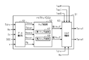
- FIG. 2 is a functional block diagram showing an example of a configuration relating to control of motor torque in a hybrid ECU.
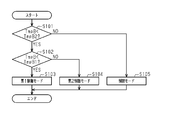
- 9 is a flowchart illustrating an example of a procedure of a control mode selection process.
- the figure which shows an example of a 1st map typically.
- the figure which shows an example of a 2nd map typically.
- FIG. 3A is a functional block diagram illustrating an example of a first map generator
- FIG. 3B is a functional block diagram illustrating an example of a second map generator.
- FIG. The figure which shows an example of a structure of a 1st neural network part typically.
- (A) is a diagram showing an example of a relationship between a required torque pattern and motor power in a first control mode
- (b) is a diagram showing an example of a relationship between a required torque pattern and motor power in a second control mode
- (C) is a diagram showing an example of the relationship between the required torque pattern and the motor power in the restriction mode.
- a vehicle 10 that is a hybrid vehicle includes an engine 11 as a power source and a motor generator (hereinafter, referred to as M / G) 12.
- M / G motor generator
- the rotating shaft 13 of the engine 11 and the rotating shaft 14 of the M / G 12 are connected to each other by a clutch 15 so as to be connectable and disconnectable.
- the rotating shaft 14 of the M / G 12 is connected to driving wheels 18 via a transmission 16 and a driving shaft 17.
- the engine 11 is, for example, a diesel engine having a plurality of cylinders, and generates torque for rotating the rotating shaft 13 by burning fuel in each cylinder.
- the torque generated by the engine 11 is transmitted to the drive wheels 18 via the rotating shaft 14 of the M / G 12, the transmission 16, and the drive shaft 17 when the clutch 15 is in the engaged state.
- the M / G 12 is electrically connected to the battery 20 via the inverter 21.
- the battery 20 is a chargeable / dischargeable secondary battery, and includes a plurality of cells electrically connected to each other.
- the M / G 12 functions as a motor that assists the engine 11 by rotating the rotating shaft 14 by supplying the power stored in the battery 20 via the inverter 21.
- Motor torque Tm generated when M / G 12 functions as a motor is transmitted to drive wheels 18 via transmission 16 and drive shaft 17.
- the M / G 12 functions as a generator that stores the power generated using the rotation of the rotating shaft 14 when the accelerator is off in the battery 20 via the inverter 21, for example.
- the regenerative torque Tr which is a braking torque generated when the M / G 12 functions as a generator, can be controlled in a range equal to or less than a maximum regenerative torque Trmax set for each motor rotation speed Nm.
- the transmission 16 changes the torque of the rotating shaft 14 of the M / G 12 and transmits the changed torque to the driving wheels 18 via the driving shaft 17.
- the transmission 16 is configured so that a plurality of speed ratios Rt can be set.
- the inverter 21 converts a DC voltage from the battery 20 into an AC voltage and supplies power to the M / G 12.
- the inverter 21 converts an AC voltage from the M / G 12 into a DC voltage, supplies the DC voltage to the battery 20, and charges the battery 20.
- the vehicle 10 includes the M / G 12, the inverter 21, and the high-voltage electric circuit 25 having the battery 20, which are high-voltage components.
- a current flowing through the battery 20 when power is supplied from the inverter 21 to the M / G 12 is referred to as a discharge current, and a current flowing through the battery 20 when power is supplied from the inverter 21 to the battery 20 is charged. It is called current.
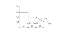
- the range of the battery temperature TmpB which is the temperature of the battery 20, is classified into three regions where the maximum value of the motor torque Tm is different.
- the first region A1 is a region in which the battery temperature TmpB is lower than the switching temperature TmpB1, and in which the first maximum torque Tm1 is defined as the maximum value of the motor torque Tm.
- the second region A2 is a region in which the battery temperature TmpB is equal to or higher than the switching temperature TmpB1 and lower than the limit start temperature TmpB2, and in which the second maximum torque Tm2 smaller than the first maximum torque Tm1 is defined as the maximum value of the motor torque Tm. is there.
- the restriction region A3 is a region where the battery temperature TmpB is equal to or higher than the restriction start temperature TmpB2.
- a temperature equal to or higher than the limit start temperature TmpB2 may be referred to as a limit temperature.
- the restriction region A3 is a region in which a restriction torque Tm3 that is smaller than the second maximum torque Tm2 as the battery temperature TmpB becomes higher than the restriction start temperature TmpB2 is defined.
- the minimum value of the limit torque Tm3 is the minimum limit torque Tm4.
- the engine 11, the clutch 15, the inverter 21, the transmission 16, and the like are controlled by a control device 30 that controls the vehicle 10.
- the control device 30 includes a hybrid ECU 31, an engine ECU 32, an inverter ECU 33, a battery ECU 34, a transmission ECU 35, an information ECU 37, and the like.
- the ECUs 31 to 37 are connected to each other via, for example, a CAN (Control Area Network). .
- the ECUs 31 to 37 are mainly configured by a microcontroller in which a processor, a memory, an input interface, an output interface, and the like are connected to each other via a bus. Each of the ECUs 31 to 37 acquires status information that is information relating to the status of the vehicle 10 via an input interface, and performs various processing based on the acquired status information, a control program and various data stored in a memory. Execute
- the hybrid ECU 31 acquires various state information output from the ECUs 32 to 37 via the input interface. For example, based on a signal from the engine ECU 32, the hybrid ECU 31 acquires the required torque Tdrv, which is the torque required by the driver, and acquires the engine speed Ne, which is the rotation speed of the rotating shaft 13 of the engine 11. That is, the hybrid ECU 31 corresponds to a required torque acquisition unit and a rotation speed acquisition unit.
- the hybrid ECU 31 Based on a signal from the inverter ECU 33, the hybrid ECU 31 calculates a motor rotation speed Nm, which is the rotation speed of the rotating shaft 14 of the M / G 12, a motor temperature TmpM, which is the temperature of the M / G 12, and an inverter temperature, which is the temperature of the inverter 21. Get TmpI. That is, the hybrid ECU 31 corresponds to a temperature acquisition unit. The hybrid ECU 31 acquires the state of charge SOC of the battery 20 in addition to the battery voltage based on the signal from the battery ECU 34 and acquires the battery temperature TmpB, which is the temperature of the battery 20. That is, the hybrid ECU 31 corresponds to a charging rate acquisition unit and a temperature acquisition unit.
- the hybrid ECU 31 acquires the connection / disconnection state of the clutch 15, the gear ratio Rt of the transmission 16, and the like based on a signal from the transmission ECU 35.
- the hybrid ECU 31 acquires the vehicle speed v based on a signal from the information ECU 37. That is, the hybrid ECU 31 corresponds to a vehicle speed acquisition unit.
- the hybrid ECU 31 generates various control signals based on the acquired information, and outputs the generated control signals to the ECUs 32 to 37 via the output interface.
- the hybrid ECU 31 calculates an engine command torque Teref, which is a command torque to the engine 11, and outputs a control signal indicating the calculated engine command torque Teref to the engine ECU 32.
- the hybrid ECU 31 calculates a motor command torque Tmref, which is a command torque for the M / G 12, and outputs a control signal indicating the calculated motor command torque Tmref to the inverter ECU 33.
- the hybrid ECU 31 outputs to the transmission ECU 35 a control signal for instructing connection / disconnection of the clutch 15 and a control signal for instructing the transmission gear ratio Rt in the transmission 16.
- the engine ECU 32 obtains the engine speed Ne and the accelerator operation amount ACC of the accelerator pedal 51, and controls the fuel injection amount and the injection amount so that the torque corresponding to the engine instruction torque Teref input from the hybrid ECU 31 acts on the rotating shaft 13. Control timing, etc.
- the engine ECU 32 calculates the required torque Tdrv based on the accelerator operation amount ACC and the engine speed Ne, and outputs the calculated required torque Tdrv to the hybrid ECU 31.
- the inverter ECU 33 acquires the motor rotation speed Nm, the motor temperature TmpM, and the inverter temperature TmpI, and controls the inverter 21 so that the torque corresponding to the motor instruction torque Tmref input from the hybrid ECU 31 acts on the rotating shaft 14. I do.
- the inverter ECU 33 acquires detection values of a plurality of motor temperature sensors attached to the M / G 12. The highest temperature among the acquired detection values is the motor temperature TmpM.
- the inverter ECU 33 acquires detection values of a plurality of inverter temperature sensors attached to the inverter 21. The highest temperature among the acquired detection values is the inverter temperature TmpI.
- Inverter ECU 33 outputs inverter temperature TmpI to hybrid ECU 31.
- the battery ECU 34 monitors the charge / discharge current of the battery 20 and calculates the state of charge SOC of the battery 20 based on the integrated value of the charge / discharge current.
- the battery ECU 34 acquires the battery voltage and the battery temperature TmpB in addition to the charge / discharge current I of the battery 20.
- the battery ECU 34 acquires detection values of a plurality of battery temperature sensors attached to the battery 20, and outputs the highest temperature among the acquired detection values to the hybrid ECU 31 as the battery temperature TmpB.
- the transmission ECU 35 controls connection and disconnection of the clutch 15 in response to a request for connection and disconnection of the clutch 15 from the hybrid ECU 31. Further, the transmission ECU 35 controls the speed ratio Rt of the transmission 16 based on a control signal indicating the speed ratio Rt from the hybrid ECU 31.
- the information ECU 37 acquires various information based on signals from various sensors which are components of the information acquisition unit 53, and outputs the acquired information to the hybrid ECU 31. For example, the information ECU 37 acquires the vehicle speed v of the vehicle 10 based on a signal from the vehicle speed sensor, and outputs the acquired vehicle speed v to the hybrid ECU 31.
- the hybrid ECU 31 analyzes the state information acquired in the set period T1, and generates a map used for controlling the motor torque Tm in the set period T2 based on the analysis result. Further, the hybrid ECU 31 analyzes the state information acquired in the set period T2, and generates a map used for controlling the motor torque Tm in the set period T3 based on the analyzed result. As described above, when k is an integer equal to or greater than 1, the hybrid ECU 31 generates a map based on the analysis result of the state information acquired in the set period Tk, and uses the generated map to set the map for the set period T (k + 1). The control of the motor torque Tm is performed.
- the setting period Tk can be set according to the use condition of the vehicle and the road environment.
- the set period Tk for a vehicle mainly traveling on a highway such as a large truck used for long-distance transportation may be about several minutes due to a small variation in road environment.
- the set period Tk for a vehicle mainly traveling in an urban area, such as a small truck may be about several tens of seconds due to a large variation in road environment.
- the set period Tk may be a predetermined time or a time that is changed based on an actual traveling state.
- the setting period Tk may be changed so as to be short when the variation in the road environment is large and the change in the accelerator operation amount is large, and to be long when the variation in the road environment is small and the change in the accelerator operation amount is small.
- the hybrid ECU 31 has various functional units that function by executing a program. That is, the hybrid ECU 31 includes a data analysis unit 61, a map update unit 62, and a torque control unit 63.
- the data analysis unit 61 calculates a plurality of feature amounts in the set period Tk based on the state information of the analysis target acquired at a plurality of times in the set period Tk, and outputs analysis result information including the calculated plurality of feature amounts. Output to the map update unit 62.
- the data analysis unit 61 acquires state information to be analyzed, including the required torque Tdrv, the engine speed Ne, the charging current Ic, the state of charge SOC of the battery 20, and the vehicle speed v.
- the data analysis unit 61 calculates the required torque average value Tdave and the required torque variance value Tdvar, which are characteristic amounts, based on the required torque Tdrv, the engine speed Ne, and the vehicle speed v acquired at a plurality of times during the set period Tk. Is calculated.
- the data analysis unit 61 calculates the engine speed average value Neave and the engine speed distribution The value Nevar is calculated.
- the data analysis unit 61 is an amount of power that can be supplied to the battery 20 during the set period T (k + 1) based on the charging current Ic and the state of charge SOC acquired at a plurality of times during the set period Tk. Is calculated.
- the data analysis unit 61 maps the analysis result information including the required torque average value Tdave, the required torque dispersion value Tdvar, the engine speed average value Neave, the engine speed dispersion value Nevar, and the suppliable power amount Pb to the map updating unit 62.
- the map update unit 62 generates a map in which the motor torque Tm is defined according to the required torque Tdrv and the engine speed Ne based on the analysis result information of the data analysis unit 61.
- the map update unit 62 has a first map generation unit 67 that generates a first map M1 (see FIG. 6) that is a map used when the battery temperature TmpB is in the first area A1.
- the map updating unit 62 includes a second map generating unit 69 that generates a second map M2 (see FIG. 7) that is a map used when the battery temperature TmpB is in the second area A2.
- the detailed description of the first map generator 67 and the second map generator 69 will be described later.
- the map updating section 62 outputs the first map M1 generated by the first map generating section 67 and the second map M2 generated by the second map generating section 69 to the torque control section 63.
- the map updating unit 62 updates the first map M1 and the second map M2 by outputting the first map M1 and the second map M2 to the torque control unit 63 for each set period Tk.
- the torque control unit 63 controls the motor torque Tm based on the required torque Tdrv, the battery temperature TmpB, and the first and second maps M1 and M2 generated by the map updating unit 62 for each set period Tk.
- the torque control unit 63 repeatedly executes a mode selection process for selecting a control mode for controlling the motor torque Tm. Then, the torque control unit 63 calculates the motor torque Tm based on the required torque Tdrv, the engine speed Ne, and the control mode selected in the mode selection processing.
- the torque control unit 63 acquires the battery temperature TmpB, and determines whether or not the acquired battery temperature TmpB is lower than the limit start temperature TmpB2 (step S101). . If the battery temperature TmpB is lower than the limit start temperature TmpB2 (step S101: YES), the torque controller 63 determines whether the battery temperature TmpB is lower than the switching temperature TmpB1 (step S102).
- the torque control unit 63 uses the first map M1 to The first control mode in which the torque Tm is controlled is selected (step S103), and a series of processes is temporarily ended.
- the first control mode is a fuel efficiency priority mode in which the motor torque Tm is controlled with the priority on improving the fuel efficiency regardless of the battery temperature TmpB.
- the torque control unit 63 uses the second map M2 to The second control mode in which the torque Tm is controlled is selected (Step S104), and a series of processes is temporarily ended.
- the second control mode is a balance mode in which the motor torque Tm is controlled so as to improve fuel efficiency while suppressing an increase in the battery temperature TmpB.
- the torque control unit 63 uses the map used for controlling the motor torque Tm based on the switching temperature TmpB1 as the first map M1 and the second map. It is configured to switch to the map M2.
- the limit mode is a temperature priority mode in which the motor torque Tm is controlled with the priority given to suppressing a rise in the battery temperature TmpB.
- the first map M1 corresponding to the first control mode includes, for each position corresponding to the required torque Tdrv equal to or less than the maximum required torque TdrvX and the engine speed Ne equal to or less than the maximum engine speed NeX.
- 5 is a map in which a motor torque Tm equal to or less than a first maximum torque Tm1 is defined.
- an area where a motor torque Tm greater than 0 is defined is an assist area.
- 0 is defined as the motor torque Tm in an area other than the assist area (an area where the engine speed Ne is low and high, and an area where the required torque Tdrv is low and high).
- the engine 11 can be assisted with a high motor torque Tm when the engine 11 is in a state of low combustion efficiency, particularly in an acceleration state.
- the engine 11 can be assisted by the M / G 12 to improve fuel efficiency.
- a relatively high motor torque Tm for example, a motor torque larger than the average value of the motor torque Tm in the assist region, is set in an acceleration region in which the engine 11 is in an acceleration state in the assist region of the first map M1.
- Tm is defined.
- the average value of the motor torque Tm is a value obtained by averaging the motor torque Tm greater than 0. That is, the first map M1 is a map in which the assist area is small and the assist frequency by the M / G 12 is low.
- the torque control unit 63 controls the motor torque Tm to a torque selected from the first map M1 according to the required torque Tdrv and the engine speed Ne.
- the second map M2 corresponding to the second control mode includes, for each position corresponding to the required torque Tdrv equal to or less than the maximum required torque TdrvX and the engine speed Ne equal to or less than the maximum engine speed NeX.
- 4 is a map in which a motor torque Tm equal to or less than a second maximum torque Tm2 smaller than the first maximum torque Tm1 is defined.
- the second map M2 is a map in which the assist area is larger than the first map M1 and the frequency of assist by the M / G 12 is higher.
- the average value and the variance value of the motor torque Tm defined in the acceleration region in the second map M2 are smaller than the average value and the variance value of the motor torque Tm defined in the acceleration region of the first map M1, respectively.
- the second map M2 is a map in which the maximum value of the motor torque Tm is smaller and the assist frequency is higher than the first map M1.
- the torque control unit 63 controls the motor torque Tm to a torque selected from the second map M2 according to the required torque Tdrv and the engine speed Ne.
- the torque control unit 63 controls the motor torque Tm such that the maximum value of the motor torque Tm becomes the limit torque Tm3 according to the battery temperature TmpB.
- the limit torque Tm3 becomes smaller than the second maximum torque Tm2 toward the minimum limit torque Tm4 as the battery temperature TmpB increases.
- the torque control unit 63 controls the motor torque Tm to the limit torque Tm3 when the required torque Tdrv is larger than the limit torque Tm3, and when the required torque Tdrv is equal to or less than the limit torque Tm3, the motor torque is reduced to the required torque Tdrv itself. Control Tm.
- the torque control unit 63 sets the motor torque Tm obtained based on the battery temperature TmpB to the motor instruction torque Tmref, and outputs the motor instruction torque Tmref to the inverter ECU 33. Further, the torque control unit 63 sets the torque obtained by subtracting the motor torque Tm from the required torque Tdrv as the engine instruction torque Teref, and outputs the engine instruction torque Teref to the engine ECU 32.
- the first map generation unit 67 and the second map generation unit 69 will be described with reference to FIGS.
- the first map generation unit 67 has various functional units that function by executing a program. That is, the first map generation unit 67 includes the first ANN unit 71 and the first map construction unit 72.
- the second map generating unit 69 has various functional units that function by executing a program. That is, the second map generation unit 69 has a second ANN unit 73 and a second map construction unit 74.
- the first map generation unit 67 and the second map generation unit 69 have the same basic structure except for the conditions when constructing an ANN (Artificial Neural Network). Therefore, the first map generator 67 will be described in detail, and the detailed description of the second map generator 69 will be omitted.
- ANN Artificial Neural Network
- the first ANN unit 71 and the second ANN unit 73 are constructed based on the result of a preliminary simulation performed before the hybrid ECU 31 is mounted.
- the preliminary simulation is performed by inputting into the simulation device 75 several hundred simulation patterns # 111 to # 1ij (i and j are integers of 1 or more) in which various conditions are set in addition to various constraint conditions.
- the constraint condition is a condition regarding the minimum engine torque of the engine 11, the maximum motor torque of the M / G 12, and the like.
- the simulation patterns # 111 to # 1ij are the torque patterns Tdrv # 1 to Tdrv # i of the required torque Tdrv during the set period Tk, the suppliable power amounts Pb # 1 to Pb # j during the set period Tk, and the maximum of the motor power Pm. Consists of a value.
- the simulation device 75 performs a simulation for each of the simulation patterns # 111 to # 1ij by a dynamic programming method for a vehicle type on which the hybrid ECU 31 is mounted. Then, the simulation device 75 obtains an optimization map that minimizes the fuel consumption for each of the simulation patterns # 111 to # 1ij.
- the optimization map is a map in which the motor torque Tm is defined for each position according to the required torque Tdrv and the engine speed Ne.
- the simulation device 75 is configured such that the maximum value of the motor power Pm is the first maximum power Pm1 and the fuel consumption amount is related to the first ANN unit 71 which is the first neural network unit.
- the simulation is performed under the condition of the minimum without considering the battery temperature TmpB.
- the simulation device 75 generates the first optimization maps M # 111 to M # 1ij for each of the simulation patterns # 111 to # 1ij through such a simulation.
- the motor torque Tm defined in the first optimization maps M # 111 to M # 1ij is equal to or less than the first maximum torque Tm1.
- the feature amounts (the required torque average value Tdave and the required torque variance Tdvar) of the simulation patterns # 111 to # 1ij are obtained.
- the engine speed average value Neave, the engine speed dispersion value Nevar, and the suppliable power amount) are set as inputs, and the first optimization maps M # 111 to M # 1ij are set as outputs, and the first ANN unit 71 is set. Let them learn.
- each node constituting the input layer has an activation function in which the feature amount of the set period Tk is a variable.
- Each node constituting the intermediate layer and the output layer includes an activation function in which a plurality of operation values at a plurality of nodes of a previous layer and a plurality of weight values set at a plurality of connection edges are variables.
- the plurality of nodes constituting the output layer correspond to the first optimization maps M # 111 to M # 1ij, respectively.
- the first optimization maps M # 111 to M # 1ij corresponding to the feature amounts in the simulation patterns # 111 to # 1ij are input to the first ANN unit 71 so that the corresponding nodes are output.
- the activation function and the weight of each connection edge are set.
- the first map builder 72 holds the first optimization maps M # 111 to M # 1ij generated by the simulation device 75. Then, based on the plurality of output values of the first ANN unit 71, the first map construction unit 72 generates a plurality of first optimization maps M # 111 to M # 1ij in which the motor power Pm is allowed to reach the first maximum power Pm1. Is interpolated or extrapolated to construct a first map M1.
- the first map M1 is used to drive the M / G 12 with the motor power Pm equal to or less than the first maximum power Pm1, that is, the motor torque Tm equal to or less than the first maximum torque Tm1.
- the simulation device 75 determines that the maximum value of the motor power Pm The simulation of the plurality of simulation patterns # 111 to # 1ij is performed under the condition of the second maximum power Pm2 smaller than the first maximum power Pm1. Then, the simulation device 75 obtains the second optimization maps M # 211 to M # 2ij for each of the simulation patterns # 111 to # 1ij. In this simulation, for example, a condition for a temperature rise value of the battery temperature TmpB may be provided.
- Examples of such conditions include a condition that the temperature rise value is equal to or less than the difference between the switching temperature TmpB1 and the limit start temperature TmpB2, a condition that the temperature rise value is 30 ° C. or less, and the like. By providing such a condition, an excessive increase in the battery temperature TmpB can be suppressed more reliably.
- the activation function of each node and the second optimization map M # 211 to M # 2ij are output when the feature amounts of the simulation patterns # 111 to # 1ij are input to the second ANN unit 73.
- the weight of each connection edge is set.
- the simulation device 75 sets the first optimization map and the second optimization map such that the assist amount (work amount) by the M / G 12 is the same for the simulation pattern in which the torque pattern and the suppliable electric energy are the same. And can be configured.
- the motor torque Tm in the second optimization maps M # 211 to M # 2ij obtained under the second maximum power Pm2 ( ⁇ Pm1) is equal to or less than the second maximum torque Tm2 smaller than the first maximum torque Tm1. .
- the second optimization maps M # 211 to M # 2ij have a minimum fuel consumption under the condition that the maximum value of the motor power Pm is smaller than the first optimization maps M # 111 to M # 1ij. Map. Therefore, the second optimization maps M # 211 to M # 2ij have a lower degree of freedom in the output of the M / G12 than the first optimization maps M # 111 to M # 1ij, and thus the first optimization map M # 111 This is a map in which the assist frequency is higher than that of M # 1ij.
- the second map construction unit 74 holds the second optimization maps M # 211 to M # 2ij generated by the simulation device 75. Then, based on the plurality of output values of the second ANN unit 73, the second map construction unit 74 generates the second optimization maps M # 211 to M # 211 obtained from the simulation in which the motor power Pm is limited to the second maximum power Pm2.
- a second map M2 is constructed by interpolating or extrapolating M # 2ij.
- the second map M2 drives the M / G 12 with a motor power Pm less than the second maximum power Pm2 smaller than the first maximum power Pm1, that is, a motor torque Tm less than the second maximum torque Tm2 smaller than the first maximum torque Tm1. Used to make The second map M2 is a map that drives the M / G 12 more frequently than the first map M1.
- hybrid ECU 31 having the above-described configuration will be described by taking as an example a case where vehicle 10 travels in the first control mode, the second control mode, and the limit mode during a certain set period Tk. explain.
- the amount of assist output by the M / G 12 per unit time is proportional to the amount of power supplied by the battery 20 to the M / G 12 during the unit time, that is, the current value flowing through the battery 20.
- the heat value of the battery 20 is proportional to the square of the value of the current flowing through the battery 20. Therefore, for example, even if the same amount of power is supplied from the battery 20 to the M / G 12 in the set period Tk, the smaller the proportion of the power supply period in the set period Tk, that is, the motor in the set period Tk.
- the larger the variance of the power Pm the greater the amount of heat generated by the M / G 12 during the set period Tk.
- the first control mode is a control mode in which improvement in fuel efficiency is given top priority, and is performed when the battery temperature TmpB belongs to the first area A1, which is a low temperature area (TmpB ⁇ TmpB1). Selected.
- the hybrid ECU 31 controls the motor torque Tm using the first map M1 with a low assist frequency in which the motor power Pm is allowed to reach the first maximum power Pm1. Therefore, the motor power Pm increases intensively during a period in which the condition that the combustion efficiency of the engine 11 is low is satisfied. That is, the first control mode is a control mode in which the heat generated by the battery 20 is large because the current flowing through the battery 20 during the assist is large, but the M / G 12 can assist the engine 11 most efficiently. .
- the second control mode is a control mode in which fuel efficiency is improved while suppressing an increase in the battery temperature TmpB, and the battery temperature TmpB belongs to the second region A2 which is a medium temperature region.
- the hybrid ECU 31 controls the motor torque Tm using the second map M2 with a high assist frequency in which the motor power Pm is limited to the second maximum power Pm2 ( ⁇ Pm1). Therefore, in the second control mode, the engine 11 is continuously assisted with the motor power Pm equal to or less than the second maximum power Pm2 for a longer period than in the first control mode, and the first control mode shown in FIG.
- the engine 11 is assisted by an amount of work substantially equal to.
- the current flowing through the battery 20 at the time of assist is smaller than in the first control mode, so that the increase in the battery temperature TmpB is suppressed.
- This is a control mode similar to the first control mode.
- the limit mode is a control mode in which the engine 11 is assisted with the priority given to suppressing an increase in the battery temperature TmpB.
- the battery temperature TmpB belongs to the limit region A3 which is a high temperature region. (TmpB2 ⁇ TmpB) is selected.
- the limit mode when the required torque Tdrv is equal to or less than the limited torque Tm3 corresponding to the battery temperature TmpB, the motor power Pm at which the motor torque Tm of the M / G 12 becomes the required torque Tdrv is set.
- the limit mode is a control mode in which the motor torque Tm is limited to the limit torque Tm3 to continuously assist the engine 11 and suppress the rise in the battery temperature TmpB more effectively than in the second control mode.
- the hybrid ECU 31 sets the motor torque Tm in the second control mode in which the maximum value of the motor torque Tm is smaller and the assist frequency is higher than in the first control mode.
- the M / G 12 is driven by the first map M1 based on the result of the simulation in which the motor power Pm is allowed to reach the first maximum power Pm1.
- the M / G 12 is driven by the second map M2 based on the result of the simulation in which the motor power Pm is limited to the second maximum power Pm2 ( ⁇ Pm1) or less.
- the hybrid ECU 31 controls the motor torque Tm in the first control mode in which the fuel efficiency is prioritized when the battery temperature TmpB is in the first region A1, and controls the battery temperature TmpB when the battery temperature TmpB is in the second region A2.
- the motor torque Tm is controlled in the second control mode in which the rise is suppressed and the fuel efficiency is balanced.
- the battery temperature TmpB is easily maintained in a state in which the battery temperature TmpB is lower than the limit start temperature TmpB2, that is, a state in which the motor torque Tm can be controlled to a motor torque Tm corresponding to the running state at that time.
- the motor torque Tm can be controlled to a motor torque Tm corresponding to the running state at that time.
- the service life of the battery 20 can be extended by suppressing an excessive increase in the battery temperature TmpB.
- the torque control unit 63 controls the motor torque Tm to the limit torque Tm3.
- the motor torque Tm can be controlled so as to assist the engine 11 while giving priority to a decrease in the battery temperature TmpB. As a result, it is possible to improve fuel efficiency while more reliably suppressing an excessive increase in the battery temperature TmpB.
- the first map generation unit 67 causes the first map construction unit 72 to perform interpolation or extrapolation of the first optimization maps M # 111 to M # 1ij based on the output value of the first ANN unit 71.
- a first map M1 which is an optimization map based on the feature amounts in the set period Tk immediately before the update is constructed.
- the first map generation unit 67 can generate the first map M1 that is the optimum map according to the feature amount in the setting period Tk immediately before the update. That is, the motor torque Tm can be controlled in the next set period using the first map M1 suitable for the running state in the latest set period. Thereby, it is possible to effectively improve the fuel efficiency in a state where the battery temperature TmpB is lower than the switching temperature TmpB1.
- the first map generation unit 67 uses the hundreds of first optimization maps M # 111 to M # 1ij obtained based on the result of the preliminary simulation to optimize maps corresponding to each of the huge feature amount patterns. Can be generated. Therefore, the first map generation unit 67 only needs to hold the hundreds of these first optimization maps M # 111 to M # 1ij, and holds the optimization maps corresponding to each of the huge feature amount patterns. No need. Therefore, the capacity required for the first map generation unit 67 can be suppressed while enabling generation of optimization maps for various patterns. It is to be noted that such an operation and effect is the same for the second map generation unit 69.
- the hybrid ECU 31 is configured to be able to acquire the motor temperature TmpM and the inverter temperature TmpI in addition to the battery temperature TmpB. In such a configuration, the hybrid ECU 31 controls the motor torque Tm based on the second map M2 even when the motor temperature TmpM exceeds the proper motor temperature or when the inverter temperature TmpI exceeds the proper inverter temperature. Is also good.
- a determination is made on the motor temperature TmpM and the inverter temperature TmpI in addition to the battery temperature TmpB.
- the fuel consumption can be improved while suppressing the excessive rise in the temperature of the M / G 12 and the inverter 21.
- the hybrid ECU 31 may be configured to stop the assist of the engine 11 by the M / G 12 when the battery temperature TmpB is equal to or higher than the limit start temperature TmpB2.
- the hybrid ECU 31 may be configured to switch between the first map M1 and the second map M2 based on the switching temperature TmpB1. Therefore, the hybrid ECU 31 may be configured to hold one or more of each of the first map M1 and the second map M2.
Landscapes
- Engineering & Computer Science (AREA)
- Mechanical Engineering (AREA)
- Transportation (AREA)
- Chemical & Material Sciences (AREA)
- Combustion & Propulsion (AREA)
- Automation & Control Theory (AREA)
- Manufacturing & Machinery (AREA)
- Chemical Kinetics & Catalysis (AREA)
- Electrochemistry (AREA)
- General Chemical & Material Sciences (AREA)
- Life Sciences & Earth Sciences (AREA)
- Power Engineering (AREA)
- Physics & Mathematics (AREA)
- Theoretical Computer Science (AREA)
- Sustainable Energy (AREA)
- Sustainable Development (AREA)
- Mathematical Physics (AREA)
- Evolutionary Computation (AREA)
- Artificial Intelligence (AREA)
- Computing Systems (AREA)
- Data Mining & Analysis (AREA)
- Software Systems (AREA)
- General Engineering & Computer Science (AREA)
- Biomedical Technology (AREA)
- Biophysics (AREA)
- Health & Medical Sciences (AREA)
- Computational Linguistics (AREA)
- Molecular Biology (AREA)
- General Health & Medical Sciences (AREA)
- General Physics & Mathematics (AREA)
- Human Computer Interaction (AREA)
- Microelectronics & Electronic Packaging (AREA)
- Electric Propulsion And Braking For Vehicles (AREA)
- Hybrid Electric Vehicles (AREA)
- Secondary Cells (AREA)
Abstract
L'invention concerne un dispositif de commande de moteur qui comprend une partie d'acquisition et une partie de commande de couple. La partie de commande de couple utilise de manière sélective l'une d'une première carte et d'une seconde carte pour commander le couple moteur. La première carte et la seconde carte prescrivent chacune un couple moteur en fonction du couple demandé et de la vitesse du moteur. Lorsqu'une température de batterie est inférieure à une température de commutation qui est inférieure à une température de début de limitation à laquelle le couple moteur est limité, la partie de commande de couple utilise la première carte pour commander le couple moteur. Lorsque la température de batterie est égale ou supérieure à la température de commutation mais inférieure à la température de début de limitation, la partie de commande de couple utilise la seconde carte pour commander le couple moteur. Une région d'assistance de la seconde carte est plus grande qu'une région d'assistance de la première carte, et le couple maximal prescrit dans la région d'assistance de la seconde carte est inférieur au couple maximal prescrit dans la région d'assistance de la première carte.
Priority Applications (3)
| Application Number | Priority Date | Filing Date | Title |
|---|---|---|---|
| EP19834888.0A EP3722167B1 (fr) | 2018-07-13 | 2019-07-10 | Dispositif de commande de moteur |
| CN201980008264.2A CN111683849B (zh) | 2018-07-13 | 2019-07-10 | 电动机控制装置 |
| US16/962,008 US11827209B2 (en) | 2018-07-13 | 2019-07-10 | Motor control device |
Applications Claiming Priority (2)
| Application Number | Priority Date | Filing Date | Title |
|---|---|---|---|
| JP2018133014A JP7122186B2 (ja) | 2018-07-13 | 2018-07-13 | モーター制御装置 |
| JP2018-133014 | 2018-07-13 |
Publications (1)
| Publication Number | Publication Date |
|---|---|
| WO2020013251A1 true WO2020013251A1 (fr) | 2020-01-16 |
Family
ID=69142439
Family Applications (1)
| Application Number | Title | Priority Date | Filing Date |
|---|---|---|---|
| PCT/JP2019/027417 Ceased WO2020013251A1 (fr) | 2018-07-13 | 2019-07-10 | Dispositif de commande de moteur |
Country Status (5)
| Country | Link |
|---|---|
| US (1) | US11827209B2 (fr) |
| EP (1) | EP3722167B1 (fr) |
| JP (1) | JP7122186B2 (fr) |
| CN (1) | CN111683849B (fr) |
| WO (1) | WO2020013251A1 (fr) |
Cited By (1)
| Publication number | Priority date | Publication date | Assignee | Title |
|---|---|---|---|---|
| CN114740381A (zh) * | 2022-02-24 | 2022-07-12 | 北汽福田汽车股份有限公司 | 动力电池及其功率map生成方法、装置及车辆 |
Families Citing this family (3)
| Publication number | Priority date | Publication date | Assignee | Title |
|---|---|---|---|---|
| DE102020208886A1 (de) * | 2020-07-16 | 2022-01-20 | Robert Bosch Gesellschaft mit beschränkter Haftung | Verfahren zum Betreiben eines Fahrzeugs |
| CN112428881B (zh) * | 2020-12-04 | 2022-06-14 | 浙江吉利控股集团有限公司 | 一种用于混合动力车辆的电池加热方法及加热系统 |
| EP4137376A1 (fr) * | 2021-08-20 | 2023-02-22 | Ningbo Geely Automobile Research & Development Co., Ltd. | Procédé d'optimisation adaptative en temps réel d'une répartition de puissance ou de couple dans un véhicule |
Citations (5)
| Publication number | Priority date | Publication date | Assignee | Title |
|---|---|---|---|---|
| JPH09191582A (ja) * | 1996-01-11 | 1997-07-22 | Nissan Motor Co Ltd | 電気自動車制御装置 |
| JP2009090735A (ja) * | 2007-10-04 | 2009-04-30 | Honda Motor Co Ltd | ハイブリッド車両の制御装置 |
| JP2015033154A (ja) | 2013-07-31 | 2015-02-16 | 三菱自動車工業株式会社 | 電池の充放電制御装置 |
| JP2017100473A (ja) * | 2015-11-30 | 2017-06-08 | スズキ株式会社 | ハイブリッド車両のモータアシスト制御装置 |
| WO2017104033A1 (fr) * | 2015-12-16 | 2017-06-22 | ボルボ トラック コーポレーション | Dispositif et procédé permettant de commander un système hybride |
Family Cites Families (18)
| Publication number | Priority date | Publication date | Assignee | Title |
|---|---|---|---|---|
| JP3926518B2 (ja) | 1999-08-27 | 2007-06-06 | 本田技研工業株式会社 | ハイブリッド車両のバッテリ制御装置 |
| JP3904192B2 (ja) * | 2001-11-05 | 2007-04-11 | 本田技研工業株式会社 | 車両駆動装置 |
| JP4538418B2 (ja) * | 2006-02-15 | 2010-09-08 | トヨタ自動車株式会社 | 二次電池の充放電制御装置 |
| DE102007011410A1 (de) * | 2006-03-14 | 2007-11-08 | Mitsubishi Fuso Truck and Bus Corp., Kawasaki | Steuergerät für ein elektrisches Hybridfahrzeug |
| US7797089B2 (en) * | 2006-03-30 | 2010-09-14 | Ford Global Technologies, Llc | System and method for managing a power source in a vehicle |
| JP4379432B2 (ja) * | 2006-05-10 | 2009-12-09 | トヨタ自動車株式会社 | 動力出力装置およびこれを搭載する車両並びに二次電池の設定手法 |
| JP4297948B2 (ja) * | 2007-04-13 | 2009-07-15 | トヨタ自動車株式会社 | ハイブリッド駆動装置およびその制御方法 |
| FR2964612B1 (fr) * | 2010-09-09 | 2014-08-15 | Renault Sa | Procede et dispositif de protection thermique d'un organe electrique de vehicule automobile |
| FR2966991B1 (fr) * | 2010-10-28 | 2018-11-02 | Psa Automobiles Sa. | Procede de limitation du couple maximum que peut delivrer ou recevoir une machine electrique alimentee par une batterie et chaine de traction pour vehicule hybride mettant en oeuvre le procede |
| CN104602939B (zh) * | 2012-09-05 | 2019-03-01 | 丰田自动车株式会社 | 混合动力车辆用驱动装置 |
| JP5772809B2 (ja) * | 2012-12-26 | 2015-09-02 | トヨタ自動車株式会社 | 車両の制御装置 |
| CN105848946B (zh) * | 2013-12-27 | 2017-12-26 | 本田技研工业株式会社 | 车辆以及车辆的控制方法 |
| JP6332172B2 (ja) * | 2015-07-06 | 2018-05-30 | トヨタ自動車株式会社 | ハイブリッド自動車 |
| JP6380304B2 (ja) * | 2015-09-03 | 2018-08-29 | トヨタ自動車株式会社 | ハイブリッド自動車 |
| JP6260595B2 (ja) * | 2015-09-03 | 2018-01-17 | トヨタ自動車株式会社 | ハイブリッド自動車 |
| US10696290B2 (en) * | 2018-02-27 | 2020-06-30 | Ford Global Technologies, Llc | Hybrid vehicle and powertrain |
| KR102726807B1 (ko) * | 2019-12-02 | 2024-11-06 | 현대자동차주식회사 | 하이브리드 차량의 엔진 클러치 결합 제어 방법 |
| US11794588B2 (en) * | 2021-02-04 | 2023-10-24 | Ford Global Technologies, Llc | Feedforward torque limit for electrified powertrain |
-
2018
- 2018-07-13 JP JP2018133014A patent/JP7122186B2/ja active Active
-
2019
- 2019-07-10 EP EP19834888.0A patent/EP3722167B1/fr active Active
- 2019-07-10 US US16/962,008 patent/US11827209B2/en active Active
- 2019-07-10 WO PCT/JP2019/027417 patent/WO2020013251A1/fr not_active Ceased
- 2019-07-10 CN CN201980008264.2A patent/CN111683849B/zh active Active
Patent Citations (5)
| Publication number | Priority date | Publication date | Assignee | Title |
|---|---|---|---|---|
| JPH09191582A (ja) * | 1996-01-11 | 1997-07-22 | Nissan Motor Co Ltd | 電気自動車制御装置 |
| JP2009090735A (ja) * | 2007-10-04 | 2009-04-30 | Honda Motor Co Ltd | ハイブリッド車両の制御装置 |
| JP2015033154A (ja) | 2013-07-31 | 2015-02-16 | 三菱自動車工業株式会社 | 電池の充放電制御装置 |
| JP2017100473A (ja) * | 2015-11-30 | 2017-06-08 | スズキ株式会社 | ハイブリッド車両のモータアシスト制御装置 |
| WO2017104033A1 (fr) * | 2015-12-16 | 2017-06-22 | ボルボ トラック コーポレーション | Dispositif et procédé permettant de commander un système hybride |
Cited By (1)
| Publication number | Priority date | Publication date | Assignee | Title |
|---|---|---|---|---|
| CN114740381A (zh) * | 2022-02-24 | 2022-07-12 | 北汽福田汽车股份有限公司 | 动力电池及其功率map生成方法、装置及车辆 |
Also Published As
| Publication number | Publication date |
|---|---|
| CN111683849B (zh) | 2023-08-15 |
| EP3722167A1 (fr) | 2020-10-14 |
| EP3722167A4 (fr) | 2021-04-28 |
| US11827209B2 (en) | 2023-11-28 |
| JP2020011530A (ja) | 2020-01-23 |
| US20210053554A1 (en) | 2021-02-25 |
| EP3722167B1 (fr) | 2022-10-12 |
| CN111683849A (zh) | 2020-09-18 |
| JP7122186B2 (ja) | 2022-08-19 |
Similar Documents
| Publication | Publication Date | Title |
|---|---|---|
| CN106240569B (zh) | 用于控制多模式动力传动系统的内燃机的运行的方法及设备 | |
| JP4306746B2 (ja) | 車両用電源装置 | |
| WO2020013251A1 (fr) | Dispositif de commande de moteur | |
| CN106627561B (zh) | 对车辆上的储能装置进行再充电的方法和设备 | |
| JP2021020563A (ja) | 車両エネルギ管理システム及び車両エネルギ管理方法 | |
| KR20150068841A (ko) | 배터리의 충방전 제어 방법 및 시스템 | |
| KR102359578B1 (ko) | 하이브리드 차량의 최적 운전점 결정 방법 | |
| WO2023020083A1 (fr) | Procédé d'optimisation adaptative en temps réel d'une répartition de puissance ou de couple dans un véhicule | |
| CN111348030A (zh) | 动力传动系统 | |
| CN109131308A (zh) | 控制混合动力系统的方法和装置 | |
| Hofman et al. | Rule-based energy management strategies for hybrid vehicle drivetrains: A fundamental approach in reducing computation time | |
| JP2013151247A (ja) | ハイブリッド車両の制御装置 | |
| JP5545309B2 (ja) | エネルギ管理システム | |
| CN112572406B (zh) | 控制车辆的方法、装置、存储介质及车辆 | |
| JP2020011531A (ja) | 充放電制御装置 | |
| KR102895287B1 (ko) | 하이브리드 차량의 동력 분배 제어 시스템 및 제어 방법 | |
| JP5089334B2 (ja) | ハイブリッド自動車 | |
| Liu et al. | Real-time control for a parallel hybrid electric vehicle based on Pontryagin's minimum principle | |
| JP2020184857A (ja) | 車両制御装置 | |
| JP6505267B1 (ja) | ハイブリッド車両の制御装置 | |
| JP7234875B2 (ja) | 車両の駆動制御装置 | |
| KR101964234B1 (ko) | 주행거리 확장형 전기 자동차의 발전량 결정방법 | |
| JP2006341708A (ja) | ハイブリッド車の制御装置 | |
| JP6773547B2 (ja) | ハイブリッド自動車の制御装置 | |
| JP7456867B2 (ja) | ハイブリッド車両の制御装置 |
Legal Events
| Date | Code | Title | Description |
|---|---|---|---|
| 121 | Ep: the epo has been informed by wipo that ep was designated in this application |
Ref document number: 19834888 Country of ref document: EP Kind code of ref document: A1 |
|
| ENP | Entry into the national phase |
Ref document number: 2019834888 Country of ref document: EP Effective date: 20200707 |
|
| NENP | Non-entry into the national phase |
Ref country code: DE |