WO2020017059A1 - Terminal d'utilisateur - Google Patents
Terminal d'utilisateur Download PDFInfo
- Publication number
- WO2020017059A1 WO2020017059A1 PCT/JP2018/027404 JP2018027404W WO2020017059A1 WO 2020017059 A1 WO2020017059 A1 WO 2020017059A1 JP 2018027404 W JP2018027404 W JP 2018027404W WO 2020017059 A1 WO2020017059 A1 WO 2020017059A1
- Authority
- WO
- WIPO (PCT)
- Prior art keywords
- pucch
- transmission
- signal
- user terminal
- tpc command
- Prior art date
- Legal status (The legal status is an assumption and is not a legal conclusion. Google has not performed a legal analysis and makes no representation as to the accuracy of the status listed.)
- Ceased
Links
Images




Classifications
-
- H—ELECTRICITY
- H04—ELECTRIC COMMUNICATION TECHNIQUE
- H04W—WIRELESS COMMUNICATION NETWORKS
- H04W52/00—Power management, e.g. Transmission Power Control [TPC] or power classes
- H04W52/04—Transmission power control [TPC]
- H04W52/18—TPC being performed according to specific parameters
- H04W52/22—TPC being performed according to specific parameters taking into account previous information or commands
-
- H—ELECTRICITY
- H04—ELECTRIC COMMUNICATION TECHNIQUE
- H04W—WIRELESS COMMUNICATION NETWORKS
- H04W52/00—Power management, e.g. Transmission Power Control [TPC] or power classes
- H04W52/04—Transmission power control [TPC]
- H04W52/54—Signalisation aspects of the TPC commands, e.g. frame structure
Definitions
- the present invention relates to a user terminal in a next generation mobile communication system.
- LTE Long Term Evolution
- LTE-A LTE Advanced, LTE @ Rel. 10, 11, 12, 13
- LTE @ Rel. 8, 9 LTE @ Rel. 8, 9
- a user terminal transmits an uplink signal (for example, an uplink control channel (for example, PUCCH: Physical Uplink Control Channel),
- an uplink control channel for example, PUCCH: Physical Uplink Control Channel
- the transmission power of at least one of a shared channel for example, PUSCH: Physical Uplink Shared Channel
- a sounding reference signal SRS: Sounding Reference Signal
- TPC transmission power control
- DCI Downlink Control Information
- E-UTRA Evolved Universal Terrestrial Radio Access
- E-UTRAN Evolved Universal Terrestrial Radio Access Network
- an uplink signal for example, an uplink control channel (for example, PUCCH), an uplink shared channel (for example, PUSCH), an uplink reference signal (for example, SRS)
- PUCCH uplink control channel
- PUSCH uplink shared channel
- SRS uplink reference signal
- the TPC command indicated by the TPC command field value in the DCI is not properly accumulated, so that the transmission power of the uplink signal may not be properly controlled.
- the present invention has been made in view of the above, and an object of the present invention is to provide a user terminal capable of appropriately controlling the transmission power of an uplink signal repeatedly transmitted.
- One aspect of the user terminal of the present invention is a transmitting unit that repeatedly transmits an uplink control channel, a receiving unit that receives downlink control information (DCI) including a predetermined field value indicating a transmission power control (TPC) command, And a control unit for controlling accumulation of TPC commands.
- DCI downlink control information
- TPC transmission power control
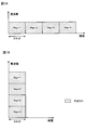
- FIG. 1A and 1B are diagrams showing an example of PUCCH repetition.
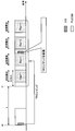
- FIG. 2 is a diagram illustrating an example of transmission power control of the PUCCH repeatedly transmitted according to the first example.
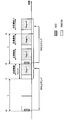
- FIG. 3 is a diagram illustrating an example of transmission power control of the PUCCH repeatedly transmitted according to the second example.
- FIG. 4 is a diagram illustrating another example of transmission power control of the PUCCH repeatedly transmitted according to the second example.
- FIG. 5 is a diagram illustrating another example of transmission power control of the PUCCH repeatedly transmitted according to the third example.
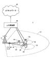
- FIG. 6 is a diagram illustrating an example of a schematic configuration of the wireless communication system according to the present embodiment.
- FIG. 7 is a diagram showing an example of the overall configuration of the radio base station according to the present embodiment.
- FIG. 1A and 1B are diagrams showing an example of PUCCH repetition.
- FIG. 2 is a diagram illustrating an example of transmission power control of the PUCCH repeatedly transmitted according to the first example.
- FIG. 3 is a
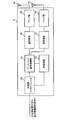
- FIG. 8 is a diagram showing an example of a functional configuration of the radio base station according to the present embodiment.
- FIG. 9 is a diagram showing an example of the overall configuration of the user terminal according to the present embodiment.
- FIG. 10 is a diagram illustrating an example of a functional configuration of the user terminal according to the present embodiment.
- FIG. 11 is a diagram illustrating an example of a hardware configuration of the radio base station and the user terminal according to the present embodiment.
- PUCCH format In NR, a configuration (also referred to as a format, a PUCCH format (PF), etc.) for an uplink control channel (for example, PUCCH) used for transmitting uplink control information (UCI: Uplink Control Information) is being studied.
- PUCCH Physical Uplink Control Channel
- the UCI is acknowledgment information (HARQ-ACK: Hybrid Automatic Repeat Repeat reQuest-ACKnowledge, ACK / NACK: ACKnowledge / Non-ACK) for a downlink shared channel (for example, PDSCH: Physical Downlink Shared Channel), scheduling request (SR : Scheduling Request) and channel state information (CSI: Channel State Information).
- HARQ-ACK Hybrid Automatic Repeat Repeat reQuest-ACKnowledge
- ACK / NACK ACKnowledge / Non-ACK
- CSI Channel State Information
- a PUCCH format (also referred to as PF0, short PUCCH, etc.) used for transmitting 1 or 2 bit UCI (for example, at least one of HARQ-ACK and SR) and transmitted with 1 or 2 symbols;
- a PUCCH format (also referred to as PF1, long PUCCH, etc.) used for transmitting 1 or 2 bit UCI (for example, at least one of HARQ-ACK and SR) and transmitted with 4 symbols or more.
- a PUCCH format (also referred to as PF2, short PUCCH, etc.) used for transmitting UCI larger than 2 bits and transmitted in 1 or 2 symbols;
- a PUCCH format (PF3, also called long PUCCH, etc.) used for transmitting UCI larger than 2 bits and transmitted with 4 symbols or more;
- -A PUCCH format (PF4, also referred to as long PUCCH, etc.) that is used for transmitting UCI larger than 2 bits and is transmitted with 4 symbols or more, and in which a PUCCH resource (PUCCH resource) includes an orthogonal cover code (OCC: Orthogonal Cover Code). ).
- the PUCCH in the PUCCH format described above may be transmitted in a specific cell in a group including one or more cells (also referred to as a cell group (CG: Cell @ Group), a PUCCH group, or the like).
- the specific cell may be, for example, a primary cell (PCCell: Primary @ Cell), a primary secondary cell (PSCell: Primary @ Secondary @ Cell), a secondary cell for PUCCH transmission (SCell: Secondary @ Cell, PUCCH-SCell), or the like.
- the “cell” may be reworded as a serving cell, a component carrier (CC: Component @ Carrier), a carrier, or the like.
- the transmission power of the PUCCH is also referred to as a TPC command (value, increase / decrease value, correction value, etc.) indicated by the value of a predetermined field (also referred to as a TPC command field, a first field, etc.) in DCI. ).
- the transmission power (P PUCCH, b, f, c (P PUCCH, b ) of the transmission opportunity (transmission period or the like) i for the BWPb of the carrier f of the cell c using the index 1 of the power control adjustment state i, q u, q d, l)) may be represented by the following formula (1).
- whether the power control adjustment state has a plurality of states (for example, two states) or a single state may be set according to an upper layer parameter. Further, when a plurality of power control adjustment states are set, one of the plurality of power control adjustment states may be identified by an index l (for example, l ⁇ 0, 1 ⁇ ).
- the power control adjustment state may be called a PUCCH power control adjustment state (PUCCHCpower control adjustment ⁇ state), a first or second state, or the like.
- the transmission opportunity i of the PUCCH is a predetermined period during which the PUCCH is transmitted, and may be composed of, for example, one or more symbols, one or more slots, and the like.
- PCMAX, f, c (i) is, for example, the transmission power (also referred to as the maximum transmission power or the like) of the user terminal set for the carrier f of the cell c at the transmission opportunity i.
- P 0_PUCCH, b, f, c (qu ) is, for example, a parameter (eg, a parameter related to a transmission power offset, a transmission power offset) related to a target reception power set for BWPb of the carrier f of the cell c in the transmission opportunity i. P0 or a target reception power parameter).
- M PUCCH RB, b, g, c (i) is, for example, the number of resource blocks (bandwidth) allocated to PUCCH for transmission opportunity i in uplink BWPb of cell c and carrier f with subcarrier interval ⁇ .
- PL b, g, c (q d ) is, for example, a path loss calculated by the user terminal using the index q d of the reference signal for downlink BWP associated with the uplink BWPb of the carrier f of the cell c.
- ⁇ F_PUCCH (F) is an upper layer parameter given for each PUCCH format.
- ⁇ TF, b, f, c (i) is a transmission power adjustment component (offset) for uplink BWPb of carrier f of cell c.
- g b, f, c (i, l) is a value based on the TPC command of the power control adjustment state index 1 of the uplink BWP of the carrier f of the cell c and the transmission opportunity i (for example, a cumulative value of the TPC command).
- the cumulative value of the TPC command may be represented by Expression (2).
- ⁇ PUCCH, b, f, c (i last , i, K PUCCH , l) is, for example, the carrier f of cell c for transmission opportunity i after the last transmission opportunity i last of PUCCH.
- TPC command indicated by a TPC command field value in a DCI for example, DCI format 1_0 or 1_1 detected in an uplink BWPb of a specific network, or a specific RNTI (Radio Network Temporary Identifier) (for example, TPC-PUCCH- It may be a TPC command indicated by a TPC command field value in a DCI (for example, DCI format 2_2) having a CRC parity bit (CRC scrambled) scrambled in RNTI.
- DCI for example, DCI format 1_0 or 1_1
- RNTI Radio Network Temporary Identifier
- the expressions (1) and (2) are merely examples, and the present invention is not limited thereto.
- the user terminal only needs to control the transmission power of the PUCCH based on at least one parameter exemplified in Expressions (1) and (2), and may include an additional parameter or omit some parameters. May be done. Further, in the above equations (1) and (2), the transmission power of the PUCCH is controlled for each BWP of a certain carrier in a certain cell, but is not limited to this. At least a part of the cell, the carrier, the BWP, and the power control adjustment state may be omitted.
- repetition also referred to as repetition transmission
- DCI Downlink Control Channel
- the configuration by higher layer signaling means from a base station (BS (Base Station), a transmission / reception point (TRP: Transmission / Reception Point), eNB (eNodeB), gNB (NR NodeB), etc.) to a user terminal.
- BS Base Station
- TRP Transmission / Reception Point
- eNB eNodeB
- gNB NR NodeB
- UE User Equipment
- MS Mobile station
- the upper layer signaling may be, for example, at least one of the following: RRC (Radio Resource Control) signaling, MAC (Medium Access Control) signaling (eg, MAC CE (Control Element), MAC PDU (Protocol Data Unit)), Information transmitted by a broadcast channel (for example, PBCH: Physical Broadcast Channel) (for example, a master information block (MIB)); System information (for example, system information block (SIB: System Information Block), minimum system information (RMSI: Remaining Minimum System Information), and other system information (OSI: Other System Information)).
- RRC Radio Resource Control
- MAC Medium Access Control
- MAC CE Control Element
- MAC PDU Protocol Data Unit
- Information transmitted by a broadcast channel for example, PBCH: Physical Broadcast Channel
- MIB master information block
- SIB System Information Block
- SIB System Information Block
- RMSI Remaining Minimum System Information
- OSI Other System Information
- PUCCH repetition may mean that the same PUCCH (UCI) is copied (copied) and transmitted repeatedly.
- duplication of UCI may be to copy at least one of a bit sequence constituting UCI and a bit sequence after encoding. Note that the copied UCI does not necessarily have to be the same bit string as the original UCI.
- PUCCH repetition may be performed in at least one of the frequency domain and the time domain.
- PUCCH may be repeated with a plurality of resources having the same frequency domain and different time domains.
- the PUCCH may be repeated in a plurality of slots in the same cell or in the same partial band (BWP: Bandwidth @ Part) in the same cell.
- BWP Bandwidth @ Part
- PUCCH may be repeated with a plurality of resources having the same time domain and different frequency domains.
- the PUCCH may be repeated in different resource blocks (physical resource blocks (PRB: Physical ⁇ Resource ⁇ Block)) or resource block groups (RBG: Resource ⁇ Block ⁇ Group) in the same slot.
- An RBG may include one or more PRBs.
- FIGS. 1A and 1B show a case where a plurality of resources corresponding to different repetitions are respectively continuous in the time domain or the frequency domain, but they need not be continuous. Further, the plurality of resources may be resources that are different in both the time domain and the frequency domain.
- the PUCCH is assigned to the entire slot, but it is sufficient that at least some symbols in the slot are assigned to the PUCCH.
- the PUCCH repetition may be transmitted from the same TRP, or may be transmitted from a different TRP every predetermined number of repetitions (for example, one repetition).
- TRP may be paraphrased as a network, a radio base station, an antenna device, an antenna panel, a serving cell, a cell, a CC, a carrier, or the like.
- the PUCCH (or a reference signal (for example, a demodulation reference signal (DMRS: Demodulation Reference Signal)) for the PUCCH and a reference signal serving as a reference (
- the reference may have the same spatial relation (spatial relation).
- the spatial relationship may indicate a spatial association between the PUCCH (or the DMRS of the PUCCH) and the reference RS.
- the spatial relationship includes a transmission configuration instruction (TCI: Transmission Configuration Indicator) state (TCI state (TCI-state)), a pseudo collocation (QCL: Quasi-Co-Location), a QCL relationship, and an SRS resource instruction (SRI: Sounding). reference signal Resource Indicator) or the like.
- TCI Transmission Configuration Indicator
- QCL Quasi-Co-Location
- SRI Sounding
- reference signal Resource Indicator or the like.
- the spatial relationship between the PUCCH (or a reference signal (eg, DMRS) related to the PUCCH) and the reference RS may be different between the repetitions. .
- the reference RS is a synchronization signal block (SSB: Synchronization Signal Bock), a channel state information reference signal (CSI-RS: Channel State Information-Reference Signal), a sounding reference signal (SRS: Sounding Reference Signal), and a beam-specific signal. Or a signal configured by expanding, changing, or the like (for example, a signal configured by changing at least one of the density and the period).
- SSB Synchronization Signal Bock
- CSI-RS Channel State Information-Reference Signal
- SRS Sounding Reference Signal
- a beam-specific signal a signal configured by expanding, changing, or the like (for example, a signal configured by changing at least one of the density and the period).
- the TPC command indicated by the value of the TPC command field in the DCI is not appropriately accumulated.
- the transmission power of the repeatedly transmitted PUCCH may not be appropriately controlled.
- a similar problem may occur when PUSCH, SRS, etc. are repeatedly transmitted.
- the present inventors studied a method of appropriately controlling the transmission power of an uplink signal (for example, at least one of PUCCH, PUSCH, and SRS) repeatedly transmitted, and reached the present invention.
- an uplink signal for example, at least one of PUCCH, PUSCH, and SRS
- the TPC command field value in the DCI indicates a transmission power increase / decrease value (dB) as a TPC command.
- the TPC command field values “0”, “1”, “2”, and “3” indicate ⁇ 1, 0, +1 and +3 [dB], respectively. Are not limited to these.
- PUCCH long PUCCHs such as the PUCCH formats 3 and 4 are repeated
- the repeated transmission of the PUCCH may be applied to any PUCCH format.
- PUCCH is repeated in slot units, but is not limited thereto, and may be repeated in one or more symbol units.
- PUCCH repetition will be described.
- PUCCH can be appropriately replaced with PUSCH or SRS when PUSCH or SRS is repeated.
- the user terminal may not expect to receive the DCI including the TPC command field value during the PUCCH repetition. That is, the user terminal does not need to assume that the DCI is received during the repetition of the PUCCH.
- the reflection timing (reflect @ timing) of the TPC command may be a timing after a predetermined period (for example, reception timing of DCI including the TPC command field) and a predetermined period (reflection period) required for reflection of the TPC command.
- the predetermined period may be fixedly set in the specification or may be set by higher layer signaling.
- “timing” may indicate a temporary point, or may indicate a time unit (for example, a slot or a symbol) including the temporary point.
- the base station may control the transmission of the DCI including the TPC command field so that the reflection timing of the TPC command is not in the middle of the repetition of the PUCCH.
- the DCI including the TPC command field is, for example, DCI used for PDSCH scheduling (also referred to as DL assignment, DCI format 1_0 or 1_1 (1_0 / 1_1), etc.) and DCI (TPC used for transmission of TPC command). Command DCI, DCI format 2_2, etc.).
- DCI format 1_0 / 1_1 may include the following fields in addition to the TPC command field: -PUCCH resource identifier (PUCCH resource indicator / indication), ACK / NACK resource identifier (ARI: ACK / NACK Resource Indicator), ACK / NACK resource used for transmitting UCI including HARQ-ACK for PDSCH A field (also referred to as PRI field, ARI field, ARO field, etc.) for offset (also referred to as ARO: ACK / NACK Resource Offset), -It may include a field (feedback timing identification field) for an identifier (PDSCH-to-HARQ_feedback timing indicator) of the feedback timing of the HARQ-ACK. Note that the DL assignment may of course include other fields.
- the reflection period of the TPC command may be determined based on the feedback timing identification field value based on the user terminal.
- the user terminal may determine the PUCCH resource based on the PRI field value (or based on the PRI field value and the index value of the control channel element (CCE: Control @ Channel @ Element) in which the DCI is arranged). Good.
- CCE Control @ Channel @ Element
- the DCI format 2_2 may not include the PRI field, the feedback timing identification field, and the like.
- DCI format 2_2 may include a field for a TPC command.
- DCI format 2_2 may be CRC-scrambled with a specific RNTI (eg, TPC-PUCCH-RNTI).
- FIG. 2 is a diagram showing an example of transmission power control of the PUCCH repeatedly transmitted according to the first example.
- the DCI shown in FIG. 2 may be either DCI format 1_0 / 1_1 or DCI format 2_2.
- the user terminal when the user terminal receives the DCI before the timing t0 before the reflection period k from the start timing t1 of the repeated transmission of the PUCCH, the user terminal accumulates the TPC command indicated by the TPC command field value in the DCI. Based on the value, the transmission power of the PUCCH for four repetitions may be controlled.
- the user terminal indicates the DCI in the accumulated value (for example, g b, f, c (i last , l)) of the latest transmission opportunity i last of the power adjustment state index l.
- the transmission power of the PUCCH of the transmission opportunity i may be controlled based on the cumulative value (for example, g b, f, c (i, l)) obtained by adding the value of the TPC command.
- different transmission opportunities i to i + 3 may be provided for each repetition of the PUCCH.
- the user terminal does not expect to receive the DCI including the TPC command field value after the timing t0 before the reflection period k from the start timing t1 of the repeated transmission of the PUCCH.
- the base station may transmit the DCI including the TPC command field value indicating the TPC command before the timing t0 before the reflection period k from the start timing t1 of the repeated transmission of the PUCCH.
- the base station stops the transmission of the DCI at a timing when the reflection timing is in the middle of the repeated transmission of the PUCCH after the timing t0 before the reflection period k from the start timing t1 of the repeated transmission of the PUCCH.
- the base station controls the transmission timing of the DCI including the TPC command field value indicating the TPC command so that the reflection timing of the TPC command is not in the middle of the repeated transmission of the PUCCH. Therefore, the user terminal can easily control the transmission power of the repeatedly transmitted PUCCH.
- the user terminal controls the transmission power of the PUCCH without being based on the TPC command indicated by the TPC command field value. You may.
- the user terminal may discard (discard) the TPC command indicated by the TPC command field value, or The transmission power of another PUCCH transmitted after the end of the repetition may be controlled based on the accumulated value of the TPC command.
- FIG. 3 is a diagram showing an example of transmission power control of PUCCHs repeatedly transmitted according to the second example.
- the description will focus on the differences from FIG. In FIG. 3, unlike FIG. 2, it may be expected to receive a DCI including a TPC command field after a timing t0 before the reflection period k from the start timing t1 of the repeated transmission of the PUCCH.
- the user terminal performs the operation based on the cumulative value of the TPC command indicated by the TPC command field value in the DCI received before the timing t0 before the reflection period k from the start timing t1 of the repeated transmission of the PUCCH.
- the transmission power of the PUCCH that is repeatedly transmitted may be controlled.
- the user terminal sets the DCI in the accumulated value (for example, g b, f, c (i last , l)) of the latest transmission opportunity i last of the same power adjustment state index l.
- the transmission power of the PUCCH for the transmission opportunity i may be controlled based on a cumulative value (for example, g b, f, c (i, l)) obtained by adding the indicated TPC command values.
- the base station transmits the DCI including the TPC command field value indicating the TPC command even after the timing t0 before the reflection period k from the start timing t1 of the repeated transmission of the PUCCH. May be sent.
- the TPC command field value indicates the value.
- the TPC commands may be discarded without being accumulated.
- FIG. 4 is a diagram showing another example of the transmission power control of the PUCCH repeatedly transmitted according to the second example.
- the description will focus on the differences from FIG. 3.
- the other PUCCH of the PUCCH after the end of the four repetitions may be accumulated for transmission power control (for example, for transmission opportunity i + 1).
- the user terminal indicates the accumulated value (for example, g b, f, c (i)) of the latest transmission opportunity i of the same power adjustment state index l by the DCI.
- the transmission power of the other PUCCH may be controlled based on a cumulative value (for example, g b, f, c (i + 1, l)) obtained by adding the value of the TPC command.
- the base station allows transmission of DCI including the TPC command field value indicating the TPC command. Is done.
- the TPC command indicated by the DCI received during the repetition of the PUCCH is not accumulated for the PUCCH. Therefore, the user terminal can easily control the transmission power of the repeatedly transmitted PUCCH.
- the user terminal controls the transmission power of the subsequent repetition based on the TPC command indicated by the TPC command field value. You may.
- the user terminal determines the reception timing of the DCI based on the accumulated value of the TPC command indicated by the TPC command field value.
- the transmission power of the PUCCH repeated after the reflection period k may be controlled.
- FIG. 5 is a diagram showing another example of the transmission power control of the PUCCH repeatedly transmitted according to the third example.
- a description will be given focusing on differences from FIG. 5
- the reflection period starts from the reception timing t2 of the DCI.
- the TPC command indicated by the TPC command field value may be accumulated for repetitive transmission power control (for example, for transmission opportunity i + 1) after timing t3 after k.
- l for example, g b, f, c
- the transmission power of the repetition may be controlled based on an accumulated value (for example, g b, f, c (i + 1, l)) obtained by adding the value of the TPC command indicated by the DCI to i)).
- the base station allows transmission of DCI including the TPC command field value indicating the TPC command. Is done. Further, the TPC command is accumulated for repetition after the reflection period k from the reception timing of the DCI. For this reason, the user terminal can control the transmission power of the PUCCH repeatedly transmitted more flexibly.
- wireless communication system Wireless communication system
- communication is performed using any of the wireless communication methods according to the above embodiments of the present disclosure or a combination thereof.
- FIG. 6 is a diagram showing an example of a schematic configuration of the wireless communication system according to the present embodiment.
- carrier aggregation (CA) and / or dual connectivity (DC) in which a plurality of basic frequency blocks (component carriers) each having a unit of a system bandwidth (for example, 20 MHz) of an LTE system are applied. can do.
- DC dual connectivity
- the wireless communication system 1 includes LTE (Long Term Evolution), LTE-A (LTE-Advanced), LTE-B (LTE-Beyond), SUPER 3G, IMT-Advanced, 4G (4th generation mobile communication system), and 5G. (5th generation mobile communication system), NR (New Radio), FRA (Future Radio Access), New-RAT (Radio Access Technology), etc., or a system for realizing these.
- LTE Long Term Evolution
- LTE-A LTE-Advanced
- LTE-B LTE-Beyond
- SUPER 3G IMT-Advanced
- 4G 4th generation mobile communication system
- 5G 5th generation mobile communication system
- NR New Radio
- FRA Full Radio Access
- New-RAT Radio Access Technology
- the radio communication system 1 includes a radio base station 11 forming a macro cell C1 having relatively wide coverage, and a radio base station 12 (12a to 12c) arranged in the macro cell C1 and forming a small cell C2 smaller than the macro cell C1. , Is provided. Further, user terminals 20 are arranged in the macro cell C1 and each small cell C2. The arrangement, number, and the like of each cell and the user terminals 20 are not limited to the modes shown in the figure.
- the user terminal 20 can be connected to both the radio base station 11 and the radio base station 12. It is assumed that the user terminal 20 uses the macro cell C1 and the small cell C2 simultaneously using CA or DC. Further, the user terminal 20 may apply CA or DC using a plurality of cells (CC).
- CC a plurality of cells
- Communication between the user terminal 20 and the radio base station 11 can be performed using a carrier having a relatively low frequency band (for example, 2 GHz) and a narrow bandwidth (also referred to as an existing carrier or a legacy carrier).
- a carrier having a relatively high frequency band for example, 3.5 GHz, 5 GHz or the like
- a wide bandwidth may be used between the user terminal 20 and the radio base station 12, The same carrier as that between may be used.
- the configuration of the frequency band used by each wireless base station is not limited to this.
- the user terminal 20 can perform communication using time division duplex (TDD: Time Division Duplex) and / or frequency division duplex (FDD: Frequency Division Duplex) in each cell.
- TDD Time Division Duplex
- FDD Frequency Division Duplex
- a single numerology may be applied, or a plurality of different numerologies may be applied.
- Numerology may be a communication parameter applied to transmission and / or reception of a certain signal and / or channel, for example, subcarrier interval, bandwidth, symbol length, cyclic prefix length, subframe length. , TTI length, number of symbols per TTI, radio frame configuration, specific filtering processing performed by the transceiver in the frequency domain, specific windowing processing performed by the transceiver in the time domain, and the like.
- the numerology may be referred to as different.
- the wireless base station 11 and the wireless base station 12 are connected by wire (for example, an optical fiber compliant with CPRI (Common Public Radio Interface) or an X2 interface) or wirelessly. May be done.
- the wireless base station 11 and each wireless base station 12 are connected to the upper station device 30 and connected to the core network 40 via the upper station device 30.
- the higher station apparatus 30 includes, for example, an access gateway apparatus, a radio network controller (RNC), a mobility management entity (MME), and the like, but is not limited thereto.
- RNC radio network controller
- MME mobility management entity
- each wireless base station 12 may be connected to the upper station device 30 via the wireless base station 11.
- the radio base station 11 is a radio base station having relatively wide coverage, and may be called a macro base station, an aggregation node, an eNB (eNodeB), a transmission / reception point, or the like.
- the radio base station 12 is a radio base station having local coverage, and includes a small base station, a micro base station, a pico base station, a femto base station, a HeNB (Home eNodeB), an RRH (Remote Radio Head), and transmission / reception. It may be called a point or the like.
- the wireless base stations 11 and 12 are not distinguished, they are collectively referred to as a wireless base station 10.
- Each user terminal 20 is a terminal corresponding to various communication systems such as LTE and LTE-A, and may include not only mobile communication terminals (mobile stations) but also fixed communication terminals (fixed stations).
- Orthogonal Frequency Division Multiple Access (OFDMA) is applied to the downlink as a wireless access method, and Single Carrier-Frequency Division Multiple Access (SC-FDMA: Single Carrier) is applied to the uplink. Frequency Division Multiple Access) and / or OFDMA is applied.
- OFDMA Orthogonal Frequency Division Multiple Access
- SC-FDMA Single Carrier-Frequency Division Multiple Access
- OFDMA is a multicarrier transmission scheme in which a frequency band is divided into a plurality of narrow frequency bands (subcarriers), and data is mapped to each subcarrier for communication.
- SC-FDMA divides a system bandwidth into bands each composed of one or a continuous resource block for each terminal, and a single carrier transmission that reduces interference between terminals by using different bands for a plurality of terminals. It is a method.
- the uplink and downlink radio access schemes are not limited to these combinations, and other radio access schemes may be used.
- a downlink shared channel (PDSCH: Physical Downlink Shared Channel), a broadcast channel (PBCH: Physical Broadcast Channel), a downlink L1 / L2 control channel, and the like shared by each user terminal 20 are used. Used.
- the PDSCH transmits user data, upper layer control information, SIB (System @ Information @ Block), and the like. Also, MIB (Master ⁇ Information ⁇ Block) is transmitted by PBCH.
- SIB System @ Information @ Block
- MIB Master ⁇ Information ⁇ Block
- Downlink L1 / L2 control channels include PDCCH (Physical Downlink Control Channel), EPDCCH (Enhanced Physical DownlinkFControl Channel), PCFICH (Physical Control Format Indicator Channel), PHICH (Physical Hybrid-ARQ Indicator Channel) and the like.
- Downlink control information (DCI: Downlink Control Information) including scheduling information of PDSCH and / or PUSCH is transmitted by PDCCH.
- the DCI that schedules DL data reception may be called a DL assignment
- the DCI that schedules UL data transmission may be called an UL grant.
- PCFICH may transmit the number of OFDM symbols used for the PDCCH.
- the PHICH may transmit HARQ (Hybrid Automatic Repeat Repeat reQuest) acknowledgment information (for example, retransmission control information, HARQ-ACK, ACK / NACK, etc.) for the PUSCH.
- HARQ Hybrid Automatic Repeat Repeat reQuest
- the EPDCCH is frequency-division multiplexed with the PDSCH (Downlink Shared Data Channel), and is used for transmission of DCI and the like like the PDCCH.
- an uplink shared channel (PUSCH: Physical Uplink Shared Channel), an uplink control channel (PUCCH: Physical Uplink Control Channel), and a random access channel (PRACH: Physical Random Access Channel) or the like is used.
- PUSCH Physical Uplink Shared Channel
- PUCCH Physical Uplink Control Channel
- PRACH Physical Random Access Channel
- a cell-specific reference signal CRS: Cell-specific Reference Signal
- CSI-RS Channel State Information-Reference Signal
- DMRS Demodulation Reference Signal
- PRS Positioning Reference Signal
- a reference signal for measurement SRS: Sounding Reference Signal
- DMRS reference signal for demodulation
- the DMRS may be called a user terminal specific reference signal (UE-specific Reference Signal). Further, the transmitted reference signal is not limited to these.
- FIG. 7 is a diagram showing an example of the overall configuration of the radio base station according to the present embodiment.
- the wireless base station 10 includes a plurality of transmitting / receiving antennas 101, an amplifier unit 102, a transmitting / receiving unit 103, a baseband signal processing unit 104, a call processing unit 105, and a transmission path interface 106.
- the transmitting / receiving antenna 101, the amplifier unit 102, and the transmitting / receiving unit 103 may be configured to include at least one each.
- the baseband signal processing unit 104 regarding user data, processing of a PDCP (Packet Data Convergence Protocol) layer, division / combination of user data, transmission processing of an RLC layer such as RLC (Radio Link Control) retransmission control, and MAC (Medium Access) Control) Transmission / reception control (for example, HARQ transmission processing), scheduling, transmission format selection, channel coding, inverse fast Fourier transform (IFFT) processing, precoding processing, etc., and transmission / reception processing are performed.
- RLC Radio Link Control
- MAC Medium Access
- Transmission / reception control for example, HARQ transmission processing
- scheduling transmission format selection, channel coding, inverse fast Fourier transform (IFFT) processing, precoding processing, etc.
- IFFT inverse fast Fourier transform
- the transmission / reception section 103 converts the baseband signal pre-coded and output from the baseband signal processing section 104 for each antenna into a radio frequency band, and transmits the radio frequency band.
- the radio frequency signal frequency-converted by the transmitting / receiving section 103 is amplified by the amplifier section 102 and transmitted from the transmitting / receiving antenna 101.
- the transmission / reception unit 103 can be configured by a transmitter / receiver, a transmission / reception circuit, or a transmission / reception device described based on common recognition in the technical field according to the present disclosure. Note that the transmission / reception unit 103 may be configured as an integrated transmission / reception unit, or may be configured from a transmission unit and a reception unit.
- a radio frequency signal received by the transmission / reception antenna 101 is amplified by the amplifier unit 102.
- the transmitting / receiving section 103 receives the upstream signal amplified by the amplifier section 102.
- Transmitting / receiving section 103 frequency-converts the received signal into a baseband signal and outputs the baseband signal to baseband signal processing section 104.
- the baseband signal processing unit 104 performs fast Fourier transform (FFT: Fast Fourier Transform), inverse discrete Fourier transform (IDFT), and error correction on user data included in the input uplink signal. Decoding, reception processing of MAC retransmission control, reception processing of the RLC layer and PDCP layer are performed, and the data is transferred to the upper station apparatus 30 via the transmission path interface 106.
- the call processing unit 105 performs call processing (setting, release, etc.) of a communication channel, state management of the wireless base station 10, management of wireless resources, and the like.
- the transmission path interface 106 transmits and receives signals to and from the higher-level station device 30 via a predetermined interface.
- the transmission path interface 106 transmits and receives signals (backhaul signaling) to and from another wireless base station 10 via an interface between base stations (for example, an optical fiber compliant with CPRI (Common Public Radio Interface), an X2 interface). You may.
- CPRI Common Public Radio Interface
- FIG. 8 is a diagram showing an example of a functional configuration of the radio base station according to the present embodiment. Note that, in this example, functional blocks of characteristic portions in the present embodiment are mainly shown, and it may be assumed that the wireless base station 10 also has other functional blocks necessary for wireless communication.
- the baseband signal processing unit 104 includes at least a control unit (scheduler) 301, a transmission signal generation unit 302, a mapping unit 303, a reception signal processing unit 304, and a measurement unit 305. Note that these configurations need only be included in the radio base station 10, and some or all of the configurations need not be included in the baseband signal processing unit 104.
- the control unit (scheduler) 301 controls the entire wireless base station 10.
- the control unit 301 can be configured from a controller, a control circuit, or a control device described based on common recognition in the technical field according to the present disclosure.
- the control unit 301 controls, for example, signal generation in the transmission signal generation unit 302, signal assignment in the mapping unit 303, and the like. Further, the control unit 301 controls a signal reception process in the reception signal processing unit 304, a signal measurement in the measurement unit 305, and the like.
- the control unit 301 performs scheduling (for example, resource transmission) of system information, a downlink data signal (for example, a signal transmitted on the PDSCH), and a downlink control signal (for example, a signal transmitted on the PDCCH and / or the EPDCCH; acknowledgment information and the like). Quota). Further, control section 301 controls generation of a downlink control signal, a downlink data signal, and the like based on a result of determining whether or not retransmission control is required for an uplink data signal.
- scheduling for example, resource transmission
- a downlink data signal for example, a signal transmitted on the PDSCH
- a downlink control signal for example, a signal transmitted on the PDCCH and / or the EPDCCH; acknowledgment information and the like. Quota
- control section 301 controls generation of a downlink control signal, a downlink data signal, and the like based on a result of determining whether or not retransmission control is required for an uplink data signal.
- the control unit 301 controls scheduling of a synchronization signal (for example, PSS (Primary Synchronization Signal) / SSS (Secondary Synchronization Signal)) and a downlink reference signal (for example, CRS, CSI-RS, and DMRS).
- a synchronization signal for example, PSS (Primary Synchronization Signal) / SSS (Secondary Synchronization Signal)
- a downlink reference signal for example, CRS, CSI-RS, and DMRS.
- the control unit 301 includes an uplink data signal (for example, a signal transmitted on the PUSCH), an uplink control signal (for example, a signal transmitted on the PUCCH and / or PUSCH, acknowledgment information, etc.), a random access preamble (for example, a PRACH). (Transmission signal), scheduling of uplink reference signals and the like.
- an uplink data signal for example, a signal transmitted on the PUSCH
- an uplink control signal for example, a signal transmitted on the PUCCH and / or PUSCH, acknowledgment information, etc.
- a random access preamble for example, a PRACH.
- Transmission signal scheduling of uplink reference signals and the like.
- Transmission signal generation section 302 generates a downlink signal (downlink control signal, downlink data signal, downlink reference signal, etc.) based on an instruction from control section 301, and outputs the generated signal to mapping section 303.
- the transmission signal generation unit 302 can be configured from a signal generator, a signal generation circuit, or a signal generation device described based on common recognition in the technical field according to the present disclosure.
- the transmission signal generation unit 302 generates DCI based on an instruction from the control unit 301, for example.
- the DCI is, for example, at least one of a DL assignment for notifying downlink data allocation information, a UL grant for notifying uplink data allocation information, and a DCI including SFI.
- the downlink data signal is subjected to an encoding process and a modulation process according to an encoding rate, a modulation scheme, and the like determined based on channel state information (CSI: Channel ⁇ State ⁇ Information) from each user terminal 20 or the like.
- the downlink data signal may include information configured by upper layer signaling.
- Mapping section 303 maps the downlink signal generated by transmission signal generation section 302 to a predetermined radio resource based on an instruction from control section 301, and outputs the result to transmission / reception section 103.
- the mapping unit 303 can be configured by a mapper, a mapping circuit, or a mapping device described based on common recognition in the technical field according to the present disclosure.
- the reception signal processing unit 304 performs reception processing (for example, demapping, demodulation, and decoding) on the reception signal input from the transmission / reception unit 103.
- the received signal is, for example, an uplink signal (uplink control signal, uplink data signal, uplink reference signal, etc.) transmitted from the user terminal 20.
- the reception signal processing unit 304 can be configured from a signal processor, a signal processing circuit, or a signal processing device described based on common recognition in the technical field according to the present disclosure.
- the reception signal processing unit 304 outputs the information decoded by the reception processing to the control unit 301. For example, when a PUCCH including HARQ-ACK is received, HARQ-ACK is output to control section 301. Further, the reception signal processing unit 304 outputs the reception signal and / or the signal after the reception processing to the measurement unit 305.
- the measurement unit 305 performs measurement on the received signal.
- the measurement unit 305 can be configured from a measurement device, a measurement circuit, or a measurement device described based on common recognition in the technical field according to the present disclosure.
- the measurement unit 305 may perform RRM (Radio Resource Management) measurement, CSI (Channel State Information) measurement, or the like based on the received signal.
- the measurement unit 305 is configured to receive power (for example, RSRP (Reference Signal Received Power)), reception quality (for example, RSRQ (Reference Signal Received Quality), SINR (Signal to Interference plus Noise Ratio, SNR (Signal to Noise Ratio)).
- Power for example, RSRP (Reference Signal Received Power)
- reception quality for example, RSRQ (Reference Signal Received Quality
- SINR Signal to Interference plus Noise Ratio
- SNR Signal to Noise Ratio
- Signal strength for example, RSSI (Received Signal Strength Indicator)
- channel information for example, CSI
- the measurement result may be output to the control unit 301.
- the transmitting / receiving section 103 may transmit downlink control information (DCI).
- DCI may include at least a predetermined field value (TPC command field value) indicating a TPC command.
- transmitting / receiving section 103 may receive an uplink control channel (PUCCH) that is repeatedly transmitted.
- the transmitting / receiving section 103 may transmit setting information (for example, the number of repetitions, PUCCH resources, and the like) related to the repetitive transmission by higher layer signaling.
- the control unit 301 may control the transmission timing of the DCI including the TPC command field value (first mode).
- the control unit 301 may transmit the DCI before the timing before the reflection period from the start timing of the repeated transmission of the PUCCH.
- the control unit 301 may stop the transmission of the DCI at a timing when the reflection timing is in the middle of the repeated transmission of the PUCCH after the timing before the reflection period from the start timing of the repeated transmission of the PUCCH.
- FIG. 9 is a diagram showing an example of the overall configuration of the user terminal according to the present embodiment.
- the user terminal 20 includes a plurality of transmitting / receiving antennas 201, an amplifier unit 202, a transmitting / receiving unit 203, a baseband signal processing unit 204, and an application unit 205.
- the transmitting / receiving antenna 201, the amplifier unit 202, and the transmitting / receiving unit 203 may be configured to include at least one each.
- the radio frequency signal received by the transmitting / receiving antenna 201 is amplified by the amplifier unit 202.
- the transmission / reception unit 203 receives the downlink signal amplified by the amplifier unit 202.
- the transmitting / receiving section 203 converts the frequency of the received signal into a baseband signal and outputs the baseband signal to the baseband signal processing section 204.
- the transmission / reception unit 203 can be configured from a transmitter / receiver, a transmission / reception circuit, or a transmission / reception device described based on common recognition in the technical field according to the present disclosure. Note that the transmission / reception unit 203 may be configured as an integrated transmission / reception unit, or may be configured from a transmission unit and a reception unit.
- the baseband signal processing unit 204 performs FFT processing, error correction decoding, reception processing for retransmission control, and the like on the input baseband signal.
- the downlink user data is transferred to the application unit 205.
- the application unit 205 performs processing related to layers higher than the physical layer and the MAC layer. Also, of the downlink data, broadcast information may be transferred to the application unit 205.
- uplink user data is input from the application unit 205 to the baseband signal processing unit 204.
- the baseband signal processor 204 performs retransmission control transmission processing (eg, HARQ transmission processing), channel coding, precoding, discrete Fourier transform (DFT) processing, IFFT processing, and the like, and performs transmission / reception processing. Transferred to 203.
- the transmission / reception unit 203 converts the baseband signal output from the baseband signal processing unit 204 into a radio frequency band and transmits the radio frequency band.
- the radio frequency signal frequency-converted by the transmitting / receiving section 203 is amplified by the amplifier section 202 and transmitted from the transmitting / receiving antenna 201.
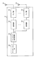
- FIG. 10 is a diagram showing an example of a functional configuration of the user terminal according to the present embodiment. Note that, in this example, functional blocks of characteristic portions in the present embodiment are mainly shown, and it may be assumed that the user terminal 20 also has other functional blocks necessary for wireless communication.
- the baseband signal processing unit 204 of the user terminal 20 includes at least a control unit 401, a transmission signal generation unit 402, a mapping unit 403, a reception signal processing unit 404, and a measurement unit 405. Note that these configurations need only be included in the user terminal 20, and some or all of the configurations need not be included in the baseband signal processing unit 204.
- the control unit 401 controls the entire user terminal 20.
- the control unit 401 can be configured from a controller, a control circuit, or a control device described based on common recognition in the technical field according to the present disclosure.
- the control unit 401 controls, for example, signal generation in the transmission signal generation unit 402, signal assignment in the mapping unit 403, and the like. Further, the control unit 401 controls a signal reception process in the reception signal processing unit 404, a signal measurement in the measurement unit 405, and the like.
- the control unit 401 acquires the downlink control signal and the downlink data signal transmitted from the wireless base station 10 from the reception signal processing unit 404.
- the control unit 401 controls generation of an uplink control signal and / or an uplink data signal based on a result of determining whether or not retransmission control is required for a downlink control signal and / or a downlink data signal.
- control unit 401 When the control unit 401 acquires various information notified from the radio base station 10 from the reception signal processing unit 404, the control unit 401 may update parameters used for control based on the information.
- Transmission signal generation section 402 generates an uplink signal (uplink control signal, uplink data signal, uplink reference signal, etc.) based on an instruction from control section 401 and outputs the generated signal to mapping section 403.
- the transmission signal generation unit 402 can be configured from a signal generator, a signal generation circuit, or a signal generation device described based on common recognition in the technical field according to the present disclosure.
- the transmission signal generation unit 402 generates an uplink control signal related to acknowledgment information, channel state information (CSI), and the like based on an instruction from the control unit 401, for example. Further, transmission signal generating section 402 generates an uplink data signal based on an instruction from control section 401. For example, the transmission signal generation unit 402 is instructed by the control unit 401 to generate an uplink data signal when a downlink control signal notified from the radio base station 10 includes an UL grant.
- CSI channel state information
- Mapping section 403 maps the uplink signal generated by transmission signal generation section 402 to a radio resource based on an instruction from control section 401, and outputs the result to transmission / reception section 203.
- the mapping unit 403 can be configured from a mapper, a mapping circuit, or a mapping device described based on common recognition in the technical field according to the present disclosure.
- the reception signal processing unit 404 performs reception processing (for example, demapping, demodulation, and decoding) on the reception signal input from the transmission / reception unit 203.
- the received signal is, for example, a downlink signal (a downlink control signal, a downlink data signal, a downlink reference signal, etc.) transmitted from the radio base station 10.
- the reception signal processing unit 404 can be configured from a signal processor, a signal processing circuit, or a signal processing device described based on common recognition in the technical field according to the present disclosure.
- the reception signal processing unit 404 can configure a reception unit according to the present disclosure.
- the reception signal processing unit 404 outputs the information decoded by the reception processing to the control unit 401.
- the reception signal processing unit 404 outputs, for example, broadcast information, system information, RRC signaling, DCI, and the like to the control unit 401. Further, the reception signal processing unit 404 outputs the reception signal and / or the signal after the reception processing to the measurement unit 405.
- the measuring unit 405 measures the received signal.
- the measurement unit 405 can be configured from a measurement device, a measurement circuit, or a measurement device described based on common recognition in the technical field according to the present disclosure.
- the measurement unit 405 may perform RRM measurement, CSI measurement, and the like based on the received signal.
- the measurement unit 405 may measure reception power (for example, RSRP), reception quality (for example, RSRQ, SINR, SNR), signal strength (for example, RSSI), channel information (for example, CSI), and the like.
- the measurement result may be output to the control unit 401.
- the transmitting / receiving section 203 may receive downlink control information (DCI).
- DCI may include at least a predetermined field value (TPC command field value) indicating a TPC command.
- transmitting / receiving section 203 may repeatedly transmit an uplink control channel (PUCCH).
- the transmitting / receiving section 203 may receive setting information (for example, the number of repetitions, PUCCH resources, and the like) related to the repetitive transmission by higher layer signaling.
- Control section 401 may control repetitive transmission of an uplink control channel. Specifically, control section 401 may control the transmission power of the uplink control channel that is repeatedly transmitted. Further, the control unit 401 may control the accumulation of the TPC command indicated by the predetermined field value in the DCI.
- the control unit 401 controls the transmission power of the uplink control channel based on the accumulated value of the TPC command when the DCI is received before a timing that is a predetermined period before the start timing of the repeated transmission of the uplink control channel. May be. In this case, the control unit 401 may not expect to receive the DCI after the timing before the predetermined period (first mode, FIG. 2).
- the control unit 401 controls the transmission power of the uplink control channel based on the accumulated value of the TPC command when the DCI is received after a timing that is a predetermined period before the start timing of the repeated transmission of the uplink control channel. (Second embodiment).
- control unit 401 may discard the TPC command (FIG. 3).
- control unit 401 may control the transmission power of another uplink control channel transmitted after the repetition of the uplink control channel based on the accumulated value of the TPC command (FIG. 4).
- the control unit 401 When the DCI is received after a timing that is a predetermined period before the start timing of the repetitive transmission of the uplink control channel, the control unit 401 performs, based on the accumulated value of the TPC command, a predetermined period after the DCI reception timing. Repeated transmission power after the timing may be controlled (third mode, FIG. 5).
- each functional block may be implemented using one device that is physically and / or logically coupled, or may directly and / or physically connect two or more devices that are physically and / or logically separated. Alternatively, they may be connected indirectly (for example, using wired and / or wireless) and implemented using these multiple devices.
- the wireless base station, the user terminal, and the like in the present embodiment may function as a computer that performs the processing of the wireless communication method according to the present disclosure.
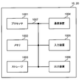
- FIG. 11 is a diagram illustrating an example of a hardware configuration of the radio base station and the user terminal according to the present embodiment.
- the above-described wireless base station 10 and user terminal 20 may be physically configured as a computer device including a processor 1001, a memory 1002, a storage 1003, a communication device 1004, an input device 1005, an output device 1006, a bus 1007, and the like. Good.
- the term “apparatus” can be read as a circuit, a device, a unit, or the like.
- the hardware configuration of the radio base station 10 and the user terminal 20 may be configured to include one or more of the devices illustrated in the drawing, or may be configured to exclude some of the devices.
- processor 1001 may be implemented by one or more chips.
- the functions of the radio base station 10 and the user terminal 20 are performed, for example, by reading predetermined software (program) on hardware such as the processor 1001 and the memory 1002, so that the processor 1001 performs an arithmetic operation and the communication device 1004. It is realized by controlling communication and controlling reading and / or writing of data in the memory 1002 and the storage 1003.
- the processor 1001 controls the entire computer by operating an operating system, for example.
- the processor 1001 may be configured by a central processing unit (CPU: Central Processing Unit) including an interface with a peripheral device, a control device, an arithmetic device, a register, and the like.
- CPU Central Processing Unit
- the above-described baseband signal processing unit 104 (204), call processing unit 105, and the like may be realized by the processor 1001.
- the processor 1001 reads a program (program code), a software module, data, and the like from the storage 1003 and / or the communication device 1004 to the memory 1002, and executes various processes according to these.
- a program program code
- a program that causes a computer to execute at least a part of the operation described in the above embodiment is used.
- the control unit 401 of the user terminal 20 may be implemented by a control program stored in the memory 1002 and operated by the processor 1001, and other functional blocks may be implemented similarly.
- the memory 1002 is a computer-readable recording medium, for example, at least one of ROM (Read Only Memory), EPROM (Erasable Programmable ROM), EEPROM (Electrically EPROM), RAM (Random Access Memory), and other appropriate storage media. It may be constituted by one.
- the memory 1002 may be called a register, a cache, a main memory (main storage device), or the like.
- the memory 1002 can store a program (program code), a software module, and the like that can be executed to implement the wireless communication method according to the present embodiment.
- the storage 1003 is a computer-readable recording medium such as a flexible disk, a floppy (registered trademark) disk, a magneto-optical disk (for example, a compact disk (CD-ROM (Compact Disc) ROM, etc.), a digital versatile disc, At least one of a Blu-ray (registered trademark) disk, a removable disk, a hard disk drive, a smart card, a flash memory device (eg, a card, a stick, a key drive), a magnetic stripe, a database, a server, and other suitable storage media. May be configured.
- the storage 1003 may be called an auxiliary storage device.
- the communication device 1004 is hardware (transmission / reception device) for performing communication between computers via a wired and / or wireless network, and is also referred to as, for example, a network device, a network controller, a network card, a communication module, or the like.
- the communication device 1004 includes a high-frequency switch, a duplexer, a filter, a frequency synthesizer, and the like, for example, in order to realize frequency division duplex (FDD: Frequency Division Duplex) and / or time division duplex (TDD: Time Division Duplex). It may be configured.
- FDD Frequency Division Duplex
- TDD Time Division Duplex
- the transmission / reception antenna 101 (201), the amplifier unit 102 (202), the transmission / reception unit 103 (203), the transmission path interface 106, and the like may be realized by the communication device 1004.
- the input device 1005 is an input device (for example, a keyboard, a mouse, a microphone, a switch, a button, a sensor, and the like) that receives an external input.
- the output device 1006 is an output device that performs output to the outside (for example, a display, a speaker, an LED (Light Emitting Diode) lamp, and the like). Note that the input device 1005 and the output device 1006 may have an integrated configuration (for example, a touch panel).
- the devices such as the processor 1001 and the memory 1002 are connected by a bus 1007 for communicating information.
- the bus 1007 may be configured using a single bus, or may be configured using a different bus for each device.
- the radio base station 10 and the user terminal 20 include a microprocessor, a digital signal processor (DSP), an ASIC (Application Specific Integrated Circuit), an PLD (Programmable Logic Device), an FPGA (Field Programmable Gate Array), and the like. It may be configured to include hardware, and some or all of the functional blocks may be realized using the hardware. For example, the processor 1001 may be implemented using at least one of these pieces of hardware.
- DSP digital signal processor
- ASIC Application Specific Integrated Circuit
- PLD Programmable Logic Device
- FPGA Field Programmable Gate Array
- channels and / or symbols may be signaling.
- the signal may be a message.
- the reference signal may be abbreviated as RS (Reference Signal), and may be referred to as a pilot, a pilot signal, or the like according to an applied standard.
- a component carrier CC may be called a cell, a frequency carrier, a carrier frequency, or the like.
- the radio frame may be configured by one or a plurality of periods (frames) in a time domain.
- the one or more respective periods (frames) forming the radio frame may be referred to as a subframe.
- a subframe may be configured by one or more slots in the time domain.
- the subframe may be a fixed time length (eg, 1 ms) that does not depend on numerology.
- the slot may be configured by one or a plurality of symbols (OFDM (Orthogonal Frequency Division Multiplexing) symbol, SC-FDMA (Single Carrier Frequency Division Multiple Access) symbol, etc.) in the time domain.
- OFDM Orthogonal Frequency Division Multiplexing
- SC-FDMA Single Carrier Frequency Division Multiple Access
- the slot may be a time unit based on numerology.
- the slot may include a plurality of mini slots. Each minislot may be constituted by one or more symbols in the time domain. Also, the mini-slot may be called a sub-slot.
- Radio frames, subframes, slots, minislots, and symbols all represent time units when transmitting signals.
- the radio frame, the subframe, the slot, the minislot, and the symbol may have different names corresponding to each.
- one subframe may be called a transmission time interval (TTI: Transmission @ Time @ Interval)
- TTI Transmission @ Time @ Interval
- a plurality of consecutive subframes may be called a TTI
- one slot or one minislot is called a TTI.
- the subframe and / or TTI may be a subframe (1 ms) in the existing LTE, may be a period shorter than 1 ms (for example, 1 to 13 symbols), or may be a period longer than 1 ms.
- the unit representing the TTI may be called a slot, a minislot, or the like instead of a subframe.
- the TTI refers to, for example, a minimum time unit of scheduling in wireless communication.
- the radio base station performs scheduling to allocate radio resources (frequency bandwidth, transmission power, and the like that can be used in each user terminal) to each user terminal in TTI units.
- radio resources frequency bandwidth, transmission power, and the like that can be used in each user terminal
- TTI is not limited to this.
- the TTI may be a transmission time unit of a channel-encoded data packet (transport block), a code block, and / or a codeword, or may be a processing unit such as scheduling and link adaptation. Note that when a TTI is given, a time interval (for example, the number of symbols) to which a transport block, a code block, and / or a codeword are actually mapped may be shorter than the TTI.
- one slot or one minislot is called a TTI
- one or more TTIs may be the minimum time unit for scheduling. Further, the number of slots (mini-slot number) constituting the minimum time unit of the scheduling may be controlled.
- a TTI having a time length of 1 ms may be called a normal TTI (TTI in LTE@Rel.8-12), a normal TTI, a long TTI, a normal subframe, a normal subframe, a long subframe, or the like.
- a TTI shorter than the normal TTI may be called a shortened TTI, a short TTI, a partial TTI (partial or fractional TTI), a shortened subframe, a short subframe, a minislot, or a subslot.
- a long TTI (for example, a normal TTI, a subframe, etc.) may be read as a TTI having a time length exceeding 1 ms, and a short TTI (for example, a shortened TTI, etc.) may be replaced with a TTI shorter than the long TTI and 1 ms.
- the TTI having the above-described TTI length may be replaced with the TTI.
- a resource block is a resource allocation unit in the time domain and the frequency domain, and may include one or a plurality of continuous subcarriers (subcarriers) in the frequency domain. Further, the RB may include one or a plurality of symbols in a time domain, and may have a length of one slot, one minislot, one subframe, or one TTI. One TTI and one subframe may each be configured by one or a plurality of resource blocks.
- one or more RBs include a physical resource block (PRB: Physical @ RB), a subcarrier group (SCG: Sub-Carrier @ Group), a resource element group (REG: Resource @ Element @ Group), a PRB pair, an RB pair, and the like. May be called.
- a resource block may be composed of one or more resource elements (RE: Resource @ Element).
- RE Resource @ Element
- one RE may be a radio resource area of one subcarrier and one symbol.
- the structures of the above-described radio frame, subframe, slot, minislot, symbol, and the like are merely examples.
- the number of subframes included in a radio frame, the number of slots per subframe or radio frame, the number of minislots included in a slot, the number of symbols and RBs included in a slot or minislot, included in an RB The configuration of the number of subcarriers, the number of symbols in the TTI, the symbol length, the cyclic prefix (CP: Cyclic @ Prefix) length, and the like can be variously changed.
- the information, parameters, and the like described in this specification may be expressed using an absolute value, may be expressed using a relative value from a predetermined value, or may use another corresponding information. May be expressed as For example, a radio resource may be indicated by a predetermined index.
- Names used for parameters and the like in this specification are not restrictive in any way.
- various channels PUCCH (Physical Uplink Control Channel), PDCCH (Physical Downlink Control Channel), etc.
- information elements can be identified by any suitable name, so that various channels assigned to these various channels and information elements can be identified.
- the nomenclature is not a limiting name in any respect.
- information, signals, and the like can be output from an upper layer to a lower layer and / or from a lower layer to an upper layer.
- Information, signals, etc. may be input / output via a plurality of network nodes.
- Information and signals input and output may be stored in a specific place (for example, a memory) or may be managed using a management table. Information and signals that are input and output can be overwritten, updated, or added. The output information, signal, and the like may be deleted. The input information, signal, and the like may be transmitted to another device.
- Notification of information is not limited to the aspects / embodiments described in this specification, and may be performed using other methods.
- the information is notified by physical layer signaling (for example, downlink control information (DCI: Downlink Control Information), uplink control information (UCI: Uplink Control Information)), higher layer signaling (for example, RRC (Radio Resource Control) signaling, It may be implemented by broadcast information (master information block (MIB: Master Information Block), system information block (SIB: System Information Block), etc.), MAC (Medium Access Control) signaling), other signals, or a combination thereof.
- DCI Downlink Control Information
- UCI Uplink Control Information
- RRC Radio Resource Control
- MIB Master Information Block
- SIB System Information Block
- MAC Medium Access Control
- the physical layer signaling may be called L1 / L2 (Layer 1 / Layer 2) control information (L1 / L2 control signal), L1 control information (L1 control signal), or the like.
- the RRC signaling may be referred to as an RRC message, and may be, for example, an RRC connection setup (RRCConnectionSetup) message, an RRC connection reconfiguration (RRCConnectionReconfiguration) message, or the like.
- the MAC signaling may be notified using, for example, a MAC control element (MAC @ CE (Control @ Element)).
- the notification of the predetermined information is not limited to an explicit notification, and is implicit (for example, by not performing the notification of the predetermined information or by another information). May be performed).
- the determination may be made by a value represented by 1 bit (0 or 1), or may be made by a boolean value represented by true or false. , May be performed by comparing numerical values (for example, comparison with a predetermined value).
- software, instructions, information, and the like may be transmitted and received via a transmission medium.
- a transmission medium For example, if the software uses wired technology (coaxial cable, fiber optic cable, twisted pair, digital subscriber line (DSL), etc.) and / or wireless technology (infrared, microwave, etc.), the website, server, etc. , Or when transmitted from another remote source, these wired and / or wireless technologies are included within the definition of the transmission medium.
- system and “network” are used interchangeably.
- base station (BS: Base @ Station)”, “wireless base station”, “eNB”, “gNB”, “cell”, “sector”, “cell group”, “carrier”, and “component”
- carrier may be used interchangeably.
- a base station may also be called a fixed station (fixed @ station), NodeB, eNodeB (eNB), access point (access @ point), transmission point, reception point, femtocell, small cell, and the like.
- a base station can accommodate one or more (eg, three) cells (also called sectors). If the base station accommodates multiple cells, the entire coverage area of the base station can be partitioned into multiple smaller areas, each smaller area being a base station subsystem (eg, a small indoor base station (RRH: Communication services can also be provided by Remote Radio Head)).
- a base station subsystem eg, a small indoor base station (RRH: Communication services can also be provided by Remote Radio Head).
- RRH small indoor base station
- the term “cell” or “sector” refers to part or all of the coverage area of a base station and / or base station subsystem that provides communication services in this coverage.
- MS mobile station
- UE user equipment
- terminal terminal
- a mobile station can be a subscriber station, mobile unit, subscriber unit, wireless unit, remote unit, mobile device, wireless device, wireless communication device, remote device, mobile subscriber station, access terminal, mobile terminal, wireless terminal, by one of ordinary skill in the art. It may also be called a terminal, a remote terminal, a handset, a user agent, a mobile client, a client or some other suitable term.
- the wireless base station in this specification may be replaced with a user terminal.
- each aspect / embodiment of the present disclosure may be applied to a configuration in which communication between a wireless base station and a user terminal is replaced with communication between a plurality of user terminals (D2D: Device-to-Device).
- the configuration may be such that the user terminal 20 has the function of the wireless base station 10 described above.
- words such as “up” and “down” may be read as “side”.
- an uplink channel may be read as a side channel.
- a user terminal in the present specification may be replaced with a wireless base station.
- the configuration may be such that the radio base station 10 has the function of the user terminal 20 described above.
- the operation performed by the base station may be performed by an upper node (upper node) in some cases.
- various operations performed for communication with a terminal include a base station, one or more network nodes other than the base station (eg, Obviously, it can be performed by MME (Mobility Management Entity), S-GW (Serving-Gateway) or the like, but not limited thereto, or a combination thereof.
- MME Mobility Management Entity
- S-GW Serving-Gateway
- Each aspect / embodiment described in this specification may be used alone, may be used in combination, or may be used by switching with execution.
- the processing procedure, sequence, flowchart, and the like of each aspect / embodiment described in this specification may be interchanged as long as there is no inconsistency.
- the methods described herein present elements of various steps in a sample order, and are not limited to the specific order presented.
- LTE Long Term Evolution
- LTE-A Long Term Evolution-Advanced
- LTE-B Long Term Evolution-Beyond
- SUPER 3G IMT-Advanced
- 4G 4th generation mobile
- 5G 5th generation mobile communication system
- FRA FlutureATRadioRAccess
- New-RAT Radio Access Technology
- NR New Radio
- NX New radio access
- FX Fluture generation radio access
- GSM registered trademark
- CDMA2000 Ultra Mobile Broadband
- UMB Ultra Mobile Broadband
- IEEE 802.11 Wi-Fi (registered trademark)
- IEEE 802.16 WiMAX (registered trademark)
- IEEE 802 .20 UWB (Ultra-WideBand), Bluetooth (registered trademark)
- UWB Ultra-WideBand
- Bluetooth registered trademark
- any reference to elements using designations such as "first,” “second,” etc., as used herein, does not generally limit the quantity or order of those elements. These designations may be used herein as a convenient way to distinguish between two or more elements. Thus, reference to a first and second element does not mean that only two elements can be employed or that the first element must precede the second element in any way.
- determining may encompass a wide variety of actions. For example, “determining” means calculating, computing, processing, deriving, investigating, looking up (eg, a table, database, or other data). It may be regarded as “determining” such as searching in a structure), ascertaining, and the like. Also, “determining” includes receiving (eg, receiving information), transmitting (eg, transmitting information), input (input), output (output), and access ( accessing) (e.g., accessing data in a memory) or the like. Also, “judgment (decision)” is regarded as “judgment (decision)” of resolving, selecting, selecting, establishing, comparing, etc. Is also good. That is, “judgment (decision)” may be regarded as “judgment (decision)” of any operation.
- connection refers to any direct or indirect connection or indirect connection between two or more elements. Coupling is meant and may include the presence of one or more intermediate elements between two elements “connected” or “coupled” to each other.
- the coupling or connection between the elements may be physical, logical, or a combination thereof. For example, “connection” may be read as “access”.
- the radio frequency domain can be considered “connected” or “coupled” to each other, such as by using electromagnetic energy having wavelengths in the microwave and / or light (both visible and invisible) regions.
Landscapes
- Engineering & Computer Science (AREA)
- Computer Networks & Wireless Communication (AREA)
- Signal Processing (AREA)
- Mobile Radio Communication Systems (AREA)
Abstract
La présente invention concerne un terminal d'utilisateur comprenant une unité d'émission qui émet de manière répétée un canal de commande de liaison montante, une unité de réception qui reçoit des informations de commande de liaison descendante (DCI) contenant une valeur de champ prédéterminée indiquant une instruction de commande de puissance d'émission (TPC), et une unité de commande qui commande l'accumulation de l'instruction de TPC. La présente invention peut ainsi commander de manière appropriée la puissance d'émission du canal de commande de liaison montante qui est émis de manière répétée.
Priority Applications (2)
| Application Number | Priority Date | Filing Date | Title |
|---|---|---|---|
| PCT/JP2018/027404 WO2020017059A1 (fr) | 2018-07-20 | 2018-07-20 | Terminal d'utilisateur |
| CN201880095767.3A CN112438062B (zh) | 2018-07-20 | 2018-07-20 | 用户终端 |
Applications Claiming Priority (1)
| Application Number | Priority Date | Filing Date | Title |
|---|---|---|---|
| PCT/JP2018/027404 WO2020017059A1 (fr) | 2018-07-20 | 2018-07-20 | Terminal d'utilisateur |
Publications (1)
| Publication Number | Publication Date |
|---|---|
| WO2020017059A1 true WO2020017059A1 (fr) | 2020-01-23 |
Family
ID=69163654
Family Applications (1)
| Application Number | Title | Priority Date | Filing Date |
|---|---|---|---|
| PCT/JP2018/027404 Ceased WO2020017059A1 (fr) | 2018-07-20 | 2018-07-20 | Terminal d'utilisateur |
Country Status (2)
| Country | Link |
|---|---|
| CN (1) | CN112438062B (fr) |
| WO (1) | WO2020017059A1 (fr) |
Cited By (5)
| Publication number | Priority date | Publication date | Assignee | Title |
|---|---|---|---|---|
| JPWO2022030003A1 (fr) * | 2020-08-07 | 2022-02-10 | ||
| EP4093121A4 (fr) * | 2020-02-05 | 2023-06-28 | Vivo Mobile Communication Co., Ltd. | Procédé, appareil, et dispositif de transmission de canal physique de commande de liaison montante, et support |
| JP2023534725A (ja) * | 2020-08-07 | 2023-08-10 | 鴻穎創新有限公司 | Ul送信機会への空間関係の適用 |
| JP2023536955A (ja) * | 2020-08-07 | 2023-08-30 | エルジー エレクトロニクス インコーポレイティド | 無線通信システムにおいて上りリンク送受信方法及び装置 |
| JP2023536922A (ja) * | 2020-08-06 | 2023-08-30 | アップル インコーポレイテッド | マルチtrpを用いたpucch動作のための技術 |
Citations (2)
| Publication number | Priority date | Publication date | Assignee | Title |
|---|---|---|---|---|
| JP2016508302A (ja) * | 2012-11-29 | 2016-03-17 | エルジー エレクトロニクス インコーポレイティド | 無線通信システムにおいて受信確認応答送信方法及び装置 |
| JP2018515987A (ja) * | 2015-05-10 | 2018-06-14 | エルジー エレクトロニクス インコーポレイティド | 無線通信システムにおけるアップリンク送信のための繰り返しレベルを適応させる方法及び装置 |
Family Cites Families (7)
| Publication number | Priority date | Publication date | Assignee | Title |
|---|---|---|---|---|
| US8830883B2 (en) * | 2010-11-16 | 2014-09-09 | Qualcomm Incorporated | Method and apparatus for improving acknowledgement/negative acknowledgement feedback |
| JP6073073B2 (ja) * | 2012-05-10 | 2017-02-01 | シャープ株式会社 | 端末装置、基地局装置および通信方法 |
| WO2014024724A1 (fr) * | 2012-08-10 | 2014-02-13 | シャープ株式会社 | Appareil de station mobile, appareil de station de base, procédé de communication radio et circuit intégré |
| JP5980241B2 (ja) * | 2014-01-14 | 2016-08-31 | 株式会社Nttドコモ | ユーザ端末、無線基地局及び無線通信方法 |
| EP3675566B1 (fr) * | 2014-01-29 | 2022-07-06 | InterDigital Patent Holdings, Inc. | Procédé et appareil d'accès et d'adaptation de liaisons pour transmissions sans fil à couverture améliorée |
| WO2016182392A1 (fr) * | 2015-05-13 | 2016-11-17 | 엘지전자 주식회사 | Procédé et appareil pour commander la puissance d'émission en liaison montante dans un système de communication sans fil qui accepte une communication de type machine |
| WO2018043560A1 (fr) * | 2016-08-31 | 2018-03-08 | 株式会社Nttドコモ | Terminal d'utilisateur, et procédé de communication sans fil |
-
2018
- 2018-07-20 WO PCT/JP2018/027404 patent/WO2020017059A1/fr not_active Ceased
- 2018-07-20 CN CN201880095767.3A patent/CN112438062B/zh active Active
Patent Citations (2)
| Publication number | Priority date | Publication date | Assignee | Title |
|---|---|---|---|---|
| JP2016508302A (ja) * | 2012-11-29 | 2016-03-17 | エルジー エレクトロニクス インコーポレイティド | 無線通信システムにおいて受信確認応答送信方法及び装置 |
| JP2018515987A (ja) * | 2015-05-10 | 2018-06-14 | エルジー エレクトロニクス インコーポレイティド | 無線通信システムにおけるアップリンク送信のための繰り返しレベルを適応させる方法及び装置 |
Cited By (12)
| Publication number | Priority date | Publication date | Assignee | Title |
|---|---|---|---|---|
| EP4093121A4 (fr) * | 2020-02-05 | 2023-06-28 | Vivo Mobile Communication Co., Ltd. | Procédé, appareil, et dispositif de transmission de canal physique de commande de liaison montante, et support |
| US12425133B2 (en) | 2020-02-05 | 2025-09-23 | Vivo Mobile Communication Co., Ltd. | Physical uplink control channel transmission method and apparatus, device and medium |
| JP2023536922A (ja) * | 2020-08-06 | 2023-08-30 | アップル インコーポレイテッド | マルチtrpを用いたpucch動作のための技術 |
| JP7590546B2 (ja) | 2020-08-06 | 2024-11-26 | アップル インコーポレイテッド | マルチtrpを用いたpucch動作のための技術 |
| US12160315B2 (en) | 2020-08-06 | 2024-12-03 | Apple Inc. | Techniques for PUCCH operation with multi-TRP |
| JPWO2022030003A1 (fr) * | 2020-08-07 | 2022-02-10 | ||
| WO2022030003A1 (fr) * | 2020-08-07 | 2022-02-10 | 株式会社Nttドコモ | Terminal, procédé de communication sans fil et station de base |
| JP2023534725A (ja) * | 2020-08-07 | 2023-08-10 | 鴻穎創新有限公司 | Ul送信機会への空間関係の適用 |
| JP2023536955A (ja) * | 2020-08-07 | 2023-08-30 | エルジー エレクトロニクス インコーポレイティド | 無線通信システムにおいて上りリンク送受信方法及び装置 |
| JP7503200B2 (ja) | 2020-08-07 | 2024-06-19 | 鴻穎創新有限公司 | Ul送信機会への空間関係の適用 |
| JP7535653B2 (ja) | 2020-08-07 | 2024-08-16 | エルジー エレクトロニクス インコーポレイティド | 無線通信システムにおいて上りリンク送受信方法及び装置 |
| JP7622069B2 (ja) | 2020-08-07 | 2025-01-27 | 株式会社Nttドコモ | 端末、無線通信方法、基地局及びシステム |
Also Published As
| Publication number | Publication date |
|---|---|
| CN112438062B (zh) | 2024-03-12 |
| CN112438062A (zh) | 2021-03-02 |
Similar Documents
| Publication | Publication Date | Title |
|---|---|---|
| CN112514476B (zh) | 终端、无线通信方法、基站以及系统 | |
| WO2019097646A1 (fr) | Terminal utilisateur et procédé de communication sans fil | |
| WO2020053942A1 (fr) | Terminal utilisateur, et procédé de communication sans fil | |
| WO2019087340A1 (fr) | Équipement d'utilisateur, et procédé de communication sans fil | |
| JPWO2018158923A1 (ja) | ユーザ端末及び無線通信方法 | |
| WO2020021720A1 (fr) | Terminal utilisateur | |
| WO2019069464A1 (fr) | Terminal d'utilisateur et procédé de communication sans fil | |
| WO2019107239A1 (fr) | Terminal d'utilisateur et procédé de communication sans fil | |
| WO2019159292A1 (fr) | Terminal utilisateur et procédé de communication sans fil | |
| WO2019064569A1 (fr) | Terminal utilisateur et procédé de communication radio | |
| WO2019138555A1 (fr) | Terminal d'utilisateur et procédé de communication sans fil | |
| WO2020039483A1 (fr) | Terminal utilisateur | |
| WO2019198136A1 (fr) | Terminal utilisateur et station de base sans fil | |
| CN112438062B (zh) | 用户终端 | |
| JP7299215B2 (ja) | 端末、無線通信方法、基地局及びシステム | |
| WO2019021473A1 (fr) | Dispositif de transmission, dispositif de réception et procédé de communication sans fil | |
| CN111670593B (zh) | 用户终端以及无线通信方法 | |
| WO2019012635A1 (fr) | Terminal utilisateur et procédé de communication sans fil | |
| JP7046926B2 (ja) | 端末、無線通信方法、基地局及びシステム | |
| JP7168667B2 (ja) | 端末、無線通信方法、基地局及びシステム | |
| WO2018207371A1 (fr) | Terminal utilisateur et procédé de communication sans fil | |
| JPWO2019167939A1 (ja) | ユーザ端末及び無線通信方法 | |
| JP6990698B2 (ja) | 端末、無線通信方法、基地局及びシステム | |
| WO2020026425A1 (fr) | Équipement utilisateur et procédé de communication sans fil | |
| WO2019215898A1 (fr) | Terminal utilisateur, et procédé de communication sans fil |
Legal Events
| Date | Code | Title | Description |
|---|---|---|---|
| 121 | Ep: the epo has been informed by wipo that ep was designated in this application |
Ref document number: 18927191 Country of ref document: EP Kind code of ref document: A1 |
|
| NENP | Non-entry into the national phase |
Ref country code: DE |
|
| 122 | Ep: pct application non-entry in european phase |
Ref document number: 18927191 Country of ref document: EP Kind code of ref document: A1 |
|
| NENP | Non-entry into the national phase |
Ref country code: JP |