WO2020021661A1 - Système de climatisation - Google Patents
Système de climatisation Download PDFInfo
- Publication number
- WO2020021661A1 WO2020021661A1 PCT/JP2018/027948 JP2018027948W WO2020021661A1 WO 2020021661 A1 WO2020021661 A1 WO 2020021661A1 JP 2018027948 W JP2018027948 W JP 2018027948W WO 2020021661 A1 WO2020021661 A1 WO 2020021661A1
- Authority
- WO
- WIPO (PCT)
- Prior art keywords
- terminal
- refrigerant
- indoor
- relay
- thermostat
- Prior art date
- Legal status (The legal status is an assumption and is not a legal conclusion. Google has not performed a legal analysis and makes no representation as to the accuracy of the status listed.)
- Ceased
Links
Images




Classifications
-
- F—MECHANICAL ENGINEERING; LIGHTING; HEATING; WEAPONS; BLASTING
- F25—REFRIGERATION OR COOLING; COMBINED HEATING AND REFRIGERATION SYSTEMS; HEAT PUMP SYSTEMS; MANUFACTURE OR STORAGE OF ICE; LIQUEFACTION SOLIDIFICATION OF GASES
- F25B—REFRIGERATION MACHINES, PLANTS OR SYSTEMS; COMBINED HEATING AND REFRIGERATION SYSTEMS; HEAT PUMP SYSTEMS
- F25B49/00—Arrangement or mounting of control or safety devices
- F25B49/005—Arrangement or mounting of control or safety devices of safety devices
-
- F—MECHANICAL ENGINEERING; LIGHTING; HEATING; WEAPONS; BLASTING
- F24—HEATING; RANGES; VENTILATING
- F24F—AIR-CONDITIONING; AIR-HUMIDIFICATION; VENTILATION; USE OF AIR CURRENTS FOR SCREENING
- F24F11/00—Control or safety arrangements
- F24F11/30—Control or safety arrangements for purposes related to the operation of the system, e.g. for safety or monitoring
- F24F11/32—Responding to malfunctions or emergencies
- F24F11/36—Responding to malfunctions or emergencies to leakage of heat-exchange fluid
-
- F—MECHANICAL ENGINEERING; LIGHTING; HEATING; WEAPONS; BLASTING
- F24—HEATING; RANGES; VENTILATING
- F24F—AIR-CONDITIONING; AIR-HUMIDIFICATION; VENTILATION; USE OF AIR CURRENTS FOR SCREENING
- F24F11/00—Control or safety arrangements
- F24F11/70—Control systems characterised by their outputs; Constructional details thereof
- F24F11/80—Control systems characterised by their outputs; Constructional details thereof for controlling the temperature of the supplied air
- F24F11/86—Control systems characterised by their outputs; Constructional details thereof for controlling the temperature of the supplied air by controlling compressors within refrigeration or heat pump circuits
-
- F—MECHANICAL ENGINEERING; LIGHTING; HEATING; WEAPONS; BLASTING
- F24—HEATING; RANGES; VENTILATING
- F24F—AIR-CONDITIONING; AIR-HUMIDIFICATION; VENTILATION; USE OF AIR CURRENTS FOR SCREENING
- F24F2110/00—Control inputs relating to air properties
- F24F2110/10—Temperature
- F24F2110/12—Temperature of the outside air
-
- F—MECHANICAL ENGINEERING; LIGHTING; HEATING; WEAPONS; BLASTING
- F24—HEATING; RANGES; VENTILATING
- F24F—AIR-CONDITIONING; AIR-HUMIDIFICATION; VENTILATION; USE OF AIR CURRENTS FOR SCREENING
- F24F2140/00—Control inputs relating to system states
-
- F—MECHANICAL ENGINEERING; LIGHTING; HEATING; WEAPONS; BLASTING
- F24—HEATING; RANGES; VENTILATING
- F24F—AIR-CONDITIONING; AIR-HUMIDIFICATION; VENTILATION; USE OF AIR CURRENTS FOR SCREENING
- F24F2221/00—Details or features not otherwise provided for
- F24F2221/54—Heating and cooling, simultaneously or alternatively
-
- F—MECHANICAL ENGINEERING; LIGHTING; HEATING; WEAPONS; BLASTING
- F25—REFRIGERATION OR COOLING; COMBINED HEATING AND REFRIGERATION SYSTEMS; HEAT PUMP SYSTEMS; MANUFACTURE OR STORAGE OF ICE; LIQUEFACTION SOLIDIFICATION OF GASES
- F25B—REFRIGERATION MACHINES, PLANTS OR SYSTEMS; COMBINED HEATING AND REFRIGERATION SYSTEMS; HEAT PUMP SYSTEMS
- F25B13/00—Compression machines, plants or systems, with reversible cycle
-
- F—MECHANICAL ENGINEERING; LIGHTING; HEATING; WEAPONS; BLASTING
- F25—REFRIGERATION OR COOLING; COMBINED HEATING AND REFRIGERATION SYSTEMS; HEAT PUMP SYSTEMS; MANUFACTURE OR STORAGE OF ICE; LIQUEFACTION SOLIDIFICATION OF GASES
- F25B—REFRIGERATION MACHINES, PLANTS OR SYSTEMS; COMBINED HEATING AND REFRIGERATION SYSTEMS; HEAT PUMP SYSTEMS
- F25B2500/00—Problems to be solved
- F25B2500/22—Preventing, detecting or repairing leaks of refrigeration fluids
- F25B2500/222—Detecting refrigerant leaks
-
- F—MECHANICAL ENGINEERING; LIGHTING; HEATING; WEAPONS; BLASTING
- F25—REFRIGERATION OR COOLING; COMBINED HEATING AND REFRIGERATION SYSTEMS; HEAT PUMP SYSTEMS; MANUFACTURE OR STORAGE OF ICE; LIQUEFACTION SOLIDIFICATION OF GASES
- F25B—REFRIGERATION MACHINES, PLANTS OR SYSTEMS; COMBINED HEATING AND REFRIGERATION SYSTEMS; HEAT PUMP SYSTEMS
- F25B2700/00—Sensing or detecting of parameters; Sensors therefor
- F25B2700/21—Temperatures
- F25B2700/2104—Temperatures of an indoor room or compartment
-
- F—MECHANICAL ENGINEERING; LIGHTING; HEATING; WEAPONS; BLASTING
- F25—REFRIGERATION OR COOLING; COMBINED HEATING AND REFRIGERATION SYSTEMS; HEAT PUMP SYSTEMS; MANUFACTURE OR STORAGE OF ICE; LIQUEFACTION SOLIDIFICATION OF GASES
- F25B—REFRIGERATION MACHINES, PLANTS OR SYSTEMS; COMBINED HEATING AND REFRIGERATION SYSTEMS; HEAT PUMP SYSTEMS
- F25B2700/00—Sensing or detecting of parameters; Sensors therefor
- F25B2700/21—Temperatures
- F25B2700/2106—Temperatures of fresh outdoor air
-
- F—MECHANICAL ENGINEERING; LIGHTING; HEATING; WEAPONS; BLASTING
- F25—REFRIGERATION OR COOLING; COMBINED HEATING AND REFRIGERATION SYSTEMS; HEAT PUMP SYSTEMS; MANUFACTURE OR STORAGE OF ICE; LIQUEFACTION SOLIDIFICATION OF GASES
- F25B—REFRIGERATION MACHINES, PLANTS OR SYSTEMS; COMBINED HEATING AND REFRIGERATION SYSTEMS; HEAT PUMP SYSTEMS
- F25B49/00—Arrangement or mounting of control or safety devices
- F25B49/02—Arrangement or mounting of control or safety devices for compression type machines, plants or systems
Definitions
- Air conditioning system that operates the air conditioner with an on or off signal from the thermostat
- the air conditioning system includes a controller that controls the air conditioner, a thermostat, a group of connection lines, a relay, and a leak detection sensor.
- the thermostat measures the temperature of the air-conditioned space, changes the contacts to ON or OFF according to the measurement result, and switches the input / non-input of the control signal to the controller to operate the components of the air conditioner. Let it.
- the connection line group electrically connects the thermostat and the controller.
- the relay conducts or shuts off at least one of a first connection line for operating the compressor of the air conditioner and a second connection line for operating the indoor fan of the air conditioner in the group of connection lines. Switch to one of the states.
- the leak detection sensor detects a leak of the refrigerant from the air conditioner and outputs a signal for operating the relay.
- the first connection line for operating the compressor of the air conditioner and the indoor fan of the air conditioner are operated regardless of the control signal of the thermostat.
- At least one of the second connection lines can be switched to one of a conduction state and a cutoff state.
- the air conditioning system according to the second aspect is the air conditioning system according to the first aspect, wherein the connection line group further includes a third connection line for operating a four-way switching valve of the air conditioner.
- the connection line group further includes a third connection line for operating a four-way switching valve of the air conditioner.
- the air conditioning system according to the third aspect is the air conditioning system according to the first aspect or the second aspect, and further includes a heater provided separately from the air conditioner for heating the space to be air-conditioned.
- the connection line group further includes a fourth connection line for operating the heater.
- An air conditioning system is the air conditioning system according to the first aspect, wherein the connection line group further includes a fifth connection line for transmitting a signal from the controller to the thermostat to notify that an abnormality has occurred.
- the relay switches the fifth connection line to one of a conductive state and a cutoff state.
- the air conditioning system according to a fifth aspect is the air conditioning system according to any one of the first aspect to the fourth aspect, wherein each connection line of the connection line group includes at least one of a communication line and a terminal.
- the air conditioning system according to the sixth aspect is the air conditioning system according to any one of the first aspect to the fifth aspect, and includes a use side unit and a heat source side unit.
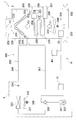
- FIG. 2 is a block diagram showing an electrical connection state of a controller and a thermostat in the air conditioning system according to one embodiment of the present invention.
- 3 is a control flowchart of the air conditioning system.
- 9 is a control flowchart of the air conditioning system after a cooling operation mode is selected.
- 9 is a control flowchart of the air conditioning system after a heating operation mode is selected. It is a control flowchart of the air conditioning system after the heating operation mode is selected, and is a flowchart of control for switching from the heat pump heating operation to another heat source heating operation.
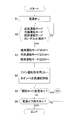
- FIG. 5 is an operation flowchart of a communication line conduction / shutoff relay by a relay controller.
- 9 is an operation flowchart of a communication line conduction / shutoff relay by the relay controller of the first modified example.
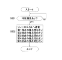
- 9 is an operation flowchart of a communication line conduction / shutoff relay by a relay controller according to a second modified example.
- FIG. 1 is a schematic diagram illustrating an arrangement of an air conditioning system 1 according to an embodiment of the present invention.
- FIG. 2 is a schematic configuration diagram of the air conditioning system 1. 1 and 2, an air conditioning system 1 is a device used for air conditioning of a house or a building.
- the air conditioning system 1 is installed in a house 100 having a two-story structure.
- a house 100 rooms 101 and 102 are provided on the first floor, and rooms 103 and 104 are provided on the second floor.
- the basement 105 is provided in the house 100.
- the air conditioning system 1 is a so-called duct type air conditioning system.
- the air conditioning system 1 includes an indoor unit 2, an outdoor unit 3, refrigerant communication tubes 306 and 307, and a duct 209 for sending air conditioned by the indoor unit 2 to the rooms 101 to 104.
- the duct 209 branches into the rooms 101 to 104 and is connected to the ventilation holes 101a to 104a of the rooms 101 to 104.
- the indoor unit 2, the outdoor unit 3, and the refrigerant communication tubes 306 and 307 are integrally referred to as an air conditioner 10.
- the indoor unit 2, the outdoor unit 3, and the refrigerant communication pipes 306 and 307 constitute a heat pump unit 360 for heating the room by a vapor compression refrigeration cycle.
- the gas furnace unit 205 which is a part of the indoor unit 2, constitutes another heat source unit 270 that heats the room using a heat source different from the heat pump unit 360 (here, heat generated by gas combustion).
- the indoor unit 2 includes the gas furnace unit 205 that forms the separate heat source unit 270 in addition to the unit that forms the heat pump unit 360.
- the indoor unit 2 takes in the air in the rooms 101 to 104 into the housing 230 and supplies the air conditioned by the heat pump unit 360 and another heat source unit 270 (gas furnace unit 205) into the rooms 101 to 104. It also has an indoor fan 240 for performing the operation.
- the indoor unit 2 includes a blow-off air temperature sensor 233 for detecting a blow-off air temperature Trd which is a temperature of air at an air outlet 231 of the housing 230, and an indoor temperature An indoor temperature sensor 234 for detecting Tr is provided.
- the indoor temperature sensor 234 may be provided in the rooms 101 to 104 instead of the indoor unit 2.
- the refrigerant circuit 320 is configured by connecting the indoor unit 2 and the outdoor unit 3 via the refrigerant communication pipes 306 and 307.
- the refrigerant communication pipes 306 and 307 are refrigerant pipes installed locally when the air conditioner 10 is installed.
- the indoor unit 2 is installed in the basement 105 of the house 100.
- the installation place of the indoor unit 2 is not limited to the basement 105, and may be disposed in another indoor.
- the indoor unit 2 includes an indoor heat exchanger 242 as a refrigerant radiator that heats air by radiating the refrigerant in the refrigeration cycle, and an indoor expansion valve 241.
- the indoor expansion valve 241 reduces the pressure of the refrigerant circulating in the refrigerant circuit 320 during the cooling operation and causes the refrigerant to flow to the indoor heat exchanger 242.
- the indoor expansion valve 241 is an electric expansion valve connected to the liquid side of the indoor heat exchanger 242.
- the indoor heat exchanger 242 is arranged at the most leeward side in the ventilation path from the air inlet 232 to the air outlet 231 formed in the housing 230.
- the outdoor unit 3 is installed outside the house 100.
- the outdoor unit 3 includes a compressor 321, an outdoor heat exchanger 323, an outdoor expansion valve 324, and a four-way switching valve 328.
- the compressor 321 is a hermetic compressor in which a compression element (not shown) and a compressor motor 322 that rotationally drives the compression element are accommodated in a casing.
- Power is supplied to the compressor motor 322 via an inverter device (not shown), and the operating capacity can be varied by changing the frequency (that is, the number of revolutions) of the inverter device. ing.
- the outdoor heat exchanger 323 is a heat exchanger that functions as a refrigerant evaporator that evaporates the refrigerant in the refrigeration cycle with outdoor air.
- An outdoor fan 325 for sending outdoor air to the outdoor heat exchanger 323 is provided near the outdoor heat exchanger 323.
- the outdoor fan 325 is rotatably driven by an outdoor fan motor 326.
- the outdoor expansion valve 324 reduces the pressure of the refrigerant circulating in the refrigerant circuit 320 during the heating operation and causes the refrigerant to flow to the outdoor heat exchanger 323.
- the outdoor expansion valve 324 is an electric expansion valve connected to the liquid side of the outdoor heat exchanger 323.
- the outdoor unit 3 is provided with an outdoor temperature sensor 327 for detecting the temperature of outdoor air outside the house 100 in which the outdoor unit 3 is disposed, that is, the outdoor temperature Ta.
- the four-way switching valve 328 is a valve that switches the direction of the flow of the refrigerant.
- the four-way switching valve 328 connects the discharge side of the compressor 321 to the gas side of the outdoor heat exchanger 323 and also connects the suction side of the compressor 321 to the gas refrigerant communication pipe 307 (cooling operation state). : See the solid line of the four-way switching valve 328 in FIG. 2).
- the outdoor heat exchanger 323 functions as a refrigerant condenser
- the indoor heat exchanger 242 functions as a refrigerant evaporator.
- the four-way switching valve 328 connects the discharge side of the compressor 321 and the gas refrigerant communication pipe 307 and also connects the suction side of the compressor 321 and the gas side of the outdoor heat exchanger 323 (heating operation). State: See broken line of four-way switching valve 328 in FIG. 2).
- the indoor heat exchanger 242 functions as a refrigerant condenser
- the outdoor heat exchanger 323 functions as a refrigerant evaporator.
- the separate heat source unit 270 is configured by the gas furnace unit 205 that is a part of the indoor unit 2 of the air conditioner 10.
- the gas furnace unit 205 is provided in a housing 230 installed in the basement 105 of the house 100.
- the gas furnace unit 205 is a gas-fired heating device, and includes a fuel gas valve 251, a furnace fan 252, a combustion unit 254, a furnace heat exchanger 255, an air supply pipe 256, and an exhaust pipe 257. I have.
- the fuel gas valve 251 is composed of an electromagnetic valve or the like that can be controlled to open and close, and is provided on a fuel gas supply pipe 258 extending from outside the housing 230 to the combustion section 254.
- As the fuel gas natural gas, oil gas, or the like is used.
- the furnace fan 252 is a fan that takes in air into the combustion unit 254 through the air supply pipe 256, sends air to the furnace heat exchanger 255, and then discharges the air from the exhaust pipe 257 to generate an air flow.
- the furnace fan 252 is rotatably driven by a furnace fan motor 253.
- the combustion unit 254 is a device that burns a mixed gas of fuel gas and air by a gas burner or the like (not shown) to obtain a high-temperature combustion gas.
- the furnace heat exchanger 255 is a heat exchanger that heats the air by radiating the combustion gas obtained in the combustion unit 254, and the air is radiated by a heat source different from the heat pump unit 360 (here, heat generated by gas combustion). It functions as a separate heat source radiator for heating the heat source.
- the furnace heat exchanger 255 is disposed on the windward side of the indoor heat exchanger 242 as a refrigerant radiator in a ventilation path from the air inlet 232 to the air outlet 231 formed in the housing 230.
- the indoor fan 240 transfers the air heated by the indoor heat exchanger 242 as a refrigerant radiator constituting the heat pump section 360 and the furnace heat exchanger 255 as a separate heat source radiator constituting the separate heat source section 270 to the rooms 101 to 104. It is a blower for supplying inside.
- the indoor fan 240 is disposed on the windward side of both the indoor heat exchanger 242 and the furnace heat exchanger 255 in the ventilation path from the air inlet 232 to the air outlet 231 formed in the housing 230.
- the indoor fan 240 has a blade 243 and a fan motor 244 that drives the blade 243 to rotate.
- the indoor unit 2 is equipped with an indoor control board 21 that controls the operation of each unit of the indoor unit 2.
- the outdoor unit 3 includes an outdoor control board 31 that controls the operation of each unit of the outdoor unit 3.
- the indoor-side control board 21 and the outdoor-side control board 31 have a microcomputer or the like, and exchange control signals with the thermostat 40. Further, control signals are not exchanged between the indoor control board 21 and the outdoor control board 31.
- a control device including the indoor control board 21 and the outdoor control board 31 is referred to as a controller 30.
- FIG. 3 is a block diagram showing an electrical connection state between the controller 30 and the thermostat 40 in the air conditioning system 1 according to the first embodiment of the present invention.
- the thermostat 40 is attached to the indoor space in the same manner as the indoor unit 2.
- the place where the thermostat 40 and the indoor unit 2 are attached may be different places in the indoor space.
- the thermostat 40 is connected to a control system of each of the indoor unit 2 and the outdoor unit 3 by a communication line.
- the transformer 20 transforms the voltage of the commercial power supply 90 to a usable low voltage, and supplies the voltage to the indoor unit 2, the outdoor unit 3, and the thermostat 40 via the power supply lines 801 and 802.
- the terminal block 210 includes a first terminal, a second terminal, a terminal R, a terminal C, a terminal G, a terminal W1, a terminal W2, a terminal Y1, a terminal Y2, a terminal O, and a terminal L in order from the top in FIG. It is arranged in.
- terminal 1 is the terminal of the terminal block 210 of the indoor control board 21
- terminal 2 is the terminal of the terminal block 210 of the indoor control board 21
- terminal R is the terminal of the terminal block 210 of the indoor control board 21
- terminal C is the terminal of the terminal block 210 of the indoor control board 21
- terminal W1 is the terminal of the terminal block 210 of the indoor control board 21
- terminal R is the terminal of the terminal block 210 of the indoor control board 21
- terminal Ri is referred to as “terminal Ri”, “terminal Ci”, “terminal Gi”, “terminal W1i”, “terminal W2i”, “terminal Y1i”, “terminal Y2i”, “terminal Oi”, and “terminal Li”.
- the terminal Ri and the power supply line 801 are connected. Further, the terminal Ci and the power supply line 802 are connected. Further, the terminal Gi, the terminal W1i, the terminal W2i, the terminal Y1i, the terminal Y2i, the terminal Oi, and the terminal Li are connected to the indoor microcomputer 32.
- the indoor microcomputer 32 is connected to the thermostat 40 by at least the power supply line SGR, the common line SGC, the fan operation command communication line SG1, and the first compressor operation command communication line SG4.
- a converter (not shown) is connected between each input port of the indoor microcomputer 32 and each corresponding communication line. Is a DC signal input.
- Indoor switching power supply 34 The indoor switching power supply 34 is interposed between the power supply line 801 and the indoor microcomputer 32, and converts supplied AC power into DC power.
- the indoor-side capacitor 36 is a bypass capacitor that connects a power line connecting the power supply line 801 and the indoor-side switching power supply 34 to GND, and maintains a supply potential to the indoor-side switching power supply 34.
- (2-1-4) Indoor diode 38 The indoor diode 38 is connected on a power line connecting the power line 801 and the indoor switching power supply 34 and between the connection point of the positive electrode of the indoor capacitor 36 and the power line 801.
- the cathode of the indoor diode 38 is connected to the positive electrode of the indoor capacitor 36, and the anode is connected to the power supply line 801.
- the indoor diode 38 prevents the electric charge stored in the indoor capacitor 36 from flowing toward the power supply line 801 when discharged.
- Outdoor control board 31 The outdoor unit 3 has an outdoor control board 31 mounted thereon. On the outdoor control board 31, an outdoor microcomputer 33, an outdoor switching power supply 35, an outdoor capacitor 37, an outdoor diode 39, and a terminal block 310 are mounted.
- the terminal block 310 includes a first terminal, a second terminal, a terminal R, a terminal C, a terminal G, a terminal W1, a terminal W2, a terminal Y1, a terminal Y2, a terminal O, and a terminal L in order from the top in FIG. Are located.
- terminal is the terminal of the terminal block 310 of the outdoor control board 31, "terminal 1", “terminal 2", “terminal R”, “terminal C”, “terminal” G, “terminal W1”, “terminal W2”, “terminal Y1”, “terminal Y2”, “terminal O”, and “terminal L” as “first terminal 1o”, “second terminal 2o”,
- the terminals are referred to as “terminal Ro”, “terminal Co”, “terminal Go”, “terminal W1o”, “terminal W2o”, “terminal Y1o”, “terminal Y2o”, “terminal Oo”, and “terminal Lo”.
- the terminal Ro and the power supply line 801 are connected. Further, the terminal Co and the power supply line 802 are connected. Further, the terminal Go, the terminal W1o, the terminal W2o, the terminal Y1o, the terminal Y2o, the terminal Oo, and the terminal Li are connected to the outdoor microcomputer 33.
- Outdoor microcomputer 33 Similar to the indoor microcomputer 32, a plurality of command signals are input to different input ports from the thermostat 40 via the communication line to the outdoor microcomputer 33, respectively.
- the outdoor microcomputer 33 is connected to the thermostat 40 by at least the first compressor operation command communication line SG4.
- a converter (not shown) is connected between each input port of the outdoor microcomputer 33 and each corresponding communication line, and is connected to each input port of the outdoor microcomputer 33. Is a DC signal input.
- Outdoor switching power supply 35 The outdoor switching power supply 35 is interposed between the power supply line 801 and the outdoor microcomputer 33, and converts supplied AC power to DC power.
- Outdoor condenser 37 is a bypass capacitor that connects a power supply line connecting the power supply line 801 and the outdoor-side switching power supply 35 to GND, and maintains a supply potential to the outdoor-side switching power supply 35.
- Outdoor Diode 39 The outdoor diode 39 is connected on the power line connecting the power line 801 and the outdoor switching power supply 35 and between the connection point of the positive electrode of the outdoor capacitor 37 and the power line 801.
- the cathode of the outdoor diode 39 is connected to the positive electrode of the outdoor capacitor 37, and the anode is connected to the power supply line 801.
- the outdoor diode 39 prevents the charge stored in the outdoor capacitor 37 from flowing toward the power supply line 801 when discharged.
- the thermostat 40 is connected to the indoor control board 21 of the indoor unit 2 and the outdoor control board 31 of the outdoor unit 3 via a communication line.
- the thermostat 40 is installed in an air-conditioned space in which the indoor unit 2 is installed.
- the thermostat 40 includes a temperature control microcomputer 41, a temperature control switching power supply 42, a temperature control capacitor 43, a temperature control diode 44, a fan operation command relay 45a, a first heating operation command relay 45b, a second heating operation command relay 45c, It has a first compressor operation command relay 45d, a second compressor operation command relay 45e, a reverse valve operation command relay 45f, an alarm command relay 45g, and a terminal block 400.
- the terminal block 400 includes a first terminal, a second terminal, a terminal R, a terminal C, a terminal G, a terminal W1, a terminal W2, a terminal Y1, a terminal Y2, a terminal O, and a terminal L in order from the top in FIG. Are located.
- terminal 1 is a terminal of the terminal block 400 of the thermostat 40
- terminal R terminal R
- terminal C terminal G
- Terminal W1 Terminal W2
- Terminal Y1 Terminal Y2
- Terminal O Terminal O
- Terminal L Terminal L
- the terminal Rt of the thermostat 40 and the power supply line 801 are connected via a power supply line SGR.
- the terminal Ct of the thermostat 40 and the power supply line 802 are connected via a common line SGC.
- Temperature control microcomputer 41 determines, for example, whether a difference between the indoor set temperature Ts set by the setting unit 71 and the indoor temperature Tr detected by the temperature sensor 73 is within a predetermined range, and determines that the difference is outside the predetermined temperature range. Then, the first compressor operation command relay 45d or both the first compressor operation command relay 45d and the second compressor operation command relay 45e are turned on to output an operation command signal to the air conditioner 10. Let it.
- (3-2) Switching power supply for temperature control 42 The switching power supply for temperature control 42 is interposed between the transformer 20 and the microcomputer 41 for temperature control, and converts AC power supplied from the transformer 20 into DC power.
- the temperature control capacitor 43 is a bypass capacitor that connects between a power supply line connecting the transformer 20 and the temperature control switching power supply 42 and GND, and maintains a potential supplied to the temperature control switching power supply 42.
- Temperature control diode 44 The temperature control diode 44 is connected on a power supply line connecting the transformer 20 and the temperature control switching power supply 42 and between the connection point of the positive electrode of the temperature control capacitor 43 and the transformer 20.
- the cathode of the temperature control diode 44 is connected to the positive electrode side of the temperature control capacitor 43, and the anode is connected to the transformer 20 side.
- the temperature control diode 44 prevents the electric charge stored in the temperature control capacitor 43 from flowing to the transformer 20 when discharged.
- Fan operation command relay 45a The fan operation command relay 45a is connected so as to be able to conduct or cut off between the terminal Rt and the terminal Gt of the thermostat 40.
- the terminal Gt of the thermostat 40, the terminal Gi of the indoor control board 21, and the terminal Go of the outdoor control board 31 are connected by a fan operation command communication line SG1.
- the fan operation command relay 45a receives a drive voltage from the temperature control microcomputer 41 and turns on to perform the fan operation command communication. 24V AC is applied to the line SG1.
- the first heating operation command relay 45b is connected so as to be able to conduct or cut off between the terminal Rt and the terminal W1t of the thermostat 40.
- the terminal W1t of the thermostat 40, the terminal W1i of the indoor control board 21, and the terminal W1o of the outdoor control board 31 are connected by a first heating operation command communication line SG2.
- the temperature control microcomputer 41 determines that the user selects the heating operation mode with the setting unit 71 and that the indoor temperature Tr detected by the temperature sensor 73 is lower than the indoor set temperature Ts set by the user from the setting unit 71. Then, the heat pump operation is performed first, but when the heat pump heating operation is switched to another heat source heating operation due to a decrease in the outside air temperature Ta, a drive voltage is applied to the drive coil of the first heating operation command relay 45b.
- the first heating operation command relay 45b receives a drive voltage from the temperature control microcomputer 41, turns on, and applies AC 24 V to the first heating operation command communication line SG2. At this time, the heat pump operation stops.
- Second heating operation command relay 45c The second heating operation command relay 45c is connected so as to be able to conduct or cut off between the terminal Rt and the terminal W2t of the thermostat 40.
- the terminal W2t of the thermostat 40, the terminal W2i of the indoor-side control board 21, and the terminal W2o of the outdoor-side control board 31 are connected by a second heating operation command communication line.
- the terminal W2t of the thermostat 40, the terminal W2i of the indoor control board 21, and the terminal W2o of the outdoor control board 31 are not connected.
- the first compressor operation command relay 45d is connected so as to be able to conduct or cut off between the terminal Rt and the terminal Y1t of the thermostat 40.
- the terminal Y1t of the thermostat 40, the terminal Y1i of the indoor-side control board 21, and the terminal Y1o of the outdoor-side control board 31 are connected by a first compressor operation command communication line SG4.
- the temperature control microcomputer 41 determines that the user selects the heating operation mode with the setting unit 71 and that the indoor temperature Tr detected by the temperature sensor 73 is lower than the indoor set temperature Ts set by the user from the setting unit 71. Then, the drive voltage is applied to the drive coil of the first compressor operation command relay 45d.
- the first compressor operation command relay 45d receives the drive voltage from the temperature control microcomputer 41, turns on, and applies AC 24 V to the first compressor operation command communication line SG4.
- Second compressor operation command relay 45e The second compressor operation command relay 45e is connected so as to be able to conduct or cut off the connection between the terminal Rt and the terminal Y2t of the thermostat 40.
- the terminal Y2t of the thermostat 40, the terminal Y2i of the indoor control board 21, and the terminal Y2o of the outdoor control board 31 are connected by a second compressor operation command communication line.
- the terminal Y2t of the thermostat 40, the terminal Y2i of the indoor control board 21, and the terminal Y2o of the outdoor control board 31 are not connected.
- Reverse valve operation command relay 45f The reverse valve operation command relay 45f is connected so as to allow conduction or cutoff between the terminal Rt and the terminal Ot of the thermostat 40.
- the terminal Ot of the thermostat 40, the terminal Oi of the indoor-side control board 21, and the terminal Oo of the outdoor-side control board 31 are connected by the reverse valve operation command communication line SG6 (FIG. 3). reference).
- Alarm command relay 45g The alarm command relay 45g is connected so as to allow conduction or cutoff between the terminal Rt and the terminal Lt of the thermostat 40.
- the terminal Lt of the thermostat 40, the terminal Li of the indoor control board 21, and the terminal Lo of the outdoor control board 31 are connected by the alarm command communication line SG7 (see FIG. 6). However, in this embodiment, since the alarm operation is not performed, the terminal Lt of the thermostat 40, the terminal Li of the indoor control board 21, and the terminal Lo of the outdoor control board 31 are not connected.
- the communication line conduction / interruption relay 50 has a first contact 501, a second contact 502, and a third contact 503 that are opened and closed by energizing the coil 50a.
- the energization control of the coil 50a is performed by energization control from the relay controller 75.
- the first contact 501 is a normally open contact, and is connected in parallel with the fan operation command relay 45a, that is, connected so as to be able to conduct or cut off between the terminal Rt and the terminal Gt of the thermostat 40. .
- the second contact 502 is a normally closed contact and is connected in series to the first heating operation command communication line SG2, that is, connected so as to be able to conduct or cut off the first heating operation command communication line SG2. I have.
- the third contact 503 is a normally closed contact, and is connected in series to the first compressor operation command communication line SG4, that is, connected so that the first compressor operation command communication line SG4 can be turned on or off. Have been.
- the fourth contact 504 is a normally open contact and is connected in parallel with the reverse valve operation command relay 45f, that is, connected so as to be able to conduct or cut off between the terminals Ot of the thermostat 40. I have.
- the leak detection sensor 60 detects the leaked refrigerant and outputs a detection signal to the relay controller 75.
- the refrigerant sealed in the refrigerant circuit 320 is a flammable refrigerant, and in the present embodiment, R32 is used.
- the leak detection sensor 60 is installed in an air-conditioned space where the indoor unit 2 is installed.
- the setting means 71 is provided with at least an operation mode selection unit (not shown) and an indoor temperature setting unit (not shown).
- the operation mode selection unit may have a configuration in which, for example, the blow operation mode and the heating operation mode are determined by a selection button.
- the indoor temperature setting function may be, for example, a button-type or dial-type configuration for increasing or decreasing the set temperature.
- the air conditioning operation of the air conditioning system 1 includes a blowing operation, a cooling operation, and a heating operation.
- the heating operation of the air-conditioning system 1 includes a heat pump heating operation of heating the room by the heat pump unit 360 and a separate heat source heating operation of heating the room by the different heat source unit 270.
- the high-pressure gas refrigerant sent to the indoor unit 2 is sent to the indoor heat exchanger 242 as a refrigerant radiator.
- the high-pressure gas refrigerant sent to the indoor heat exchanger 242 condenses by being cooled by performing heat exchange with the indoor air F1 (F2) supplied by the indoor fan 240 in the indoor heat exchanger 242, It becomes a high-pressure liquid refrigerant.
- the high-pressure liquid refrigerant is sent from the indoor unit 2 to the outdoor unit 3 via the indoor expansion valve 241 and the liquid refrigerant communication pipe 306.
- the indoor air F3 heated in the indoor heat exchanger 242 is sent from the indoor unit 2 to each of the rooms 101 to 104 through the duct 209 to be heated.
- the high-pressure liquid refrigerant sent to the outdoor unit 3 is sent to the outdoor expansion valve 324 and decompressed by the outdoor expansion valve 324 to become a low-pressure gas-liquid two-phase refrigerant.
- the low-pressure gas-liquid two-phase refrigerant is sent to an outdoor heat exchanger 323 as a refrigerant evaporator.
- the low-pressure gas-liquid two-phase refrigerant sent to the outdoor heat exchanger 323 evaporates by being heated by performing heat exchange with the outdoor air supplied by the outdoor fan 325 in the outdoor heat exchanger 323. , And becomes a low-pressure gas refrigerant. This low-pressure gas refrigerant is sucked into the compressor 321 again.
- the outdoor microcomputer 33 of the controller 30 controls the operating capacity Gr of the compressor 321 and the opening degree V of the outdoor expansion valve 324 to control the room 101 to the outdoor 101. Control is performed so that the room temperature Tr in the room 104 becomes the indoor set temperature Ts.
- the high-temperature combustion gas generated in the combustion section 254 is sent to a furnace heat exchanger 255 as another heat source radiator.
- the high-temperature combustion gas sent to the furnace heat exchanger 255 is cooled by performing heat exchange with the indoor air F1 supplied by the indoor fan 240 in the furnace heat exchanger 255 to become low-temperature combustion gas.
- the low-temperature combustion gas is discharged from the gas furnace unit 205 via the exhaust pipe 257.
- the indoor air F2 (F3) heated in the furnace heat exchanger 255 is sent from the indoor unit 2 to each of the rooms 101 to 104 through the duct 209, and is heated.
- the indoor microcomputer 32 of the controller 30 controls the fuel gas valve 251 to open and close so that the indoor temperature Tr in the rooms 101 to 104 becomes the indoor set temperature Ts. ing.
- the indoor microcomputer 32 of the controller 30 opens the fuel gas valve 251 when the temperature difference obtained by subtracting the indoor set temperature Ts from the indoor temperature Tr increases, and opens the fuel gas valve 251 when the temperature difference decreases. Control to close.
- the heat pump heating operation is performed. Then, when the outside air temperature Ta during the heat pump heating operation reaches the first temperature Ta1 or lower and the heating capacity of the heat pump unit 360 reaches the upper limit, the operation mode is switched from the heat pump heating operation to another heat source heating operation.
- whether the operating capacity of the equipment constituting the heat pump unit 360 has reached the upper limit is determined by whether the rotational speed N of the compressor motor 322 has reached the upper limit rotational speed Nu, and / or whether the outdoor expansion valve 324 is open. The determination is made based on whether the degree V has reached the upper limit opening degree Vu.
- the operation is switched from the separate heat source heating operation to the heat pump heating operation.
- FIG. 4A is a control flowchart of the air conditioning system 1.
- FIG. 4B is a control flowchart of the air conditioning system 1 after the cooling operation mode is selected.
- FIG. 4C is a control flowchart of the air conditioning system 1 after the heating operation mode is selected.
- FIG. 4D is a control flowchart of the air conditioning system 1 after the heating operation mode is selected, and is a flowchart of control for switching from the heat pump heating operation to another heat source heating operation.
- Step S1 and S2 When the power is turned on in step S1, the temperature control microcomputer 41 proceeds to step S2 and determines whether or not the operation mode is selected.
- Step S3 the temperature control microcomputer 41 determines a routine to be advanced for each operation mode.
- the process proceeds to step S4.
- the process proceeds to step S14. Proceed to.
- Step S4 The temperature control microcomputer 41 turns on the fan operation command relay 45a in step S4. As a result, AC 24 V is applied to the fan operation command communication line SG1. At this time, the indoor microcomputer 32 operates the indoor fan 240 (see FIG. 2) of the indoor unit 2 to perform the blowing operation.
- Step S5 the temperature control microcomputer 41 determines whether or not the operation mode has been changed. If it is determined that “the operation mode has been changed”, the process returns to step S3, and it is determined that “the operation mode has not been changed”. If yes, go to step S6.
- Step S6 the temperature control microcomputer 41 determines the presence or absence of a power-off command, returns to step S5 when it is determined that there is no power-off command, and performs control when it is determined that there is a power-off command. To end.
- Step S14 If the cooling operation mode has been selected, the temperature control microcomputer 41 proceeds to step S14, grasps the indoor set temperature Ts, and proceeds to step S15.
- Step S15 the temperature control microcomputer 41 detects the room temperature Tr in step S15, and proceeds to step S16.
- Step S16 the temperature control microcomputer 41 determines in step S16 whether or not the indoor temperature Tr is higher than the indoor set temperature Ts and whether the absolute value of the difference between the indoor temperature Tr and the indoor set temperature Ts is larger than a predetermined threshold a1. If it is determined that the condition is satisfied, the process proceeds to step S17. If the condition is not satisfied, the determination is continued.
- Step S17 the temperature control microcomputer 41 turns on the fan operation command relay 45a, the first compressor operation command relay 45d, and the reverse valve operation command relay 45f.
- AC 24 V is applied to the fan operation command communication line SG1, the first compressor operation command communication line SG4, and the reverse valve operation command communication line SG6.
- the air cooled by the indoor heat exchanger 242 is conveyed to the room through the duct 209 by the operation of the indoor fan 240.
- the indoor microcomputer 32 and the outdoor microcomputer 33 do not communicate with each other, and perform the cooling operation only by the command signal from the thermostat 40.
- Step S18 the temperature control microcomputer 41 determines in step S18 whether or not the absolute value of the difference between the indoor temperature Tr and the indoor set temperature Ts has become equal to or less than a predetermined threshold value a2, and determines that
- > a2 the temperature monitoring for the determination is continued. Note that there is a relationship of a1> a2 between the threshold value a1 and the threshold value a2.
- step S19 the temperature control microcomputer 41 estimates that the indoor temperature Tr has reached the indoor set temperature Ts from the result of
- step S5 determines whether or not the operation mode has been changed, and returns to step S3 when it is determined that “the operation mode has been changed”, and determines that “the operation mode has not been changed”. If so, the process proceeds to step S6.
- step S6 the temperature control microcomputer 41 determines the presence or absence of a power-off command, returns to step S5 when it is determined that there is no power-off command, and performs control when it is determined that there is a power-off command. To end.
- Step S34 If the heating operation mode has been selected, the temperature control microcomputer 41 proceeds to step S34, grasps the indoor set temperature Ts, and proceeds to step S35.
- Step S35 the temperature control microcomputer 41 detects the room temperature Tr in step S35, and proceeds to step S36.
- Step S36 the temperature control microcomputer 41 determines in step S36 whether or not the indoor temperature Tr is lower than the indoor set temperature Ts and whether the absolute value of the difference between the indoor temperature Tr and the indoor set temperature Ts is larger than a predetermined threshold b1. If it is determined that the condition is satisfied, the process proceeds to step S37. If the condition is not satisfied, the determination is continued.
- Step S37 the temperature control microcomputer 41 turns on the fan operation command relay 45a and the first compressor operation command relay 45d in step S37. As a result, AC24V is applied to the fan operation command communication line SG1 and the first compressor operation command communication line SG4.
- the air heated by the indoor heat exchanger 242 is conveyed indoors through the duct 209 by the operation of the indoor fan 240.
- the indoor microcomputer 32 and the outdoor microcomputer 33 perform the heating operation only by the command signal from the thermostat 40 without communicating with each other.
- Step S38 the temperature control microcomputer 41 determines in step S38 whether or not the absolute value of the difference between the room temperature Tr and the room set temperature Ts is equal to or less than a predetermined threshold value b2, and determines that
- step S39 the temperature control microcomputer 41 estimates that the indoor temperature Tr has reached the indoor set temperature Ts from the result of
- step S5 determines whether or not the operation mode has been changed, and returns to step S3 when it is determined that “the operation mode has been changed”, and determines that “the operation mode has not been changed”. If so, the process proceeds to step S6.
- step S6 the temperature control microcomputer 41 determines the presence or absence of a power-off command, returns to step S5 when it is determined that there is no power-off command, and performs control when it is determined that there is a power-off command. To end.
- Step S50 Control of Different Heat Source Heating Operation
- step S51 the temperature control microcomputer 41 determines whether the outside air temperature Ta has reached the first temperature Ta1 or less and the heating capacity of the heat pump unit 360 has reached the upper limit.
- whether the operating capacity of the equipment constituting the heat pump unit 360 has reached the upper limit is determined by whether the rotational speed N of the compressor motor 322 has reached the upper limit rotational speed Nu, or the opening degree of the outdoor expansion valve 324. It is determined whether V has reached the upper limit opening degree Vu.
- step S51 determines in step S51 that the outside air temperature Ta has reached the first temperature Ta1 or lower and that the heating capacity of the heat pump unit 360 has reached the upper limit. If the temperature control microcomputer 41 determines in step S51 that the outside air temperature Ta has reached the first temperature Ta1 or lower and that the heating capacity of the heat pump unit 360 has reached the upper limit, the process proceeds to step S52; otherwise, the process proceeds to step S52. It returns to S38.
- Step S52 the temperature control microcomputer 41 turns off the first compressor operation command relay 45d and turns on the first heating operation command relay 45b. As a result, AC24V is applied to the first heating operation command communication line SG2, and another heat source heating operation is performed.
- the air heated by the furnace heat exchanger 255 is conveyed to the room through the duct 209 by the operation of the indoor fan 240.
- the indoor microcomputer 32 and the outdoor microcomputer 33 perform the heating operation only by the command signal from the thermostat 40 without communicating with each other.
- Step S53 the temperature control microcomputer 41 detects the outside air temperature Ta in step S53, and proceeds to step S54.
- Step S54 the temperature control microcomputer 41 determines whether or not the outside air temperature Ta has reached the second temperature Ta2 or more in step S54, and proceeds to step S55 if the outside air temperature Ta has reached the second temperature Ta2 or less. If the outside air temperature Ta has not reached the second temperature Ta2 or lower, the process returns to step S53.
- step S55 the temperature control microcomputer 41 turns on the first compressor operation command relay 45d and turns off the first heating operation command relay 45b.
- AC24V is applied to the first compressor operation command communication line SG4 and AC24V is not applied to the first heating operation command communication line SG2, so that the heating operation is switched from another heat source heating operation to a heat pump heating operation.
- step S5 determines whether or not the operation mode has been changed, and returns to step S3 when it is determined that “the operation mode has been changed”, and determines that “the operation mode has not been changed”. If so, the process proceeds to step S6.
- step S6 the temperature control microcomputer 41 determines the presence or absence of a power-off command, returns to step S5 when it is determined that there is no power-off command, and controls when it is determined that there is a power-off command. To end.
- an appropriate refrigerant leakage measure can be taken using the communication line conduction / cutoff relay 50 regardless of the control signal of the thermostat 40.
- FIG. 5 is an operation flowchart of the communication line conduction / cutoff relay 50 by the relay controller 75.
- the operation of the air conditioning system 1 after detecting the refrigerant leakage will be described with reference to FIG.
- Step S101 the relay controller 75 determines whether there is a refrigerant leak in step S101.
- the presence or absence of refrigerant leakage is determined based on the output signal of the leakage detection sensor 60.
- the leak detection sensor 60 outputs a voltage value less than the predetermined value when the refrigerant is not detected, but outputs a voltage value exceeding the predetermined value when the refrigerant is detected.
- the relay controller 75 always takes in the output voltage from the leak detection sensor 60 as a detection value, and determines that there is refrigerant leakage when the detection value exceeds a predetermined value. If the relay controller 75 determines that "there is a refrigerant leak", the process proceeds to step S102.
- Step S102 the relay controller 75 energizes the coil 50a of the communication line conduction / interruption relay 50 to turn on the first contacts 501, turn off the second contacts 502, and turn off the third contacts 503. I do.
- the energization of the coil 50a is performed irrespective of the actual operation of the air conditioning system 1, that is, whether the compressor 321 is operated or the gas furnace unit 205 is operated.
- the first contact 501 is connected between the terminals Rt and Gt of the thermostat 40 so as to be electrically conductive, but is normally in an open state. For example, when the fan operation command relay 45a is off, that is, when the indoor fan 240 is stopped, if there is a refrigerant leak, the leaked refrigerant may stay in the room.
- the indoor microcomputer 32 determines that the control signal is from the thermostat 40 and operates the indoor fan 240. Let it. By operating the indoor fan 240, the leaked refrigerant is diffused and its concentration is reduced, so that a safe state is ensured.
- the second contact 502 is connected so that the first heating operation command communication line SG2 can be turned on or off, but is normally closed. For example, when the first heating operation command relay 45b is ON, that is, when the refrigerant leaks during the operation of the gas furnace unit 205, the flame of the combustion part 254 may ignite the leaked refrigerant.
- the indoor microcomputer 32 determines that the signal is the stop signal from the thermostat 40 and determines that the stop signal is from the thermostat 40.
- the operation of 205 is stopped. By stopping the operation of the gas furnace unit 205, the risk of the flame of the combustion part 254 igniting the leaked refrigerant is eliminated, and a safe state is ensured.
- the third contact 503 is connected so that the first compressor operation command communication line SG4 can be turned on or off, but is normally closed. For example, when the first compressor operation command relay 45d is on, that is, when there is a refrigerant leak during the operation of the compressor 321, there is a possibility that more refrigerant leaks into the room.
- the indoor microcomputer 32 determines that the stop signal is from the thermostat 40 and determines that the compressor is a stop signal. 321 operation is stopped. Stopping the operation of the compressor 321 eliminates the risk of leaking more refrigerant indoors, and secures a safe state.
- the relay controller 75 determines that the refrigerant is leaking via the leak detection sensor 60, the relay controller 75 operates the communication line conduction / shutoff relay 50 regardless of the control signal of the thermostat 40 to compress the refrigerant.
- the operation of the indoor fan 240 is stopped by stopping the operation of the gas fan unit 321 or the operation of the gas furnace unit 205.
- the safety state can be ensured by reducing the concentration of the refrigerant.
- FIG. 6 is a block diagram showing an electrical connection state of the controller 30 and the thermostat 40 in the air conditioning system 1 according to the modification.
- the terminal Lt of the thermostat 40, the terminal Li of the indoor-side control board 21, and the terminal Lo of the outdoor-side control board 31 are connected by an alarm command communication line SG7.
- the communication line conduction / shutoff relay 50 further includes a fifth contact 505 in addition to the first contact 501, the second contact 502, the third contact 503, and the fourth contact 504.
- the fifth contact 505 is a normally open contact and is connected in parallel with the alarm command relay 45g, that is, connected so as to be able to conduct or cut off between the terminals Lt of the thermostat 40.
- FIG. 7A is an operation flowchart of the communication line conduction / cutoff relay 50 by the relay controller 75 according to a first modification.
- the operation of the air conditioning system 1 after detecting the refrigerant leakage will be described with reference to FIG. 7A.
- Step S201 the relay controller 75 determines whether or not refrigerant has leaked in step S201. If the relay controller 75 determines that “there is a refrigerant leak”, the process proceeds to step S202.
- Step S202 the relay controller 75 energizes the coil 50a of the communication line conduction / interruption relay 50, turns on the first contacts 501, turns off the second contacts 502 and turns off the third contacts 503, The fourth contact 504 is turned on.
- the energization of the coil 50a is performed irrespective of the actual operation of the air conditioning system 1, that is, whether the compressor 321 is operated or the gas furnace unit 205 is operated.
- the fourth contact 504 is connected between the terminals Rt and Ot of the thermostat 40 so as to be electrically connected, but is normally in an open state.
- the reverse valve operation command relay 45f is off, that is, when the four-way switching valve 328 constitutes a heating operation cycle (heating operation state: see the broken line of the four-way switching valve 328 in FIG. 2)
- the refrigerant If there is a leak, the indoor heat exchanger 242 is maintained at a high pressure, and there is a possibility that a large amount of refrigerant leaks into the room.
- FIG. 7B is an operation flowchart of the communication line conduction / cutoff relay 50 by the relay controller 75 according to a second modification.
- the operation of the air conditioning system 1 after the refrigerant leak detection will be described with reference to FIG. 7B.
- Step S301 the relay controller 75 determines whether or not refrigerant has leaked in step S301.
- the relay controller 75 determines that “there is a refrigerant leak”, the process proceeds to step S302.
- Step S302 the relay controller 75 energizes the coil 50a of the communication line conduction / interruption relay 50, turns on the first contacts 501, turns off the second contacts 502 and turns off the third contacts 503, The contacts between the fourth contacts 504 and the contacts between the fifth contacts 505 are turned on.
- the energization of the coil 50a is performed irrespective of the actual operation of the air conditioning system 1, that is, whether the compressor 321 is operated or the gas furnace unit 205 is operated.
- the fifth contact point 505 is connected so as to allow conduction between the terminal Rt and the terminal Lt of the thermostat 40, but is normally open. For example, if there is a refrigerant leak when the alarm command relay 45g is off, the thermostat 40 itself cannot detect the refrigerant leak, so that no warning can be issued.
- the thermostat 40 can also detect that the terminal Rt and the terminal Lt of the thermostat 40 are electrically connected irrespective of the operation of the thermostat 40, and display a warning message on the display unit using the detection as a trigger.
- a warning signal input from the indoor control board 21 or the outdoor control board 31 is also possible.
- the air conditioning system 1 normally operates the air conditioner 10 only with the ON or OFF signal from the thermostat 40. However, a control signal can be transmitted to the thermostat 40 when a refrigerant leaks.
- the communication line conduction / cutoff relay 50 is configured such that the fourth contact 504 and the fifth contact 505 conduct the communication line in addition to the first contact 501, the second contact 502, and the third contact 503. Alternatively, they are arranged so as to be able to be cut off, but they are not limited only to communication lines.
- a contact mechanism may be provided for each terminal of the terminal block 400 of the thermostat 40.
- the communication line conduction / shutoff relay 50 closes the contacts of the first contact 501, and conducts the fan operation command communication line SG1.
- the indoor fan 240 is operated on the assumption that the indoor fan 240 is stopped when the fan operation command communication line SG1 is in the cutoff state.
- the present invention is not limited to this, and the indoor line 240 is stopped when the fan operation command communication line SG1 is in the conduction state, and the communication line conduction / cutoff relay 50 is connected to the first contact point 501. It is also possible to adopt a mode in which the indoor fan 240 is operated by opening the interval and disconnecting the fan operation command communication line SG1.
- the gas heating unit 205 is operated when the first heating operation command communication line SG2 is in the cutoff state, and the communication line conduction / cutoff relay 50 is connected to the second contact. It is also possible to adopt a mode in which the contact between the contacts 502 is closed to make the first heating operation command communication line SG2 conductive so that the gas furnace unit 205 is stopped.
- the communication line conduction / shutoff relay 50 opens the third contact 503 between the contacts, and cuts off the communication line SG4 for the first compressor operation command. By doing so, the compressor 321 is stopped, but this is based on the premise that the compressor 321 is operated when the first compressor operation command communication line SG4 is in the conductive state.
- the present invention is not limited to this, and the communication line conduction / interruption relay 50 is connected to the third contact 503 by setting the configuration in which the compressor is operated when the first compressor operation command communication line SG4 is in the interrupted state. , The first compressor operation command communication line SG4 is made conductive to stop the compressor 321.
- the communication line conduction / shutoff relay 50 closes the contacts of the fourth contact 504 and conducts the communication valve SG6 for the reverse valve operation command.
- the four-way switching valve 328 is operated by the four-way switching valve 328 in the heating operation state (the broken line of the four-way switching valve 328 in FIG. 2) when the reverse valve operation command communication line SG6 is in the cut-off state. ) Is assumed.
- the communication line may be in the heating operation state (see the broken line of the four-way switching valve 328 in FIG. 2) when the reverse valve operation command communication line SG6 is in the conductive state.
- the conduction / shutoff relay 50 opens the contact between the fourth contacts 504 and turns off the reverse valve operation command communication line SG6, the cooling operation state is established (see the practice of the four-way switching valve 328 in FIG. 2). It can also be in the form.
- the present invention is not limited to this.
- the alarm command communication line SG7 When the alarm command communication line SG7 is in the conductive state, no alarm command is issued, and the communication line conduction / cutoff relay 50 opens the fifth contact point 505.
- the message may be displayed on the display unit of the thermostat 40 with the communication line SG7 for alarm command being cut off.
- the first heater when performing the separate heat source heating operation using the first heater and the second heater, the first heater is operated when the first heating operation command relay 45b is turned on, and the second heating operation command relay is provided.
- the second heater may be operated when 45c is turned on.
- the first compressor operation command relay 45d when the first compressor operation command relay 45d is turned on, the first compressor is operated, and the second compressor operation command relay 45e. May be configured to operate the second compressor when is turned on.
- the air conditioner 10 of the air conditioning system 1 is described as an example in which the four-way switching valve 328 can switch between the cooling operation and the heating operation.
- the present invention is not limited to this.
- the heating operation is a separate heat source heating operation.
Landscapes
- Engineering & Computer Science (AREA)
- Mechanical Engineering (AREA)
- General Engineering & Computer Science (AREA)
- Chemical & Material Sciences (AREA)
- Combustion & Propulsion (AREA)
- Physics & Mathematics (AREA)
- Thermal Sciences (AREA)
- Air Conditioning Control Device (AREA)
Abstract
La présente invention consiste, lorsqu'une fuite de fluide frigorigène provenant d'un climatiseur a été détectée, à mettre en oeuvre une mesure pour traiter la fuite de fluide frigorigène indépendamment d'un signal de commande provenant d'un thermostat du climatiseur, la mesure étant appropriée pour le climatiseur. Lorsqu'il a été déterminé, par l'intermédiaire d'un capteur de détection de fuite (60), que du fluide frigorigène a fui, un contrôleur relais (75) amène un relais de conduction/interruption de ligne de communication (50) à fonctionner indépendamment d'un signal de commande provenant du thermostat (40), arrête soit le fonctionnement d'un compresseur (321), soit le fonctionnement d'un appareil de chauffage au gaz (205) et actionne un ventilateur intérieur (240). Ceci permet d'empêcher une fuite majeure du fluide frigorigène à l'intérieur d'un bâtiment, ou d'empêcher qu'une flamme provenant d'une partie combustion (354) de l'appareil de chauffage au gaz (205) soit mise en contact avec le fluide frigorigène ayant fui, et permet également de diffuser rapidement le fluide frigorigène ayant fui et s'accumulant à l'intérieur du bâtiment, de réduire la concentration du fluide frigorigène ayant fui et d'assurer un état de sécurité.
Priority Applications (2)
| Application Number | Priority Date | Filing Date | Title |
|---|---|---|---|
| US17/262,552 US11898763B2 (en) | 2018-07-25 | 2018-07-25 | Air conditioning system with refrigerant leak management |
| PCT/JP2018/027948 WO2020021661A1 (fr) | 2018-07-25 | 2018-07-25 | Système de climatisation |
Applications Claiming Priority (1)
| Application Number | Priority Date | Filing Date | Title |
|---|---|---|---|
| PCT/JP2018/027948 WO2020021661A1 (fr) | 2018-07-25 | 2018-07-25 | Système de climatisation |
Publications (1)
| Publication Number | Publication Date |
|---|---|
| WO2020021661A1 true WO2020021661A1 (fr) | 2020-01-30 |
Family
ID=69180913
Family Applications (1)
| Application Number | Title | Priority Date | Filing Date |
|---|---|---|---|
| PCT/JP2018/027948 Ceased WO2020021661A1 (fr) | 2018-07-25 | 2018-07-25 | Système de climatisation |
Country Status (2)
| Country | Link |
|---|---|
| US (1) | US11898763B2 (fr) |
| WO (1) | WO2020021661A1 (fr) |
Cited By (7)
| Publication number | Priority date | Publication date | Assignee | Title |
|---|---|---|---|---|
| US11125457B1 (en) | 2020-07-16 | 2021-09-21 | Emerson Climate Technologies, Inc. | Refrigerant leak sensor and mitigation device and methods |
| US11662110B2 (en) | 2021-02-01 | 2023-05-30 | Goodman Manufacturing Company LP | Systems and methods for air temperature control including R-32 sensors |
| US11668483B2 (en) | 2021-02-01 | 2023-06-06 | Goodman Manufacturing Company LP | Systems and methods for air temperature control including A2L sensors |
| EP4092360A4 (fr) * | 2020-02-05 | 2023-06-28 | Daikin Industries, Ltd. | Système de climatisation |
| WO2023195114A1 (fr) * | 2022-04-07 | 2023-10-12 | 三菱電機株式会社 | Dispositif de climatisation |
| US11920805B2 (en) | 2021-02-01 | 2024-03-05 | Goodman Manufacturing Company LP | Systems and methods for air temperature control using A2L refrigerants |
| US12235001B2 (en) | 2021-02-01 | 2025-02-25 | Goodman Manufacturing Company LP | Systems and methods for air temperature control including R-454b sensors |
Families Citing this family (17)
| Publication number | Priority date | Publication date | Assignee | Title |
|---|---|---|---|---|
| US10119738B2 (en) | 2014-09-26 | 2018-11-06 | Waterfurnace International Inc. | Air conditioning system with vapor injection compressor |
| US10871314B2 (en) | 2016-07-08 | 2020-12-22 | Climate Master, Inc. | Heat pump and water heater |
| US10866002B2 (en) | 2016-11-09 | 2020-12-15 | Climate Master, Inc. | Hybrid heat pump with improved dehumidification |
| US11592215B2 (en) | 2018-08-29 | 2023-02-28 | Waterfurnace International, Inc. | Integrated demand water heating using a capacity modulated heat pump with desuperheater |
| CA3081986A1 (fr) | 2019-07-15 | 2021-01-15 | Climate Master, Inc. | Systeme de conditionnement d`air a regulation de puissance et production d`eau chaude controlee |
| KR102654833B1 (ko) * | 2019-08-14 | 2024-04-05 | 삼성전자주식회사 | 공기 조화기 및 그 제어 방법 |
| US11231198B2 (en) | 2019-09-05 | 2022-01-25 | Trane International Inc. | Systems and methods for refrigerant leak detection in a climate control system |
| EP3875861B1 (fr) * | 2020-03-06 | 2023-05-17 | Daikin Industries, Ltd. | Climatiseur, système de climatisation et procédé pour surveillance un climatiseur |
| US11512867B2 (en) | 2020-03-12 | 2022-11-29 | Johnson Controls Tyco IP Holdings LLP | Refrigerant detection and control of HVAC system |
| DE102021129149A1 (de) * | 2021-11-09 | 2023-05-11 | Viessmann Climate Solutions Se | Verfahren zum Steuern einer Lufttemperatur in einem Raum und System zur Raumklimatisierung |
| US12181189B2 (en) | 2021-11-10 | 2024-12-31 | Climate Master, Inc. | Ceiling-mountable heat pump system |
| US12487008B2 (en) | 2022-01-14 | 2025-12-02 | Trane International Inc. | Method of commissioning an HVAC system |
| JP2023157070A (ja) * | 2022-04-14 | 2023-10-26 | 三菱重工サーマルシステムズ株式会社 | 空調システムおよび空調システムの制御方法 |
| US12117191B2 (en) | 2022-06-24 | 2024-10-15 | Trane International Inc. | Climate control system with improved leak detector |
| US12523404B2 (en) | 2023-01-25 | 2026-01-13 | Copeland Lp | Retrofit for fan control in refrigerated cases |
| WO2024198730A1 (fr) * | 2023-03-27 | 2024-10-03 | 广东美的暖通设备有限公司 | Appareil de commande de transfert, système d'appareil électrique, procédé de commande de transfert, appareil, et support |
| CN116734400A (zh) * | 2023-07-24 | 2023-09-12 | 广东美的制冷设备有限公司 | 空调器的运行控制方法、运行控制装置及空调器 |
Citations (4)
| Publication number | Priority date | Publication date | Assignee | Title |
|---|---|---|---|---|
| JPS5582265A (en) * | 1978-12-07 | 1980-06-20 | Honeywell Inc | Protection device for thermal pump refrigerating plant |
| JP2000200395A (ja) * | 1999-01-07 | 2000-07-18 | Matsushita Electric Ind Co Ltd | 防火システム |
| JP2002098393A (ja) * | 2000-09-26 | 2002-04-05 | Daikin Ind Ltd | 空気調和機 |
| JP2013122364A (ja) * | 2011-11-07 | 2013-06-20 | Mitsubishi Electric Corp | 冷凍空調装置及び冷凍空調システム |
Family Cites Families (8)
| Publication number | Priority date | Publication date | Assignee | Title |
|---|---|---|---|---|
| US6318150B1 (en) | 1998-10-30 | 2001-11-20 | Lennox Manufacturing Inc. | Apparatus for sampling gas in a combustion appliance |
| WO2002027245A1 (fr) | 2000-09-26 | 2002-04-04 | Daikin Industries, Ltd. | Climatiseur |
| US20090037142A1 (en) | 2007-07-30 | 2009-02-05 | Lawrence Kates | Portable method and apparatus for monitoring refrigerant-cycle systems |
| US9168315B1 (en) * | 2011-09-07 | 2015-10-27 | Mainstream Engineering Corporation | Cost-effective remote monitoring, diagnostic and system health prediction system and method for vapor compression and heat pump units based on compressor discharge line temperature sampling |
| EP3159633B1 (fr) * | 2014-06-19 | 2019-08-28 | Mitsubishi Electric Corporation | Unité intérieure pour dispositif de climatisation, et dispositif de climatisation comprenant ladite unité intérieure |
| EP3598023B1 (fr) * | 2017-03-13 | 2023-06-07 | Mitsubishi Electric Corporation | Dispositif à cycle de réfrigération |
| US10935454B2 (en) * | 2017-12-01 | 2021-03-02 | Johnson Controls Technology Company | Systems and methods for refrigerant leak management |
| US10982862B1 (en) * | 2018-01-22 | 2021-04-20 | Commercial Energy Savings Plus, Llc | System and method for heat and energy recovery and regeneration |
-
2018
- 2018-07-25 WO PCT/JP2018/027948 patent/WO2020021661A1/fr not_active Ceased
- 2018-07-25 US US17/262,552 patent/US11898763B2/en active Active
Patent Citations (4)
| Publication number | Priority date | Publication date | Assignee | Title |
|---|---|---|---|---|
| JPS5582265A (en) * | 1978-12-07 | 1980-06-20 | Honeywell Inc | Protection device for thermal pump refrigerating plant |
| JP2000200395A (ja) * | 1999-01-07 | 2000-07-18 | Matsushita Electric Ind Co Ltd | 防火システム |
| JP2002098393A (ja) * | 2000-09-26 | 2002-04-05 | Daikin Ind Ltd | 空気調和機 |
| JP2013122364A (ja) * | 2011-11-07 | 2013-06-20 | Mitsubishi Electric Corp | 冷凍空調装置及び冷凍空調システム |
Cited By (13)
| Publication number | Priority date | Publication date | Assignee | Title |
|---|---|---|---|---|
| EP4092360A4 (fr) * | 2020-02-05 | 2023-06-28 | Daikin Industries, Ltd. | Système de climatisation |
| JP2023534291A (ja) * | 2020-07-16 | 2023-08-08 | エマーソン クライメイト テクノロジーズ,インコーポレイテッド | 冷媒漏れセンサおよび緩和装置ならびに方法 |
| US11125457B1 (en) | 2020-07-16 | 2021-09-21 | Emerson Climate Technologies, Inc. | Refrigerant leak sensor and mitigation device and methods |
| JP7551894B2 (ja) | 2020-07-16 | 2024-09-17 | コープランド エルピー | 冷媒漏れセンサおよび緩和装置ならびに方法 |
| US12235001B2 (en) | 2021-02-01 | 2025-02-25 | Goodman Manufacturing Company LP | Systems and methods for air temperature control including R-454b sensors |
| US11662110B2 (en) | 2021-02-01 | 2023-05-30 | Goodman Manufacturing Company LP | Systems and methods for air temperature control including R-32 sensors |
| US11668483B2 (en) | 2021-02-01 | 2023-06-06 | Goodman Manufacturing Company LP | Systems and methods for air temperature control including A2L sensors |
| US12313273B2 (en) | 2021-02-01 | 2025-05-27 | Goodman Manufacturing Company LP | Systems and methods for air temperature control including A2L sensors |
| US11920805B2 (en) | 2021-02-01 | 2024-03-05 | Goodman Manufacturing Company LP | Systems and methods for air temperature control using A2L refrigerants |
| US12264829B2 (en) | 2021-02-01 | 2025-04-01 | Goodman Manufacturing Company LP | Systems and methods for air temperature control including R-32 sensors |
| JPWO2023195114A1 (fr) * | 2022-04-07 | 2023-10-12 | ||
| JP7570560B2 (ja) | 2022-04-07 | 2024-10-21 | 三菱電機株式会社 | 空気調和装置 |
| WO2023195114A1 (fr) * | 2022-04-07 | 2023-10-12 | 三菱電機株式会社 | Dispositif de climatisation |
Also Published As
| Publication number | Publication date |
|---|---|
| US11898763B2 (en) | 2024-02-13 |
| US20210293430A1 (en) | 2021-09-23 |
Similar Documents
| Publication | Publication Date | Title |
|---|---|---|
| WO2020021661A1 (fr) | Système de climatisation | |
| JP6849021B2 (ja) | 冷凍サイクルシステム | |
| US11879650B2 (en) | Air conditioning system | |
| CN110173832B (zh) | 窗式空调器的控制方法 | |
| US9459013B2 (en) | Air-conditioning apparatus with safety measure for ventilation of inflammable refrigerant from heat exchanger | |
| US12345434B2 (en) | Air conditioning system | |
| US10816247B2 (en) | Heating, ventilation, and air conditioning control system | |
| JP5858062B2 (ja) | 空気調和システム | |
| US20220404038A1 (en) | Air conditioning system | |
| CN115468229A (zh) | 空调器 | |
| JP2021085643A (ja) | 空気調和装置 | |
| CN104990173A (zh) | 空调器、空调器的防火控制方法、控制器及空调系统 | |
| KR102840724B1 (ko) | 공기조화기 시스템 및 그 제어방법 | |
| JP2021085642A (ja) | 空気調和装置 | |
| US10753623B2 (en) | Flame control systems and methods for furnaces | |
| JP7522960B2 (ja) | 空気調和機 | |
| JP6853205B2 (ja) | 低能力室内機 | |
| CN108131731A (zh) | 一种嵌入式空调及其辅助电加热控制方法 | |
| CN111486507A (zh) | 空调系统和空调系统运行控制方法 | |
| JP3047297B2 (ja) | 空気調和機 | |
| CN222417866U (zh) | 一种主动式可燃制冷剂排放装置及空调系统 | |
| US20190170382A1 (en) | Heating, ventilation, and air conditioning combustion suppression system | |
| JP3163115B2 (ja) | 空気調和機 | |
| CN120403023A (zh) | 一种温度调节系统及其控制方法、控制装置 | |
| JPH07113556A (ja) | 空気調和機 |
Legal Events
| Date | Code | Title | Description |
|---|---|---|---|
| 121 | Ep: the epo has been informed by wipo that ep was designated in this application |
Ref document number: 18927436 Country of ref document: EP Kind code of ref document: A1 |
|
| NENP | Non-entry into the national phase |
Ref country code: DE |
|
| 122 | Ep: pct application non-entry in european phase |
Ref document number: 18927436 Country of ref document: EP Kind code of ref document: A1 |
|
| NENP | Non-entry into the national phase |
Ref country code: JP |