WO2020021668A1 - Appareil de traitement de gaz naturel - Google Patents
Appareil de traitement de gaz naturel Download PDFInfo
- Publication number
- WO2020021668A1 WO2020021668A1 PCT/JP2018/027992 JP2018027992W WO2020021668A1 WO 2020021668 A1 WO2020021668 A1 WO 2020021668A1 JP 2018027992 W JP2018027992 W JP 2018027992W WO 2020021668 A1 WO2020021668 A1 WO 2020021668A1
- Authority
- WO
- WIPO (PCT)
- Prior art keywords
- natural gas
- fan
- air
- duct
- heat exchanger
- Prior art date
- Legal status (The legal status is an assumption and is not a legal conclusion. Google has not performed a legal analysis and makes no representation as to the accuracy of the status listed.)
- Ceased
Links
Images



Classifications
-
- F—MECHANICAL ENGINEERING; LIGHTING; HEATING; WEAPONS; BLASTING
- F28—HEAT EXCHANGE IN GENERAL
- F28D—HEAT-EXCHANGE APPARATUS, NOT PROVIDED FOR IN ANOTHER SUBCLASS, IN WHICH THE HEAT-EXCHANGE MEDIA DO NOT COME INTO DIRECT CONTACT
- F28D1/00—Heat-exchange apparatus having stationary conduit assemblies for one heat-exchange medium only, the media being in contact with different sides of the conduit wall, in which the other heat-exchange medium is a large body of fluid, e.g. domestic or motor car radiators
- F28D1/02—Heat-exchange apparatus having stationary conduit assemblies for one heat-exchange medium only, the media being in contact with different sides of the conduit wall, in which the other heat-exchange medium is a large body of fluid, e.g. domestic or motor car radiators with heat-exchange conduits immersed in the body of fluid
- F28D1/04—Heat-exchange apparatus having stationary conduit assemblies for one heat-exchange medium only, the media being in contact with different sides of the conduit wall, in which the other heat-exchange medium is a large body of fluid, e.g. domestic or motor car radiators with heat-exchange conduits immersed in the body of fluid with tubular conduits
Definitions
- the present invention relates to a natural gas processing apparatus provided with an air-cooled heat exchanger.
- Natural gas (NG: Natural Gas) produced from the wellhead is subjected to pre-treatment and liquefaction processing to separate impurity components such as acid gas and moisture, and then to storage and shipping facilities for demand. Be transported. In some cases, a process of recovering some high value-added components contained in natural gas is performed.
- the natural gas processing equipment that performs these processes includes an absorbent used to remove impurities, a refrigerant that cools natural gas, and cooling of various components (acid gas and light components) separated and recovered from natural gas.
- a large number of air-cooled heat exchangers hereinafter, also referred to as “ACHE: Air-Cooled Heat Exchanger” are provided.
- the ACHE cools the fluid to be cooled by using a rotary fan to take in cooling air and supply it to a tube bundle in which tubes through which the fluid flows are bundled.
- the ACHE is designed and manufactured so that a predetermined amount of heat can be taken from a fluid to be cooled at a designed flow rate under a preset temperature condition.
- Patent Literature 1 the upper end of a plate-shaped electric heating element which is disposed below a fan and through which a refrigerant flows flows from an opposing surface of the element to a suction port of a fan casing surrounding an outer peripheral portion of the fan.
- An air-cooled cooling tower provided with an extending current plate is described. Even if a rectifying plate is provided on the suction side of the fan casing as in the technique described in Patent Literature 1, it is not possible to affect a problem caused by the outlet side of the fan.
- the present invention has been made under such a background, and provides a technique for suppressing a decrease in airflow of an air-cooled heat exchanger provided in a natural gas processing apparatus.
- the natural gas processing device of the present invention is a natural gas processing device for processing natural gas,
- a tube bundle that bundles tubes through which a fluid to be cooled, which is a fluid handled by the natural gas liquefier, is provided on the upper side of the tube bundle, and cools the fluid to be cooled.
- the natural gas processing device may have the following features.
- a plurality of the stationary blades of the air-cooled heat exchanger are provided so as to radially spread from a central position in a plan view of the duct toward an inner wall surface of the duct.
- the air-cooled heat exchanger has a ratio H / D between the height H from the upper end position of the fan to the opening of the duct and the diameter D of the opening of the duct of 0.1 to 1.5.
- the number of the stationary blades to be installed is between 2 and 8.
- the fan of the air-cooled heat exchanger includes a plurality of moving blades, and the number of moving blades and the number of installed stationary blades are different.
- the number of moving blades provided in the fan of the air-cooled heat exchanger is larger than the number of installed stationary blades, the number of installed stationary blades is different from the divisor of the number of the moving blades.
- the number must be (D)
- the vanes of the air-cooled heat exchanger are curved so that the inclination with respect to the horizontal direction gradually increases from the lower end to the upper end along the rotation direction of the fan.
- the stationary blades of the air-cooled heat exchanger rectify the swirling flow, so that the vertical velocity of the cooling air discharged from the opening of the duct is within a range of 5 to 20 m / s. Being provided.
- the swirl flow is generated in the duct on the upper side of the fan of the air-cooled heat exchanger provided in the natural gas processing device, so that the swirl flow is rectified into a vertical flow. Energy loss due to the air flow can be suppressed, and a decrease in air volume can be suppressed.
- FIG. 3 is a first plan view of the ACHE.
- FIG. 3 is a second plan view of the ACHE. It is a partially broken perspective view of the ACHE. It is an operation
- FIG. 1A is a block diagram schematically illustrating a configuration of the NG liquefaction apparatus 1.
- the NG liquefaction apparatus 1 includes a pretreatment unit 11 that removes various impurities such as mercury, acid gas (hydrogen sulfide, mercaptan, carbon dioxide, etc.), moisture, and heavy components contained in NG produced from a well base.
- Liquefied natural gas (LNG) obtained by the NG liquefaction apparatus 1 is stored in an LNG tank 13 and then shipped outside via an LNG tanker or the like.
- the refrigerant used for liquefaction / subcooling of NG is a mixed refrigerant containing nitrogen, methane, ethane, propane, or the like.
- MR Mixed Refrigerant
- each refrigerant such as propane, ethylene, methane, ethane, and nitrogen is used as the refrigerant.
- the liquefied LNG may be supercooled using a nitrogen expander cycle in addition to the above-described refrigerant. In some cases, the temperature of the LNG is adjusted by vaporizing (end flashing) a part of the LNG.
- the liquefaction unit 12 heat exchange between NG and the above-described refrigerant is performed via a heat exchanger (not shown).
- the liquefaction unit 12 further includes a liquefaction refrigerant cycle 121 in which the refrigerant vaporized by the heat exchange is compressed by the compressor 31, then cooled and liquefied by the cooler, and supplied again to the liquefaction unit 12.
- an air-cooled heat exchanger (ACHE) 2 is used as these coolers.
- the cooler employing ACHE2 may be a condenser for condensing the compressed refrigerant, or a supercooler for subcooling the liquefied refrigerant.
- FIG. 1A which is a schematic diagram, only one set of the compressor 31 and the ACHE2 is shown in the liquefaction refrigerant cycle 121, but the set of the compressor 31 and the ACHE2 is connected in series according to the pressure stage of the refrigerant. May be provided in plurality. Further, a plurality of liquefaction refrigerant cycles 121 including the compressor 31 and the ACHE 2 may be provided in parallel with the liquefaction unit 12 in accordance with the amount of refrigerant handled.
- FIG. 1B is a block diagram schematically illustrating a configuration of an NG liquefaction apparatus 1 including a precooling unit 14 that cools NG before being liquefied using a precooling refrigerant.
- a pre-cooling refrigerant used for pre-cooling NG a propane simple refrigerant or a mixed refrigerant of ethane and propane is used.
- the pre-cooling unit 14 heat exchange between the NG and the pre-cooling refrigerant is performed via a heat exchanger (not shown). Further, the pre-cooling section 14 is provided with a pre-cooling refrigerant cycle 141 in which a refrigerant vaporized by heat exchange is compressed by the compressor 31, then cooled and liquefied by a cooler, and re-supplied to the pre-cooling section 14.
- ACHE2 is also used as these coolers.
- the cooler adopting ACHE2 may be any one of a cooler for reducing the temperature of the compressed refrigerant, a condenser for condensing the refrigerant, and a supercooler for supercooling the liquefied refrigerant.
- the NG liquefaction apparatus 1 shown in FIG. 1 (b) extracts a part of the pre-cooling refrigerant after liquefaction and super-cooling from the pre-cooling refrigerant cycle 141 and supplies the liquefied refrigerant before being supplied to the liquefaction unit 12. And a refrigerant cooling cycle 142 for cooling the refrigerant.
- the pre-cooling refrigerant flowing through the refrigerant cooling cycle 142 cools the liquefying refrigerant on the liquefaction refrigerant cycle 121 side with the cooler 32 and then returns to the inlet of the compressor 31 on the pre-cooling refrigerant cycle 141 side.
- a plurality of pre-cooling refrigerant cycles 141 including the compressor 31 and the ACHE 2 may be provided in parallel with the pre-cooling section 14. Further, a plurality of refrigerant cooling cycles 142 may be connected in parallel to the pre-cooling refrigerant cycle 141.
- the ACHE 2 is used for cooling the liquefaction refrigerant and the pre-cooling refrigerant described with reference to FIGS. 1A and 1B, and may be provided in various processes provided in the pretreatment unit 11. is there.
- ACHE2 may be employed as a condenser for condensing the vapor extracted from the top of the regeneration tower for the amine absorbing solution.
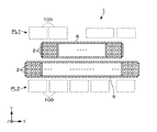
- FIG. 2 shows an example of a plot plan of the NG liquefaction apparatus 1.
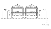
- a group of facilities (equipment groups PL1, PL2) constituting the NG liquefaction apparatus 1 are arranged and arranged with the pipe rack 6 interposed therebetween.
- equipment groups PL1 and PL2 as equipment for various impurity removal processes constituting the pretreatment unit 11 and as equipment for the precooling unit 14 and the liquefaction unit 12, a tower tank, a heat exchanger, and a moving equipment as static equipment are used.
- a certain pump is provided.
- the broken line in FIG. 2 indicates the arrangement area 100 of these facilities.
- each pipe rack 6 is configured as an elongated rectangular frame structure as viewed from the upper surface side, and NG and various refrigerants (liquefied refrigerant and precooled refrigerant) exchanged between the devices constituting the above-described equipment groups PL1 and PL2. And a plurality of pipes 61 (an aggregate of the pipes 61) through which a fluid flows.
- refrigerants liquefied refrigerant and precooled refrigerant
- the number of ACHEs 2 provided in the pre-cooling refrigerant cycle 141 and the refrigerant cooling cycle 142 is large, and a condenser, a subcooler, a condenser, or the like may be configured using several to several tens of ACHEs 2. is there. For this reason, depending on the scale, there is an NG liquefaction apparatus 1 equipped with nearly 100 ACHEs 2 as a whole.
- the NG liquefaction apparatus 1 of the present example is configured such that, for example, three ACHEs 2 are arranged on the upper surface of a rectangular pipe rack 6 as viewed from the upper surface side along the short side direction of the rectangle to form a set. A large number of these sets of ACHE2 are arranged along the long side direction of the rectangle.
- FIG. 4 shows a configuration example of the suction-type ACHE 2.
- the ACHE 2 is a bundle of a large number of tubes 23 through which a fluid to be cooled (a fluid handled by the NG liquefaction apparatus 1: a liquefied refrigerant, a precooled refrigerant, and other fluids handled in the process of the pretreatment unit 11) flows. It includes a tube bundle 230 and the fan 22 disposed above the tube bundle 230.
- the tube bundle 230 is open on both upper and lower surfaces, and allows cooling air to flow upward from below through the gap between the adjacent tubes 23. Further, a frame constituting a side peripheral portion of the tube bundle 230 is fixed to an upper surface of a frame constituting the pipe rack 6.
- the fan 22 includes a plurality of blades 220 provided to extend radially from the center of rotation.
- the base end of each rotor blade 220 is connected to the upper end of the rotating shaft 222 at the center of rotation, and the rotating shaft 222 is arranged to extend in the vertical direction.
- the lower side of the rotating shaft 222 penetrates the tube bundle 230, and the lower end thereof is connected to a rotation driving unit 221 disposed below the tube bundle 230.
- the drive belt 225 may be wound around the motor pulley 224 on the side, and the rotating shaft 222 may be rotated via the drive belt 225. Further, the rotating shaft 222 may be directly connected to the rotating motor.
- a duct 21 is provided as an exhaust path for passing air that has passed through the tube bundle 230.
- the duct 21 is open toward the upper surface at a position above the fan 22.
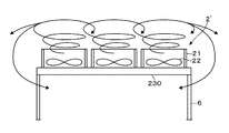
- the energy supplied by rotating the fan 22 mainly takes in cooling air from the lower surface of the tube bundle 230, passes through the gaps between a number of tubes 23, and opens the opening on the upper surface side of the duct 21. It is consumed to form a pressure difference (equivalent energy for static pressure) and to form a flow of cooling air (energy for dynamic pressure) until the gas is discharged.
- the inventor of the present application has understood that, of the entire energy supplied from the fan 22, the above-described static pressure energy consumption is about 70%, and the dynamic pressure energy consumption is about 10%. Therefore, it can be said that the remaining 20% of the energy is not used for forming a pressure difference between the inlet and the outlet of the ACHE 2 '(ie, increasing the pressure) or forming a flow.
- the inventor has found that the energy consumed without contributing to the cooling capacity of the ACHE 2 ′ is consumed by the formation of a swirling flow due to the rotation of the fan 22 and the turbulent dissipation.
- the ACHE 2 of the present application is provided with a configuration capable of converting the energy lost for the formation of the swirl flow into the pressurization of the cooling air and the formation of the flow by suppressing the formation of the swirl flow. .
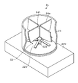
- the ACHE 2 of the present example includes a stationary blade 24 that rectifies a swirling flow formed by the fan 22 into a vertical flow.
- the stationary blade 24 can be exemplified by a configuration in which a plurality of flat plates are arranged in the duct 21 in a region above the fan 22. As shown in FIG. 5, the plurality of stationary blades 24 are provided so as to radially spread from the center position of the duct 21 in plan view toward the inner wall surface of the duct 21.
- a support shaft 241 is arranged above the rotation shaft 222 of the fan 22 along the direction in which the rotation shaft 222 extends (vertical direction), and the outer peripheral surface of the support shaft 241 and the inner periphery of the duct 21.
- Each stationary blade 24 is held so as to connect with the surface.
- H / D which is the ratio of the height H from the upper end position of the fan to the opening of the duct shown in FIG.
- H / D the value of H from the upper end position of the fan to the opening of the duct shown in FIG.
- the value of H / D can be in the range of 0.1 to 1.5.
- the number of the stationary blades 24 is preferably in the range of 2 to 8.
- the height of the duct 21 whose base position is the connection position to the pipe rack 6 (tube bundle 230) may be in the range of about 1 to 15 m.
- the number of the stationary blades 24 and the number of the moving blades 220 of the fan 22 are different.
- FIGS. 5 and 6 show examples in which the number of moving blades 220 provided on the fan 22 is larger than the number of stationary blades 24 installed.
- the number of stationary blades 24 is more preferably different from the divisor of the number of rotor blades 220.
- the number of the moving blades 220 is six, so the number of the stationary blades 24 is four, which is different from the divisor (3, 2) of the number of the moving blades 220.
- the fan 22 of the ACHE 2 shown in FIG. 6 has four moving blades 220, and thus the number of stationary blades 24 is three different from the divisor (2) of the number of moving blades 220. .
- the vertical flow velocity of the cooling air discharged from the opening of the duct 21 is preferably a value within a range of 5 to 20 m / s. Therefore, as described above, when two to eight vanes 24 are installed with the H / D value in the range of 0.1 to 1.5, the vertical velocity of the cooling air further decreases by 5 to 5.
- the number of stationary blades 24 to be installed may be selected so as to be a value within the range of 20 m / s.
- the flow rate of the cooling air at the opening of the duct 21 when the number of the stationary blades 24 is changed can be specified by CFD (Computational Fluid Dynamics).
- the stationary blades 24 may be installed not only when installing the ACHE 2 having the stationary blades 24 but also by modifying the ACHE 2 ′ provided in the existing NG liquefaction apparatus 1. Can be. For the ACHE 2 'already provided with the duct 21, only the stationary blade 24 may be additionally installed. Further, for the ACHE 2 ′ which does not include the duct 21 or has insufficient height and strength of the duct 21, the vane 24 may be installed together with replacement and modification of the duct 21.
- the following effects are obtained. Since the support shaft 241 for rectifying the swirling flow into a vertical flow is provided in the duct 21 above the fan 22 of the ACHE 2 provided in the NG liquefaction apparatus, the energy loss caused by the generation of the swirling flow is suppressed. In addition, it is possible to suppress a decrease in the air volume of the cooling air.
- the configuration of the support shaft 241 is not limited to the case where a flat plate is used as in the example described with reference to FIGS.
- a plate member curved so that the inclination with respect to the horizontal direction gradually increases from the lower end to the upper end along the rotation direction of the fan 22 may be provided.
- the inclination with respect to the horizontal direction can be adjusted within the range of 30 to 90 ° C. (vertical). By gradually rectifying the flow of the swirling flow into a vertical flow, it is possible to suppress an increase in noise and turbulent dissipation.
- the natural gas processing apparatus using the ACHE 2 provided with the stationary blades 24, 24a is not limited to the example of the NG liquefaction apparatus 1 shown in FIGS. 1 (a) and 1 (b).
- liquids heavier than ethane, including condensate, are recovered from NG, and gases lighter than methane are shipped to customers in gaseous form without liquefaction or consumed as fuel gas in factories.
- the stationary blades 24 and 24a may be provided in parallel with the ACHE 2 provided in a natural gas (Liquids) apparatus.
Landscapes
- Engineering & Computer Science (AREA)
- Physics & Mathematics (AREA)
- Thermal Sciences (AREA)
- Mechanical Engineering (AREA)
- General Engineering & Computer Science (AREA)
- Separation By Low-Temperature Treatments (AREA)
Abstract
Le problème décrit par la présente invention est de pourvoir à une technique permettant de supprimer une réduction de l'écoulement d'air d'un échangeur de chaleur refroidi par air agencé dans un appareil de traitement de gaz naturel. La solution selon l'invention concerne un appareil (1) de traitement de gaz naturel comprenant un échangeur de chaleur (2) refroidi par air comportant : un faisceau (230) de tubes dans lequel des tubes (23), à travers lesquels circule un fluide à refroidir, sont groupés, le fluide à refroidir étant un fluide manipulé lors du traitement du gaz naturel ; un ventilateur (22) destiné à alimenter en air de refroidissement le faisceau (230) de tubes ; et un conduit (21) formant un passage d'échappement pour le fluide de refroidissement. Une aube (24) de stator, destinée à redresser un écoulement tourbillonnant formé par un ventilateur (11) afin de former un écoulement dans la direction verticale, est agencée à l'intérieur du conduit (21) au-dessus du ventilateur (22) de l'échangeur de chaleur (2) refroidi par air.
Priority Applications (1)
| Application Number | Priority Date | Filing Date | Title |
|---|---|---|---|
| PCT/JP2018/027992 WO2020021668A1 (fr) | 2018-07-25 | 2018-07-25 | Appareil de traitement de gaz naturel |
Applications Claiming Priority (1)
| Application Number | Priority Date | Filing Date | Title |
|---|---|---|---|
| PCT/JP2018/027992 WO2020021668A1 (fr) | 2018-07-25 | 2018-07-25 | Appareil de traitement de gaz naturel |
Publications (1)
| Publication Number | Publication Date |
|---|---|
| WO2020021668A1 true WO2020021668A1 (fr) | 2020-01-30 |
Family
ID=69181506
Family Applications (1)
| Application Number | Title | Priority Date | Filing Date |
|---|---|---|---|
| PCT/JP2018/027992 Ceased WO2020021668A1 (fr) | 2018-07-25 | 2018-07-25 | Appareil de traitement de gaz naturel |
Country Status (1)
| Country | Link |
|---|---|
| WO (1) | WO2020021668A1 (fr) |
Citations (8)
| Publication number | Priority date | Publication date | Assignee | Title |
|---|---|---|---|---|
| JPS5029629U (fr) * | 1973-07-11 | 1975-04-03 | ||
| JPS61502267A (ja) * | 1984-05-23 | 1986-10-09 | エアフロ−・リサ−チ・アンド・マニュファクチュアリング・コ−ポレ−ション | ファン及びハウジング |
| US5066194A (en) * | 1991-02-11 | 1991-11-19 | Carrier Corporation | Fan orifice structure and cover for outside enclosure of an air conditioning system |
| JP2000205194A (ja) * | 1998-12-31 | 2000-07-25 | Halla Aircon Co Ltd | 軸流ファン用案内羽及びその案内羽を備える軸流ファンシュラウド組立体 |
| JP2003294269A (ja) * | 2002-04-01 | 2003-10-15 | Takasago Thermal Eng Co Ltd | 室外機の配置システム |
| JP2006214419A (ja) * | 2005-02-07 | 2006-08-17 | Sanyo Denki Co Ltd | 軸流送風機 |
| CN102374801A (zh) * | 2010-08-23 | 2012-03-14 | 李宁 | 驭风空冷塔 |
| WO2017125965A1 (fr) * | 2016-01-21 | 2017-07-27 | 日揮株式会社 | Dispositif de traitement de gaz naturel |
-
2018
- 2018-07-25 WO PCT/JP2018/027992 patent/WO2020021668A1/fr not_active Ceased
Patent Citations (8)
| Publication number | Priority date | Publication date | Assignee | Title |
|---|---|---|---|---|
| JPS5029629U (fr) * | 1973-07-11 | 1975-04-03 | ||
| JPS61502267A (ja) * | 1984-05-23 | 1986-10-09 | エアフロ−・リサ−チ・アンド・マニュファクチュアリング・コ−ポレ−ション | ファン及びハウジング |
| US5066194A (en) * | 1991-02-11 | 1991-11-19 | Carrier Corporation | Fan orifice structure and cover for outside enclosure of an air conditioning system |
| JP2000205194A (ja) * | 1998-12-31 | 2000-07-25 | Halla Aircon Co Ltd | 軸流ファン用案内羽及びその案内羽を備える軸流ファンシュラウド組立体 |
| JP2003294269A (ja) * | 2002-04-01 | 2003-10-15 | Takasago Thermal Eng Co Ltd | 室外機の配置システム |
| JP2006214419A (ja) * | 2005-02-07 | 2006-08-17 | Sanyo Denki Co Ltd | 軸流送風機 |
| CN102374801A (zh) * | 2010-08-23 | 2012-03-14 | 李宁 | 驭风空冷塔 |
| WO2017125965A1 (fr) * | 2016-01-21 | 2017-07-27 | 日揮株式会社 | Dispositif de traitement de gaz naturel |
Similar Documents
| Publication | Publication Date | Title |
|---|---|---|
| CN1122807C (zh) | 液化天然气的设备 | |
| BRPI0904895A2 (pt) | sistema de liquefação de gás natural, método para liquefação de gás natural, e sistema de liquefação de gás natural para plantas de liquefação de grande capacidade | |
| JP6725571B2 (ja) | ダブルフロー圧縮器を用いたlngプラントにおける並列圧縮 | |
| BR112019017533A2 (pt) | Sistema liquidificante de gás natural, e, método. | |
| WO2016001952A1 (fr) | Installation de production de gaz liquéfié de type à refroidissement par air | |
| JP6360987B1 (ja) | 天然ガス液化装置、及び天然ガス液化装置の設計方法 | |
| WO2017175384A1 (fr) | Appareil de traitement de gaz | |
| RU2747868C1 (ru) | Модуль для устройства сжижения природного газа и устройство сжижения природного газа | |
| US11162746B2 (en) | Liquid drains in core-in-shell heat exchanger | |
| US10935312B2 (en) | Balancing power in split mixed refrigerant liquefaction system | |
| RU2665015C1 (ru) | Установка для сжижения газа | |
| US11747081B2 (en) | Method and system for efficient nonsynchronous LNG production using large scale multi-shaft gas turbines | |
| US11913717B2 (en) | Natural gas liquefying apparatus | |
| JP7313459B2 (ja) | 天然ガス液化装置 | |
| WO2019159371A1 (fr) | Liquéfacteur de gaz naturel | |
| WO2017125965A1 (fr) | Dispositif de traitement de gaz naturel | |
| JP2020159647A (ja) | 天然ガス液化装置 | |
| CA3150438A1 (fr) | Procede et systeme d'echangeur de chaleur | |
| AU2017419936A1 (en) | Natural gas liquefaction device | |
| WO2020075295A1 (fr) | Dispositif de liquéfaction de gaz naturel | |
| BR112020005256A2 (pt) | sistema de refrigerante misto e método |
Legal Events
| Date | Code | Title | Description |
|---|---|---|---|
| 121 | Ep: the epo has been informed by wipo that ep was designated in this application |
Ref document number: 18927359 Country of ref document: EP Kind code of ref document: A1 |
|
| NENP | Non-entry into the national phase |
Ref country code: DE |
|
| 122 | Ep: pct application non-entry in european phase |
Ref document number: 18927359 Country of ref document: EP Kind code of ref document: A1 |