WO2020021720A1 - ユーザ端末 - Google Patents
ユーザ端末 Download PDFInfo
- Publication number
- WO2020021720A1 WO2020021720A1 PCT/JP2018/028325 JP2018028325W WO2020021720A1 WO 2020021720 A1 WO2020021720 A1 WO 2020021720A1 JP 2018028325 W JP2018028325 W JP 2018028325W WO 2020021720 A1 WO2020021720 A1 WO 2020021720A1
- Authority
- WO
- WIPO (PCT)
- Prior art keywords
- dci
- index
- user terminal
- cce
- resource
- Prior art date
- Legal status (The legal status is an assumption and is not a legal conclusion. Google has not performed a legal analysis and makes no representation as to the accuracy of the status listed.)
- Ceased
Links
Images


Classifications
-
- H—ELECTRICITY
- H04—ELECTRIC COMMUNICATION TECHNIQUE
- H04L—TRANSMISSION OF DIGITAL INFORMATION, e.g. TELEGRAPHIC COMMUNICATION
- H04L1/00—Arrangements for detecting or preventing errors in the information received
- H04L1/12—Arrangements for detecting or preventing errors in the information received by using return channel
- H04L1/16—Arrangements for detecting or preventing errors in the information received by using return channel in which the return channel carries supervisory signals, e.g. repetition request signals
- H04L1/18—Automatic repetition systems, e.g. Van Duuren systems
- H04L1/1829—Arrangements specially adapted for the receiver end
- H04L1/1854—Scheduling and prioritising arrangements
-
- H—ELECTRICITY
- H04—ELECTRIC COMMUNICATION TECHNIQUE
- H04W—WIRELESS COMMUNICATION NETWORKS
- H04W72/00—Local resource management
- H04W72/50—Allocation or scheduling criteria for wireless resources
- H04W72/53—Allocation or scheduling criteria for wireless resources based on regulatory allocation policies
-
- H—ELECTRICITY
- H04—ELECTRIC COMMUNICATION TECHNIQUE
- H04L—TRANSMISSION OF DIGITAL INFORMATION, e.g. TELEGRAPHIC COMMUNICATION
- H04L1/00—Arrangements for detecting or preventing errors in the information received
- H04L1/12—Arrangements for detecting or preventing errors in the information received by using return channel
- H04L1/16—Arrangements for detecting or preventing errors in the information received by using return channel in which the return channel carries supervisory signals, e.g. repetition request signals
- H04L1/18—Automatic repetition systems, e.g. Van Duuren systems
- H04L1/1867—Arrangements specially adapted for the transmitter end
- H04L1/1896—ARQ related signaling
-
- H—ELECTRICITY
- H04—ELECTRIC COMMUNICATION TECHNIQUE
- H04L—TRANSMISSION OF DIGITAL INFORMATION, e.g. TELEGRAPHIC COMMUNICATION
- H04L5/00—Arrangements affording multiple use of the transmission path
- H04L5/003—Arrangements for allocating sub-channels of the transmission path
- H04L5/0053—Allocation of signalling, i.e. of overhead other than pilot signals
-
- H—ELECTRICITY
- H04—ELECTRIC COMMUNICATION TECHNIQUE
- H04W—WIRELESS COMMUNICATION NETWORKS
- H04W72/00—Local resource management
- H04W72/04—Wireless resource allocation
- H04W72/044—Wireless resource allocation based on the type of the allocated resource
- H04W72/0446—Resources in time domain, e.g. slots or frames
-
- H—ELECTRICITY
- H04—ELECTRIC COMMUNICATION TECHNIQUE
- H04W—WIRELESS COMMUNICATION NETWORKS
- H04W72/00—Local resource management
- H04W72/20—Control channels or signalling for resource management
- H04W72/23—Control channels or signalling for resource management in the downlink direction of a wireless link, i.e. towards a terminal
-
- H—ELECTRICITY
- H04—ELECTRIC COMMUNICATION TECHNIQUE
- H04L—TRANSMISSION OF DIGITAL INFORMATION, e.g. TELEGRAPHIC COMMUNICATION
- H04L5/00—Arrangements affording multiple use of the transmission path
- H04L5/0001—Arrangements for dividing the transmission path
- H04L5/0003—Two-dimensional division
- H04L5/0005—Time-frequency
- H04L5/0007—Time-frequency the frequencies being orthogonal, e.g. OFDM(A) or DMT
- H04L5/001—Time-frequency the frequencies being orthogonal, e.g. OFDM(A) or DMT the frequencies being arranged in component carriers
Definitions
- the present invention relates to a user terminal in a next-generation mobile communication system.
- LTE Long Term Evolution
- LTE-A LTE Advanced, LTE @ Rel. 10, 11, 12, 13
- LTE @ Rel. 8, 9 LTE @ Rel. 8, 9
- a user terminal transmits a downlink shared channel (eg, a downlink shared channel scheduled by downlink control information (DCI: Downlink @ Control @ Information)).
- PDSCH Physical Downlink Shared Channel
- the user terminal performs uplink control on uplink control information (UCI: Uplink Control Information) including acknowledgment information (HARQ-ACK: Hybrid Automatic Repeat Repeat reQuest-ACKnowledge, ACK / NACK: ACKnowledge / Non-ACK) for the downlink shared channel.
- UCI Uplink Control Information
- HARQ-ACK Hybrid Automatic Repeat Repeat reQuest-ACKnowledge, ACK / NACK: ACKnowledge / Non-ACK
- Transmission is performed using a channel (for example, PUCCH: Physical Uplink Control Channel) or an uplink shared channel (for example, PUSCH: Physical Uplink Shared Channel).
- E-UTRA Evolved Universal Terrestrial Radio Access
- E-UTRAN Evolved Universal Terrestrial Radio Access Network
- a user terminal is used for transmitting UCI including delivery acknowledgment information (for example, HARQ-ACK, ACK / NACK) of a downlink shared channel (for example, PDSCH).
- a resource for an uplink control channel (for example, a PUCCH resource) is determined based on a value of a predetermined field (a PUCCH resource identifier (PRI: PUCCH @ resource @ indicator / indication) field or the like) in DCI for scheduling the downlink shared channel. It is considered to be.
- a PUCCH resource identifier PRI: PUCCH @ resource @ indicator / indication
- a plurality of DCIs indicating that HARQ-ACK is fed back using the same PUCCH are detected in at least one of the time domain and the frequency domain (eg, at least one of the plurality of slots and the plurality of cells).
- the resources for the uplink control channel cannot be appropriately determined, there is a possibility that the error rate of the uplink control channel may increase.
- the present invention has been made in view of such a point, and it is an object of the present invention to provide a user terminal capable of appropriately determining an uplink control channel resource.
- One aspect of the user terminal of the present invention receives a plurality of downlink control information (DCI) each including a predetermined field value indicating the same slot for an uplink control channel used for transmitting acknowledgment information for a plurality of downlink shared channels. And a control unit that controls derivation of an index of a control channel element (CCE) used for determining resources for the uplink control channel.
- DCI downlink control information
- CCE control channel element
- resources for the uplink control channel can be appropriately determined.
- FIG. 1 is a diagram illustrating an example of an association between a PRI and a PUCCH resource set by higher layer signaling.
- 2A and 2B are diagrams illustrating an example of PUCCH resource determination.
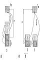
- FIG. 3 is a diagram illustrating an example of PUCCH resource determination when a plurality of DCIs are detected in the frequency domain according to the first example.
- FIG. 4 is a diagram illustrating another example of PUCCH resource determination when a plurality of DCIs are detected in the frequency domain according to the first example.
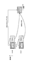
- FIG. 5 is a diagram illustrating an example of PUCCH resource determination when a plurality of DCIs are detected in the time domain according to the first example.
- FIG. 1 is a diagram illustrating an example of an association between a PRI and a PUCCH resource set by higher layer signaling.
- 2A and 2B are diagrams illustrating an example of PUCCH resource determination.
- FIG. 3 is a diagram illustrating an example of PUCCH resource determination when a plurality
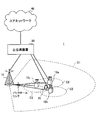
- FIG. 6 is a diagram illustrating an example of a schematic configuration of the wireless communication system according to the present embodiment.
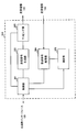
- FIG. 7 is a diagram showing an example of the overall configuration of the radio base station according to the present embodiment.
- FIG. 8 is a diagram showing an example of a functional configuration of the radio base station according to the present embodiment.
- FIG. 9 is a diagram showing an example of the overall configuration of the user terminal according to the present embodiment.
- FIG. 10 is a diagram illustrating an example of a functional configuration of the user terminal according to the present embodiment.
- FIG. 11 is a diagram illustrating an example of a hardware configuration of the radio base station and the user terminal according to the present embodiment.
- PUCCH format In NR, a configuration (also referred to as a format, a PUCCH format (PF), etc.) for an uplink control channel (for example, PUCCH) used for transmitting uplink control information (UCI: Uplink Control Information) is being studied.
- PUCCH Physical Uplink Control Channel
- the UCI is acknowledgment information (HARQ-ACK: Hybrid Automatic Repeat Repeat reQuest-ACKnowledge, ACK / NACK: ACKnowledge / Non-ACK) for a downlink shared channel (for example, PDSCH: Physical Downlink Shared Channel), scheduling request (SR : Scheduling Request) and channel state information (CSI: Channel State Information).
- HARQ-ACK Hybrid Automatic Repeat Repeat reQuest-ACKnowledge
- ACK / NACK ACKnowledge / Non-ACK
- CSI Channel State Information
- a PUCCH format (also referred to as PF0, short PUCCH, etc.) used for transmitting 1 or 2 bit UCI (for example, at least one of HARQ-ACK and SR) and transmitted with 1 or 2 symbols;
- a PUCCH format (also referred to as PF1, long PUCCH, etc.) used for transmitting 1 or 2 bit UCI (for example, at least one of HARQ-ACK and SR) and transmitted with 4 symbols or more.
- PUCCH format (also referred to as PF2, short PUCCH, etc.) used for transmitting UCI larger than 2 bits and transmitted in 1 or 2 symbols
- PUCCH format (also called PF3, long PUCCH, etc.) used for transmitting UCI larger than 2 bits and transmitted with 4 symbols or more
- a PUCCH format (also referred to as PF4, long PUCCH, or the like) that is used for transmitting a UCI larger than 2 bits, is transmitted in 4 symbols or more, and includes a PUCCH resource including an orthogonal cover code (OCC).
- OCC orthogonal cover code
- the PUCCH in the PUCCH format described above may be transmitted in a specific cell in a group including one or more cells (also referred to as a cell group (CG: Cell @ Group), a PUCCH group, or the like).
- the specific cell may be, for example, a primary cell (PCCell: Primary @ Cell), a primary secondary cell (PSCell: Primary @ Secondary @ Cell), a secondary cell for PUCCH transmission (SCell: Secondary @ Cell, PUCCH-SCell), or the like.
- the “cell” may be reworded as a serving cell, a component carrier (CC: Component @ Carrier), a carrier, or the like.
- a set of one or more PUCCH resources may be configured by higher layer signaling.
- the setting by higher layer signaling refers to a setting from a base station (BS (Base Station), a transmission / reception point (TRP: Transmission / Reception Point), eNB (eNodeB), gNB (NR NodeB), or the like) to a user terminal (UE (UE)).
- BS Base Station
- TRP Transmission / Reception Point
- eNB eNodeB
- gNB NR NodeB
- UE user terminal
- UE User Equipment
- MS Mobile station
- the upper layer signaling may be, for example, at least one of the following: RRC (Radio Resource Control) signaling, MAC (Medium Access Control) signaling (eg, MAC CE (Control Element), MAC PDU (Protocol Data Unit)), Information transmitted by a broadcast channel (for example, PBCH: Physical Broadcast Channel) (for example, a master information block (MIB)); System information (for example, system information block (SIB: System Information Block), minimum system information (RMSI: Remaining Minimum System Information), and other system information (OSI: Other System Information)).
- RRC Radio Resource Control
- MAC Medium Access Control
- MAC CE Control Element
- MAC PDU Protocol Data Unit
- Information transmitted by a broadcast channel for example, PBCH: Physical Broadcast Channel
- MIB master information block
- SIB System Information Block
- SIB System Information Block
- RMSI Remaining Minimum System Information
- OSI Other System Information
- a set including one or more PUCCH resources may be set by higher layer signaling for each partial band (bandwidth part (BWP: Bandwidth @ Part)) set in the CC. .
- BWP Bandwidth @ Part
- One or more PUCCH resource sets may be set in the user terminal.
- the user terminal may determine one of the set PUCCH resource sets based on the number of bits (payload) of the UCI.
- N 2 and N 3 respectively, a predetermined threshold may be set by higher layer signaling.
- the user terminal determines a predetermined field (PUCCH resource identifier (PRI: PUCCH @ resource @ indicator / indication) field, ACK / NACK resource identifier (ARI: ACK / NACK) in the DCI.
- PUCCH resource identifier PRI: PUCCH @ resource @ indicator / indication
- ACK / NACK resource identifier ARI: ACK / NACK
- a PUCCH resource used for transmission of the UCI may be determined based on a value of a Resource @ Indicator field, an ACK / NACK resource offset (ARO: ACK / NACK @ Resource @ Offset) field, or the like).
- the value of the predetermined field is also called PRI, ARI, ARO, or the like.
- each PUCCH resource in the PUCCH resource set may be associated with each value (also referred to as PRI) of a PRI field in DCI.
- the DCI may be a DCI (DL assignment, DCI format 1_0 or 1_1) used for PDSCH scheduling.
- FIG. 1 is a diagram showing an example of association between a PRI and a PUCCH resource set by higher layer signaling.
- the eight types of values are the first to eighth of the list (ResourceList) of a maximum of eight PUCCH resources in the PUCCH resource set, respectively. It may be mapped to the first to eighth PUCCH resources identified by an identifier (PUCCH resource ID) obtained from the value.
- PUCCH resource ID an identifier
- a PUCCH resource for UCI transmission may be determined based on other parameters.
- Such other parameters may include at least one of the following: A control channel element (CCE: Control Channel Element) in a control resource set (CRESET: Control Resource Set) p for receiving a downlink control channel (eg, PDCCH: Physical Downlink Control Channel) for transmitting a DCI including a PRI field; Number (N CCE, p ), An index (n CCE, p , CCE index) of a CCE for reception of the downlink control channel (for example, the first CCE).
- CCE Control Channel Element
- CRESET Control Resource Set
- the user terminal when the PRI field in DCI is 3 bits, if the number of PUCCH resources in the PUCCH resource set (the size of the list (ResourceList), also called R PUCCH, etc.) is larger than 8, the user terminal becomes: 1, PUCCH resources (index r PUCCH ) used for UCI transmission may be determined.
- the number of PUCCH resources in the PUCCH resource set (the size of the list (ResourceList), also called R PUCCH, etc.) is larger than 8
- the user terminal becomes: 1, PUCCH resources (index r PUCCH ) used for UCI transmission may be determined.
- N CCE, p is the number of CCEs in CORESETp corresponding to PDCCH reception in DCI (for example, DCI format 1_0 or 1_1).
- n CCE, p is the index of the first CCE for PDCCH reception (the minimum index of the CCE in the PDCCH candidate where DCI is detected).
- ⁇ PRI is the value of the PRI field in DCI (for example, DCI format 1_0 or 1_1).
- R PUCCH is the number of PUCCH resources included in the PUCCH resource set.
- Each PUCCH resource includes, for example, the number of symbols allocated to the PUCCH, the start index of the symbol, the resource block (also referred to as a physical resource block (PRB)) allocated to the PUCCH, the start index of the resource block, It may include at least one of whether to apply frequency hopping in a slot, a start index of a PRB of a second hop when frequency hopping is applied, and the like.
- the resource block also referred to as a physical resource block (PRB) allocated to the PUCCH
- PRB physical resource block
- each PUCCH resource is associated with the PUCCH format, and may include associated PUCCH format-specific resources (eg, initial cyclic shift of PF0, OCC in the time domain of PF1, OCC length of PF4, OCC index, etc.). Good.
- the user terminal when a plurality of PDSCHs are scheduled by a plurality of DCIs (for example, DCI format 1_0 or 1_1), the user terminal transmits UCI including HARQ-ACK corresponding to the plurality of PDSCHs in the same slot. It is also assumed that the same PUCCH is used to feed back to the base station.
- DCI format 1_0 or 1_1 DCI format 1_0 or 1_1
- a predetermined field (also referred to as a PDSCH-to-HARQ_feedback ⁇ timing ⁇ indicator ⁇ field, an HARQ feedback timing indication field, an HARQ-ACK timing indication field, etc.) in the plurality of DCIs is a HARQ for the PDSCH scheduled by the plurality of DCIs.
- a same slot may be indicated for PUCCH used for ACK transmission.
- the user terminal It is important to determine which DCI to use to determine the PUCCH resource used for transmitting the UCI.
- “different time domain resources” may be, for example, different slots, different symbols, and the like.
- the “different frequency domain resources” may be, for example, a plurality of different cells (also referred to as CCs, carriers, serving cells, etc.), or different partial bands (BWP: BandWidth: Part)).
- the cell index is also called a cell index, a CC index, a carrier index, or the like.
- the BWP index is also called a BWP index or the like.
- FIGS. 2A and 2B are diagrams illustrating an example of PUCCH resource determination.
- a PRI field value in DCI is 3 bits, and a maximum of eight PUCCH resources are set in a PUCCH resource set (for example, a first PUCCH resource set) determined based on a UCI payload. Shall be included.
- the PUCCH is arranged in one entire slot, but the present invention is not limited to this, and any PUCCH format described above may be used.
- the user terminal determines the number of DCIs in the plurality of DCIs.
- the PUCCH resource may be determined based on the last (last) PRI in the DCI (for example, see FIG. 1).
- the user terminal sets the different cell index In between, the PUCCH resource may be determined based on the PRI in the DCI detected in the cell # 2 of the first cell index in descending order (descending (order) (for example, see FIG. 1).
- the user terminal when a plurality of DCIs for which HARQ-ACK is fed back using the same PUCCH are detected in at least one of different time domain resources and different frequency domain resources, the user terminal:
- the PRI used for PUCCH resource determination can be appropriately derived.
- a parameter other than the PRI for example, at least one of the CCE index and the number of CCEs in the RESET
- the user terminal uses the PUCCH resource.
- the PUCCH resource may not be properly determined.
- the present inventors studied a method of appropriately deriving a parameter other than the PRI (for example, at least one of the CCE index and the number of CCEs in the RESET) used for determining the PUCCH resource, and reached the present invention.
- a parameter other than the PRI for example, at least one of the CCE index and the number of CCEs in the RESET
- the present embodiment will be described in detail.
- the number of PUCCH resources included in the PUCCH resource set (for example, the first PUCCH resource set) determined based on the payload is larger than 2 to the power of x. It is assumed that it is large, but it is not limited to this.
- the present invention is applicable to any case of deriving PUCCH resources using parameters other than PRI.
- HARQ-ACK (2-bit HARQ-ACK) of PDSCH scheduled by 2DCI is fed back using the same PUCCH
- the present invention is not limited to this.
- This embodiment is also applicable to a case where two or more DCIs are received and a case where two or more bits of HARQ-ACK are fed back using the same PUCCH.
- the user terminal sets a CCE index used for PUCCH resource determination based on the frequency band index. You may decide.
- the frequency band is a cell
- the frequency band may be a serving cell, CC, carrier, BWP, or the like.
- cell index may be paraphrased as a serving cell index, a CC index, a carrier index, a BWP index, or the like.
- a CCE index used for PUCCH resource determination is in descending order among the plurality of cells. It may be derived from the DCI detected at the cell of the first cell index in (descending @ order) or ascending @ order.
- the “CCE index derived from the DCI” may be, for example, a CCE index of a predetermined CCE (first CCE) in which the DCI is arranged.
- the user terminal when detecting a plurality of DCIs indicating the same HARQ-ACK timing in a plurality of cells, the user terminal detects a cell in the descending first cell index (that is, the largest cell index).
- the PUCCH resource may be determined based on a CCE index derived from the obtained DCI.
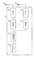
- FIG. 3 is a diagram showing an example of PUCCH resource determination when a plurality of DCIs are detected in the frequency domain according to the first example. For example, in FIG. 3, it is assumed that 2DCI including a HARQ-ACK timing field value indicating the same slot for PUCCH transmission is detected in cells # 1 and # 2 of the same slot.
- the user terminal determines a PUCCH resource used for transmitting a HARQ-ACK (for example, a 2-bit HARQ-ACK) for the 2PDSCH scheduled by the 2DCI.
- a HARQ-ACK for example, a 2-bit HARQ-ACK
- the user terminal sets the CCE index for DCI detected in cell # 2 of the first cell index in descending order among the 2DCI detected in cells # 1 and # 2, and the PRI in the DCI.
- the PUCCH resource may be determined. For determining the PUCCH resource, for example, Equation 1 above may be used.
- PRI and CCE indexes used for PUCCH resource determination are derived based on the same DCI. For this reason, in FIG. 3, the base station can easily allocate the CCE to the DCI and the PUCCH resource while considering the possibility of the DCI detection error.
- the user terminal can appropriately determine the PUCCH resource based on the PRI and the CCE index derived based on the DCI as long as the user terminal does not miss the detection of DCI in the cell with the largest cell index. . For this reason, when a user terminal uses an erroneous PUCCH resource, it is possible to prevent an increase in the PUCCH error rate due to collision with a PUCCH resource allocated to another user terminal.
- the user terminal when detecting a plurality of DCIs indicating the same HARQ-ACK timing in a plurality of cells, the user terminal detects the cells in the first cell index in ascending order (that is, the smallest cell index).
- the PUCCH resource may be determined based on a CCE index derived from the obtained DCI.
- FIG. 4 is a diagram showing another example of PUCCH resource determination when a plurality of DCIs are detected in the frequency domain according to the first example.
- FIG. 4 is different from FIG. 3 in that PUCCH resources are determined based on the CCE index for DCI detected in cell # 1 of the first cell index in ascending order, not in cell # 2 of the first cell index in descending order. different. The following description focuses on differences from FIG.
- the user terminal among the 2DCIs detected in cells # 1 and # 2, the CCE index for DCI detected in cell # 1 of the first index in ascending order and the first CCE index in descending order
- the PUCCH resource may be determined based on the PRI in DCI detected in cell # 2 of the index. For determining the PUCCH resource, for example, Equation 1 above may be used.
- a cell (cell # 1 in FIG. 3) of an ascending first cell index (that is, the smallest cell index) is a primary cell (PCell: It can be assumed that the connection cell is a connection cell with more stable communication quality, such as a Primary Cell or a Primary Secondary Cell (PSCell). Therefore, it can be expected that a cell having a smaller index value has a lower PDCCH error rate.
- PCell a connection cell with more stable communication quality, such as a Primary Cell or a Primary Secondary Cell (PSCell). Therefore, it can be expected that a cell having a smaller index value has a lower PDCCH error rate.
- the base station may arbitrarily set the PRI in the DCI transmitted in different cells in the same slot. Therefore, the base station can set the PRI in a plurality of DCIs transmitted in different cells in the same slot to the same value.
- the base station cannot always set the CCE in which the plurality of DCIs are arranged arbitrarily. For example, this is because another DCI cannot be allocated to a resource (eg, CCE) that collides with the DCI of another user terminal.
- a resource eg, CCE
- PUCCH resource can be appropriately determined based on the PRI and CCE index in the DCI to be performed.
- the user terminal In deriving the first and second CCE indexes, the user terminal recognizes a DCI detection error based on the value of a predetermined field (for example, a downlink assignment index (DAI) field) in each DCI. Is also good.
- a predetermined field for example, a downlink assignment index (DAI) field
- the bit value of the $ DAI field may indicate a value for counting a plurality of DCIs indicating the same HARQ-ACK timing (also referred to as a count value, a counter DAI (counter @ DAI), or the like).
- the user terminal may recognize at least some DCI detection errors based on the counter DAI in the plurality of DCIs and the preset number of DCIs in the cell direction (quasi-static). Code book (semi-static @ codebook)). For example, when the number of DCIs in the same slot in the cell direction is set to 2, the user terminal may recognize some DCI detection errors based on the missing counter DAI in the two DCIs.
- bit values for example, 2 most significant bits (MSB: Most Significant Bit)
- MSB Most Significant Bit
- LSB least significant Bit
- Bit may indicate the total number of the plurality of DCIs (also referred to as a total value, a total DAI (total DAI), etc.).
- the user terminal may recognize at least some DCI detection errors based on the counter DAI and the total DAI in the plurality of DCIs (dynamic codebook).
- FIGS. 3 and 4 show the counter DAI and the total DAI in two DCIs detected in cells # 1 and # 2 in the same slot.
- the user terminal recognizes a detection error of DCI for deriving a CCE index (for example, DCI transmitted in cell # 2 in FIG. 3, DCI transmitted in cell # 1 in FIG. 4). If so, for example, the PUCCH resource may be determined based on any of the following (1) to (3).
- the user terminal may assume that the CCE index used for determining the PUCCH resource is a fixed value (for example, zero). For determining the PUCCH resource, for example, Equation 1 above may be used.
- the user terminal may determine the PUCCH resource based on the ARI without using the CCE index.
- the user terminal may assume that the CCE index is zero, or may use an equation different from Equation 1 (for example, if the parameter n CCE, p for the CCCE index is Expressions excluded) may be used.
- the user terminal may determine the PUCCH resource based on a CCE index determined according to a predetermined rule in one or more actually detected DCIs.
- the CCE index determined according to the predetermined rule may be, for example, the CCE index of the first CCE in which the DCI of the first cell index in ascending or descending order is actually arranged among the DCIs actually detected.
- the PRI and CCE indexes are derived from the same DCI. In this case, if the detection of the DCI for deriving the CCE index is missed, the PRI may not be derivable. Further, in FIG. 4, even if the DCI for deriving the CCE index can be detected, the detection of the DCI for deriving the PRI may be missed.
- the base station may set the PRI in the DCI of different cells in the same slot to the same value.
- the user terminal may determine the PUCCH resource based on the PRI of another DCI actually detected.
- the PRI may be a PRI in the DCI of the first cell index in ascending or descending order among actually detected DCIs.
- the user terminal may determine the PUCCH resource on the assumption that the PRI is a fixed value (for example, zero).
- the user terminal receives a DCI (PDCCH) monitoring opportunity (also referred to as a monitoring period, a monitoring period, etc.) in addition to the cell index. Based on this, a CCE index used for PUCCH resource determination may be determined.
- a DCI DCI
- the user terminal determines whether the monitoring opportunity index (monitoring opportunity index)
- the CCE index may be determined based on the DCI detected at the monitoring opportunity of the first monitoring opportunity index in ascending or descending order.
- the user terminal detects the plurality of DCIs.
- the CCE index used for PUCCH resource determination may be determined based on the timing.
- the CCE index may be derived from the last DCI among a plurality of DCIs including a HARQ-ACK timing field value indicating the same slot for PUCCH transmission.
- the CCE index may be a CCE index of a predetermined CCE (first CCE) in which the last DCI is arranged.
- FIG. 5 is a diagram illustrating an example of PUCCH resource determination when a plurality of DCIs are detected in the time domain according to the first example.
- 2DCI including a HARQ-ACK timing field value indicating the same slot for PUCCH transmission is detected in different slots in the same cell.
- the description will focus on the differences from FIGS.
- the user terminal determines the PUCCH based on the PRI in the last DCI and the CCE index of the first CCE in which the DCI is located among the 2DCIs detected in different slots. Resources may be determined. For determining the PUCCH resource, for example, Equation 1 above may be used.
- the PUCCH resource index r PUCCH (0 ⁇ r PUCCH ⁇ R PUCCH ⁇ 1) is determined based on at least one of the following parameters.
- N CCE, p The number of CCEs (N CCE, p ) in the RESETp of the PDCCH reception of a predetermined DCI among DCIs having the HARQ-ACK timing field value indicating the same slot for PUCCH transmission; CCE index (n CCE, p ) of the first CCE of the PDCCH reception of the last DCI among the DCIs having the HARQ-ACK timing field value indicating the same slot for PUCCH transmission; PRI ( ⁇ PRI ) in the last DCI among the DCIs with the HARQ-ACK timing field value indicating the same slot for PUCCH transmission.
- the user terminal determines between the plurality of cell indexes of the last slot.
- the CCE index used for PUCCH resource determination may be derived based on the DCI detected in the cell in descending order or the first cell index.
- the CCE index used for PUCCH resource determination is appropriately determined. Can be derived. As a result, it is possible to appropriately determine the PUCCH resource used for transmitting the HARQ-ACK of the PDSCH scheduled in each of the plurality of DCIs.
- the number of CCEs in the coreset where the predetermined DCI is arranged is the number of CCEs in the search space (or a set of one or more search spaces (search space set)) in which the predetermined DCI is arranged. In other words, it may be paraphrased.
- the user terminal uses the DCI for deriving the CCE index or the PRI to perform
- the number of CCEs in CORESET may be derived, or the number of CCEs in CORESET may be derived based on a unique rule.
- the user terminal may determine the PUCCH resource based on the number of CCEs in the RESET where the DCI used for deriving the CCE index (n CCE, p ) is arranged.
- the user terminal derives a CCE index used for determining PUCCH resources based on DCI detected in the first cell # 2 in descending order of cell index. For this reason, the user terminal may determine the PUCCH resource based on the number of CCEs in the RESET where the DCI detected in the cell # 2 is allocated. In this case, all of the number of CCEs, the PRI, and the CCE index used for PUCCH resource determination may be derived based on the same DCI (DCI detected in cell # 2).
- the user terminal derives a CCE index used for determining a PUCCH resource based on DCI detected in the first cell # 1 in ascending cell index order. For this reason, the user terminal may determine the PUCCH resource based on the number of CCEs in the coreset where the DCI detected in cell # 1 is arranged. In this case, the number of CCEs and the CCE index used for determining the PUCCH resource are derived based on the same DCI (the DCI detected in cell # 2), and the PRI is determined by another DCI (the DCI detected in cell # 1). ) May be derived.
- the user terminal derives a CCE index used for determining PUCCH resources based on the last DCI. For this reason, the user terminal may determine the PUCCH resource based on the number of CCEs in the coreset where the last DCI is located. In this case, all of the number of CCEs, the PRI, and the CCE index used for determining the PUCCH resource may be derived based on the same DCI (the DCI detected in the last slot).
- the user terminal may determine the PUCCH resource based on the number of CCEs in the coreset where the DCI used for deriving the PRI is arranged.
- the PRI used for PUCCH resource determination is derived based on the DCI detected in the first cell # 2 in descending cell index order. Therefore, the user terminal may determine the PUCCH resource based on the number of CCEs in the COESET where the DCI detected in cell # 2 is allocated.
- the user terminal derives the PRI used for determining the PUCCH resource based on the last DCI. For this reason, the user terminal may determine the PUCCH resource based on the number of CCEs in the coreset where the last DCI is located.
- the user terminal may derive the number of CCEs based on a rule independent of at least one of the CCE index and the PRI, and determine the PUCCH resource based on the derived number of CCEs.
- the DCIs are derived from DCIs detected in the cell of the first cell index in descending or ascending order.
- the PUCCH resource may be determined based on the CCE index.
- PUCCH is determined based on a CCE index derived from the DCI detected in the first or last slot. Resources may be determined.
- the first cell in descending or ascending order among the DCIs of the cells detected in the first or last slot.
- the PUCCH resource may be determined based on the CCE index derived from the DCI detected in the cell of the index.
- the number of CCEs in the RESET used for PUCCH resource determination is determined. Can be appropriately derived. As a result, it is possible to appropriately determine the PUCCH resource used for transmitting the HARQ-ACK of the PDSCH scheduled in each of the plurality of DCIs.
- Wireless communication system Hereinafter, the configuration of the wireless communication system according to the present embodiment will be described. In this wireless communication system, communication is performed using at least one combination of the above aspects of the present disclosure.
- FIG. 6 is a diagram showing an example of a schematic configuration of the wireless communication system according to the present embodiment.
- carrier aggregation (CA) and / or dual connectivity (DC) in which a plurality of basic frequency blocks (component carriers) each having a unit of a system bandwidth (for example, 20 MHz) of an LTE system are applied. can do.
- DC dual connectivity
- the wireless communication system 1 includes LTE (Long Term Evolution), LTE-A (LTE-Advanced), LTE-B (LTE-Beyond), SUPER 3G, IMT-Advanced, 4G (4th generation mobile communication system), and 5G. (5th generation mobile communication system), NR (New Radio), FRA (Future Radio Access), New-RAT (Radio Access Technology), etc., or a system for realizing these.
- LTE Long Term Evolution
- LTE-A LTE-Advanced
- LTE-B LTE-Beyond
- SUPER 3G IMT-Advanced
- 4G 4th generation mobile communication system
- 5G 5th generation mobile communication system
- NR New Radio
- FRA Full Radio Access
- New-RAT Radio Access Technology
- the radio communication system 1 includes a radio base station 11 forming a macro cell C1 having relatively wide coverage, and a radio base station 12 (12a to 12c) arranged in the macro cell C1 and forming a small cell C2 smaller than the macro cell C1. , Is provided. Further, user terminals 20 are arranged in the macro cell C1 and each small cell C2. The arrangement, number, and the like of each cell and the user terminals 20 are not limited to the modes shown in the figure.
- the user terminal 20 can be connected to both the radio base station 11 and the radio base station 12. It is assumed that the user terminal 20 uses the macro cell C1 and the small cell C2 simultaneously using CA or DC. Further, the user terminal 20 may apply CA or DC using a plurality of cells (CC).
- CC a plurality of cells
- Communication between the user terminal 20 and the radio base station 11 can be performed using a carrier having a relatively low frequency band (for example, 2 GHz) and a narrow bandwidth (also referred to as an existing carrier or a legacy carrier).
- a carrier having a relatively high frequency band for example, 3.5 GHz, 5 GHz or the like
- a wide bandwidth may be used between the user terminal 20 and the radio base station 12, The same carrier as that between may be used.
- the configuration of the frequency band used by each wireless base station is not limited to this.
- the user terminal 20 can perform communication using time division duplex (TDD: Time Division Duplex) and / or frequency division duplex (FDD: Frequency Division Duplex) in each cell.
- TDD Time Division Duplex
- FDD Frequency Division Duplex
- a single numerology may be applied, or a plurality of different numerologies may be applied.
- Numerology may be a communication parameter applied to transmission and / or reception of a certain signal and / or channel, for example, subcarrier interval, bandwidth, symbol length, cyclic prefix length, subframe length. , TTI length, number of symbols per TTI, radio frame configuration, specific filtering processing performed by the transceiver in the frequency domain, specific windowing processing performed by the transceiver in the time domain, and the like.
- the numerology may be referred to as different.
- the wireless base station 11 and the wireless base station 12 are connected by wire (for example, an optical fiber compliant with CPRI (Common Public Radio Interface) or an X2 interface) or wirelessly. May be done.
- the wireless base station 11 and each wireless base station 12 are connected to the upper station device 30 and are connected to the core network 40 via the upper station device 30.
- the higher station apparatus 30 includes, for example, an access gateway apparatus, a radio network controller (RNC), a mobility management entity (MME), and the like, but is not limited thereto.
- RNC radio network controller
- MME mobility management entity
- each wireless base station 12 may be connected to the upper station device 30 via the wireless base station 11.
- the radio base station 11 is a radio base station having relatively wide coverage, and may be called a macro base station, an aggregation node, an eNB (eNodeB), a transmission / reception point, or the like.
- the radio base station 12 is a radio base station having local coverage, and includes a small base station, a micro base station, a pico base station, a femto base station, a HeNB (Home eNodeB), an RRH (Remote Radio Head), and transmission / reception. It may be called a point.
- the wireless base stations 11 and 12 are not distinguished, they are collectively referred to as a wireless base station 10.
- Each user terminal 20 is a terminal corresponding to various communication systems such as LTE and LTE-A, and may include not only mobile communication terminals (mobile stations) but also fixed communication terminals (fixed stations).
- Orthogonal Frequency Division Multiple Access (OFDMA) is applied to the downlink as a wireless access method, and Single Carrier-Frequency Division Multiple Access (SC-FDMA: Single Carrier) is applied to the uplink. Frequency Division Multiple Access) and / or OFDMA is applied.
- OFDMA Orthogonal Frequency Division Multiple Access
- SC-FDMA Single Carrier-Frequency Division Multiple Access
- OFDMA is a multicarrier transmission scheme in which a frequency band is divided into a plurality of narrow frequency bands (subcarriers), and data is mapped to each subcarrier for communication.
- SC-FDMA divides a system bandwidth into bands each composed of one or a continuous resource block for each terminal, and a single carrier transmission that reduces interference between terminals by using different bands for a plurality of terminals. It is a method.
- the uplink and downlink radio access schemes are not limited to these combinations, and other radio access schemes may be used.
- a downlink shared channel (PDSCH: Physical Downlink Shared Channel), a broadcast channel (PBCH: Physical Broadcast Channel), a downlink L1 / L2 control channel, and the like shared by each user terminal 20 are used. Used.
- the PDSCH transmits user data, upper layer control information, SIB (System @ Information @ Block), and the like. Also, MIB (Master ⁇ Information ⁇ Block) is transmitted by PBCH.
- SIB System @ Information @ Block
- MIB Master ⁇ Information ⁇ Block
- Downlink L1 / L2 control channels include PDCCH (Physical Downlink Control Channel), EPDCCH (Enhanced Physical DownlinkFControl Channel), PCFICH (Physical Control Format Indicator Channel), PHICH (Physical Hybrid-ARQ Indicator Channel) and the like.
- Downlink control information (DCI: Downlink Control Information) including scheduling information of PDSCH and / or PUSCH is transmitted by PDCCH.
- the DCI that schedules DL data reception may be called a DL assignment
- the DCI that schedules UL data transmission may be called an UL grant.
- PCFICH may transmit the number of OFDM symbols used for the PDCCH.
- the PHICH may transmit HARQ (Hybrid Automatic Repeat Repeat reQuest) acknowledgment information (for example, retransmission control information, HARQ-ACK, ACK / NACK, etc.) for the PUSCH.
- HARQ Hybrid Automatic Repeat Repeat reQuest
- the EPDCCH is frequency-division multiplexed with the PDSCH (Downlink Shared Data Channel), and is used for transmission of DCI and the like like the PDCCH.
- an uplink shared channel (PUSCH: Physical Uplink Shared Channel), an uplink control channel (PUCCH: Physical Uplink Control Channel), and a random access channel (PRACH: Physical Random Access Channel) or the like is used.
- PUSCH Physical Uplink Shared Channel
- PUCCH Physical Uplink Control Channel
- PRACH Physical Random Access Channel
- a cell-specific reference signal CRS: Cell-specific Reference Signal
- CSI-RS Channel State Information-Reference Signal
- DMRS Demodulation Reference Signal
- PRS Positioning Reference Signal
- a reference signal for measurement SRS: Sounding Reference Signal
- DMRS reference signal for demodulation
- the DMRS may be called a user terminal specific reference signal (UE-specific Reference Signal). Further, the transmitted reference signal is not limited to these.
- FIG. 7 is a diagram showing an example of the overall configuration of the radio base station according to the present embodiment.
- the wireless base station 10 includes a plurality of transmitting / receiving antennas 101, an amplifier unit 102, a transmitting / receiving unit 103, a baseband signal processing unit 104, a call processing unit 105, and a transmission path interface 106.
- the transmitting / receiving antenna 101, the amplifier unit 102, and the transmitting / receiving unit 103 may be configured to include at least one each.
- the baseband signal processing unit 104 regarding user data, processing of a PDCP (Packet Data Convergence Protocol) layer, division / combination of user data, transmission processing of an RLC layer such as RLC (Radio Link Control) retransmission control, and MAC (Medium Access) Control) Transmission / reception control (for example, HARQ transmission processing), scheduling, transmission format selection, channel coding, inverse fast Fourier transform (IFFT) processing, precoding processing, etc., and transmission / reception processing are performed.
- RLC Radio Link Control
- MAC Medium Access
- Transmission / reception control for example, HARQ transmission processing
- scheduling transmission format selection, channel coding, inverse fast Fourier transform (IFFT) processing, precoding processing, etc.
- IFFT inverse fast Fourier transform
- the transmission / reception section 103 converts the baseband signal pre-coded and output from the baseband signal processing section 104 for each antenna into a radio frequency band, and transmits the radio frequency band.
- the radio frequency signal frequency-converted by the transmitting / receiving section 103 is amplified by the amplifier section 102 and transmitted from the transmitting / receiving antenna 101.
- the transmission / reception unit 103 can be configured by a transmitter / receiver, a transmission / reception circuit, or a transmission / reception device described based on common recognition in the technical field according to the present disclosure. Note that the transmission / reception unit 103 may be configured as an integrated transmission / reception unit, or may be configured from a transmission unit and a reception unit.
- a radio frequency signal received by the transmission / reception antenna 101 is amplified by the amplifier unit 102.
- the transmitting / receiving section 103 receives the upstream signal amplified by the amplifier section 102.
- Transmitting / receiving section 103 frequency-converts the received signal into a baseband signal and outputs the baseband signal to baseband signal processing section 104.
- the baseband signal processing unit 104 performs fast Fourier transform (FFT: Fast Fourier Transform), inverse discrete Fourier transform (IDFT), and error correction on user data included in the input uplink signal. Decoding, reception processing of MAC retransmission control, reception processing of the RLC layer and PDCP layer are performed, and the data is transferred to the upper station apparatus 30 via the transmission path interface 106.
- the call processing unit 105 performs call processing (setting, release, etc.) of a communication channel, state management of the wireless base station 10, management of wireless resources, and the like.
- the transmission path interface 106 transmits and receives signals to and from the higher-level station device 30 via a predetermined interface.
- the transmission path interface 106 transmits and receives signals (backhaul signaling) to and from another wireless base station 10 via an interface between base stations (for example, an optical fiber compliant with CPRI (Common Public Radio Interface), an X2 interface). You may.
- CPRI Common Public Radio Interface
- FIG. 8 is a diagram showing an example of a functional configuration of the radio base station according to the present embodiment. Note that, in the present example, functional blocks of characteristic portions in the present embodiment are mainly shown, and it may be assumed that the wireless base station 10 also has other functional blocks necessary for wireless communication.
- the baseband signal processing unit 104 includes at least a control unit (scheduler) 301, a transmission signal generation unit 302, a mapping unit 303, a reception signal processing unit 304, and a measurement unit 305. Note that these configurations need only be included in the radio base station 10, and some or all of the configurations need not be included in the baseband signal processing unit 104.
- the control unit (scheduler) 301 controls the entire wireless base station 10.
- the control unit 301 can be configured from a controller, a control circuit, or a control device described based on common recognition in the technical field according to the present disclosure.
- the control unit 301 controls, for example, signal generation in the transmission signal generation unit 302, signal assignment in the mapping unit 303, and the like. Further, the control unit 301 controls a signal reception process in the reception signal processing unit 304, a signal measurement in the measurement unit 305, and the like.
- the control unit 301 performs scheduling (for example, resource transmission) of system information, a downlink data signal (for example, a signal transmitted on the PDSCH), and a downlink control signal (for example, a signal transmitted on the PDCCH and / or the EPDCCH; acknowledgment information and the like). Quota). Further, control section 301 controls generation of a downlink control signal, a downlink data signal, and the like based on a result of determining whether or not retransmission control is required for an uplink data signal.
- scheduling for example, resource transmission
- a downlink data signal for example, a signal transmitted on the PDSCH
- a downlink control signal for example, a signal transmitted on the PDCCH and / or the EPDCCH; acknowledgment information and the like. Quota
- control section 301 controls generation of a downlink control signal, a downlink data signal, and the like based on a result of determining whether or not retransmission control is required for an uplink data signal.
- the control unit 301 controls scheduling of a synchronization signal (for example, PSS (Primary Synchronization Signal) / SSS (Secondary Synchronization Signal)) and a downlink reference signal (for example, CRS, CSI-RS, and DMRS).
- a synchronization signal for example, PSS (Primary Synchronization Signal) / SSS (Secondary Synchronization Signal)
- a downlink reference signal for example, CRS, CSI-RS, and DMRS.
- the control unit 301 includes an uplink data signal (for example, a signal transmitted on the PUSCH), an uplink control signal (for example, a signal transmitted on the PUCCH and / or PUSCH, acknowledgment information, etc.), a random access preamble (for example, a PRACH). (Transmission signal), scheduling of uplink reference signals and the like.
- an uplink data signal for example, a signal transmitted on the PUSCH
- an uplink control signal for example, a signal transmitted on the PUCCH and / or PUSCH, acknowledgment information, etc.
- a random access preamble for example, a PRACH.
- Transmission signal scheduling of uplink reference signals and the like.
- Transmission signal generation section 302 generates a downlink signal (downlink control signal, downlink data signal, downlink reference signal, etc.) based on an instruction from control section 301, and outputs the generated signal to mapping section 303.
- the transmission signal generation unit 302 can be configured from a signal generator, a signal generation circuit, or a signal generation device described based on common recognition in the technical field according to the present disclosure.
- the transmission signal generation unit 302 generates DCI based on an instruction from the control unit 301, for example.
- the DCI is, for example, at least one of a DL assignment for notifying downlink data allocation information, a UL grant for notifying uplink data allocation information, and a DCI including SFI.
- the downlink data signal is subjected to an encoding process and a modulation process according to an encoding rate, a modulation scheme, and the like determined based on channel state information (CSI: Channel ⁇ State ⁇ Information) from each user terminal 20 or the like.
- the downlink data signal may include information configured by upper layer signaling.
- Mapping section 303 maps the downlink signal generated by transmission signal generation section 302 to a predetermined radio resource based on an instruction from control section 301, and outputs the result to transmission / reception section 103.
- the mapping unit 303 can be configured by a mapper, a mapping circuit, or a mapping device described based on common recognition in the technical field according to the present disclosure.
- the reception signal processing unit 304 performs reception processing (for example, demapping, demodulation, and decoding) on the reception signal input from the transmission / reception unit 103.
- the received signal is, for example, an uplink signal (uplink control signal, uplink data signal, uplink reference signal, etc.) transmitted from the user terminal 20.
- the reception signal processing unit 304 can be configured from a signal processor, a signal processing circuit, or a signal processing device described based on common recognition in the technical field according to the present disclosure.
- the reception signal processing unit 304 outputs the information decoded by the reception processing to the control unit 301. For example, when a PUCCH including HARQ-ACK is received, HARQ-ACK is output to control section 301. Further, the reception signal processing unit 304 outputs the reception signal and / or the signal after the reception processing to the measurement unit 305.
- the measurement unit 305 performs measurement on the received signal.
- the measurement unit 305 can be configured from a measurement device, a measurement circuit, or a measurement device described based on common recognition in the technical field according to the present disclosure.
- the measurement unit 305 may perform RRM (Radio Resource Management) measurement, CSI (Channel State Information) measurement, or the like based on the received signal.
- Measuring section 305 receives power (for example, RSRP (Reference Signal Received Power)), reception quality (for example, RSRQ (Reference Signal Received Quality), SINR (Signal to Interference plus Noise Ratio), SNR (Signal to Noise Ratio)).
- Power for example, RSRP (Reference Signal Received Power)
- reception quality for example, RSRQ (Reference Signal Received Quality), SINR (Signal to Interference plus Noise Ratio), SNR (Signal to Noise Ratio)
- Signal strength for example, RSSI (Received Signal Strength Indicator)
- channel information for example, CSI
- the measurement result may be output to the control unit 301.
- the transmitting / receiving section 103 may transmit downlink control information (DCI). Specifically, transmitting / receiving section 103 may transmit a plurality of DCIs each including a predetermined field value indicating the same slot for an uplink control channel used for transmitting acknowledgment information for a plurality of downlink shared channels.
- DCI downlink control information
- transmitting / receiving section 103 may receive an uplink control channel (PUCCH).
- the transmission / reception unit 103 may transmit setting information (for example, PUCCH resources) on the uplink control channel by higher layer signaling.
- the control unit 301 may control at least one of determining and assigning the resource for the uplink control channel. For example, the control unit 301 may control generation of DCI including a predetermined field (PRI field) indicating an identifier of the resource for the uplink control channel.
- PRI field predetermined field
- the control unit 301 may control generation of DCI including a predetermined field (HARQ-ACK timing field) indicating the timing of the uplink control channel.
- HARQ-ACK timing field a predetermined field indicating the timing of the uplink control channel.
- the control unit 301 may control generation of a DCI including a predetermined field (DAI field) indicating the counter DAI (or the counter DAI and the total DAI).
- DCI field a predetermined field indicating the counter DAI (or the counter DAI and the total DAI).
- the control unit 301 may control the allocation of DCI to CCEs. Specifically, the control unit 301 may assign DCI to a CCE of a CCE index used for determining resources for the uplink control channel.
- control unit 301 may set the PRI in the DCI transmitted in a plurality of cells in the same slot to the same value.
- FIG. 9 is a diagram showing an example of the overall configuration of the user terminal according to the present embodiment.
- the user terminal 20 includes a plurality of transmitting / receiving antennas 201, an amplifier unit 202, a transmitting / receiving unit 203, a baseband signal processing unit 204, and an application unit 205.
- the transmitting / receiving antenna 201, the amplifier unit 202, and the transmitting / receiving unit 203 may be configured to include at least one each.
- the radio frequency signal received by the transmitting / receiving antenna 201 is amplified by the amplifier unit 202.
- the transmission / reception unit 203 receives the downlink signal amplified by the amplifier unit 202. Transmitting / receiving section 203 frequency-converts the received signal into a baseband signal and outputs the baseband signal to baseband signal processing section 204.
- the transmission / reception unit 203 can be configured from a transmitter / receiver, a transmission / reception circuit, or a transmission / reception device described based on common recognition in the technical field according to the present disclosure. Note that the transmission / reception unit 203 may be configured as an integrated transmission / reception unit, or may be configured from a transmission unit and a reception unit.
- the baseband signal processing unit 204 performs FFT processing, error correction decoding, reception processing for retransmission control, and the like on the input baseband signal.
- the downlink user data is transferred to the application unit 205.
- the application unit 205 performs processing related to layers higher than the physical layer and the MAC layer. Also, of the downlink data, broadcast information may be transferred to the application unit 205.
- uplink user data is input from the application unit 205 to the baseband signal processing unit 204.
- the baseband signal processor 204 performs retransmission control transmission processing (eg, HARQ transmission processing), channel coding, precoding, discrete Fourier transform (DFT) processing, IFFT processing, and the like, and performs transmission / reception processing. Transferred to 203.
- the transmission / reception unit 203 converts the baseband signal output from the baseband signal processing unit 204 into a radio frequency band and transmits the radio frequency band.
- the radio frequency signal frequency-converted by the transmitting / receiving section 203 is amplified by the amplifier section 202 and transmitted from the transmitting / receiving antenna 201.
- FIG. 10 is a diagram showing an example of a functional configuration of the user terminal according to the present embodiment. Note that, in this example, functional blocks of characteristic portions in the present embodiment are mainly shown, and it may be assumed that the user terminal 20 also has other functional blocks necessary for wireless communication.
- the baseband signal processing unit 204 of the user terminal 20 includes at least a control unit 401, a transmission signal generation unit 402, a mapping unit 403, a reception signal processing unit 404, and a measurement unit 405. Note that these configurations need only be included in the user terminal 20, and some or all of the configurations need not be included in the baseband signal processing unit 204.
- the control unit 401 controls the entire user terminal 20.
- the control unit 401 can be configured from a controller, a control circuit, or a control device described based on common recognition in the technical field according to the present disclosure.
- the control unit 401 controls, for example, signal generation in the transmission signal generation unit 402, signal assignment in the mapping unit 403, and the like. Further, the control unit 401 controls a signal reception process in the reception signal processing unit 404, a signal measurement in the measurement unit 405, and the like.
- the control unit 401 acquires the downlink control signal and the downlink data signal transmitted from the wireless base station 10 from the reception signal processing unit 404.
- the control unit 401 controls generation of an uplink control signal and / or an uplink data signal based on a result of determining whether or not retransmission control is required for a downlink control signal and / or a downlink data signal.
- control unit 401 When the control unit 401 acquires various information notified from the radio base station 10 from the reception signal processing unit 404, the control unit 401 may update parameters used for control based on the information.
- Transmission signal generation section 402 generates an uplink signal (uplink control signal, uplink data signal, uplink reference signal, etc.) based on an instruction from control section 401 and outputs the generated signal to mapping section 403.
- the transmission signal generation unit 402 can be configured from a signal generator, a signal generation circuit, or a signal generation device described based on common recognition in the technical field according to the present disclosure.
- the transmission signal generation unit 402 generates an uplink control signal related to acknowledgment information, channel state information (CSI), and the like based on an instruction from the control unit 401, for example. Further, transmission signal generating section 402 generates an uplink data signal based on an instruction from control section 401. For example, the transmission signal generation unit 402 is instructed by the control unit 401 to generate an uplink data signal when a downlink control signal notified from the radio base station 10 includes an UL grant.
- CSI channel state information
- Mapping section 403 maps the uplink signal generated by transmission signal generation section 402 to a radio resource based on an instruction from control section 401, and outputs the result to transmission / reception section 203.
- the mapping unit 403 can be configured from a mapper, a mapping circuit, or a mapping device described based on common recognition in the technical field according to the present disclosure.
- the reception signal processing unit 404 performs reception processing (for example, demapping, demodulation, and decoding) on the reception signal input from the transmission / reception unit 203.
- the received signal is, for example, a downlink signal (a downlink control signal, a downlink data signal, a downlink reference signal, etc.) transmitted from the radio base station 10.
- the reception signal processing unit 404 can be configured from a signal processor, a signal processing circuit, or a signal processing device described based on common recognition in the technical field according to the present disclosure.
- the reception signal processing unit 404 can configure a reception unit according to the present disclosure.
- the reception signal processing unit 404 outputs the information decoded by the reception processing to the control unit 401.
- the reception signal processing unit 404 outputs, for example, broadcast information, system information, RRC signaling, DCI, and the like to the control unit 401. Further, the reception signal processing unit 404 outputs the reception signal and / or the signal after the reception processing to the measurement unit 405.
- the measuring unit 405 measures the received signal.
- the measurement unit 405 can be configured from a measurement device, a measurement circuit, or a measurement device described based on common recognition in the technical field according to the present disclosure.
- the measurement unit 405 may perform RRM measurement, CSI measurement, and the like based on the received signal.
- the measurement unit 405 may measure reception power (for example, RSRP), reception quality (for example, RSRQ, SINR, SNR), signal strength (for example, RSSI), and channel information (for example, CSI).
- the measurement result may be output to the control unit 401.
- the transmitting / receiving section 203 may receive downlink control information (DCI). Specifically, transmitting / receiving section 203 may receive a plurality of DCIs each including a predetermined field value indicating the same slot for an uplink control channel used for transmitting acknowledgment information for a plurality of downlink shared channels.
- DCI downlink control information
- transmitting / receiving section 203 may transmit an uplink control channel (PUCCH).
- the transmission / reception unit 203 may receive setting information (for example, PUCCH resources or the like) related to the uplink control channel by higher layer signaling.
- the control unit 401 may control the determination of the resource for the uplink control channel. Specifically, the control unit 401 may control the derivation of the index of the control channel element (CCE) used for determining the resource for the uplink control channel (first mode). Further, control section 401 may control the derivation of the number of control channel elements (CCEs) used for determining the resources for the uplink control channel (second mode).
- CCE control channel element
- control unit 401 may control a control channel derived using a DCI detected in a cell of a first index in descending or ascending order among the plurality of cells.
- the resource for the uplink control channel may be determined based on an index of the element (CCE).
- control unit 401 allocates the resource for the uplink control channel based on an index of a control channel element (CCE) derived using the last DCI. You may decide.
- CCE control channel element
- the control unit 401 may determine the resource by assuming that the index of the CCE is a fixed value. Alternatively, the control unit 401 may determine the resource based on the identifier (PRI) of the resource. Alternatively, the control unit 401 may determine the resource based on the index of the CCE where the DCI determined based on a predetermined rule among the actually detected DCIs is arranged.
- PRI identifier
- the control unit 401 may determine the resource for the uplink control channel based on the number of CCEs in the control resource set in which the DCI used for deriving the index of the CCE is arranged.
- control unit 401 determines the resource for the uplink control channel based on the number of CCEs in the control resource set in which the DCI derived using a rule independent of the index of the CCE is arranged. Is also good.
- control unit 401 may control the derivation of the PRI used for determining the resources for the uplink control channel. Further, control section 401 may determine the PUCCH resource based on at least one of the derived CCE index, the number of CCEs, and the PRI.
- each functional block may be realized using one device physically and / or logically coupled, or directly and / or two or more devices physically and / or logically separated from each other. Alternatively, they may be connected indirectly (for example, using wired and / or wireless communication) and implemented using these multiple devices.
- the wireless base station, the user terminal, and the like in the present embodiment may function as a computer that performs the processing of the wireless communication method according to the present disclosure.
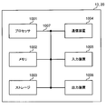
- FIG. 11 is a diagram illustrating an example of a hardware configuration of the radio base station and the user terminal according to the present embodiment.
- the above-described wireless base station 10 and user terminal 20 may be physically configured as a computer device including a processor 1001, a memory 1002, a storage 1003, a communication device 1004, an input device 1005, an output device 1006, a bus 1007, and the like. Good.
- the term “apparatus” can be read as a circuit, a device, a unit, or the like.
- the hardware configuration of the radio base station 10 and the user terminal 20 may be configured to include one or more of the devices illustrated in the drawing, or may be configured to exclude some of the devices.
- processor 1001 may be implemented by one or more chips.
- the functions of the radio base station 10 and the user terminal 20 are performed, for example, by reading predetermined software (program) on hardware such as the processor 1001 and the memory 1002, so that the processor 1001 performs an arithmetic operation and the communication device 1004. It is realized by controlling communication and controlling reading and / or writing of data in the memory 1002 and the storage 1003.
- the processor 1001 controls the entire computer by operating an operating system, for example.
- the processor 1001 may be configured by a central processing unit (CPU: Central Processing Unit) including an interface with a peripheral device, a control device, an arithmetic device, a register, and the like.
- CPU Central Processing Unit
- the above-described baseband signal processing unit 104 (204), call processing unit 105, and the like may be realized by the processor 1001.
- the processor 1001 reads a program (program code), a software module, data, and the like from the storage 1003 and / or the communication device 1004 to the memory 1002, and executes various processes according to these.
- a program program code
- a program that causes a computer to execute at least a part of the operation described in the above embodiment is used.
- the control unit 401 of the user terminal 20 may be implemented by a control program stored in the memory 1002 and operated by the processor 1001, and other functional blocks may be implemented similarly.
- the memory 1002 is a computer-readable recording medium, for example, at least one of ROM (Read Only Memory), EPROM (Erasable Programmable ROM), EEPROM (Electrically EPROM), RAM (Random Access Memory), and other appropriate storage media. It may be constituted by one.
- the memory 1002 may be called a register, a cache, a main memory (main storage device), or the like.
- the memory 1002 can store a program (program code), a software module, and the like that can be executed to implement the wireless communication method according to the present embodiment.
- the storage 1003 is a computer-readable recording medium such as a flexible disk, a floppy (registered trademark) disk, a magneto-optical disk (for example, a compact disk (CD-ROM (Compact Disc) ROM, etc.), a digital versatile disc, At least one of a Blu-ray (registered trademark) disk, a removable disk, a hard disk drive, a smart card, a flash memory device (eg, a card, a stick, a key drive), a magnetic stripe, a database, a server, and other suitable storage media. May be configured.
- the storage 1003 may be called an auxiliary storage device.
- the communication device 1004 is hardware (transmitting / receiving device) for performing communication between computers via a wired and / or wireless network, and is also referred to as, for example, a network device, a network controller, a network card, a communication module, or the like.
- the communication device 1004 includes, for example, a high-frequency switch, a duplexer, a filter, a frequency synthesizer, and the like in order to realize, for example, Frequency Division Duplex (FDD) and / or Time Division Duplex (TDD). It may be configured.
- the transmission / reception antenna 101 (201), the amplifier unit 102 (202), the transmission / reception unit 103 (203), the transmission path interface 106, and the like may be realized by the communication device 1004.
- the input device 1005 is an input device (for example, a keyboard, a mouse, a microphone, a switch, a button, a sensor, and the like) that receives an external input.
- the output device 1006 is an output device that performs output to the outside (for example, a display, a speaker, an LED (Light Emitting Diode) lamp, and the like). Note that the input device 1005 and the output device 1006 may have an integrated configuration (for example, a touch panel).
- the devices such as the processor 1001 and the memory 1002 are connected by a bus 1007 for communicating information.
- the bus 1007 may be configured using a single bus, or may be configured using a different bus for each device.
- the radio base station 10 and the user terminal 20 include a microprocessor, a digital signal processor (DSP), an ASIC (Application Specific Integrated Circuit), an PLD (Programmable Logic Device), an FPGA (Field Programmable Gate Array), and the like. It may be configured to include hardware, and some or all of the functional blocks may be realized using the hardware. For example, the processor 1001 may be implemented using at least one of these pieces of hardware.
- DSP digital signal processor
- ASIC Application Specific Integrated Circuit
- PLD Programmable Logic Device
- FPGA Field Programmable Gate Array
- channels and / or symbols may be signals.
- the signal may be a message.
- the reference signal may be abbreviated as RS (Reference Signal), and may be referred to as a pilot, a pilot signal, or the like according to an applied standard.
- a component carrier (CC: Component Carrier) may be called a cell, a frequency carrier, a carrier frequency, or the like.
- the radio frame may be configured by one or a plurality of periods (frames) in a time domain.
- the one or more respective periods (frames) forming the radio frame may be referred to as a subframe.
- a subframe may be configured by one or more slots in the time domain.
- the subframe may be a fixed time length (eg, 1 ms) that does not depend on numerology.
- the slot may be configured by one or a plurality of symbols (OFDM (Orthogonal Frequency Division Multiplexing) symbol, SC-FDMA (Single Carrier Frequency Division Multiple Access) symbol, etc.) in the time domain.
- OFDM Orthogonal Frequency Division Multiplexing
- SC-FDMA Single Carrier Frequency Division Multiple Access
- the slot may be a time unit based on numerology.
- the slot may include a plurality of mini slots. Each minislot may be constituted by one or more symbols in the time domain. Also, the mini-slot may be called a sub-slot.
- Radio frames, subframes, slots, minislots, and symbols all represent time units when transmitting signals.
- the radio frame, the subframe, the slot, the minislot, and the symbol may have different names corresponding to each.
- one subframe may be called a transmission time interval (TTI: Transmission @ Time @ Interval)
- TTI Transmission @ Time @ Interval
- a plurality of consecutive subframes may be called a TTI
- one slot or one minislot is called a TTI.
- the subframe and / or TTI may be a subframe (1 ms) in the existing LTE, may be a period shorter than 1 ms (for example, 1 to 13 symbols), or may be a period longer than 1 ms.
- the unit representing the TTI may be called a slot, a minislot, or the like instead of a subframe.
- the TTI refers to, for example, a minimum time unit of scheduling in wireless communication.
- the radio base station performs scheduling to allocate radio resources (frequency bandwidth, transmission power, and the like that can be used in each user terminal) to each user terminal in TTI units.
- radio resources frequency bandwidth, transmission power, and the like that can be used in each user terminal
- TTI is not limited to this.
- the TTI may be a transmission time unit of a channel-encoded data packet (transport block), a code block, and / or a codeword, or may be a processing unit such as scheduling and link adaptation. Note that when a TTI is given, a time interval (for example, the number of symbols) to which a transport block, a code block, and / or a codeword are actually mapped may be shorter than the TTI.
- one slot or one minislot is called a TTI
- one or more TTIs may be the minimum time unit for scheduling. Further, the number of slots (mini-slot number) constituting the minimum time unit of the scheduling may be controlled.
- a TTI having a time length of 1 ms may be called a normal TTI (TTI in LTE@Rel.8-12), a normal TTI, a long TTI, a normal subframe, a normal subframe, a long subframe, or the like.
- a TTI shorter than the normal TTI may be called a shortened TTI, a short TTI, a partial TTI (partial or fractional TTI), a shortened subframe, a short subframe, a minislot, or a subslot.
- a long TTI (for example, a normal TTI, a subframe, etc.) may be read as a TTI having a time length exceeding 1 ms, and a short TTI (for example, a shortened TTI, etc.) may be replaced with a TTI shorter than the long TTI and 1 ms.
- the TTI having the above-described TTI length may be replaced with the TTI.
- a resource block is a resource allocation unit in the time domain and the frequency domain, and may include one or a plurality of continuous subcarriers (subcarriers) in the frequency domain. Further, the RB may include one or a plurality of symbols in a time domain, and may have a length of one slot, one minislot, one subframe, or one TTI. One TTI and one subframe may each be configured by one or a plurality of resource blocks.
- one or more RBs include a physical resource block (PRB: Physical @ RB), a subcarrier group (SCG: Sub-Carrier @ Group), a resource element group (REG: Resource @ Element @ Group), a PRB pair, an RB pair, and the like. May be called.
- a resource block may be composed of one or more resource elements (RE: Resource @ Element).
- RE Resource @ Element
- one RE may be a radio resource area of one subcarrier and one symbol.
- the structures of the above-described radio frame, subframe, slot, minislot, symbol, and the like are merely examples.
- the number of subframes included in a radio frame, the number of slots per subframe or radio frame, the number of minislots included in a slot, the number of symbols and RBs included in a slot or minislot, included in an RB The configuration of the number of subcarriers, the number of symbols in the TTI, the symbol length, the cyclic prefix (CP: Cyclic @ Prefix) length, and the like can be variously changed.
- the information, parameters, and the like described in this specification may be expressed using an absolute value, may be expressed using a relative value from a predetermined value, or may use another corresponding information. May be expressed as For example, a radio resource may be indicated by a predetermined index.
- Names used for parameters and the like in this specification are not restrictive in any way.
- various channels PUCCH (Physical Uplink Control Channel), PDCCH (Physical Downlink Control Channel), etc.
- information elements can be identified by any suitable name, so that various channels assigned to these various channels and information elements can be identified.
- the nomenclature is not a limiting name in any respect.
- information, signals, and the like can be output from an upper layer to a lower layer and / or from a lower layer to an upper layer.
- Information, signals, etc. may be input / output via a plurality of network nodes.
- Information and signals input and output may be stored in a specific place (for example, a memory) or may be managed using a management table. Information and signals that are input and output can be overwritten, updated, or added. The output information, signal, and the like may be deleted. The input information, signal, and the like may be transmitted to another device.
- Notification of information is not limited to the aspect / embodiment described in this specification, and may be performed using another method.
- the information is notified by physical layer signaling (for example, downlink control information (DCI: Downlink Control Information), uplink control information (UCI: Uplink Control Information)), higher layer signaling (for example, RRC (Radio Resource Control) signaling, It may be implemented by broadcast information (master information block (MIB: Master Information Block), system information block (SIB: System Information Block), etc.), MAC (Medium Access Control) signaling), other signals, or a combination thereof.
- DCI Downlink Control Information
- UCI Uplink Control Information
- RRC Radio Resource Control
- MIB Master Information Block
- SIB System Information Block
- MAC Medium Access Control
- the physical layer signaling may be called L1 / L2 (Layer 1 / Layer 2) control information (L1 / L2 control signal), L1 control information (L1 control signal), or the like.
- the RRC signaling may be referred to as an RRC message, and may be, for example, an RRC connection setup (RRCConnectionSetup) message, an RRC connection reconfiguration (RRCConnectionReconfiguration) message, or the like.
- the MAC signaling may be notified using, for example, a MAC control element (MAC @ CE (Control @ Element)).
- the notification of the predetermined information is not limited to an explicit notification, and is implicit (for example, by not performing the notification of the predetermined information or by another information). May be performed).
- the determination may be made by a value represented by 1 bit (0 or 1), or may be made by a boolean value represented by true or false. , May be performed by comparing numerical values (for example, comparison with a predetermined value).
- software, instructions, information, and the like may be transmitted and received via a transmission medium.
- a transmission medium For example, if the software uses wired technology (coaxial cable, fiber optic cable, twisted pair, digital subscriber line (DSL), etc.) and / or wireless technology (infrared, microwave, etc.), the website, server, etc. , Or when transmitted from another remote source, these wired and / or wireless technologies are included within the definition of the transmission medium.
- system and “network” are used interchangeably.
- base station (BS: Base @ Station)”, “wireless base station”, “eNB”, “gNB”, “cell”, “sector”, “cell group”, “carrier”, and “component”
- carrier may be used interchangeably.
- a base station may also be called a fixed station (fixed @ station), NodeB, eNodeB (eNB), access point (access @ point), transmission point, reception point, femtocell, small cell, and the like.
- a base station can accommodate one or more (eg, three) cells (also called sectors). If the base station accommodates multiple cells, the entire coverage area of the base station can be partitioned into multiple smaller areas, each smaller area being a base station subsystem (eg, a small indoor base station (RRH: Communication services can also be provided by Remote Radio Head)).
- a base station subsystem eg, a small indoor base station (RRH: Communication services can also be provided by Remote Radio Head).
- RRH small indoor base station
- the term “cell” or “sector” refers to part or all of the coverage area of a base station and / or base station subsystem that provides communication services in this coverage.
- MS mobile station
- UE user equipment
- terminal terminal
- a mobile station can be a subscriber station, mobile unit, subscriber unit, wireless unit, remote unit, mobile device, wireless device, wireless communication device, remote device, mobile subscriber station, access terminal, mobile terminal, wireless terminal, by one of ordinary skill in the art. It may also be called a terminal, a remote terminal, a handset, a user agent, a mobile client, a client or some other suitable term.
- the wireless base station in this specification may be replaced with a user terminal.
- each aspect / embodiment of the present disclosure may be applied to a configuration in which communication between a wireless base station and a user terminal is replaced with communication between a plurality of user terminals (D2D: Device-to-Device).
- the configuration may be such that the user terminal 20 has the function of the wireless base station 10 described above.
- words such as “up” and “down” may be read as “side”.
- an uplink channel may be read as a side channel.
- a user terminal in the present specification may be replaced with a wireless base station.
- the configuration may be such that the radio base station 10 has the function of the user terminal 20 described above.
- the operation performed by the base station may be performed by an upper node (upper node) in some cases.
- various operations performed for communication with a terminal include a base station, one or more network nodes other than the base station (eg, Obviously, it can be performed by MME (Mobility Management Entity), S-GW (Serving-Gateway) or the like, but not limited thereto, or a combination thereof.
- MME Mobility Management Entity
- S-GW Serving-Gateway
- Each aspect / embodiment described in the present specification may be used alone, may be used in combination, or may be used by switching with execution.
- the processing procedure, sequence, flowchart, and the like of each aspect / embodiment described in this specification may be interchanged as long as there is no inconsistency.
- the methods described herein present elements of various steps in a sample order, and are not limited to the specific order presented.
- LTE Long Term Evolution
- LTE-A Long Term Evolution-Advanced
- LTE-B LTE-Beyond
- SUPER 3G IMT-Advanced
- 4G 4th generation
- 5G 5th generation mobile communication system
- FRA Fluture Radio Access
- New-RAT Radio Access Technology
- NR New Radio
- NX New radio access
- FX Fluture radio access
- GSM registered trademark
- CDMA2000 Code Division Multiple Access 2000
- UMB Universal Mobile Broadband
- IEEE 802.11 Wi-Fi (registered trademark)
- IEEE 802.16 WiMAX (registered trademark)
- IEEE 802.20 UWB (Ultra-WideBand), Bluetooth (registered trademark)
- any reference to elements using designations such as "first,” “second,” etc., as used herein, does not generally limit the quantity or order of those elements. These designations may be used herein as a convenient way to distinguish between two or more elements. Thus, reference to a first and second element does not mean that only two elements can be employed or that the first element must precede the second element in any way.
- determining may encompass a wide variety of actions. For example, “determining” means calculating, computing, processing, deriving, investigating, looking up (eg, a table, database, or other data). It may be regarded as “determining” such as searching in a structure), ascertaining, and the like. Also, “determining” includes receiving (eg, receiving information), transmitting (eg, transmitting information), input (input), output (output), and access ( accessing) (e.g., accessing data in a memory) or the like. Also, “judgment (decision)” is regarded as “judgment (decision)” of resolving, selecting, selecting, establishing, comparing, etc. Is also good. That is, “judgment (decision)” may be regarded as “judgment (decision)” of any operation.
- connection refers to any direct or indirect connection or indirect connection between two or more elements. Coupling is meant and may include the presence of one or more intermediate elements between two elements “connected” or “coupled” to each other.
- the coupling or connection between the elements may be physical, logical, or a combination thereof. For example, “connection” may be read as “access”.
- the radio frequency domain can be considered “connected” or “coupled” to each other, such as by using electromagnetic energy having wavelengths in the microwave and / or light (both visible and invisible) regions.
Landscapes
- Engineering & Computer Science (AREA)
- Signal Processing (AREA)
- Computer Networks & Wireless Communication (AREA)
- Mobile Radio Communication Systems (AREA)
Abstract
Description
NRでは、上り制御情報(UCI:Uplink Control Information)の送信に用いられる上り制御チャネル(例えば、PUCCH)用の構成(フォーマット、PUCCHフォーマット(PF)等ともいう)が検討されている。
・1又は2ビットのUCI(例えば、HARQ-ACK及びSRの少なくとも一つ)の送信に用いられ、1又は2シンボルで送信されるPUCCHフォーマット(PF0、ショートPUCCH等ともいう)、
・1又は2ビットのUCI(例えば、HARQ-ACK及びSRの少なくとも一つ)の送信に用いられ、4シンボル以上で送信されるPUCCHフォーマット(PF1、ロングPUCCH等ともいう)、
・2ビットより大きいUCIの送信に用いられ、1又は2シンボルで送信されるPUCCHフォーマット(PF2、ショートPUCCH等ともいう)、
・2ビットより大きいUCIの送信に用いられ、4シンボル以上で送信されるPUCCHフォーマット(PF3、ロングPUCCH等ともいう)、
・2ビットより大きいUCIの送信に用いられ、4シンボル以上で送信され、PUCCHリソースが直交カバーコード(OCC:Orthogonal Cover Code)を含むPUCCHフォーマット(PF4、ロングPUCCH等ともいう)。
また、NRでは、PUCCH用の一以上のリソース(PUCCHリソース)のセットが上位レイヤシグナリングによりに設定(configure)されてもよい。なお、上位レイヤシグナリングによる設定とは、基地局(BS(Base Station)、送受信ポイント(TRP:Transmission/Reception Point)、eNB(eNodeB)、gNB(NR NodeB)等ともいう)からユーザ端末(UE(User Equipment)、端末、MS(Mobile station)等ともいう)に対して設定(configuration)情報を通知することであってもよい。
・RRC(Radio Resource Control)シグナリング、
・MAC(Medium Access Control)シグナリング(例えば、MAC制御要素(MAC CE(Control Element))、MAC PDU(Protocol Data Unit))、
・ブロードキャストチャネル(例えば、PBCH:Physical Broadcast Channel)によって伝送される情報(例えば、マスタ情報ブロック(MIB:Master Information Block))、
・システム情報(例えば、システム情報ブロック(SIB:System Information Block)、最低限のシステム情報(RMSI:Remaining Minimum System Information)、他のシステム情報(OSI:Other System Information))。
・PRIフィールドを含むDCIを伝送する下り制御チャネル(例えば、PDCCH:Physical Downlink Control Channel)の受信用の制御リソースセット(CORESET:Control Resource Set)p内の制御チャネル要素(CCE:Control Channel Element)の数(NCCE,p)、
・当該下り制御チャネルの受信用のCCE(例えば、最初のCCE)のインデックス(nCCE,p、CCEインデックス)。

第1の態様では、PUCCHリソースの決定に用いられるCCEインデックスの導出について説明する。
ユーザ端末は、同一のHARQ-ACKタイミング(例えば、同一のスロット)を示す複数のDCIが異なる周波数帯域で検出される場合、当該周波数帯域のインデックスに基づいて、PUCCHリソースの決定に用いるCCEインデックスを決定してもよい。
第1のCCEインデックス導出では、ユーザ端末は、同一のHARQ-ACKタイミングを示す複数のDCIを複数のセルで検出する場合、降順の最初のセルインデックス(すなわち、最大のセルインデックス)のセルで検出されるDCIから導出されるCCEインデックスに基づいて、PUCCHリソースを決定してもよい。
第2のCCEインデックス導出では、ユーザ端末は、同一のHARQ-ACKタイミングを示す複数のDCIを複数のセルで検出する場合、昇順の最初のセルインデックス(すなわち、最小のセルインデックス)のセルで検出されるDCIから導出されるCCEインデックスに基づいて、PUCCHリソースを決定してもよい。
第1及び第2のCCEインデックス導出において、ユーザ端末は、各DCI内の所定フィールド(例えば、下り割り当てインデックス(DAI:Downlink Assignment Index)フィールド)の値に基づいて、DCIの検出ミスを認識してもよい。
ユーザ端末は、同一のHARQ-ACKタイミングを示す複数のDCIが異なるセルで検出される場合、セルインデックスに加えて、DCI(PDCCH)のモニタリング機会(モニタリング用の期間、モニタリング期間等ともいう)に基づいて、PUCCHリソースの決定に用いるCCEインデックスを決定してもよい。
ユーザ端末は、同一のHARQ-ACKタイミング(例えば、同一のスロット)を示す複数のDCIが異なる時間帯域(例えば、複数のスロット、シンボル等)で検出される場合、当該複数のDCIが検出されるタイミングに基づいて、PUCCHリソースの決定に用いるCCEインデックスを決定してもよい。
・PUCCH送信用に同一のスロットを示すHARQ-ACKタイミングフィールド値を有するDCIの中で所定のDCIのPDCCH受信のCORESETp内のCCE数(NCCE,p)、
・PUCCH送信用に同一のスロットを示すHARQ-ACKタイミングフィールド値を有するDCIの中で最後のDCIのPDCCH受信の最初のCCEのCCEインデックス(nCCE,p)、
・PUCCH送信用に同一のスロットを示すHARQ-ACKタイミングフィールド値を有するDCIの中で最後のDCI内のPRI(ΔPRI)。
以上のように、第1の態様では、時間領域で複数のDCIが検出される場合と、周波数領域で複数のDCIが検出される場合とについて別々に説明したがこれに限られない。時間領域及び周波数領域で複数のDCIが検出される場合にも、上記内容を組み合わせて適用可能である。
第2の態様では、PUCCHリソースの決定に用いられるCCE数の導出について説明する。ユーザ端末は、上記式(1)に例示されるように、所定のDCIが配置されるCORESET内のCCE数に基づいて、PUCCHリソースを決定することが想定される。
第2の態様において、ユーザ端末は、CCEインデックス(nCCE,p)の導出に用いられるDCIが配置されるCORESET内のCCE数に基づいて、PUCCHリソースを決定してもよい。
或いは、第2の態様において、ユーザ端末は、PRIの導出に用いられるDCIが配置されるCORESET内のCCE数に基づいて、PUCCHリソースを決定してもよい。
或いは、第2の態様において、ユーザ端末は、CCEインデックス及びPRIの少なくとも一つとは独立したルールに基づいてCCE数を導出し、導出されたCCE数に基づいてPUCCHリソースを決定してもよい。
以下、本実施の形態に係る無線通信システムの構成について説明する。この無線通信システムでは、本開示の上記各態様の少なくとも一つの組み合わせを用いて通信が行われる。
図7は、本実施の形態に係る無線基地局の全体構成の一例を示す図である。無線基地局10は、複数の送受信アンテナ101と、アンプ部102と、送受信部103と、ベースバンド信号処理部104と、呼処理部105と、伝送路インターフェース106と、を備えている。なお、送受信アンテナ101、アンプ部102、送受信部103は、それぞれ1つ以上を含むように構成されればよい。
図9は、本実施の形態に係るユーザ端末の全体構成の一例を示す図である。ユーザ端末20は、複数の送受信アンテナ201と、アンプ部202と、送受信部203と、ベースバンド信号処理部204と、アプリケーション部205と、を備えている。なお、送受信アンテナ201、アンプ部202、送受信部203は、それぞれ1つ以上を含むように構成されればよい。
なお、上記実施の形態の説明に用いたブロック図は、機能単位のブロックを示している。これらの機能ブロック(構成部)は、ハードウェア及び/又はソフトウェアの任意の組み合わせによって実現される。また、各機能ブロックの実現方法は特に限定されない。すなわち、各機能ブロックは、物理的及び/又は論理的に結合した1つの装置を用いて実現されてもよいし、物理的及び/又は論理的に分離した2つ以上の装置を直接的及び/又は間接的に(例えば、有線及び/又は無線を用いて)接続し、これら複数の装置を用いて実現されてもよい。
なお、本明細書において説明した用語及び/又は本明細書の理解に必要な用語については、同一の又は類似する意味を有する用語と置き換えてもよい。例えば、チャネル及び/又はシンボルは信号(シグナリング)であってもよい。また、信号はメッセージであってもよい。参照信号は、RS(Reference Signal)と略称することもでき、適用される標準によってパイロット(Pilot)、パイロット信号などと呼ばれてもよい。また、コンポーネントキャリア(CC:Component Carrier)は、セル、周波数キャリア、キャリア周波数などと呼ばれてもよい。
Claims (6)
- 複数の下り共有チャネルに対する送達確認情報の送信に用いられる上り制御チャネル用に同一のスロットを示す所定フィールド値をそれぞれ含む複数の下り制御情報(DCI)を受信する受信部と、
前記上り制御チャネル用のリソースの決定に用いられる制御チャネル要素(CCE)のインデックスの導出を制御する制御部と、
を具備することを特徴とするユーザ端末。 - 前記制御部は、前記複数のDCIが複数のセルで検出される場合、前記複数のセルの中で降順又は昇順の最初のインデックスのセルで検出されるDCIを用いて導出される制御チャネル要素(CCE)のインデックスに基づいて、前記リソースを決定することを特徴とする請求項1に記載のユーザ端末。
- 前記制御部は、前記複数のDCIが異なる時間領域リソースで検出される場合、最後のDCIを用いて導出される制御チャネル要素(CCE)のインデックスに基づいて、前記リソースを決定することを特徴とする請求項1又は請求項2に記載のユーザ端末。
- 前記制御部は、前記CCEのインデックスの導出に用いられるDCIの検出ミスを認識する場合、
前記CCEのインデックスが固定値であると想定して前記リソースを決定する、
前記リソースの識別子に基づいて前記リソースを決定する、又は、
実際に検出されたDCIの中で所定のルールに基づいて決定されるDCIが配置されるCCEのインデックスに基づいて前記リソースを決定することを特徴とする請求項2又は請求項3に記載のユーザ端末。 - 前記制御部は、前記CCEのインデックスの導出に用いられるDCIが配置される制御リソースセット内のCCEの数に基づいて、前記リソースを決定することを特徴とする請求項1から請求項4のいずれかに記載のユーザ端末。
- 前記制御部は、前記CCEのインデックスとは独立したルールを用いて導出されるDCIが配置される制御リソースセット内のCCEの数に基づいて、前記リソースを決定することを特徴とする請求項1から請求項4のいずれかに記載のユーザ端末。
Priority Applications (6)
| Application Number | Priority Date | Filing Date | Title |
|---|---|---|---|
| PCT/JP2018/028325 WO2020021720A1 (ja) | 2018-07-27 | 2018-07-27 | ユーザ端末 |
| US17/260,387 US12035340B2 (en) | 2018-07-27 | 2018-07-27 | User terminal |
| EP18927916.9A EP3833124A4 (en) | 2018-07-27 | 2018-07-27 | USER TERMINAL |
| CN201880098083.9A CN112753260B (zh) | 2018-07-27 | 2018-07-27 | 用户终端 |
| BR112021001358-0A BR112021001358A2 (pt) | 2018-07-27 | 2018-07-27 | terminal de usuário |
| JP2020532125A JP7140833B2 (ja) | 2018-07-27 | 2018-07-27 | 端末、無線通信方法、基地局及びシステム |
Applications Claiming Priority (1)
| Application Number | Priority Date | Filing Date | Title |
|---|---|---|---|
| PCT/JP2018/028325 WO2020021720A1 (ja) | 2018-07-27 | 2018-07-27 | ユーザ端末 |
Publications (1)
| Publication Number | Publication Date |
|---|---|
| WO2020021720A1 true WO2020021720A1 (ja) | 2020-01-30 |
Family
ID=69182271
Family Applications (1)
| Application Number | Title | Priority Date | Filing Date |
|---|---|---|---|
| PCT/JP2018/028325 Ceased WO2020021720A1 (ja) | 2018-07-27 | 2018-07-27 | ユーザ端末 |
Country Status (6)
| Country | Link |
|---|---|
| US (1) | US12035340B2 (ja) |
| EP (1) | EP3833124A4 (ja) |
| JP (1) | JP7140833B2 (ja) |
| CN (1) | CN112753260B (ja) |
| BR (1) | BR112021001358A2 (ja) |
| WO (1) | WO2020021720A1 (ja) |
Cited By (5)
| Publication number | Priority date | Publication date | Assignee | Title |
|---|---|---|---|---|
| CN112425241A (zh) * | 2020-10-12 | 2021-02-26 | 北京小米移动软件有限公司 | 信息的接收、发送方法、装置、设备及可读存储介质 |
| JPWO2021157197A1 (ja) * | 2020-02-05 | 2021-08-12 | ||
| JP2022154664A (ja) * | 2021-03-30 | 2022-10-13 | Kddi株式会社 | 拡張された確認応答を用いる端末装置、基地局装置、通信方法、およびプログラム |
| JP2023546875A (ja) * | 2020-10-16 | 2023-11-08 | 日本電気株式会社 | 端末装置、ネットワーク装置、及び端末装置により実行される方法 |
| JP2024527123A (ja) * | 2021-07-30 | 2024-07-19 | 維沃移動通信有限公司 | 上りリンク伝送方法、装置及び端末 |
Families Citing this family (4)
| Publication number | Priority date | Publication date | Assignee | Title |
|---|---|---|---|---|
| CN108282881B (zh) * | 2017-01-06 | 2020-12-15 | 华为技术有限公司 | 一种资源配置方法及装置 |
| US20220182188A1 (en) * | 2020-12-09 | 2022-06-09 | Samsung Electronics Co., Ltd. | Method and device to transmit and receive hybrid automatic retransmission request acknowledgement information |
| WO2022175876A1 (en) * | 2021-02-17 | 2022-08-25 | Lenovo (Singapore) Pte. Ltd. | Enhanced multiplexing of uplink control information of different priorities |
| WO2024007260A1 (zh) * | 2022-07-07 | 2024-01-11 | Oppo广东移动通信有限公司 | 通信方法、终端设备以及网络设备 |
Family Cites Families (17)
| Publication number | Priority date | Publication date | Assignee | Title |
|---|---|---|---|---|
| WO2008156034A1 (ja) * | 2007-06-18 | 2008-12-24 | Sharp Kabushiki Kaisha | 移動局、移動通信システム及び通信方法 |
| WO2011049354A2 (en) * | 2009-10-19 | 2011-04-28 | Samsung Electronics Co., Ltd. | Transmission diversity and multiplexing for harq-ack signals in communication systems |
| US20130039290A1 (en) * | 2011-08-11 | 2013-02-14 | Research In Motion Korea | Method and System for Uplink Control Channel Transmit Diversity Using Multiple Downlink Control Channel Based Resource Allocation |
| JP5927661B2 (ja) * | 2011-08-12 | 2016-06-01 | シャープ株式会社 | 端末装置、基地局装置、集積回路および通信方法 |
| JP5719085B2 (ja) * | 2011-10-24 | 2015-05-13 | エルジー エレクトロニクス インコーポレイティド | 無線通信システムにおいてリソースを割り当てる方法及びそのための装置 |
| JP5490773B2 (ja) * | 2011-11-28 | 2014-05-14 | シャープ株式会社 | 基地局装置および通信方法 |
| US9001798B2 (en) * | 2012-03-05 | 2015-04-07 | Samsung Electronics Co., Ltd. | HARQ-ACK signal transmission in response to detection of control channel type in case of multiple control channel types |
| JP6179009B2 (ja) * | 2012-09-20 | 2017-08-16 | シャープ株式会社 | 端末装置、基地局装置、無線通信方法、および集積回路 |
| KR20140148281A (ko) * | 2013-06-21 | 2014-12-31 | 주식회사 케이티 | 상향링크 제어 채널에서의 응답 신호를 위한 리소스 할당을 제어하는 방법 및 그 장치 |
| CN104348591B (zh) * | 2013-08-01 | 2019-03-12 | 中兴通讯股份有限公司 | 一种上行控制信息的发送方法及用户设备、基站 |
| CN107079440A (zh) * | 2014-11-06 | 2017-08-18 | 株式会社Ntt都科摩 | 用户终端、无线基站以及无线通信方法 |
| JP6081531B2 (ja) * | 2015-06-26 | 2017-02-15 | 株式会社Nttドコモ | ユーザ端末、無線基地局及び無線通信方法 |
| US10541785B2 (en) * | 2016-07-18 | 2020-01-21 | Samsung Electronics Co., Ltd. | Carrier aggregation with variable transmission durations |
| JP7103945B2 (ja) * | 2016-09-29 | 2022-07-20 | 株式会社Nttドコモ | 端末及び無線通信方法 |
| PT3547773T (pt) * | 2016-11-25 | 2022-06-01 | Ntt Docomo Inc | Terminal de utilizador e método de comunicação sem fios |
| US10492184B2 (en) * | 2016-12-09 | 2019-11-26 | Samsung Electronics Co., Ltd. | Multiplexing control information in a physical uplink data channel |
| WO2018127628A1 (en) * | 2017-01-05 | 2018-07-12 | Nokia Technologies Oy | Scalable feedback reporting |
-
2018
- 2018-07-27 CN CN201880098083.9A patent/CN112753260B/zh active Active
- 2018-07-27 JP JP2020532125A patent/JP7140833B2/ja active Active
- 2018-07-27 WO PCT/JP2018/028325 patent/WO2020021720A1/ja not_active Ceased
- 2018-07-27 BR BR112021001358-0A patent/BR112021001358A2/pt unknown
- 2018-07-27 US US17/260,387 patent/US12035340B2/en active Active
- 2018-07-27 EP EP18927916.9A patent/EP3833124A4/en active Pending
Non-Patent Citations (6)
| Title |
|---|
| "Evolved Universal Terrestrial Radio Access (E-UTRA) and Evolved Universal Terrestrial Radio Access Network (E-UTRAN); Overall description; Stage 2 (Release 8", 3GPP TS 36.300, April 2010 (2010-04-01) |
| NTT DOCOMO, INC.: "On HARQ-ACK feedback", 3GPP TSG-RAN WG1#93 R1-1807067, 12 May 2018 (2018-05-12), XP051442265 * |
| OPPO: "Remaining issues on resource allocation for PUCCH", 3GPP TSG-RAN WG1#92BIS R1-1804015, 6 April 2018 (2018-04-06), XP051413104 * |
| OPPO: "Summary of offline discussion on PUCCH resource allocation", 3GPP TSG-RAN WG1#92BIS R1-1805742, 24 April 2018 (2018-04-24), XP051435694 * |
| PANASONIC: "Discussion on remaining issues on PUCCH resource allocation", 3GPP TSG-RAN WG1#92BIS R1-1804483, 6 April 2018 (2018-04-06), XP051413303 * |
| See also references of EP3833124A4 |
Cited By (15)
| Publication number | Priority date | Publication date | Assignee | Title |
|---|---|---|---|---|
| EP4102910A4 (en) * | 2020-02-05 | 2023-05-10 | Panasonic Intellectual Property Corporation of America | TERMINAL AND COMMUNICATION METHOD |
| JPWO2021157197A1 (ja) * | 2020-02-05 | 2021-08-12 | ||
| WO2021157197A1 (ja) * | 2020-02-05 | 2021-08-12 | パナソニック インテレクチュアル プロパティ コーポレーション オブ アメリカ | 端末及び通信方法 |
| TWI893053B (zh) * | 2020-02-05 | 2025-08-11 | 美商松下電器(美國)知識產權公司 | 終端與通訊方法 |
| CN115039477A (zh) * | 2020-02-05 | 2022-09-09 | 松下电器(美国)知识产权公司 | 终端及通信方法 |
| US12356408B2 (en) | 2020-02-05 | 2025-07-08 | Panasonic Intellectual Property Corporation Of America | Terminal and communication method |
| WO2022077164A1 (zh) * | 2020-10-12 | 2022-04-21 | 北京小米移动软件有限公司 | 信息的接收、发送方法、装置、设备及可读存储介质 |
| CN112425241B (zh) * | 2020-10-12 | 2023-10-10 | 北京小米移动软件有限公司 | 信息的接收、发送方法、装置、设备及可读存储介质 |
| CN112425241A (zh) * | 2020-10-12 | 2021-02-26 | 北京小米移动软件有限公司 | 信息的接收、发送方法、装置、设备及可读存储介质 |
| US12532328B2 (en) | 2020-10-12 | 2026-01-20 | Beijing Xiaomi Mobile Software Co., Ltd. | Information receiving and sending method, device and readable storage medium |
| JP2023546875A (ja) * | 2020-10-16 | 2023-11-08 | 日本電気株式会社 | 端末装置、ネットワーク装置、及び端末装置により実行される方法 |
| JP7743864B2 (ja) | 2020-10-16 | 2025-09-25 | 日本電気株式会社 | 端末装置、ネットワーク装置、及び端末装置により実行される方法 |
| JP7408596B2 (ja) | 2021-03-30 | 2024-01-05 | Kddi株式会社 | 拡張された確認応答を用いる端末装置、基地局装置、通信方法、およびプログラム |
| JP2022154664A (ja) * | 2021-03-30 | 2022-10-13 | Kddi株式会社 | 拡張された確認応答を用いる端末装置、基地局装置、通信方法、およびプログラム |
| JP2024527123A (ja) * | 2021-07-30 | 2024-07-19 | 維沃移動通信有限公司 | 上りリンク伝送方法、装置及び端末 |
Also Published As
| Publication number | Publication date |
|---|---|
| EP3833124A1 (en) | 2021-06-09 |
| JPWO2020021720A1 (ja) | 2021-08-02 |
| CN112753260A (zh) | 2021-05-04 |
| BR112021001358A2 (pt) | 2021-04-20 |
| CN112753260B (zh) | 2024-03-01 |
| JP7140833B2 (ja) | 2022-09-21 |
| EP3833124A4 (en) | 2022-03-30 |
| US12035340B2 (en) | 2024-07-09 |
| US20210298028A1 (en) | 2021-09-23 |
Similar Documents
| Publication | Publication Date | Title |
|---|---|---|
| JP7092799B2 (ja) | 端末、無線通信方法、基地局及びシステム | |
| JP6980786B2 (ja) | 端末、無線通信方法及び基地局 | |
| US11700607B2 (en) | User terminal, radio base station and radio communication method | |
| JP7183260B2 (ja) | 端末、無線通信方法、基地局及びシステム | |
| JP7140833B2 (ja) | 端末、無線通信方法、基地局及びシステム | |
| JP7007399B2 (ja) | 端末、無線通信方法、基地局及びシステム | |
| WO2019193688A1 (ja) | ユーザ端末及び無線通信方法 | |
| CN111869175B (zh) | 用户终端以及无线通信方法 | |
| JPWO2018158923A1 (ja) | ユーザ端末及び無線通信方法 | |
| JP7252224B2 (ja) | 端末、無線通信方法、基地局及びシステム | |
| WO2019107239A1 (ja) | ユーザ端末及び無線通信方法 | |
| WO2019168051A1 (ja) | ユーザ端末及び無線通信方法 | |
| WO2020039483A1 (ja) | ユーザ端末 | |
| WO2019198136A1 (ja) | ユーザ端末及び無線基地局 | |
| JP7252223B2 (ja) | 端末、無線通信方法、基地局及びシステム | |
| JPWO2018207374A1 (ja) | ユーザ端末及び無線通信方法 | |
| WO2020017059A1 (ja) | ユーザ端末 | |
| WO2019215935A1 (ja) | ユーザ端末及び無線通信方法 | |
| JPWO2019175989A1 (ja) | ユーザ端末及び無線通信方法 | |
| US11683129B2 (en) | User terminal and radio communication method | |
| JPWO2019167939A1 (ja) | ユーザ端末及び無線通信方法 | |
| WO2020017058A1 (ja) | 基地局及びユーザ端末 | |
| WO2019215898A1 (ja) | ユーザ端末及び無線通信方法 | |
| WO2019225655A1 (ja) | ユーザ端末 | |
| WO2020017057A1 (ja) | ユーザ端末 |
Legal Events
| Date | Code | Title | Description |
|---|---|---|---|
| 121 | Ep: the epo has been informed by wipo that ep was designated in this application |
Ref document number: 18927916 Country of ref document: EP Kind code of ref document: A1 |
|
| ENP | Entry into the national phase |
Ref document number: 2020532125 Country of ref document: JP Kind code of ref document: A |
|
| NENP | Non-entry into the national phase |
Ref country code: DE |
|
| REG | Reference to national code |
Ref country code: BR Ref legal event code: B01A Ref document number: 112021001358 Country of ref document: BR |
|
| ENP | Entry into the national phase |
Ref document number: 2018927916 Country of ref document: EP Effective date: 20210301 |
|
| ENP | Entry into the national phase |
Ref document number: 112021001358 Country of ref document: BR Kind code of ref document: A2 Effective date: 20210125 |