WO2020021785A1 - Dispositif de détection de gaz, procédé de détection de gaz, procédé de commande d'affichage et programme - Google Patents
Dispositif de détection de gaz, procédé de détection de gaz, procédé de commande d'affichage et programme Download PDFInfo
- Publication number
- WO2020021785A1 WO2020021785A1 PCT/JP2019/015889 JP2019015889W WO2020021785A1 WO 2020021785 A1 WO2020021785 A1 WO 2020021785A1 JP 2019015889 W JP2019015889 W JP 2019015889W WO 2020021785 A1 WO2020021785 A1 WO 2020021785A1
- Authority
- WO
- WIPO (PCT)
- Prior art keywords
- unit
- image
- input
- display
- information
- Prior art date
- Legal status (The legal status is an assumption and is not a legal conclusion. Google has not performed a legal analysis and makes no representation as to the accuracy of the status listed.)
- Ceased
Links
Images







Classifications
-
- H—ELECTRICITY
- H04—ELECTRIC COMMUNICATION TECHNIQUE
- H04N—PICTORIAL COMMUNICATION, e.g. TELEVISION
- H04N5/00—Details of television systems
- H04N5/76—Television signal recording
- H04N5/765—Interface circuits between an apparatus for recording and another apparatus
- H04N5/77—Interface circuits between an apparatus for recording and another apparatus between a recording apparatus and a television camera
-
- G—PHYSICS
- G06—COMPUTING OR CALCULATING; COUNTING
- G06T—IMAGE DATA PROCESSING OR GENERATION, IN GENERAL
- G06T7/00—Image analysis
- G06T7/0002—Inspection of images, e.g. flaw detection
-
- G—PHYSICS
- G01—MEASURING; TESTING
- G01M—TESTING STATIC OR DYNAMIC BALANCE OF MACHINES OR STRUCTURES; TESTING OF STRUCTURES OR APPARATUS, NOT OTHERWISE PROVIDED FOR
- G01M3/00—Investigating fluid-tightness of structures
- G01M3/02—Investigating fluid-tightness of structures by using fluid or vacuum
-
- G—PHYSICS
- G01—MEASURING; TESTING
- G01M—TESTING STATIC OR DYNAMIC BALANCE OF MACHINES OR STRUCTURES; TESTING OF STRUCTURES OR APPARATUS, NOT OTHERWISE PROVIDED FOR
- G01M3/00—Investigating fluid-tightness of structures
- G01M3/38—Investigating fluid-tightness of structures by using light
-
- G—PHYSICS
- G06—COMPUTING OR CALCULATING; COUNTING
- G06F—ELECTRIC DIGITAL DATA PROCESSING
- G06F3/00—Input arrangements for transferring data to be processed into a form capable of being handled by the computer; Output arrangements for transferring data from processing unit to output unit, e.g. interface arrangements
- G06F3/01—Input arrangements or combined input and output arrangements for interaction between user and computer
- G06F3/048—Interaction techniques based on graphical user interfaces [GUI]
- G06F3/0481—Interaction techniques based on graphical user interfaces [GUI] based on specific properties of the displayed interaction object or a metaphor-based environment, e.g. interaction with desktop elements like windows or icons, or assisted by a cursor's changing behaviour or appearance
- G06F3/0482—Interaction with lists of selectable items, e.g. menus
-
- G—PHYSICS
- G06—COMPUTING OR CALCULATING; COUNTING
- G06F—ELECTRIC DIGITAL DATA PROCESSING
- G06F3/00—Input arrangements for transferring data to be processed into a form capable of being handled by the computer; Output arrangements for transferring data from processing unit to output unit, e.g. interface arrangements
- G06F3/01—Input arrangements or combined input and output arrangements for interaction between user and computer
- G06F3/048—Interaction techniques based on graphical user interfaces [GUI]
- G06F3/0484—Interaction techniques based on graphical user interfaces [GUI] for the control of specific functions or operations, e.g. selecting or manipulating an object, an image or a displayed text element, setting a parameter value or selecting a range
- G06F3/04847—Interaction techniques to control parameter settings, e.g. interaction with sliders or dials
-
- G—PHYSICS
- G06—COMPUTING OR CALCULATING; COUNTING
- G06T—IMAGE DATA PROCESSING OR GENERATION, IN GENERAL
- G06T11/00—Two-dimensional [2D] image generation
-
- G—PHYSICS
- G06—COMPUTING OR CALCULATING; COUNTING
- G06T—IMAGE DATA PROCESSING OR GENERATION, IN GENERAL
- G06T11/00—Two-dimensional [2D] image generation
- G06T11/10—Texturing; Colouring; Generation of textures or colours
-
- G—PHYSICS
- G06—COMPUTING OR CALCULATING; COUNTING
- G06T—IMAGE DATA PROCESSING OR GENERATION, IN GENERAL
- G06T11/00—Two-dimensional [2D] image generation
- G06T11/20—Drawing from basic elements
- G06T11/26—Drawing of charts or graphs
-
- G—PHYSICS
- G06—COMPUTING OR CALCULATING; COUNTING
- G06T—IMAGE DATA PROCESSING OR GENERATION, IN GENERAL
- G06T7/00—Image analysis
- G06T7/0002—Inspection of images, e.g. flaw detection
- G06T7/0004—Industrial image inspection
-
- G—PHYSICS
- G11—INFORMATION STORAGE
- G11B—INFORMATION STORAGE BASED ON RELATIVE MOVEMENT BETWEEN RECORD CARRIER AND TRANSDUCER
- G11B27/00—Editing; Indexing; Addressing; Timing or synchronising; Monitoring; Measuring tape travel
- G11B27/10—Indexing; Addressing; Timing or synchronising; Measuring tape travel
- G11B27/11—Indexing; Addressing; Timing or synchronising; Measuring tape travel by using information not detectable on the record carrier
-
- G—PHYSICS
- G11—INFORMATION STORAGE
- G11B—INFORMATION STORAGE BASED ON RELATIVE MOVEMENT BETWEEN RECORD CARRIER AND TRANSDUCER
- G11B27/00—Editing; Indexing; Addressing; Timing or synchronising; Monitoring; Measuring tape travel
- G11B27/10—Indexing; Addressing; Timing or synchronising; Measuring tape travel
- G11B27/19—Indexing; Addressing; Timing or synchronising; Measuring tape travel by using information detectable on the record carrier
- G11B27/28—Indexing; Addressing; Timing or synchronising; Measuring tape travel by using information detectable on the record carrier by using information signals recorded by the same method as the main recording
-
- H—ELECTRICITY
- H04—ELECTRIC COMMUNICATION TECHNIQUE
- H04N—PICTORIAL COMMUNICATION, e.g. TELEVISION
- H04N5/00—Details of television systems
- H04N5/76—Television signal recording
- H04N5/91—Television signal processing therefor
- H04N5/92—Transformation of the television signal for recording, e.g. modulation, frequency changing; Inverse transformation for playback
- H04N5/9201—Transformation of the television signal for recording, e.g. modulation, frequency changing; Inverse transformation for playback involving the multiplexing of an additional signal and the video signal
- H04N5/9206—Transformation of the television signal for recording, e.g. modulation, frequency changing; Inverse transformation for playback involving the multiplexing of an additional signal and the video signal the additional signal being a character code signal
-
- H—ELECTRICITY
- H04—ELECTRIC COMMUNICATION TECHNIQUE
- H04N—PICTORIAL COMMUNICATION, e.g. TELEVISION
- H04N9/00—Details of colour television systems
- H04N9/79—Processing of colour television signals in connection with recording
- H04N9/80—Transformation of the television signal for recording, e.g. modulation, frequency changing; Inverse transformation for playback
- H04N9/82—Transformation of the television signal for recording, e.g. modulation, frequency changing; Inverse transformation for playback the individual colour picture signal components being recorded simultaneously only
- H04N9/8205—Transformation of the television signal for recording, e.g. modulation, frequency changing; Inverse transformation for playback the individual colour picture signal components being recorded simultaneously only involving the multiplexing of an additional signal and the colour video signal
-
- G—PHYSICS
- G06—COMPUTING OR CALCULATING; COUNTING
- G06T—IMAGE DATA PROCESSING OR GENERATION, IN GENERAL
- G06T2200/00—Indexing scheme for image data processing or generation, in general
- G06T2200/24—Indexing scheme for image data processing or generation, in general involving graphical user interfaces [GUIs]
-
- G—PHYSICS
- G06—COMPUTING OR CALCULATING; COUNTING
- G06T—IMAGE DATA PROCESSING OR GENERATION, IN GENERAL
- G06T2207/00—Indexing scheme for image analysis or image enhancement
- G06T2207/10—Image acquisition modality
- G06T2207/10024—Color image
-
- G—PHYSICS
- G06—COMPUTING OR CALCULATING; COUNTING
- G06T—IMAGE DATA PROCESSING OR GENERATION, IN GENERAL
- G06T2207/00—Indexing scheme for image analysis or image enhancement
- G06T2207/10—Image acquisition modality
- G06T2207/10048—Infrared image
Definitions
- the present invention relates to a gas detection device, a gas detection method, a display control method, and a program.
- Patent Document 1 Japanese Patent Document 1
- Patent Literature 1 discloses an infrared camera and a visible light camera for capturing an image (moving image) of an inspection area including an inspection target, an image processing unit for processing infrared image data captured by the infrared camera, and a display. And a gas leak detection device having the same.
- the image processing unit extracts an image of fluctuation caused by gas leakage from the image data of the inspection area.
- the display unit displays an inspection image in which the fluctuation image data is superimposed on the image data of the inspection area captured by the visible light camera.
- the inspector visually and easily identifies the location of the gas leak in the inspection area by visually checking the inspection image displayed on the display unit. it can.
- the importance of the image differs between the normal image of the inspection target and the emergency image in which gas leakage occurs in the inspection target.
- inspection images may require images of a predetermined time including a normal image and an emergency image, for example, a specific image (for example, only an emergency image) is required. In some cases. If the user can add supplementary information to a specific image in the inspection image, the specific image can be efficiently extracted from the inspection image.
- the gas detection device disclosed in Patent Document 1 does not have such a configuration.
- An object of the present invention is to provide a gas detection device, a gas detection method, a display control method, and a program that can add supplementary information to a specific image in an inspection image.
- One aspect of the gas detection device is an image processing unit that performs image processing on infrared image data of an inspection area imaged by an imaging unit to visualize gas, and an inspection image that reflects the result of the image processing.
- the display device includes a display processing unit to be displayed on the display unit, and an input unit to receive input of supplementary information on the inspection image displayed on the display unit.
- One aspect of the gas detection device is an image processing unit that performs image processing on infrared image data of an inspection region imaged by an imaging unit to visualize the gas, and detects the gas based on a result of the image processing.
- One aspect of the gas detection method according to the present invention is a gas detection method executed in a gas detection device, in which the gas is visualized by performing image processing on infrared image data of an inspection region captured by an imaging unit, The inspection image reflecting the result of the image processing is displayed on the display unit, and input of supplementary information on the inspection image displayed on the display unit is received.
- One aspect of the program according to the present invention is to provide a computer of a gas detection device that displays an inspection image in which a gas is visualized on a display unit, by performing image processing on infrared image data of an inspection region imaged by an imaging unit and extracting the gas.
- a process of visualizing, a process of displaying an inspection image reflecting the result of the image processing on the display unit, and a process of receiving input of supplementary information on the inspection image displayed on the display unit are executed.
- a gas detection device it is possible to provide a gas detection device, a gas detection method, a display control method, and a program that can add supplementary information to a specific image in an inspection image.
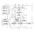
- FIG. 1 is a block diagram illustrating a configuration example of a gas detection device according to an embodiment of the present invention.
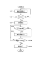
- FIG. 2 is a flowchart for explaining a flow when supplementary information is input during imaging.
- FIG. 3 is a flowchart for explaining a flow when inputting supplementary information during reproduction.
- FIG. 4 is a flowchart for explaining a flow when generating and outputting output information.
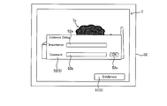
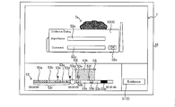
- FIG. 5A is a diagram illustrating an example of an inspection image displayed on a display unit during imaging.
- FIG. 5B is a diagram illustrating an example of the inspection image of the display unit changed from the state illustrated in FIG. 5A.
- FIG. 6A is a diagram illustrating a first modification of the second input screen.
- FIG. 5A is a diagram illustrating an example of an inspection image displayed on a display unit during imaging.
- FIG. 5B is a diagram illustrating an example of the inspection image of the display unit changed from the state illustrated in FIG. 5A.
- FIG. 6A is
- FIG. 6B is a diagram illustrating a first modification of the second input screen in a state different from that of FIG. 6A.
- FIG. 7A is a diagram illustrating an example of an inspection image displayed on the display unit during reproduction.
- FIG. 7B is a diagram illustrating an example of the inspection image of the display unit changed from the state illustrated in FIG. 7A.
- FIG. 8 is a block diagram illustrating a configuration example of a gas detection device according to another embodiment of the present invention.
- FIG. 9A is a diagram illustrating an example of an inspection image displayed on a display unit during imaging.
- FIG. 9B is a diagram illustrating an example of the inspection image of the display unit changed from the state illustrated in FIG. 9A.
- FIG. 10A is a diagram illustrating a modification of the second input image.
- FIG. 10A is a diagram illustrating a modification of the second input image.
- FIG. 10B is a diagram illustrating a modified example of the second input image in a state different from FIG. 10A.
- FIG. 11A is a diagram illustrating an example of an inspection image displayed on the display unit during reproduction.
- FIG. 11B is a diagram illustrating an example of the inspection image of the display unit changed from the state illustrated in FIG. 11A.
- FIG. 12 is a flowchart illustrating an example of the operation of the gas detection device.
- FIG. 1 is a block diagram of the gas detection device 1.
- the gas detection device 1 captures, for example, an inspection area including an inspection target (a plant or the like) in a gas field, and generates infrared image data of the inspection area. Then, the gas detection device 1 performs image processing on the infrared image data to generate an inspection image in which the gas is visualized. Further, in the case of the gas detection device 1 according to the present embodiment, the user can add supplementary information to the inspection image at an arbitrary timing while visually recognizing the inspection image displayed on the display unit. In the following description, images include not only still images but also moving images.
- the gas detection device 1 includes an imaging device 2 and a gas detection device main body 3.
- the imaging device 2 and the gas detection device main body 3 are connected via a cable 4.
- the imaging device 2 may be connected to the gas detection device main body 3 via wireless communication.
- the imaging device 2 may be connected to the gas detection device main body 3 via a network such as the Internet.
- the imaging device 2 is, for example, a portable camera device. Note that the imaging device 2 may be a camera device fixed at a predetermined position. The imaging device 2 may be controlled by, for example, a control unit 35 of the gas detection device main body 3 described later, a control unit (not shown) included in the imaging device 2, and the like.
- the imaging device 2 starts imaging, for example, when an instruction to start imaging (hereinafter, referred to as “imaging start instruction”) is input from the user via the operation input unit 33 of the gas detection device main body 3.
- imaging start instruction an instruction to start imaging
- the imaging device 2 does not need to start imaging if imaging information described below has not been input by the user.
- the imaging device 2 includes a visible light imaging unit 21 and an infrared imaging unit 22.
- the visible light imaging unit 21 includes a first optical system (not shown), a first optical filter (not shown), a visible light sensor (not shown), and the like.
- the first optical system forms an image of visible light incident from the inspection area serving as a subject on the visible light sensor.
- the first optical filter is an infrared cut filter or the like, which is arranged on the optical path connecting the optical system and the visible light sensor.
- the infrared cut filter cuts infrared rays from light that has passed through the optical system.
- the visible light sensor is, for example, a CMOS image sensor and receives visible light of black and white BW or visible light of color RGB to generate visible image data.
- Such a visible light imaging unit 21 captures, for example, an inspection area including an inspection target of a gas field (for example, the plant 6a in FIG. 5A), and processes the visible image data into a processing unit 31 (specifically, an image processing unit). 31a).
- the visible image data generated by the visible light imaging unit 21 is a still image or a moving image.
- the inspection image 7 (see FIG. 5A) displayed on the display unit 32 described later is infrared image data described later, the visible light imaging unit 21 may be omitted.
- the infrared imaging unit 22 includes a second optical system (not shown), a second optical filter (not shown), an infrared sensor (not shown), and the like.
- the second optical system forms an infrared ray incident from the inspection area, which is the subject, on the infrared sensor.
- the second optical filter is a bandpass filter or the like disposed on the optical path connecting the second optical system and the infrared sensor.
- the second optical filter passes only infrared light included in a predetermined wavelength band among infrared light that has passed through the optical system.
- the pass wavelength band of the second optical filter is substantially set to the absorption wavelength band of the gas to be detected. For example, when the pass wavelength band is set to a middle wavelength range of 3.2 to 3.4 ⁇ m, methane gas and the like can be detected.
- the infrared sensor is, for example, a quantum-type indium antimony (INSb) image sensor, a thermal-type thermopile array sensor, a microbolometer, or the like, and receives infrared rays to generate infrared image data.
- the infrared imaging unit 22 captures an image of the inspection area in synchronization with the visible light imaging unit 21 and sequentially outputs infrared image data to the processing unit 31 (specifically, the image processing unit 31a).
- the infrared image data generated by the infrared imaging unit 22 is a still image or a moving image. Such infrared image data indicates the temperature distribution of the inspection area.
- the gas detection device main body 3 uses the information received from the imaging device 2 to visualize the gas generated in the inspection area.
- a gas detection device main body 3 is a mobile terminal such as a tablet terminal, a smartphone, a laptop terminal, or a wearable terminal, which is communicatively connected to the imaging device 2.
- the gas detection device main body 3 includes a processing unit 31, a display unit 32, an operation input unit 33, a storage unit 34, a control unit 35, and the like.
- the processing unit 31 includes at least one dedicated hardware (electronic circuit) corresponding to each processing, such as a DSP (Digital Signal Processor), an ASIC (Application Specific Integrated Circuit), or a PLD (Programmable Logic Device).
- the processing unit 31 has, as functional blocks, an image processing unit 31a, a display processing unit 31b, an output processing unit 31c, and the like. Each function of the processing unit 31 described later is realized under the control of the control unit 35.
- Image processing unit 31a ⁇ Image processing unit>
- the function of the image processing unit 31a is realized under the control of the control unit 35.
- the image processing unit 31a receives the infrared image data of the inspection area (hereinafter, referred to as “infrared image data before image processing”) from the infrared imaging unit 22. Then, the image processing unit 31a performs predetermined image processing on the infrared image data of the inspection area, detects a portion where gas is present in the infrared image data, and visualizes the detected portion (hereinafter, “gas”). Visualization processing ”). The image processing unit 31a assigns a specific color (such as red) to a portion where gas exists in the infrared image data before the image processing.
- the infrared image data that has been subjected to the gas visualization processing is referred to as image-processed infrared image data.
- a method for detecting gas from infrared image data of an inspection area will be briefly described.
- a temperature change that is, a change in luminance in the infrared image data of the inspection area
- the image processing unit 31a detects a portion where gas exists based on such a temperature change. Since the gas detection method is a known image processing method, a detailed description is omitted.
- the image processing unit 31a receives visible image data (hereinafter, referred to as “visible image data before image processing”) from the visible light imaging unit 21. Then, the image processing unit 31a generates inspection image data in which the visible image data before the image processing is combined with the infrared image data after the image processing.
- the inspection image data is displayed on the display unit as the inspection image 7 (see FIG. 5A).
- the gas image 7a (see FIG. 5A) corresponding to the gas in the inspection image 7 is given the specific color. Note that the infrared image data after the image processing described above may be used as inspection image data without being combined with visible image data.
- the image processing unit 31a outputs the inspection image data to the display processing unit 31b.
- the image processing unit 31a outputs the inspection image data to the storage unit 34. Further, the image processing section 31a may output the infrared image data after the image processing to the storage section 34. The image processing unit 31a may output the visible image data before the image processing to the storage unit 34.
- ⁇ Display processing unit> the function of the display processing unit 31b will be described.
- the function of the display processing unit 31b is realized under the control of the control unit 35.
- Such a display processing unit 31b controls display on a display unit 32 described later.
- the display processing unit 31b causes the display unit 32 to display an imaging information input image (not shown) for inputting imaging information.
- the image data serving as the basis of the imaging information input image is stored in the storage unit 34 in advance.
- the display processing unit 31b converts the inspection image data received from the image processing unit 31a into a display signal corresponding to the display unit 32 and outputs the display signal, and causes the display unit 32 to display the inspection image 7 (see FIG. 5A).
- the display processing unit 31b causes the display unit 32 to display the supplementary information input image 5 (see FIG. 5A) for inputting the supplementary information together with the inspection image 7.
- FIG. 5A is a diagram showing an example of the inspection image 7 and the supplementary information input image 5 displayed on the display unit 32.
- the supplementary information input image 5 is, for example, an icon.
- the image data serving as the basis of the supplementary information input image 5 is stored in the storage unit 34 in advance.
- the supplementary information input image 5 may be composed of, for example, a plurality of images that are gradually displayed in a pop-up manner by a user's touch operation.
- the supplementary information input image 5 includes a first input image 51 (see FIG. 5A) that is always displayed on the display unit 32 together with the inspection image 7, and a user operates the first input image 51 (for example, touches 2), and a second input image 52 (see FIG. 5B) displayed on the display unit 32 when the operation is performed.
- the display processing unit 31b causes the display unit 32 to display the second input image 52 when the user operates the first input image 51.
- the display processing unit 31b deletes the second input image 52 from the display unit 32.
- the display processing unit 31b may delete the second input image 52 after a predetermined period of time has elapsed since the display of the second input image 52. That is, the screen displayed as a pop-up, such as the second input image 52, may automatically disappear after a predetermined time has elapsed since the display.
- the display processing unit 31b converts the inspection image data stored in the storage unit 34 into a display unit when a reproduction start instruction (hereinafter, referred to as a “reproduction start instruction”) is input via the operation input unit 33.
- the inspection image 7 is displayed on the display unit 32 after being converted into a display signal corresponding to 32 and output.
- the display processing unit 31b causes the display unit 32 to display the supplementary information input image 5 together with the inspection image 7.
- the display processing unit 31b causes the display unit 32 to display a seek bar image 53 (see FIGS. 7A and 7B).
- Image data serving as the basis of the seek bar image 53 is stored in the storage unit 34 in advance. The user can check the reproduction status of the inspection image data by using the seek bar image 53. Further, the user can adjust the reproduction position of the inspection image data by operating the seek bar image 53.
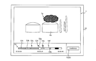
- the seek bar image 53 will be described with reference to FIG. 7A.
- a first bar element 53a (a portion with a diagonal grid) means a portion that has already been reproduced in the inspection image data.
- the second bar element 53b (hatched portion) means, for example, a portion where the occurrence of gas leakage is mechanically detected based on the detection result of the image processing unit 31a. .
- the first mark 53c indicates a portion checked by the user.
- the second mark 53d indicates unnecessary image data.
- the third mark 53e and the fourth mark 53f indicate portions where supplementary information is added by the user.
- the third mark 53e means supplementary information (evidence) closest to the reproduction position mark 53g indicating the reproduction position.
- a white portion means an unreproduced portion.
- a black portion indicates a portion from which data has been deleted.
- the output processing unit 31c generates output information including imaging information and inspection image data under the control of the control unit 35.
- the output processing unit 31c generates output information when an output instruction is input from the operation input unit 33.
- the output processing unit 31c extracts the inspection image data in the range and generates the extracted information as output information.
- the output information may include, for example, inspection image data associated with the supplementary information.
- the output processing unit 31c outputs the output information to an output device such as a printer, for example.
- the output device may be connected to the gas detection device main body 3 by wire or wirelessly.
- the output device may be connected to the gas detection device main body 3 via a network such as the Internet.
- the output processing unit 31c may output the output information to a portable storage medium such as an optical disk, a magneto-optical disk, and a memory card.
- the output processing unit 31c may output the output information to the server.
- the display unit 32 is, for example, a display of a portable terminal included in the gas detection device main body 3.
- a liquid crystal display, an organic EL display, or the like can be used.
- the display is a flat panel display with a touch panel.
- the display unit 32 displays various images under the control of the control unit 35 based on a display signal from the display processing unit 31b.
- the display unit 32 includes an inspection image 7 for the user to detect gas by visual recognition, an auxiliary information input image 5 for the user to input additional information, and a seek bar for the user to check the reproduction status of the inspection image data.
- the image 53 and the like are displayed (see FIGS. 5A to 7A).
- the operation input unit 33 is an input unit and receives, for example, an input of imaging information and an input of supplementary information. In addition, the operation input unit 33 receives an operation related to reproduction of inspection image data and an operation related to imaging of the imaging device 2. Note that the imaging information includes various information necessary for starting imaging by the imaging device 2. The imaging information will be described later.
- the operation input unit 33 receives an output instruction.
- the operation input unit 33 may receive, for example, designation of an item included in the output information together with the output instruction.
- the items of the output information include imaging information described later and other arbitrary information (for example, climate information at the time of imaging).
- the operation input unit 33 may receive designation of a range of inspection image data to be output as output information.
- the user specifies, for example, a range of inspection image data to be output from the seek bar image 53 (see FIG. 7A) displayed on the display unit 32.
- the operation input unit 33 may allow the input of the output instruction only when the imaging information corresponding to the examination region to be imaged is input (when the imaging information is not stored in the storage unit 34). .
- the operation input unit 33 receives the input of the output instruction. It may be prohibited.
- the operation input unit 33 permits the input of the output instruction only when the supplementary information associated with the inspection image data is input (when the supplementary information is not stored in the storage unit 34). You may.
- the operation input unit 33 receives the input of the output instruction. May be prohibited.
- the operation input unit 33 may allow the input of the output instruction only when the imaging information corresponding to the inspection area and the supplementary information corresponding to the inspection image data are input.
- the operation input unit 33 is configured by a flat panel display with a touch panel provided integrally with the display unit 32. Through the operation input unit 33, the user can perform input of imaging information, input of supplementary information, operation of the imaging device 2, and reproduction of inspection image data.
- the operation input unit 33 is not limited to a flat panel display with a touch panel, but may be an input device such as a keyboard, a mouse, or a microphone.
- the control unit 35 includes a CPU 35a (Central Processing Unit) as an arithmetic / control device, a RAM 35b (Random Access Memory), and a ROM 35c (Read Only Memory) as a main storage device.
- the ROM 35c stores basic programs and basic setting data.
- the CPU 35a reads out a program corresponding to the processing content from the ROM 35c or the storage unit 34, develops the program on the RAM 35b, and executes the developed program to centrally control the operation of each block of the gas detection device 1.
- the control unit 35 controls the entire gas detection device 1 by controlling the imaging device 2, the display unit 32, the operation input unit 33, and the storage unit 34 according to their respective functions.
- each functional block is realized by the cooperation of the hardware constituting each functional block and the control unit 35. Note that a part or all of the functions of each functional block may be realized by the control unit 35 executing the program.
- the storage unit 34 is, for example, an auxiliary storage device such as a nonvolatile semiconductor memory (a so-called flash memory) or a hard disk drive.
- the storage unit 34 may be a disk drive that reads and writes information by driving an optical disk such as a CD (Compact Disc) and a DVD (Digital Versatile Disc) and a magneto-optical disk such as an MO (Magneto-Optical disk).
- the storage unit 34 may be a memory card such as a USB memory and an SD card.
- the storage unit 34 stores the imaging information input from the operation input unit 33. Writing of data to the storage unit 34 and reading of data from the storage unit 34 are controlled by the control unit 35.
- the storage unit 34 stores the inspection image data received from the image processing unit 31a.
- the storage unit 34 stores the inspection image data in association with the imaging information.
- the storage unit 34 may store the infrared image data after the image processing received from the image processing unit 31a.
- the storage unit 34 may store the infrared image data after the image processing in association with the imaging information.
- the storage unit 34 may store infrared image data before image processing generated by the infrared imaging unit 22.
- the storage unit 34 may store the infrared image data before the image processing in association with the imaging information.
- the storage unit 34 may store the visible image data generated by the visible light imaging unit 21.
- the storage unit 34 may store the visible image data in association with the imaging information.
- the storage unit 34 stores various information input from the operation input unit 33. Specifically, the storage unit 34 stores the supplementary information input from the operation input unit 33. The storage unit 34 stores the supplementary information in association with the inspection image 7 (see FIG. 5A) displayed on the display unit 32 when the supplementary information is input. When the inspection image 7 is a moving image, the storage unit 34 stores the supplementary information in association with the frame constituting the inspection image 7 displayed on the display unit 32 when the supplementary information is input.
- the storage unit 34 stores image data relating to the supplementary information input image 5. Further, the storage unit 34 stores image data relating to the seek bar image 53.
- the image data relating to the seek bar image 53 includes the above-described image data relating to the first bar element 53a, the second bar element 53b, and the first mark 53c to the fourth mark 53f.
- FIG. 2 is a flowchart illustrating an example of an imaging flow of the gas detection device 1.
- FIG. 3 is a flowchart illustrating an example of a regeneration flow of the gas detection device 1.
- FIG. 4 is a flowchart illustrating an example of an output flow of the gas detection device 1.
- FIGS. 1, 2, 5A, and 5B an operation of the gas detection device 1 when a user inputs supplementary information at an arbitrary timing during imaging by the gas detection device 1 will be described.
- the imaging by the gas detection device 1 is performed in a state where the gas detection device 1 is arranged at a predetermined position where the inspection area including the inspection target can be imaged.
- the gas detection device 1 is disposed at the predetermined position while being supported by a tripod, for example.
- the gas detection device 1 When an instruction to start imaging is input from the operation input unit 33, the gas detection device 1 starts the imaging flow shown in FIG.
- the following processing is realized, for example, by the CPU 35a executing a predetermined program stored in the ROM 35c (see FIG. 1) in response to an input of an instruction to start imaging in the gas detection device 1.
- step S101 in FIG. 2 the display processing unit 31b causes the display unit 32 to display an imaging information input image (not shown) for inputting imaging information under the control of the control unit 35.
- the gas detection device 1 requests the user to input imaging information in step S101 in FIG.
- the imaging information requested by the gas detection device 1 to the user is, for example, information shown in Table 1 below.
- control unit 35 may acquire the imaging information from the imaging history when the inspection area to be imaged is imaged in the past.
- the imaging history is stored in the storage unit 34.
- Such an imaging history is stored in the storage unit 34 in association with the inspection area.
- step S102 of FIG. 2 the control unit 35 determines whether or not imaging information (including imaging information acquired from the imaging history) has been input.
- step S102 If it is determined in step S102 that no imaging information has been input ("NO” in step S102), the control process proceeds to step S101. On the other hand, when it is determined in step S102 that imaging information has been input (“YES” in step S102), the control process proceeds to step S103. Note that as a modification of the flowchart shown in FIG. 2, the determination in step S102 may be omitted. That is, the control process may transit to step S103 regardless of whether or not the imaging information is input in step S101.
- Step S103 of FIG. 2 the imaging device 2 starts imaging the inspection area under the control of the control unit 35.
- the imaging device 2 sequentially outputs visible image data to the processing unit 31 (specifically, the image processing unit 31a) during imaging.
- the imaging device 2 sequentially outputs the infrared image data to the processing unit 31 (specifically, the image processing unit 31a) during imaging.
- the visible image data and the infrared image data generated by the imaging device 2 may be sequentially stored in the storage unit 34.
- the image processing unit 31a receives the infrared image data from the infrared imaging unit 22. Then, the image processing unit 31a performs the above-described gas visualization processing on the received infrared image data to generate infrared image data after image processing.
- the image processing unit 31a receives visible image data from the visible light imaging unit 21 while the imaging device 2 is imaging. Then, the image processing unit 31a generates inspection image data in which the received visible image data is combined with the infrared image data after the image processing.
- the image processing unit 31a sequentially outputs the generated inspection image data to the display processing unit 31b during the imaging by the imaging device 2.
- the display processing unit 31b converts the received inspection image data into a display signal corresponding to the display unit 32 and outputs the display signal, and causes the display unit 32 to display the inspection image 7 (see FIG. 5A). As described above, the inspection image 7 of the inspection area is displayed on the display unit 32 in real time during imaging by the imaging device 2.
- the output processing unit 31c may transmit the inspection image 7 to the server.
- the inspection image 7 received by the server may be displayed on a display unit (such as a display) connected to the server (including connection via a network). According to such a configuration, a person different from the photographer can visually check the inspection image 7 in the inspection area from a remote place in real time. Further, the gas detection device 1 may be configured so that the other person can input supplementary information described later from a remote place.
- the display processing unit 31b always displays the supplementary information input image 5 (specifically, the first input image 51) for inputting supplementary information on the display unit 32 during imaging by the imaging device 2.
- step S104 of FIG. 2 the control unit 35 determines whether there is an instruction to input supplementary information.
- the presence or absence of the input instruction is determined based on, for example, whether or not the user has performed a touch operation on the first input image 51.
- step S104 If it is determined in step S104 that there is no instruction to input supplementary information ("NO” in step S104), the control process proceeds to step S106. On the other hand, if it is determined in step S104 that there is an instruction to input supplementary information ("YES" in step S104), the control process proceeds to step S105.
- step S105 in FIG. 2 the display processing unit 31b causes the display unit 32 to display the second input image 52 under the control of the control unit 35 (see FIG. 5B).
- the user inputs supplementary information from the second input image 52 displayed on the display unit 32 in step S105.
- the user inputs supplementary information on the displayed inspection image 7 from the second input image 52 while the inspection image 7 is displayed on the display unit 32 in step S105.
- the processing of the gas detection device 1 in step S105 is also referred to as supplementary information input processing.
- FIG. 5B is a diagram showing a screen of the display unit 32 on which the second input image 52 is displayed.
- the second input image 52 has an importance input section 52a and a comment input section 52b.
- the user can arbitrarily input information on the importance of the inspection image 7 displayed on the display unit 32 into the importance input unit 52a. Examples of the information regarding the importance include “important”, “normal”, and “unnecessary”.
- the user can input an arbitrary comment on the inspection image 7 displayed on the display unit 32 into the comment input unit 52b.
- a comment on a gas leak such as "gas leak is occurring" can be given.
- the information on the importance and the comment described above are supplementary information.
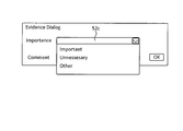
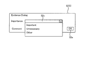
- the importance input section 52a may be a selection-type input section such as the importance input section 52c shown in FIG. 6A.
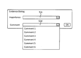
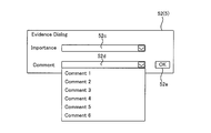
- the comment input section 52b may be a selectable input section such as the comment input section 52d shown in FIG. 6B.
- the display processing unit 31b acquires comment options (also referred to as supplementary information candidates) from the storage unit 34 and causes the comment input unit 52b of the display unit 32 to display the options.
- the option of the comment may be, for example, information on a gas leak state or information on regulation stored in the storage unit 34 in advance.
- the comment option may be, for example, a comment previously input by the user. Further, the comment options may change according to the inspection image 7 displayed on the display unit 32. For example, as a comment option, the relationship between the comment input by the user in the past and the inspection image 7 to which the comment is attached is learned by artificial intelligence (Artificial Intelligence: AI), and based on the learning result. It may be determined.
- AI Artificial Intelligence
- step S105 when the supplementary information is input, the control unit 35 associates the inspection image data (specifically, the frame configuring the inspection image data) displayed on the display unit 32 with the supplementary information. Then, it is stored in the storage unit 34.
- the inspection image data associated with the supplementary information is the inspection image data displayed on the display unit 32 while the second input image 52 is displayed on the display unit 32.
- the inspection image data associated with the supplementary information is displayed at the timing when the second input image 52 is displayed on the display unit 32 (when the first input image 51 of the display unit 32 shown in FIG. 5A is operated). Only the inspection image data (frames constituting the inspection image data) displayed at 32 may be used.
- the range of the inspection image data associated with the supplementary information may be specified by a user's selection operation.
- step S106 of FIG. 2 the control unit 35 determines whether or not there is an instruction to end imaging.
- An instruction to end imaging is input by the user from the operation input unit 33.
- step S106 If it is determined in step S106 that there is no instruction to end imaging (“NO” in step S106), the control process proceeds to step S104. On the other hand, if it is determined in step S106 that an instruction to end imaging has been given (“YES” in step S106), the control process proceeds to step S107.
- step S107 the control unit 35 ends the imaging by the imaging device 2. Then, the control process ends.
- the gas detection device 1 starts the regeneration flow shown in FIG.
- the following processing is realized, for example, by the CPU 35a executing a predetermined program stored in the ROM 35c in response to an instruction to start regeneration in the gas detection device 1.
- step S201 of FIG. 3 the display processing unit 31b acquires inspection image data from the storage unit 34 under the control of the control unit 35.
- the display processing unit 31b converts the acquired inspection image data into a display signal corresponding to the display unit 32 and outputs the display signal, and causes the display unit 32 to display the inspection image 7. In this way, the inspection image data stored in the storage unit 34 is reproduced on the display unit 32.
- the display processing unit 31b constantly displays the supplementary information input image 5 (specifically, the first input image 51) for inputting supplementary information on the display unit 32 during the reproduction of the inspection image data (FIG. 7A).
- the display processing unit 31b always displays the seek bar image 53 (see FIG. 7A) on the display unit 32 during the reproduction of the inspection image data.
- step S202 of FIG. 3 the control unit 35 determines whether or not there is an instruction to input supplementary information.
- the presence or absence of the input instruction is determined based on, for example, whether or not the user has performed a touch operation on the first input image 51.
- step S202 If it is determined in step S202 that there is no instruction to input supplementary information ("NO” in step S202), the control process proceeds to step S204. On the other hand, when it is determined in step S202 that there is an instruction to input supplementary information (“YES” in step S202), the control process proceeds to step S203.
- step S203 of FIG. 3 the display processing unit 31b causes the display unit 32 to display the second input image 52 under the control of the control unit 35 (see FIG. 7B).
- the user inputs supplementary information from the second input image 52 displayed on the display unit 32 in step S203.
- step S203 the user inputs, from the second input image 52, supplementary information on the reproduced and displayed inspection image 7 while the inspection image 7 is being reproduced and displayed on the display unit 32.
- the processing of the gas detection device 1 in step S203 is also referred to as supplementary information input processing.
- the supplementary information input processing is the same as in the above-described imaging flow, and thus the description is omitted.
- step S203 when the supplementary information is input, the control unit 35 associates the inspection image data reproduced on the display unit 32 (specifically, a frame forming the inspection image data) with the supplementary information. Then, it is stored in the storage unit 34.
- the inspection image data associated with the supplementary information is the inspection image data displayed on the display unit 32 while the second input image 52 is displayed on the display unit 32.
- the display processing unit 31b controls the display unit 32 so as to additionally display the third mark 53e indicating the position where the supplementary information is added in the inspection image data on the seek bar image 53. .
- the reproduction position in the seek bar image 53 that is, the reproduction position mark 53g
- the position of the already input supplementary information for example, the third mark 53e
- the display processing unit 31b may cause the display unit 32 to display the content of the supplementary information.
- the reproduction position in the seek bar image 53 (that is, the position of the reproduction position mark 53g in the seek bar image 53) is separated from the third mark 53e by a predetermined distance. Then, the display processing unit 31b controls the display unit 32 so as to end the display of the content of the supplementary information.
- step S204 of FIG. 3 the control unit 35 determines whether or not there is an instruction to end the reproduction.
- An instruction to end imaging is input by the user from the operation input unit 33.
- step S204 If it is determined in step S204 that there is no instruction to end the reproduction ("NO” in step S204), the control process proceeds to step S202. On the other hand, if it is determined in step S204 that there is an instruction to end the reproduction ("YES" in step S204), the control process proceeds to step S205.
- step S205 the control unit 35 ends the reproduction. Then, the control process ends.
- the gas detection device 1 When the output instruction is input from the operation input unit 33, the gas detection device 1 starts the output flow shown in FIG. The following processing is realized, for example, by the CPU 35a executing a predetermined program stored in the ROM 35c in response to an input of an output instruction in the gas detection device 1.
- step S301 of FIG. 4 the control unit 35 determines whether or not there is imaging information.
- step S301 If it is determined in step S301 that there is no imaging information ("NO" in step S301), the control process ends. That is, even when the output instruction is input, the gas detection device 1 prohibits the generation of the output information when the imaging information has not been input.
- step S301 determines whether there is imaging information ("YES" in step S301). If it is determined in step S301 that there is imaging information ("YES" in step S301), the control process proceeds to step S302.
- step S302 in FIG. 4 the output processing unit 31c generates output information including imaging information and inspection image data under the control of the control unit 35.
- the output information may include information other than the imaging information and the image data.
- the user can specify information included in the output information from the operation input unit 33.
- the output processing unit 31c may extract the inspection image data associated with the supplementary information from the inspection image data and generate the output information.
- the output information may include inspection image data associated with supplementary information of the inspection image data.
- the user may specify the range of the inspection image data to be extracted as the output information from the operation input unit 33.
- the output information includes the inspection image data corresponding to the range in the inspection image data.
- the imaging information of the output information generated in step S302 may include, for example, at least the items described in Table 1 above.
- step S303 in FIG. 4 under the control of the control unit 35, the output processing unit 31c outputs the output information to an output terminal (such as a printer) or a storage medium (such as an optical disk, a magneto-optical disk, or a memory card) specified by the user. To a portable storage medium). Note that the output processing unit 31c may automatically attach the output information to a certificate (certification file) relating to the inspection target. Then, the output flow control process ends.
- an output terminal such as a printer
- a storage medium such as an optical disk, a magneto-optical disk, or a memory card
- Supplementary information of any content can be input at any timing.
- Such supplementary information is stored in the storage unit 34 in association with the inspection image 7 displayed on the display unit 32 when the supplementary information is input.
- the user can distinguish between a portion having a high importance in the inspection image 7 and a portion which is not so important.
- the user can distinguish a portion having a high degree of importance from a portion of the inspection image 7 to which the supplementary information is attached and a portion not having the importance.
- the inspection image 7 when the inspection image 7 is stored, a portion having low importance is deleted from the inspection image data, so that the data capacity can be reduced.
- the user checks the inspection image 7 later if the user checks mainly the portion of the inspection image 7 to which supplementary information is added, the efficiency of the checking operation can be improved.
- extracting only inspection image data with supplementary information as output information can reduce the data volume of output information and improve the efficiency of output information confirmation work. it can.
- a gas detection device 1 according to another embodiment of the present invention will be described with reference to the drawings.
- the inspector can visually and easily specify the location of the gas leak in the inspection area by visually checking the inspection image displayed on the display unit.
- the importance of the inspection image for the inspector is completely different between the normal inspection image in which gas leakage does not occur in the inspection target and the emergency inspection image in which gas leakage occurs in the inspection target.
- an inspector may want to continuously view inspection images for a predetermined time including a normal inspection image and an emergency inspection image, but want to partially view only an emergency inspection image.
- the gas leak detection device disclosed in Patent Literature 1 does not have a configuration for responding to such a request.
- FIG. 8 is a block diagram of a gas detection device 1 according to another embodiment of the present invention.
- the gas detection device 1 captures an image of an inspection area including an inspection target (a plant or the like) of a gas production facility, for example. Then, the gas detection device 1 performs image processing for detecting gas on the captured image.
- a gas detection device 1 As shown in FIG. 8, a gas detection device 1 according to another embodiment of the present invention includes an imaging device 2 and a gas detection device main body 3.
- an imaging device 2 and a gas detection device main body 3 in the gas detection device 1 according to the above-described embodiment will be mainly described, and the same components will be denoted by the same reference numerals and description thereof will be omitted. I do.
- the infrared sensor used for the second optical system of the imaging device 2 is, for example, a quantum-type indium antimony (InSb) image sensor, a thermal-type thermopile array sensor, a microbolometer, or the like. Generate image data.
- the infrared imaging unit 22 captures an inspection area including an inspection target of the gas production facility (for example, the plant 6a in FIG. 9A), and converts the infrared image data into the processing unit 31 (specifically, image processing). The data is sequentially output to the section 31a).
- the gas detection device main body 3 includes a processing unit 31, a display unit 32, an operation input unit 33, a storage unit 34, a control unit 35, and the like.
- the processing unit 31 includes at least one dedicated hardware (electronic circuit) corresponding to each processing, such as a DSP (Digital Signal Processor), an ASIC (Application Specific Integrated Circuit), or a PLD (Programmable Logic Device).
- the processing unit 31 includes, as functional blocks, an image processing unit 31a, a display processing unit 31b, an output processing unit 31c, a time information generation unit 31d, and the like. Each function of the processing unit 31 described later is realized under the control of the control unit 35.
- the image processing unit 31a receives the infrared image data of the inspection area from the infrared imaging unit 22.
- the image processing unit 31a performs predetermined image processing for detecting gas on the infrared image data of the inspection area.
- the image processing unit 31a detects, for example, a portion where gas exists in the infrared image data, and visualizes the detected portion to generate gas image data.
- a known method can be used to detect the portion where the gas exists.
- the image processing unit 31a gives a specific color (such as red) to a portion where a gas exists in the infrared image data.
- the image processing section 31a corresponds to the "gas detection section" of the present invention.
- the image processing unit 31a receives the visible image data from the visible light imaging unit 21. Then, the image processing unit 31a generates inspection image data obtained by combining gas image data with visible image data. Further, the image processing unit 31a generates temperature image data from the infrared image data. The image processing unit 31a may generate inspection image data obtained by combining gas image data with infrared image data.
- the image processing unit 31a outputs the inspection image data to the display processing unit 31b and the storage unit 34.
- the storage unit 34 stores the inspection image data in association with the time at which the infrared image data serving as the basis of the inspection image data was captured. More specifically, the storage unit 34 stores the inspection image data in association with detection time information indicating a time at which gas is detected by the image processing unit 31a. The details of the detection time information will be described later.
- the inspection image data is displayed on the display unit 32 as the inspection image 7 (see FIG. 9A).
- the gas image 7a (see FIG. 9A) corresponding to the gas in the inspection image 7 is given the specific color.
- ⁇ Display processing unit> the function of the display processing unit 31b will be described.
- the function of the display processing unit 31b is realized under the control of the control unit 35.
- Such a display processing unit 31b controls display on a display unit 32 described later.
- the display processing unit 31b causes the display unit 32 to display an imaging information input image (not shown) for inputting imaging information.
- the imaging information includes various information necessary for starting imaging by the imaging device 2.
- the imaging information includes a customer ID (Identification), a user ID, an inspector name, an inspection company name, an inspection date and time, an inspection type, a site name, a facility name, a facility ID, and a GPS (Global Positioning System). Includes the latitude and longitude of the located facility.
- the image data serving as the basis of the imaging information input image is stored in the storage unit 34 in advance.
- the display processing unit 31b converts the inspection image data received from the image processing unit 31a into a display signal corresponding to the display unit 32 and outputs the display signal, and causes the display unit 32 to display the inspection image 7 (see FIG. 9A).
- the display processing unit 31b causes the display unit 32 to display the supplementary information input image 5 (see FIG. 9A) for inputting supplementary information for the examination image 7 together with the examination image 7.
- the supplementary information includes information regarding the importance of the inspection image 7 displayed on the display unit 32 and a comment. Examples of the information on the degree of importance include “important”, “normal”, and “unnecessary”.
- the comment for example, a comment on a gas leak such as "gas leak is occurring" can be given.
- FIG. 9A is a diagram illustrating an example of the inspection image 7 and the supplementary information input image 5 displayed on the display unit 32.
- the supplementary information input image 5 is, for example, an icon.
- the image data serving as the basis of the supplementary information input image 5 is stored in the storage unit 34 in advance.
- the supplementary information input image 5 may be composed of, for example, a plurality of images that are sequentially displayed in a pop-up manner for each input item by a user's touch operation.
- the supplementary information input image 5 includes a first input image 51 (see FIG. 9A) that is always displayed on the display unit 32 together with the inspection image 7, and a user operates the first input image 51 (for example, , A touch operation), and a second input image 52 (FIG. 9B) displayed on the display unit 32.
- the display processing unit 31b causes the display unit 32 to display the second input image 52 when the user operates the first input image 51.
- the second input image 52 has an importance input section 52a and a comment input section 52b.
- the user can arbitrarily input information on the importance of the inspection image 7 displayed on the display unit 32 into the importance input unit 52a. Further, the user can input a comment on the inspection image 7 displayed on the display unit 32 into the comment input unit 52b.
- the importance input section 52a may be an input section in which input items are selectively displayed by pull-down, like the importance input section 52c shown in FIG. 10A.
- the comment input section 52b may be an input section in which input items are selectively displayed by pull-down, like the comment input section 52d shown in FIG. 10B.
- the time at which the first input image 51 is operated is stored in the storage unit 34 in association with the time information of the captured image captured by the imaging device 2 and the time information of the inspection image 7 as the time at which the input is received.
- the supplementary information can be stored not only at the time of recording but also at the time of reproduction.
- the display processing unit 31b deletes the second input image 52 from the display unit 32. Note that the display processing unit 31b may automatically delete the second input image 52 after a predetermined period of time has elapsed since the second input image 52 was pop-up displayed.
- the display processing unit 31b converts the inspection image data stored in the storage unit 34 into the display unit 32 when a reproduction start instruction (hereinafter, referred to as a “reproduction start instruction”) is input through the operation input unit 33. Is converted into a display signal corresponding to and output, and the inspection image 7 is displayed on the display unit 32. At this time, the display processing unit 31b causes the display unit 32 to display the supplementary information input image 5 together with the inspection image 7.
- a reproduction start instruction hereinafter, referred to as a “reproduction start instruction”
- the output processing unit 31c generates output information including inspection image data under the control of the control unit 35.
- the output processing unit 31c generates output information when an output instruction is input from the operation input unit 33.
- the output processing unit 31c outputs the output information to an output device such as a printer, for example.
- the output device may be connected to the gas detection device main body 3 by wire or wirelessly.
- the output device may be connected to the gas detection device main body 3 via a network such as the Internet.
- the output processing unit 31c may output the output information to a portable storage medium such as an optical disk, a magneto-optical disk, and a memory card.
- the output processing unit 31c may output the output information to the server.
- the control unit 35 includes a CPU 35a (Central Processing Unit) as an arithmetic / control device, a RAM 35b (Random Access Memory), and a ROM 35c (Read Only Memory) as a main storage device.
- the ROM 35c stores basic programs and basic setting data.
- the CPU 35a reads out a program corresponding to the processing content from the ROM 35c or the storage unit 34, develops the program on the RAM 35b, and executes the developed program to centrally control the operation of each block of the gas detection device 1.
- the control unit 35 controls the entire gas detection device 1 by controlling the imaging device 2, the display unit 32, the operation input unit 33, and the storage unit 34 according to their respective functions.
- each functional block is realized by the cooperation of the hardware constituting each functional block and the control unit 35. Note that a part or all of the functions of each functional block may be realized by the control unit 35 executing the program.
- the control unit 35 determines the reliability of gas detection based on signals from the peripheral sensors 8 of the temperature sensor 81, the wind speed sensor 82, and the vibration sensor 83.
- the temperature sensor 81 measures the ambient temperature around the gas detection device 1.
- the wind speed sensor 82 measures the wind speed around the gas detection device 1 or around the inspection object. For the wind speed, wind speed information of the shooting location may be obtained using a network.
- the vibration sensor 83 measures a vibration state of the imaging device 2. When the temperature difference between the temperature indicated by the image of the inspection area imaged by the infrared imaging unit 22 and the temperature indicated by the temperature sensor 81 is equal to or lower than a predetermined temperature, the control unit 35 sets the wind speed indicated by the wind speed sensor 82 to a predetermined value or higher.
- control unit 35 stores the time information of the inspection image 7 and the invalid information in the storage unit 34 in association with each other.
- the storage unit 34 is, for example, an auxiliary storage device such as a nonvolatile semiconductor memory (a so-called flash memory) or a hard disk drive.
- the storage unit 34 may be a disk drive that reads and writes information by driving an optical disk such as a CD (Compact Disc) and a DVD (Digital Versatile Disc) and a magneto-optical disk such as an MO (Magneto-Optical disk).
- the storage unit 34 may be a memory card such as a USB memory and an SD card.
- the storage unit 34 stores the imaging information input from the operation input unit 33. Writing of data to the storage unit 34 and reading of data from the storage unit 34 are controlled by the control unit 35.
- the storage unit 34 stores the inspection image data received from the image processing unit 31a.
- the storage unit 34 stores the inspection image data in association with the imaging information.
- the storage unit 34 stores the inspection image data in association with detection time information indicating a time at which gas is detected by the image processing unit 31a.
- the storage unit 34 may store the infrared image data after the image processing received from the image processing unit 31a.
- the storage unit 34 may store the infrared image data after the image processing in association with the imaging information.
- the storage unit 34 may store the detection time information in association with the infrared image data after the image processing.
- the storage unit 34 may store infrared image data before image processing generated by the infrared imaging unit 22.
- the storage unit 34 may store the infrared image data before the image processing in association with the imaging information.
- the storage unit 34 may store the detection time information in association with the infrared image data before image processing.
- the storage unit 34 may store the visible image data generated by the visible light imaging unit 21.
- the storage unit 34 may store the visible image data in association with the imaging information.
- the storage unit 34 may store the detection time information in association with the visible image data.
- the storage unit 34 may store temperature image data.
- the storage unit 34 may store the detection time information in association with the temperature image data.
- the storage unit 34 stores various information input from the operation input unit 33. Specifically, the storage unit 34 stores the supplementary information input from the operation input unit 33. The storage unit 34 stores the supplementary information in association with the inspection image 7 (see FIG. 11A) displayed on the display unit 32 when the supplementary information is input. When the inspection image 7 is a moving image, the storage unit 34 stores the supplementary information in association with the frame constituting the inspection image 7 displayed on the display unit 32 when the supplementary information is input. The supplementary information may be stored in association with each of the infrared image data after the image processing, the infrared image data before the image processing, the visible image data, and the temperature image data.
- information on the reliability of gas detection is stored in association with the inspection image.
- the information relating to the reliability of gas detection may be stored in association with each of the infrared image data after the image processing, the infrared image data before the image processing, the visible image data, and the temperature image data.
- the storage unit 34 stores image data relating to the supplementary information input image 5.
- the display unit 32 is, for example, a display of a portable terminal included in the gas detection device main body 3.
- a liquid crystal display, an organic EL display, or the like can be used.
- the display is a flat panel display with a touch panel.
- the display unit 32 displays a plurality of types of images based on display signals from the display processing unit 31b (see FIG. 8) under the control of the control unit 35. Specifically, the display unit 32 displays an inspection image 7 or the like for the user to visually detect the gas (see FIG. 9A).
- the operation input unit 33 is an input unit and receives, for example, input of imaging information. In addition, the operation input unit 33 receives an operation related to reproduction of inspection image data and an operation related to imaging of the imaging device 2.
- the operation input unit 33 receives an instruction to output information related to imaging.
- the operation input unit 33 may receive, for example, designation of an item included in the output information together with the output instruction.
- the items of the output information include imaging information and other arbitrary information (for example, climate information at the time of imaging).
- the operation input unit 33 is configured by a flat panel display with a touch panel provided integrally with the display unit 32. The user can perform input of imaging information, operation of the imaging device 2, and reproduction operation of inspection image data via the operation input unit 33.
- the operation input unit 33 is not limited to a flat panel display with a touch panel, but may be an input device such as a keyboard, a mouse, or a microphone.
- the gas detection device 1 when gas is detected in the inspection area, a report on gas detection is created and submitted to the client (client). In preparing a report or the like, inspection image data is reproduced to check the inspection image.
- the display processing unit 31b converts the inspection image data read from the storage unit 34 into a display signal corresponding to the display unit 32 and outputs the signal. Display the inspection image 7 (see FIG. 9A).
- the user By visually recognizing the inspection image 7, the user (inspector) specifies information such as the location of the gas leak in the inspection area, the time when the gas leak occurred, and the situation after the gas leak occurred.
- the importance of the inspection image for the user is completely different between a normal inspection image in which gas leakage does not occur in the inspection region and an emergency inspection image in which gas leakage occurs in the inspection region.
- a user may want to continuously view inspection images for a predetermined period of time including a normal inspection image and an emergency inspection image, while partially viewing only an emergency inspection image. is there.
- the display processing unit 31b converts the inspection image data stored in the storage unit 34 into a display signal corresponding to the display unit 32 and outputs the display signal. Then, the inspection image 7 is displayed on the display unit 32. At this time, the display processing unit 31b causes the display unit 32 to display a seek bar image 53 (see FIG. 11A) for visualizing the display position on the time axis together with the inspection image 7.
- the image data serving as the base of the seek bar image 53 is stored in the storage unit 34 in advance.
- the first bar element 53a indicates the time during which no gas was detected.
- the second bar element 53b indicates a time when gas is detected by the image processing unit 31a.
- the third bar element 53p indicates a portion where inspection image data is not present or has been deleted.
- the fourth bar element 53q indicates an invalid part of the inspection image data.
- the fifth bar element 53r indicates a portion where the inspection image 7 has already been reproduced.
- the sixth bar element 53s means an unplayed portion of the inspection image 7.
- the second bar element 53b corresponds to “detection time information” of the present invention.
- the function of the time information generation unit 31d is realized under the control of the control unit 35.
- the time information generating unit 31d generates image data serving as the first bar element 53a and the second bar element 53b based on the time at which the infrared image data serving as the base of the inspection image data was captured.
- the time information generation unit 31d generates image data serving as the basis of the fourth bar element 53q based on the information on reliability stored in the storage unit.
- the time information generation unit 31d generates the fifth bar element 53r and the sixth bar element 53s according to the reproduced part of the inspection image 7.
- the display processing unit 31b displays the first bar element 53a, the second bar element 53b, the third bar element 53p, the fourth bar element 53q, the fifth bar element 53r, and the sixth bar element 53s on the display unit 32 by using a seek bar image. 53 and displayed.
- each of the first mark 53c to the fourth mark 53f shown in FIGS. 11A and 11B is referred to as an evidence mark.
- the evidence mark is displayed on the seek bar image 53.
- the position where the evidence mark is displayed indicates the time when the input of the supplementary information was received (reception time information).
- the evidence mark is a part indicating what supplementary information is added by the user.
- the display processing unit 31b is a third mark 53e that is located after the reproduction position mark 53g (see FIG. 11A, also referred to as a slider) indicating the position where the inspection image is reproduced, and is the mark closest to the reproduction position mark 53g. (For example, display with bold font, highlight display).
- the time information generation unit 31d When the third mark 53e is highlighted and displayed, the time information generation unit 31d generates selection range information 53h indicating a time zone selected corresponding to the third mark 53e.
- the time information generation unit 31d sets a certain time (time zone) between a predetermined time before the position of the third mark 53e and a predetermined time after the position of the third mark 53e as the selection range information. Generated as 53h.
- the fifth mark 53i indicates the front end of the selection range information 53h.
- the sixth mark 53j indicates the rear end of the selection range information 53h. The user can arbitrarily change the selection range information 53h by moving the position of the fifth mark 53i or the sixth mark 53j via the operation input unit 33.
- the first mark 53c reflected and displayed on the seek bar image 53 means a portion to which supplementary information with high importance is added.
- the second mark 53d indicates a portion to which supplemental information with low importance is added.
- the third mark 53e and the fourth mark 53f mean portions to which other supplementary information is added.
- the selection range information 53h includes a third mark 53e.
- the third mark 53e is selected, and selection range information 53h corresponding to the third mark 53e is displayed.
- selection range information (not shown) corresponding to the fourth mark 53f is displayed.
- the output processing unit 31c uses the supplementary information related to the third mark 53e (or the fourth mark 53f) as the output information. Generate and output to another device.
- the gas detection device 1 is connected to a personal computer (PC) via a network
- the other devices include a local folder of the PC, a flash memory such as an SD card, and a gas detection device.
- the server 1 includes an output device such as a printer, and a portable storage medium such as an optical disk.
- the output processing unit 31c When outputting the supplementary information, the output processing unit 31c reads out the inspection image data associated with the third mark 53e (or the fourth mark 53f) from the storage unit 34 and outputs it to another device.
- FIG. 12 is a flowchart illustrating an example of the operation of the gas detection device 1.
- step S400 shown in FIG. 12 the image processing unit 31a acquires infrared image data from the infrared imaging unit 22 and visible light image data from the visible light imaging unit 21.
- step S410 the image processing section 31a generates inspection image data based on the infrared image data and the visible light image data.
- step S420 the control unit 35 causes the storage unit 34 to store the inspection image data.
- step S430 the control unit 35 determines whether or not an instruction to reproduce the inspection image 7 has been input via the operation input unit 33. If a reproduction instruction has been input ("YES” in step S430), the process proceeds to step S440. If a reproduction instruction has not been input (“NO” in step S430), the process returns to a step before step S430.
- step S440 the processing unit 31 generates a playback screen. Specifically, the time information generation unit 31d generates image data of the first bar element 53a, the second bar element 53b, the third bar element 53p, and the fourth bar element 53q.
- step S450 the display processing unit 31b causes the display unit 32 to display a playback screen.
- the seek bar image 53 is displayed in the first area of the playback screen.
- a seek bar image 53 is displayed in the second area of the playback screen.
- the supplementary information input image 5 is displayed in the third area of the reproduced image.
- image processing is performed on the infrared image data of the inspection region imaged by the infrared imaging unit 22 to visualize the gas in the inspection region.
- the inspection image 7 can be visually recognized efficiently based on the second bar element 53b.
- the user can easily select the inspection image 7 corresponding to the second bar element 53b from the inspection images 7, attach the selected inspection image 7 to the report, and send the requester (client). Can be submitted to
- the display processing unit 31b emphasizes and displays the evidence mark according to the position of the reproduction position mark 53g (slider). For example, when the position of the slider is within the predetermined time of the evidence mark, the display processing unit 31b highlights and displays the next evidence mark within the same predetermined time. Thereby, the inspection image 7 can be visually recognized efficiently based on the importance of the highlighted evidence mark.
- the display processing unit 31b designates the reproduction position mark 53g (slider).
- the mark may be returned to a position corresponding to the first frame of the offset value (for example, the number of data for a predetermined number of seconds) and displayed.
- the display processing unit 31b may move the slider to the tap position and display the slider.
- the reproduction of the inspection image 7 is continued from the tap position.
- the display processing unit 31b may hold and display the slider at that position.
- the display processing unit 31b may display the slider in a released state. Thereby, the reproduction of the inspection image 7 is restarted.
- evidence of high importance may be placed in a higher layer.
- less important or unnecessary evidence may be placed in lower layers.
- more updated evidence may be placed on higher layers. If the evidence mark is highlighted, the evidence may be moved to that layer to make it easier to select. Since the position of the layer changes according to the importance of the evidence, the handling of the evidence can be performed easily.
- the time information generating unit 31d generates the selection range information 53h such that the selection range information 53h does not include the fourth bar element 53q indicating an invalid portion of the inspection image data.
- the display processing unit 31b may display the second bar element 53b indicating the time at which gas is detected by changing the color density according to the gas leakage amount. This makes it easier for the user to understand the degree of danger.
- the display processing unit 31b may further display the second bar element 53b in a more emphasized manner. In this case, for example, the display processing unit 31b may display the screen of the inspection image 7 so as to surround the screen with a red frame.
- the display processing unit 31b may cause the seek bar image 53 to reflect the mark indicating the break position of the data at predetermined time intervals.
- the display processing unit 31b displays the seek bar image 53 when the inspection image 7 is reproduced.
- the present invention is not limited to this, and the display may be performed during imaging.
- the display processing unit 31b displays the seek bar image 53 on the inspection image 7, but the infrared image after image processing, the infrared image before image processing, the visible image, or the temperature image May be displayed.
Landscapes
- Engineering & Computer Science (AREA)
- Theoretical Computer Science (AREA)
- Physics & Mathematics (AREA)
- General Physics & Mathematics (AREA)
- General Engineering & Computer Science (AREA)
- Human Computer Interaction (AREA)
- Multimedia (AREA)
- Signal Processing (AREA)
- Quality & Reliability (AREA)
- Computer Vision & Pattern Recognition (AREA)
- Investigating Or Analysing Materials By Optical Means (AREA)
- Examining Or Testing Airtightness (AREA)
Abstract
L'invention concerne un dispositif de détection de gaz permettant d'attribuer des informations arbitraires à une image spécifique dans une image d'inspection. Le dispositif de détection de gaz comprend : une unité de traitement d'image permettant de visualiser un gaz par la réalisation d'un traitement d'image sur des données d'image infrarouge dans une région de détection capturée par une unité de capture d'image ; une unité de traitement d'affichage permettant d'afficher, sur une unité d'affichage, une image d'inspection à laquelle les résultats du traitement d'image ont été appliqués ; une unité d'entrée permettant de recevoir une entrée d'informations supplémentaires concernant l'image d'inspection affichée sur l'unité d'affichage ; et une unité de mémoire permettant de mémoriser l'image d'inspection et les informations supplémentaires en association les unes avec les autres.
Priority Applications (2)
| Application Number | Priority Date | Filing Date | Title |
|---|---|---|---|
| JP2020532159A JP7359149B2 (ja) | 2018-07-25 | 2019-04-12 | ガス検出装置、ガス検出方法、およびプログラム |
| US17/263,030 US11568529B2 (en) | 2018-07-25 | 2019-04-12 | Gas detection device that visualizes gas |
Applications Claiming Priority (4)
| Application Number | Priority Date | Filing Date | Title |
|---|---|---|---|
| JP2018139158 | 2018-07-25 | ||
| JP2018-139158 | 2018-07-25 | ||
| JP2018-153951 | 2018-08-20 | ||
| JP2018153951 | 2018-08-20 |
Publications (1)
| Publication Number | Publication Date |
|---|---|
| WO2020021785A1 true WO2020021785A1 (fr) | 2020-01-30 |
Family
ID=69182188
Family Applications (1)
| Application Number | Title | Priority Date | Filing Date |
|---|---|---|---|
| PCT/JP2019/015889 Ceased WO2020021785A1 (fr) | 2018-07-25 | 2019-04-12 | Dispositif de détection de gaz, procédé de détection de gaz, procédé de commande d'affichage et programme |
Country Status (3)
| Country | Link |
|---|---|
| US (1) | US11568529B2 (fr) |
| JP (1) | JP7359149B2 (fr) |
| WO (1) | WO2020021785A1 (fr) |
Cited By (3)
| Publication number | Priority date | Publication date | Assignee | Title |
|---|---|---|---|---|
| WO2021181675A1 (fr) * | 2020-03-13 | 2021-09-16 | コニカミノルタ株式会社 | Système et procédé de gestion d'inspection du gaz, et programme |
| JPWO2021205574A1 (fr) * | 2020-04-08 | 2021-10-14 | ||
| WO2022070943A1 (fr) * | 2020-09-29 | 2022-04-07 | コニカミノルタ株式会社 | Appareil et procédé de traitement d'image pour la visualisation de gaz, et programme |
Families Citing this family (2)
| Publication number | Priority date | Publication date | Assignee | Title |
|---|---|---|---|---|
| WO2020021785A1 (fr) * | 2018-07-25 | 2020-01-30 | コニカミノルタ株式会社 | Dispositif de détection de gaz, procédé de détection de gaz, procédé de commande d'affichage et programme |
| DE102019132173A1 (de) * | 2019-11-27 | 2021-05-27 | Endress+Hauser Conducta Gmbh+Co. Kg | Verfahren zur Konfiguration zur Übertragung von Daten von einem Feldgerät |
Citations (7)
| Publication number | Priority date | Publication date | Assignee | Title |
|---|---|---|---|---|
| JP2005533997A (ja) * | 2002-05-21 | 2005-11-10 | フリル システムズ アクチボラゲット | Irカメラ検査の方法および装置 |
| JP2009192469A (ja) * | 2008-02-18 | 2009-08-27 | Tokyo Electric Power Co Inc:The | フランジ用アタッチメント、ガス漏れ検知システムおよびコンピュータプログラム |
| JP2010271094A (ja) * | 2009-05-20 | 2010-12-02 | Hitachi High-Technologies Corp | ガスリーク検査装置 |
| JP2013207492A (ja) * | 2012-03-28 | 2013-10-07 | Azbil Corp | 携帯端末装置 |
| US20160097713A1 (en) * | 2014-07-07 | 2016-04-07 | Rebellion Photonics, Inc. | Gas leak emission quantification with a gas cloud imager |
| JP2016161397A (ja) * | 2015-03-02 | 2016-09-05 | コニカミノルタ株式会社 | 流体漏れ検知装置 |
| WO2017022286A1 (fr) * | 2015-08-03 | 2017-02-09 | ソニー株式会社 | Système de traitement d'informations, procédé de traitement d'informations et support d'enregistrement |
Family Cites Families (29)
| Publication number | Priority date | Publication date | Assignee | Title |
|---|---|---|---|---|
| US8269171B2 (en) * | 2008-09-26 | 2012-09-18 | Bae Systems Information And Electronic Systems Integration Inc. | System and method for detecting, tracking and identifying a gas plume |
| WO2011079208A1 (fr) * | 2009-12-24 | 2011-06-30 | Flir Systems, Inc. | Caméras avec capacités d'élaboration de rapports intégrées |
| JP5343054B2 (ja) | 2010-09-09 | 2013-11-13 | 三菱電機ビルテクノサービス株式会社 | ガス漏れ検出装置 |
| JP5585889B2 (ja) * | 2011-08-23 | 2014-09-10 | コニカミノルタ株式会社 | 表示データ生成装置及び表示制御システム並びに表示制御プログラム |
| JP5533837B2 (ja) * | 2011-11-02 | 2014-06-25 | コニカミノルタ株式会社 | 手書き入力装置及び手書き入力制御プログラム |
| JP5900388B2 (ja) * | 2013-03-15 | 2016-04-06 | コニカミノルタ株式会社 | オブジェクト表示装置及び操作制御方法並びに操作制御プログラム |
| JP5818172B2 (ja) * | 2013-06-21 | 2015-11-18 | コニカミノルタ株式会社 | 情報表示装置及び表示制御プログラム並びに表示制御方法 |
| JP6558438B2 (ja) * | 2015-07-17 | 2019-08-14 | コニカミノルタ株式会社 | ガス検知装置およびガス検知方法 |
| WO2017014097A1 (fr) * | 2015-07-17 | 2017-01-26 | コニカミノルタ株式会社 | Dispositif de détection de gaz et procédé de détection de gaz |
| US20180222581A1 (en) * | 2015-08-04 | 2018-08-09 | Konica Minolta, Inc. | Gas Detection Device and Gas Detection Method |
| US11287407B2 (en) * | 2015-10-19 | 2022-03-29 | University Of North Texas | Dynamic reverse gas stack model for portable chemical detection devices to locate threat and point-of-source from effluent streams |
| JP6665863B2 (ja) * | 2015-10-29 | 2020-03-13 | コニカミノルタ株式会社 | 漏洩ガス検出装置および漏洩ガス検出方法 |
| WO2017150565A1 (fr) * | 2016-03-03 | 2017-09-08 | コニカミノルタ株式会社 | Dispositif d'estimation de position de fuite de gaz, procédé d'estimation de position de fuite de gaz, et programme d'estimation de position de fuite de gaz |
| EP3436193A1 (fr) * | 2016-03-28 | 2019-02-06 | Nanoimmunotech, S.L. | Éléments microfluidiques pour la détection d'analytes sur la base des propriétés de conversion de lumière en chaleur de nanoparticules métalliques |
| CN109196356B (zh) * | 2016-03-31 | 2021-08-10 | 霍尼韦尔国际公司 | 克莱兹代尔气体检测器 |
| US10916258B2 (en) * | 2017-06-30 | 2021-02-09 | Telegraph Peak Technologies, LLC | Audio channel monitoring by voice to keyword matching with notification |
| JP7238778B2 (ja) * | 2017-09-27 | 2023-03-14 | コニカミノルタ株式会社 | ガス撮像装置及び画像取得方法 |
| WO2019099096A1 (fr) * | 2017-11-16 | 2019-05-23 | MultiSensor Scientific, Inc. | Systèmes et procédés d'imagerie multispectrale et de détection de gaz à l'aide d'une source d'éclairage à balayage et d'un capteur optique |
| US10914653B2 (en) * | 2018-05-03 | 2021-02-09 | Quantum IR Technologies, LLC | Infrared imaging systems and methods for oil leak detection |
| US10810858B2 (en) * | 2018-05-03 | 2020-10-20 | Quantum IR Technologies, LLC | Infrared imaging systems and methods for gas leak detection |
| WO2019220761A1 (fr) * | 2018-05-16 | 2019-11-21 | コニカミノルタ株式会社 | Dispositif de type caméra, système de contrôle de fuite de gaz, procédé de contrôle de fuite de gaz et programme de contrôle de fuite de gaz |
| WO2020021785A1 (fr) * | 2018-07-25 | 2020-01-30 | コニカミノルタ株式会社 | Dispositif de détection de gaz, procédé de détection de gaz, procédé de commande d'affichage et programme |
| WO2020039606A1 (fr) * | 2018-08-20 | 2020-02-27 | コニカミノルタ株式会社 | Dispositif de détection de gaz, dispositif de traitement d'informations et programme |
| WO2020039605A1 (fr) * | 2018-08-20 | 2020-02-27 | コニカミノルタ株式会社 | Dispositif de détection de gaz, dispositif de traitement d'informations et programme |
| WO2020090125A1 (fr) * | 2018-10-29 | 2020-05-07 | コニカミノルタ株式会社 | Procédé de prise en charge d'inspection, dispositif de prise en charge d'inspection et programme de prise en charge d'inspection |
| EP3975102A4 (fr) * | 2019-05-20 | 2022-08-03 | Konica Minolta, Inc. | Système de gestion de données d'inspection, dispositif de gestion, procédé de gestion, et dispositif terminal |
| US11438554B2 (en) * | 2019-08-09 | 2022-09-06 | Mission Support and Test Services, LLC | System and method for remote detection and location of gas leaks |
| JP2021140524A (ja) * | 2020-03-06 | 2021-09-16 | 株式会社東芝 | 検査端末装置、検査装置、検査システム、及び、検査プログラム |
| US11392897B1 (en) * | 2020-08-10 | 2022-07-19 | United Services Automobile Association (Usaa) | Intelligent system and method for assessing structural damage using aerial imagery |
-
2019
- 2019-04-12 WO PCT/JP2019/015889 patent/WO2020021785A1/fr not_active Ceased
- 2019-04-12 US US17/263,030 patent/US11568529B2/en active Active
- 2019-04-12 JP JP2020532159A patent/JP7359149B2/ja active Active
Patent Citations (7)
| Publication number | Priority date | Publication date | Assignee | Title |
|---|---|---|---|---|
| JP2005533997A (ja) * | 2002-05-21 | 2005-11-10 | フリル システムズ アクチボラゲット | Irカメラ検査の方法および装置 |
| JP2009192469A (ja) * | 2008-02-18 | 2009-08-27 | Tokyo Electric Power Co Inc:The | フランジ用アタッチメント、ガス漏れ検知システムおよびコンピュータプログラム |
| JP2010271094A (ja) * | 2009-05-20 | 2010-12-02 | Hitachi High-Technologies Corp | ガスリーク検査装置 |
| JP2013207492A (ja) * | 2012-03-28 | 2013-10-07 | Azbil Corp | 携帯端末装置 |
| US20160097713A1 (en) * | 2014-07-07 | 2016-04-07 | Rebellion Photonics, Inc. | Gas leak emission quantification with a gas cloud imager |
| JP2016161397A (ja) * | 2015-03-02 | 2016-09-05 | コニカミノルタ株式会社 | 流体漏れ検知装置 |
| WO2017022286A1 (fr) * | 2015-08-03 | 2017-02-09 | ソニー株式会社 | Système de traitement d'informations, procédé de traitement d'informations et support d'enregistrement |
Cited By (5)
| Publication number | Priority date | Publication date | Assignee | Title |
|---|---|---|---|---|
| WO2021181675A1 (fr) * | 2020-03-13 | 2021-09-16 | コニカミノルタ株式会社 | Système et procédé de gestion d'inspection du gaz, et programme |
| US12146812B2 (en) | 2020-03-13 | 2024-11-19 | Konica Minolta, Inc. | Gas inspection management system, gas inspection management method, and instructions for gas inspection management |
| JPWO2021205574A1 (fr) * | 2020-04-08 | 2021-10-14 | ||
| WO2021205574A1 (fr) * | 2020-04-08 | 2021-10-14 | コニカミノルタ株式会社 | Système de gestion d'installation |
| WO2022070943A1 (fr) * | 2020-09-29 | 2022-04-07 | コニカミノルタ株式会社 | Appareil et procédé de traitement d'image pour la visualisation de gaz, et programme |
Also Published As
| Publication number | Publication date |
|---|---|
| US20210312602A1 (en) | 2021-10-07 |
| US11568529B2 (en) | 2023-01-31 |
| JP7359149B2 (ja) | 2023-10-11 |
| JPWO2020021785A1 (ja) | 2021-08-02 |
Similar Documents
| Publication | Publication Date | Title |
|---|---|---|
| JP7359149B2 (ja) | ガス検出装置、ガス検出方法、およびプログラム | |
| US10796543B2 (en) | Display control apparatus, display control method, camera system, control method for camera system, and storage medium | |
| US10404947B2 (en) | Information processing apparatus, information processing method, camera system, control method for camera system, and storage medium | |
| EP2779632B1 (fr) | Dispositif électronique et son procédé de fonctionnement | |
| KR20170000773A (ko) | 영상 처리 장치 및 방법 | |
| JP7294343B2 (ja) | ガス検出装置、情報処理装置およびプログラム | |
| KR20210056338A (ko) | 이미지들에 대한 다중 영역 검출 | |
| US20240267611A1 (en) | Systems and methods for imaging with a first camera to simulate a second camera | |
| US8866953B2 (en) | Mobile device and method for controlling the same | |
| US11049527B2 (en) | Selecting a recording mode based on available storage space | |
| US20160353021A1 (en) | Control apparatus, display control method and non-transitory computer readable medium | |
| JP6602067B2 (ja) | 表示制御装置、表示制御方法、プログラム | |
| WO2020012864A1 (fr) | Dispositif de détection de gaz, procédé de détection de gaz et programme | |
| US20180063344A1 (en) | Mobile device and method for controlling the same | |
| JP6661312B2 (ja) | 監視システム、情報処理方法及びプログラム | |
| US20170078515A1 (en) | Information recording device, information recording method, and non-transitory storage medium storing information recording medium | |
| JP2011119832A (ja) | 画像表示装置および画像表示方法 | |
| US9736380B2 (en) | Display control apparatus, control method, and storage medium | |
| US12464228B2 (en) | Information processing apparatus, control apparatus, and control method | |
| JP2021118492A (ja) | 画像処理装置および画像処理方法 | |
| WO2020075624A1 (fr) | Dispositif de traitement d'informations, programme, procédé de traitement d'informations, dispositif de fourniture d'informations, procédé de fourniture d'informations, dispositif de commande de présentation, procédé de commande de présentation, et système de traitement d'informations | |
| JP5517895B2 (ja) | 端末装置 | |
| JP5264274B2 (ja) | 通信装置、カメラシステム、制御方法およびプログラム | |
| JP7546881B2 (ja) | 動画撮影支援システム、動画撮影支援システムの制御方法及びプログラム | |
| JP4478047B2 (ja) | 情報提示装置及び情報提示方法とそのプログラム |
Legal Events
| Date | Code | Title | Description |
|---|---|---|---|
| 121 | Ep: the epo has been informed by wipo that ep was designated in this application |
Ref document number: 19841575 Country of ref document: EP Kind code of ref document: A1 |
|
| ENP | Entry into the national phase |
Ref document number: 2020532159 Country of ref document: JP Kind code of ref document: A |
|
| NENP | Non-entry into the national phase |
Ref country code: DE |
|
| 122 | Ep: pct application non-entry in european phase |
Ref document number: 19841575 Country of ref document: EP Kind code of ref document: A1 |